JP5542679B2 - Hose clamp - Google Patents
Hose clamp Download PDFInfo
- Publication number
- JP5542679B2 JP5542679B2 JP2010532676A JP2010532676A JP5542679B2 JP 5542679 B2 JP5542679 B2 JP 5542679B2 JP 2010532676 A JP2010532676 A JP 2010532676A JP 2010532676 A JP2010532676 A JP 2010532676A JP 5542679 B2 JP5542679 B2 JP 5542679B2
- Authority
- JP
- Japan
- Prior art keywords
- strap
- spring element
- hose clamp
- hose
- spring
- Prior art date
- Legal status (The legal status is an assumption and is not a legal conclusion. Google has not performed a legal analysis and makes no representation as to the accuracy of the status listed.)
- Expired - Fee Related
Links
Images


Classifications
-
- F—MECHANICAL ENGINEERING; LIGHTING; HEATING; WEAPONS; BLASTING
- F16—ENGINEERING ELEMENTS AND UNITS; GENERAL MEASURES FOR PRODUCING AND MAINTAINING EFFECTIVE FUNCTIONING OF MACHINES OR INSTALLATIONS; THERMAL INSULATION IN GENERAL
- F16L—PIPES; JOINTS OR FITTINGS FOR PIPES; SUPPORTS FOR PIPES, CABLES OR PROTECTIVE TUBING; MEANS FOR THERMAL INSULATION IN GENERAL
- F16L33/00—Arrangements for connecting hoses to rigid members; Rigid hose connectors, i.e. single members engaging both hoses
- F16L33/02—Hose-clips
- F16L33/08—Hose-clips in which a worm coacts with a part of the hose-encircling member that is toothed like a worm-wheel
-
- Y—GENERAL TAGGING OF NEW TECHNOLOGICAL DEVELOPMENTS; GENERAL TAGGING OF CROSS-SECTIONAL TECHNOLOGIES SPANNING OVER SEVERAL SECTIONS OF THE IPC; TECHNICAL SUBJECTS COVERED BY FORMER USPC CROSS-REFERENCE ART COLLECTIONS [XRACs] AND DIGESTS
- Y10—TECHNICAL SUBJECTS COVERED BY FORMER USPC
- Y10T—TECHNICAL SUBJECTS COVERED BY FORMER US CLASSIFICATION
- Y10T24/00—Buckles, buttons, clasps, etc.
- Y10T24/14—Bale and package ties, hose clamps
- Y10T24/1412—Bale and package ties, hose clamps with tighteners
- Y10T24/1427—Worm and tooth
-
- Y—GENERAL TAGGING OF NEW TECHNOLOGICAL DEVELOPMENTS; GENERAL TAGGING OF CROSS-SECTIONAL TECHNOLOGIES SPANNING OVER SEVERAL SECTIONS OF THE IPC; TECHNICAL SUBJECTS COVERED BY FORMER USPC CROSS-REFERENCE ART COLLECTIONS [XRACs] AND DIGESTS
- Y10—TECHNICAL SUBJECTS COVERED BY FORMER USPC
- Y10T—TECHNICAL SUBJECTS COVERED BY FORMER US CLASSIFICATION
- Y10T24/00—Buckles, buttons, clasps, etc.
- Y10T24/14—Bale and package ties, hose clamps
- Y10T24/1457—Metal bands
- Y10T24/1478—Circumferentially swagged band clamp
Description
本発明は、可撓性のストラップを有するホースクランプ若しくはホースクリップに関し、ストラップは、ホースの周囲に配置されており、ストラップの有効長を増減するための機構によって伸縮されるようになっており、この機構は、ストラップの一方の端部に固定されており、ストラップの他方の端部を駆動する。 The present invention relates to a hose clamp or a hose clip having a flexible strap, the strap is arranged around the hose, and is expanded and contracted by a mechanism for increasing or decreasing the effective length of the strap. This mechanism is fixed to one end of the strap and drives the other end of the strap.
このようなホースクランプは、従来公知であり、通常、プラスチック又はゴム材料から成るホースを、プラスチック又は金属材料から形成された管、パイプ、ニップル等の別の部材に固定するために使用される。ストラップの有効長を増減するための機構は、通常、雄ねじ山を有する駆動可能なボルト又はねじを備えたハウジングを含む。このハウジングはストラップの一方の端部に固定されている。 Such hose clamps are known in the art and are usually used to fix a hose made of plastic or rubber material to another member such as a tube, pipe, nipple or the like made of plastic or metal material. Mechanisms for increasing or decreasing the effective length of the strap typically include a housing with a driveable bolt or screw having an external thread. This housing is fixed to one end of the strap.
クランプが組み付けられる位置は、管、パイプ又はニップルに組み付けられるホースによって包含されている。この組付けは、以下ではセットと呼ばれる。 The location at which the clamp is assembled is encompassed by a hose that is assembled to the tube, pipe or nipple. This assembly is called a set in the following.
ストラップの他方の端部は、前記固定された端部の上に位置しており、係合のためにストラップのこの端部に設けられた係合手段を有する前記ハウジングを通って案内され、ボルト又はねじのねじ山によって駆動される。例えば、これらの係合手段は、ねじ山を有する領域、又はストラップにおける歯又は複数の連続した開口によって提供される。 The other end of the strap is located above the fixed end and is guided through the housing with engagement means provided on this end of the strap for engagement, and a bolt Or it is driven by the thread of the screw. For example, these engagement means are provided by a threaded region or a tooth or a plurality of continuous openings in the strap.
セット上でボルト又はねじを回転させると、ストラップの有効長、ひいてはクランプの自由内径が回転方向に応じて増減される。ホースはエラストマ材料(ゴム、プラスチック等)から形成されているので、ホースは、ホースを包囲するホースクランプによって別の部材(すなわち、管、パイプ又はニップル)に組み付けられ、固定されることができる。 When the bolt or screw is rotated on the set, the effective length of the strap, and thus the free inner diameter of the clamp, is increased or decreased depending on the direction of rotation. Since the hose is formed from an elastomeric material (rubber, plastic, etc.), the hose can be assembled and secured to another member (ie, tube, pipe or nipple) by a hose clamp that surrounds the hose.
前記機構は、発明を限定せず、単なる一例である。ホースクランプを緊締するためのその他の機構を提供することが当業者に知られている。 The mechanism is merely an example without limiting the invention. It is known to those skilled in the art to provide other mechanisms for tightening the hose clamp.
問題として、ホースのエラストマ材料が老化によって劣化することが知られている。例えば、エラストマ材料は収縮し、ホース接続の故障を生じることがある。この危険性を低減するために、補償のためにホースクランプ内にばね作用を提供することが当該技術分野において知られている。 As a problem, it is known that the elastomeric material of the hose deteriorates due to aging. For example, the elastomeric material can shrink and cause hose connection failure. To reduce this risk, it is known in the art to provide a spring action in the hose clamp for compensation.
例えば、米国特許第5309607号明細書及び米国特許第5115541号明細書は、一体に形成されたストラップの内側において、このような公知のホースクランプの内部に取り付けられたばねエレメントを開示している。ばねエレメントは、このようなホースクランプによって包囲されたホースに半径方向にばね力を加える。ホースクランプ内部におけるこのようなばねエレメントの欠点は、自由内径が人工的に減じられ、ホースクランプの横断面が円形でなくなることである。したがって、挿入されたばねエレメントに面する、締め付けられたホースの特定の領域は、ホースの他の領域よりも応力を受け、このことは、この領域におけるエラストマ材料がより大きな力を受け、変位する傾向があり、このことは、ホース接続の故障も生じる。 For example, US Pat. Nos. 5,309,607 and US Pat. No. 5,115,541 disclose a spring element attached to the interior of such a known hose clamp, inside an integrally formed strap. The spring element applies a spring force radially to the hose surrounded by such a hose clamp. The disadvantage of such a spring element inside the hose clamp is that the free inner diameter is artificially reduced and the cross section of the hose clamp is not circular. Thus, certain areas of the clamped hose facing the inserted spring element are more stressed than other areas of the hose, which means that the elastomeric material in this area is subject to greater forces and is displaced. This also leads to a hose connection failure.
本発明の目的は、締付力を局所的に増大させるという前記欠点を有することなく、包囲されたホースに、付勢する又は補償するばね力作用を有する新たなホースクランプを提供することである。 The object of the present invention is to provide a new hose clamp with a spring force action that biases or compensates the enclosed hose without the disadvantages of locally increasing the clamping force. .
この目的は、ストラップの少なくとも1つの部分若しくは領域がばねエレメントとして形成されている、一般的な形式のホースクランプによって達成される。このようなばねエレメントは、ストラップ内のあらゆる箇所において、ただし好適にはストラップを締め付けるための機構付近において、ストラップの固定された端部と駆動される端部との間に配置されている。 This object is achieved by a common type of hose clamp in which at least one part or region of the strap is formed as a spring element. Such a spring element is arranged between the fixed end of the strap and the driven end at every point in the strap, but preferably in the vicinity of the mechanism for tightening the strap.
従来技術とは対照的に、本発明の本質的な特徴は、ホースクランプの自由内径に配置される別個のばねエレメントとしてではなく、ホースの周囲に配置されるストラップ内にばね力作用を提供することである。好適な実施形態によれば、本発明によるクランプの内径はばねエレメントによって減じられない。この実施形態の別の利点は、ストラップ内のこのばねエレメントによって提供される付勢力若しくは補償力は、半径方向に局所的に作用するのではなく、長さ方向(ストラップの長手方向)、より詳しく云えば細長いストラップの周方向で作用する。したがって、この力は、内径を減じることによってホースクランプを締め付け、これにより、ホースに対して均一に分配された半径方向の力を加える。 In contrast to the prior art, the essential feature of the present invention provides a spring force action in a strap placed around the hose rather than as a separate spring element located at the free inside diameter of the hose clamp. That is. According to a preferred embodiment, the inner diameter of the clamp according to the invention is not reduced by the spring element. Another advantage of this embodiment is that the biasing or compensating force provided by this spring element in the strap does not act locally in the radial direction, but in the longitudinal direction (longitudinal direction of the strap), more in detail. In other words, it acts in the circumferential direction of the elongated strap. This force thus tightens the hose clamp by reducing the inner diameter, thereby applying a uniformly distributed radial force to the hose.
本発明のさらに別の利点は、ホースに加えられる最大の力が制限されるということであり、この制限は、クランプの直径をさらに減じようとするときに減少は生じず、この力を補償するためにばねエレメントが伸長するだけであることによる。さらに、本発明の利点は、ばねエレメントが、環境的な温度変化によるストラップの長さの変化を補償するということである。 Yet another advantage of the present invention is that the maximum force applied to the hose is limited, and this limitation does not cause a decrease when trying to further reduce the diameter of the clamp and compensates for this force. This is because the spring element only extends. Furthermore, an advantage of the present invention is that the spring element compensates for changes in strap length due to environmental temperature changes.
本発明の可能な実施形態において、ばねエレメントは、ストラップと一体に形成されていてよく、すなわち、ばねエレメントはストラップと一体の部材である。別の好適な実施形態において、ばねエレメントは、ストラップの端部若しくは部分のうちの一方と一体に形成されていてよく、ストラップの他方の部分若しくは端部に連結されていてよい。別の好適な実施形態において、ばねエレメントは、ストラップの固定された端部と駆動される端部との間においてストラップに挿入される別個のエレメントとして形成されていてもよい。 In a possible embodiment of the invention, the spring element may be formed integrally with the strap, i.e. the spring element is a member integral with the strap. In another preferred embodiment, the spring element may be integrally formed with one of the ends or portions of the strap and may be coupled to the other portion or end of the strap. In another preferred embodiment, the spring element may be formed as a separate element that is inserted into the strap between the fixed end of the strap and the driven end.
ストラップ内に別個のばねエレメントを提供することは、ストラップとばねエレメントの材料を自由に選択するという利点を有する。したがって、ばねエレメントと、ストラップの残りの部分とは、同じ材料又は互いに異なる材料から形成されていてよく、特にばねエレメントの材料は、必要なばね作用を提供するように適応されている。非制限的な例として、ばねエレメントは、ステンレス鋼、炭素鋼、又はばね鋼から形成されている。 Providing a separate spring element within the strap has the advantage that the material of the strap and spring element can be freely selected. Thus, the spring element and the rest of the strap may be made of the same material or different materials, in particular the material of the spring element is adapted to provide the necessary spring action. As a non-limiting example, the spring element is formed from stainless steel, carbon steel, or spring steel.
このようなばねエレメントは、ストラップの両側若しくは両部分を統一するように配置された補償機構を提供する。ばねエレメントは、後で説明する特定の好適な実施形態において支持体(長手方向ばねブリッジ)によって駆動される。この補償機構により、ホースクランプの長さは、与えられた状況において、例えば環境的な変化により、ホース上に十分な力を保持するために、ホースを損傷することなく、変化することができる。 Such a spring element provides a compensation mechanism arranged to unify both or both parts of the strap. The spring element is driven by a support (longitudinal spring bridge) in a particular preferred embodiment described below. With this compensation mechanism, the length of the hose clamp can be changed in a given situation without damaging the hose in order to maintain sufficient force on the hose, for example due to environmental changes.
ばねエレメントの補償機構が一旦組み付けられると、ばねエレメントの補償機構の長さは、ねじ又はボルトを弛緩するねじ締付けにより変化せず、適切な環境変化は、与えられた変化の前と全く同様にシステム(ホース及びセット)が作動し続けるように十分な力を供給するために部材の直径を変化させる。例えば、ある環境変化によりセットの温度が低下すると、ホースは収縮し、その結果、ホースの直径が減少する。部材は、この変化を自動的に補償し、機構の長手方向ばねエレメント、特に波形のばねエレメントに貯えられた潜在的なエネルギによってホースに余分な力を加える。 Once the spring element compensation mechanism is assembled, the length of the spring element compensation mechanism does not change due to the screw tightening to loosen the screw or bolt, and the appropriate environmental changes are just as before the given change. The member diameter is varied to provide sufficient force so that the system (hose and set) continues to operate. For example, if the temperature of the set decreases due to some environmental change, the hose will shrink, resulting in a decrease in the hose diameter. The member automatically compensates for this change and applies extra force to the hose by the potential energy stored in the longitudinal spring elements of the mechanism, particularly the corrugated spring elements.
ホースクランプに別個のばねエレメントを提供するために、このばねエレメントは、ポジティブロッキング又は形状閉鎖リンク(form-closed link)によって、特にばねエレメントの端部における少なくとも1つの連結部若しくは連結エレメントがストラップの端部における対応する連結部若しくは連結エレメントに連結されることによって、ストラップに挿入される。もちろん、ばねエレメントの両端部が同様の形式で対応するストラップの端部に連結されてよい。 In order to provide a separate spring element for the hose clamp, this spring element is provided with positive locking or a form-closed link, in particular at least one connection or connection element at the end of the spring element. It is inserted into the strap by being connected to a corresponding connecting part or connecting element at the end. Of course, both ends of the spring element may be connected to the corresponding strap ends in a similar manner.
例えば、ばねエレメントの端部は、ストラップの対応する端部若しくは部分に設けられた対応する数の係合開口に挿入されるための、少なくとも1つの折曲げ部若しくはT字形の突起若しくはスプライスを有している。このような連結は、ヒンジも提供する。このような連結の改良された実施形態において、ストラップの連結する端部は、折り曲げられている。これは、ばねエレメントを、この折れ曲がった部分、特にこの折れ曲がった部分に設けられた開口へ、特にばねエレメントとストラップとが重なることなく、連結することを可能にする。さらに、折れ曲がった部分は、再び折り曲げられていてもよく、ばねエレメントを、この再び折れ曲がった部分、特にこの再び折れ曲がった部分に設けられた開口内へ連結し、このことは特に同じ利点を有する。 For example, the end of the spring element has at least one fold or T-shaped protrusion or splice for insertion into a corresponding number of engagement openings provided in the corresponding end or portion of the strap. doing. Such a connection also provides a hinge. In an improved embodiment of such a connection, the connecting end of the strap is bent. This makes it possible to connect the spring element to this bent part, in particular to the opening provided in this bent part, in particular without overlapping the spring element and the strap. Furthermore, the folded part may be refolded, connecting the spring element into an opening provided in this refolded part, in particular this refolded part, which in particular has the same advantages.
択一的な実施形態において、別個のばねエレメントが、ストラップ内へ、ばねエレメントの少なくとも一方の端部をストラップの端部に溶接又は接着することによって、挿入されてもよい。もちろん、これらの連結と、その他の連結が組み合わされてもよい。 In alternative embodiments, a separate spring element may be inserted into the strap by welding or gluing at least one end of the spring element to the end of the strap. Of course, these connections and other connections may be combined.
ばねエレメントがストラップの1つの部分と一体に形成されているならば、ばねエレメントは、上述のようにストラップの別の部分に連結されてよい。 If the spring element is integrally formed with one part of the strap, the spring element may be connected to another part of the strap as described above.
必要なばね作用を提供するために、ばねエレメント(一体に形成されているか別個の部材であるかにかかわらず)は、波形の、特に、少なくとも部分的に可撓性のエレメントとして形成されていてよく、このエレメントは、ストラップの曲率に従って湾曲されており、ストラップの長さ方向に沿って波形を有している。このようなばねエレメントは、ストラップの方向、すなわち周方向にストラップに沿って伝播する波のような形状を有している。 In order to provide the necessary spring action, the spring element (whether integrally formed or a separate member) is formed as a corrugated, in particular at least partly flexible element. Often, this element is curved according to the curvature of the strap and has a corrugation along the length of the strap. Such a spring element has a wave-like shape propagating along the strap in the direction of the strap, ie in the circumferential direction.
可能な改良においてこのような波形のばねエレメントによって内径を減じないようにするために、ばねエレメントの波形は、ストラップの曲率又は円周を表す仮想曲線の外側に配置されている。 In order to prevent the inner diameter from being reduced by such a corrugated spring element in a possible refinement, the corrugation of the spring element is arranged outside the virtual curve representing the curvature or circumference of the strap.
好適には、ばねエレメントには少なくとも1つ又は2つの波形が設けられているが、その数は制限されず、より多くてもよい。さらに、ばねエレメントの波形の高さは、ばねエレメントの中央からばねエレメントの端部に向かって減少していても、一定であってもよい。 Preferably, the spring element is provided with at least one or two corrugations, but the number is not limited and may be larger. Furthermore, the height of the wave shape of the spring element may decrease from the center of the spring element toward the end of the spring element, or may be constant.
別の改良された実施形態において、ばねエレメントは、ホースクランプの内側においてばねエレメントに隣接した案内エレメントにおいて摺動するように案内されている。このような実施形態は、ばねエレメントの領域において、波形の頂点の領域だけでなく、ばねエレメントとホースとの間に配置された案内エレメントによって提供されるより大きな領域において均一に、ホースに接触するという利点を有する。この実施形態において、案内エレメントも、ストラップ及び/又はばねエレメントの曲率若しくは円周に対応する曲率を有していてよい。したがって、このような本発明によるホースクランプの内径は、従来公知の一般的なホースクランプと同じであり、いかなる付勢力をも提供しない。 In another improved embodiment, the spring element is guided to slide in a guide element adjacent to the spring element inside the hose clamp. Such an embodiment contacts the hose evenly in the area of the spring element, not only in the area of the top of the corrugation, but also in the larger area provided by the guide element arranged between the spring element and the hose. Has the advantage. In this embodiment, the guide element may also have a curvature corresponding to the curvature or circumference of the strap and / or spring element. Accordingly, the inner diameter of the hose clamp according to the present invention is the same as that of a conventionally known general hose clamp and does not provide any biasing force.
さらに、案内エレメントは、ストラップの一方の端部に固定されており、ストラップの他方の端部に摺動可能に連結されていてよい。したがって、クランプを締め付ける場合又はストラップの有効長を減じる場合、案内エレメントの一方の端部が、この端部が摺動可能に連結されているストラップの端部に沿って摺動し、これによりばねエレメントに対するあらゆる制限を回避する。 Further, the guide element may be fixed to one end of the strap and slidably connected to the other end of the strap. Thus, when tightening the clamp or reducing the effective length of the strap, one end of the guide element slides along the end of the strap to which this end is slidably connected, thereby causing a spring. Avoid any restrictions on the element.
案内エレメントは、さらに、ストラップの長さ方向、すなわち周方向に対して垂直な方向の横断面で見るとU字形であってよく、この横断面の内部にばねエレメントを受容するようになっている。この実施形態において、ばねエレメントと案内エレメントとは解離することはできない。 The guide element may also be U-shaped when viewed in a cross section in the longitudinal direction of the strap, i.e. perpendicular to the circumferential direction, and is adapted to receive a spring element within the cross section. . In this embodiment, the spring element and the guide element cannot be dissociated.
さらに、ホースクランプがまだ締め付けられていない時にホースクランプをホース上に予め位置決めしやすくするために、又はその他の目的のために、ホースクランプに補助的な例えば制限エレメントが設けられていてよい。この補助エレメントは、少なくとも部分的にストラップに対して垂直な方向にかつホースの長手方向に延びていてよい。補助エレメントは案内エレメントに配置されていてよく、例えば補助エレメントは案内エレメントと一体に形成されていてよい。別の実施形態において、補助エレメントは、特に案内エレメントとは別の材料から形成されている場合には、案内エレメントに溶接、結合若しくは接着されてよい。 In addition, auxiliary hose clamps may be provided, for example, restricting elements to facilitate prepositioning of the hose clamp on the hose when the hose clamp is not yet tightened, or for other purposes. This auxiliary element may extend at least partially in a direction perpendicular to the strap and in the longitudinal direction of the hose. The auxiliary element may be arranged on the guide element, for example the auxiliary element may be formed integrally with the guide element. In another embodiment, the auxiliary element may be welded, bonded or glued to the guide element, especially if it is made of a material different from the guide element.
制限装置として作用する場合、補助エレメント若しくは制限エレメントは、ホースの前面に接触するための停止面を有していてよく、これにより、クランプと前面との間の距離を規定する。これは、クランプを締め付ける前に、ホースクランプの正しい位置を見つけ、この位置を維持するのを助ける。 When acting as a limiting device, the auxiliary element or limiting element may have a stop surface for contacting the front surface of the hose, thereby defining the distance between the clamp and the front surface. This helps to find and maintain the correct position of the hose clamp before tightening the clamp.
ばねをストラップに連結する様々な形式を有するホースクランプの様々な実施形態が図面に示されている。 Various embodiments of hose clamps having various types of coupling the spring to the strap are shown in the drawings.
図1から図5までに示されたホースクランプの全ての実施形態は、同一の参照番号を付与された同じエレメントを有している。ホースクランプは、ばねエレメントをストラップに結合する形式に関してだけ異なっている。さらに、図5は、補助エレメントを示している。これらの実施形態は、単なる例であり、発明の範囲を限定しない。 All embodiments of the hose clamp shown in FIGS. 1 to 5 have the same elements given the same reference numbers. Hose clamps differ only in the manner in which the spring element is coupled to the strap. Furthermore, FIG. 5 shows an auxiliary element. These embodiments are merely examples and do not limit the scope of the invention.
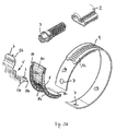
図1A、図2A、図3A及び図5Aの分解図は、ストラップ1、又はストラップの周囲に沿ってストラップ1に設けられた間隙に挿入される別個のばねエレメント5を有するホースクランプを示している。
The exploded views of FIGS. 1A, 2A, 3A and 5A show a hose clamp having a strap 1 or a
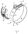
一般的に、全図に示されたホースクランプは、2つの端部若しくは部分1a及び1bを備えるストラップ1を有している。ハウジング2が、例えば締付け又は溶接等によってストラップの部分1aに固定されている。ストラップの端部若しくは部分1bの開放端部1cは部分1aに重なっており、ハウジング2を通過するように案内されており、ハウジング2に配置された駆動可能なねじ3によって駆動される。ねじ3は、ストラップ1の部分1bの開放端部1cの対応する係合領域4に係合するねじ山を有している。この係合領域は、ねじ山を有する領域4として、又は歯又は多数の連続する凹所若しくは開口を有する領域4として形成されている。ハウジング2におけるねじ3を回動させることによって、開放端部1cがハウジング2に対して出し入れされ、これによって、ホースクランプの直径を変化させる。
In general, the hose clamp shown in all figures has a strap 1 with two ends or portions 1a and 1b. The
図1A、図2A、図3A、図4及び図5Aの分解図に示されているように、ストラップの部分1aと1bとの連結部材の形式でばねエレメント5が設けられている。全ての実施形態において、このばねエレメント5は、ばねエレメント5の長さ方向、すなわちストラップ1の周方向に沿って、3つの波形5aとして形成された波形を有している。図示されたばねエレメント5の波形5aの数は発明の範囲を制限しない。波形5aの数は別の実施形態では異なっていてよく、少なくとも1つである。さらに、このばねエレメント5は、実質的にストラップ1の曲率若しくは円周に対応する全体の曲率を有している。
As shown in the exploded views of FIGS. 1A, 2A, 3A, 4 and 5A, a
ばねエレメント5の2つの端部5bは、ストラップの部分1a及び1bに様々な異なる形式で連結されている。図1においては、端部5bは、ストラップの部分1a及び1bの端部の表面に接着又は溶接された平坦な突起である。
The two ends 5b of the
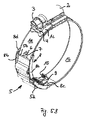
図2及び図5において、端部5bはT字形の突起6であり、各T字形の突起は、ストラップの部分1a及び1bの端部に配置された対応する開口若しくは凹所7に係合している。図3においては、端部5bは、フックを形成する折れ曲がった突起6であり、各突起は、ストラップの部分1a及び1bの端部に配置された対応する開口若しくは凹所7に係合している。図4においては、ばねエレメント5はストラップ1と一体に形成されている。
2 and 5, the
図示された全ての実施形態において、さらに、ホースクランプの内側においてばねエレメント5に隣接した案内エレメント8が設けられている。案内エレメント8は、ばねエレメント5と摺動可能に接触しているベース面8aを提供しており、このベース面8aはさらに側壁8bを有しており、これによって、ストラップ1の周方向に対して垂直方向の断面でU字形を形成している。この形状によって、ばねエレメント5は案内エレメントと常に接触を保つことができる。さらに、案内エレメント8の全体的な曲率は実質的にストラップ1の曲率に対応している。案内エレメント8の、面8aとは反対側の後面は、さらに、ホース(図示せず)に接触し、ばねエレメント5及びばねエレメントの波形5aに対して締め付けられるホースを保護する。
In all illustrated embodiments, a
案内エレメント8の一方の端部8cはストラップ1に固定されており、案内エレメントの他方の端部8cはストラップ1の端部において摺動する。ストラップ1に沿って摺動できるようにするために、案内エレメント8の端部8cは、ストラップ1、特にストラップ1の部分1a又は1bの周囲を緩く抱持する折れ曲がった突起8dを有している。固定された端部8cは同様の突起8dを有しているが、ストラップ1、特にストラップ1の部分1b又は1aの周囲に緊密に折り曲げられている。突起8dは、側壁8bの端部であってもよい。
One
図5はさらに、案内エレメント8と一体に形成された補助エレメント9を付加的に有する、図2に示されたクランプを示している。補助エレメント9の部分は、ストラップ1に対して垂直方向にかつホース(図示せず)に対して長手方向に延びている。補助エレメント9の端部は3回折り曲げられている。補助エレメント9の自由端部は、ホースの前面と接触する停止面10を形成している。前面と接触することにより、前面とホースクランプとの間の距離が規定される。
FIG. 5 further shows the clamp shown in FIG. 2 additionally having an auxiliary element 9 formed integrally with the
ホースクランプに補助エレメント9を提供することは、図2に示した実施形態に限定されない。補助エレメントは、図示された又は図示されていない全ての実施形態において設けられてよい。 Providing the auxiliary element 9 to the hose clamp is not limited to the embodiment shown in FIG. An auxiliary element may be provided in all embodiments shown or not shown.
概して、ホースクランプを締め付けることによって、ストラップ1の部分1b、特にこの部分の端部1cが、ハウジング2に引き込まれる。ストラップ1の有効長が小さくなり、ばねエレメント5は引き伸ばされ、これにより、付勢力若しくは補償力を提供する。締め付けることにより、このばねエレメントに潜在的なエネルギが貯えられる。この付勢力若しくは貯えられたエネルギは、ホースが老化によって劣化した場合にもホースを締め付けるのを助ける。さらに、ばねエレメント5は、加えられた力が大きすぎる場合に引き伸ばされることによって力制限器として働く。
In general, by tightening the hose clamp, the part 1b of the strap 1, in particular the end 1c of this part, is drawn into the
特定の実施形態に関連して言及された全ての特徴は、この特定の実施形態においてのみ提供されるのではなく、明白に言及されていない場合でも全ての実施形態において提供されてよい。全ての特徴が発明の一部であり、互いにあらゆる関係で組み合わされてもよい。 All features mentioned in connection with a particular embodiment are not provided only in this particular embodiment, but may be provided in all embodiments even if not explicitly mentioned. All features are part of the invention and may be combined in any relationship with each other.
1 ストラップ、 1a,1b 部分、 2 ハウジング、 3 ねじ、 4 領域、 5 ばねエレメント、 5a 波、 5b 端部、 6 突起、 7 係合開口、 8 案内エレメント、 8a ベース面、 8b 側壁、 8c 端部、 8d 突起、 9 補助エレメント、 10 停止面
1 strap, 1a, 1b part, 2 housing, 3 screw, 4 region, 5 spring element, 5a wave, 5b end, 6 protrusion, 7 engagement opening, 8 guide element, 8a base surface, 8b side wall,
Claims (14)
前記ばねエレメント(5)の自由端部が、ポジティブロック又は形状閉鎖リンクによって、前記ばねエレメント(5)の端部(5b)に設けられた少なくとも1つの連結部分若しくはエレメント(6)が前記ストラップ(1)の端部若しくは部分(1a,1b)に設けられた対応する連結部分若しくはエレメント(7)に連結されることによって、前記ストラップ(1)の一方の部分若しくは端部(1a,1b)に連結されており、前記ばねエレメント(5)が波形に形成され、周方向で前記ストラップ(1)の間隙に挿入されることを特徴とする、ホースクランプ。 A hose clamp comprising a flexible strap (1) disposed around the hose and a mechanism (2, 3) for increasing or decreasing the effective length of the strap (1), The mechanism (2, 3) is fixed to one end (1a) of the strap (1) and drives the other end (1b, 1c) of the strap (1). 1) at least one part or region is formed as a spring element (5), which provides a spring force in the circumferential direction of the strap (1), the spring element (5) A hose clamp formed as a separate element inserted into the strap (1) between the fixed end (1a) of the strap (1) and the driven end (1b, 1c) ,
At least one connecting part or element (6) provided at the end (5b) of the spring element (5) is connected to the strap (5) by a positive lock or a shape closure link, the free end of the spring element (5). 1) by being connected to a corresponding connecting part or element (7) provided at the end or part (1a, 1b) of the strap (1) to one part or end (1a, 1b) of the strap (1). Hose clamp, characterized in that it is connected and the spring element (5) is formed in a wave shape and is inserted into the gap of the strap (1) in the circumferential direction .
Applications Claiming Priority (5)
| Application Number | Priority Date | Filing Date | Title |
|---|---|---|---|
| EP07021839.1 | 2007-11-09 | ||
| EP07021839 | 2007-11-09 | ||
| EP07021980.3 | 2007-11-13 | ||
| EP07021980A EP2058575B1 (en) | 2007-11-09 | 2007-11-13 | Hose clamp |
| PCT/IB2008/003763 WO2009060313A1 (en) | 2007-11-09 | 2008-10-31 | Hose clamp |
Publications (2)
| Publication Number | Publication Date |
|---|---|
| JP2011503467A JP2011503467A (en) | 2011-01-27 |
| JP5542679B2 true JP5542679B2 (en) | 2014-07-09 |
Family
ID=39030836
Family Applications (1)
| Application Number | Title | Priority Date | Filing Date |
|---|---|---|---|
| JP2010532676A Expired - Fee Related JP5542679B2 (en) | 2007-11-09 | 2008-10-31 | Hose clamp |
Country Status (8)
| Country | Link |
|---|---|
| US (1) | US8607420B2 (en) |
| EP (1) | EP2058575B1 (en) |
| JP (1) | JP5542679B2 (en) |
| KR (1) | KR101616489B1 (en) |
| CN (1) | CN101855487B (en) |
| DE (1) | DE202007019445U1 (en) |
| ES (1) | ES2389133T3 (en) |
| WO (1) | WO2009060313A1 (en) |
Families Citing this family (21)
| Publication number | Priority date | Publication date | Assignee | Title |
|---|---|---|---|---|
| US20060170215A1 (en) * | 2002-11-29 | 2006-08-03 | Martin Cousineau | Hose clamp |
| KR101224058B1 (en) * | 2010-06-11 | 2013-01-18 | (주)동아금속 | Hose clamp |
| WO2012037271A1 (en) * | 2010-09-14 | 2012-03-22 | Band-It-Idex, Inc. | Band clamp tensioning tool |
| KR101300824B1 (en) * | 2011-02-07 | 2013-08-29 | (주)동아금속 | Hose clamp |
| EP2541117B1 (en) * | 2011-06-29 | 2014-10-22 | Dong-A Metal Co., Ltd. | Hose clamp |
| US8650719B2 (en) | 2011-07-21 | 2014-02-18 | Ideal Clamp Products, Inc. | Hose clamp with flat spring liner |
| US8677571B2 (en) * | 2011-07-21 | 2014-03-25 | Ideal Clamp Products, Inc. | Hose clamp with rippled spring liner |
| JP6184596B2 (en) | 2013-06-24 | 2017-08-23 | ダウ グローバル テクノロジーズ エルエルシー | Reinforced polypropylene composition |
| JP6272195B2 (en) * | 2014-09-24 | 2018-01-31 | 株式会社ミハマ | Method for producing elastic structure and method for producing fastening band |
| WO2016065195A1 (en) * | 2014-10-23 | 2016-04-28 | Thomas & Betts International, Llc | Anti-slip tie with wave springs |
| US10588441B2 (en) | 2015-11-19 | 2020-03-17 | Thomas Victor Gariti | Support stand assembly |
| DE102015120509A1 (en) * | 2015-11-26 | 2017-06-01 | Norma Germany Gmbh | hose clamp |
| DE102016109548A1 (en) | 2016-05-24 | 2017-11-30 | Norma Germany Gmbh | hose clamp |
| FR3059059B1 (en) | 2016-11-23 | 2019-11-01 | Financiere De Beaumont - Fdb | DEVICE FOR ARRANGING AN ELEMENT ON A DUCT FOR IMMERING, SUBMERSIBLE ASSEMBLY, INSTALLATION AND METHOD FOR IMPLEMENTING THE SAME |
| DE102017110629B4 (en) * | 2017-05-16 | 2021-05-20 | Norma Germany Gmbh | Positioning device for a spring band clamp |
| US20180340557A1 (en) * | 2017-05-26 | 2018-11-29 | Ideal Clamp Products, Inc. | Hose clamp with indicator |
| US10823208B2 (en) * | 2017-10-09 | 2020-11-03 | Clamp-It LLC | Band clamp |
| WO2019099640A1 (en) | 2017-11-15 | 2019-05-23 | Ideal Clamp Products, Inc. | Hose clamp with spring liner and method |
| US20220364673A1 (en) * | 2021-05-13 | 2022-11-17 | Lincoln Industries, Inc. | Clamp insulation systems and methods |
| US11920711B2 (en) * | 2021-10-26 | 2024-03-05 | Barney Zinter | Hose clamp with pawl and related methods |
| US11598459B1 (en) * | 2021-10-26 | 2023-03-07 | Barney Zinter | Clamp pawl device |
Family Cites Families (27)
| Publication number | Priority date | Publication date | Assignee | Title |
|---|---|---|---|---|
| US198044A (en) * | 1877-12-11 | Improvement in burglar-alarms | ||
| US1138064A (en) * | 1913-10-01 | 1915-05-04 | American Arch Co | Oil-burning locomotive. |
| GB1138064A (en) * | 1965-08-25 | 1968-12-27 | Bell S Asbestos And Engineerin | Improvements in band clamp assemblies for hoses and the like |
| JPS475554Y1 (en) * | 1966-03-10 | 1972-02-26 | ||
| JPS5247830U (en) * | 1975-10-01 | 1977-04-05 | ||
| US4315348A (en) * | 1979-05-08 | 1982-02-16 | Hans Oetiker | Mechanical lock for clamps |
| JPS5648897A (en) * | 1979-09-25 | 1981-05-02 | Nitsusui Seiyaku Kk | Selective isolation medium for cholera bacillus |
| US4308648A (en) * | 1980-03-31 | 1982-01-05 | Murray Corporation | Convoluted hose clamps |
| SE443435B (en) * | 1984-01-30 | 1986-02-24 | Allmaenna Brandredskapsaffaere | HOSE CLAMP DEVICE |
| US5437081A (en) * | 1984-06-20 | 1995-08-01 | Hans Oetiker Ag Maschinen-Und Apparate-Fabrik | Hose clamp |
| DE3601815C2 (en) * | 1985-12-07 | 1993-11-04 | Franz Mueller | PIPE CLAMP |
| JPS62196412A (en) * | 1985-12-07 | 1987-08-29 | フランツ・ミユラ− | Pipe clamping clamp |
| JPH0512553Y2 (en) * | 1988-03-03 | 1993-03-31 | ||
| JPH0645117Y2 (en) * | 1988-04-07 | 1994-11-16 | 中央発條株式会社 | Hose clamp |
| DE4005631A1 (en) * | 1990-02-22 | 1991-09-05 | Rasmussen Gmbh | HOSE CLAMP |
| JPH0726712B2 (en) * | 1991-08-16 | 1995-03-29 | ラスムッセン ジイエムビイエイチ | Hose clip |
| FR2702028B1 (en) * | 1993-02-26 | 1995-05-24 | Caillau Ets | Spring clamp, with improved safety. |
| DE19533553C2 (en) * | 1995-09-11 | 1998-01-29 | Rasmussen Gmbh | Device for clamping a hose end section pushed onto a pipe end section |
| DE19538819C2 (en) * | 1995-10-19 | 1998-04-16 | Rasmussen Gmbh | Hose clamp |
| GB0122191D0 (en) * | 2001-09-14 | 2001-10-31 | Steadman William D | Securing arrangement |
| US20030159255A1 (en) * | 2002-02-28 | 2003-08-28 | Senovich Craig A. | Clamp retention device |
| US6824169B2 (en) * | 2002-11-14 | 2004-11-30 | Dayco Products, Llc | Hose and clamp assembly, clamp subassembly and method |
| DE10349527B4 (en) * | 2003-10-22 | 2009-04-23 | Veritas Ag | Hose and clamp fixation for this hose |
| CN100467929C (en) * | 2005-04-27 | 2009-03-11 | 鲁东大学 | Identical-intensity flexible piping joint clasp and its production |
| US7389568B2 (en) * | 2005-07-27 | 2008-06-24 | Epicor Industries, Inc. | Compression hose clamp |
| DE102006048344B4 (en) * | 2006-10-12 | 2009-10-08 | Norma Germany Gmbh | hose clamp |
| US7589568B2 (en) * | 2007-05-04 | 2009-09-15 | Microchip Technology Incorporated | Variable power and response time brown-out-reset circuit |
-
2007
- 2007-11-13 DE DE202007019445U patent/DE202007019445U1/en not_active Expired - Lifetime
- 2007-11-13 ES ES07021980T patent/ES2389133T3/en active Active
- 2007-11-13 EP EP07021980A patent/EP2058575B1/en not_active Not-in-force
-
2008
- 2008-10-31 WO PCT/IB2008/003763 patent/WO2009060313A1/en active Application Filing
- 2008-10-31 CN CN2008801151923A patent/CN101855487B/en not_active Expired - Fee Related
- 2008-10-31 KR KR1020107010178A patent/KR101616489B1/en active IP Right Grant
- 2008-10-31 US US12/678,607 patent/US8607420B2/en not_active Expired - Fee Related
- 2008-10-31 JP JP2010532676A patent/JP5542679B2/en not_active Expired - Fee Related
Also Published As
| Publication number | Publication date |
|---|---|
| DE202007019445U1 (en) | 2012-08-09 |
| WO2009060313A1 (en) | 2009-05-14 |
| EP2058575B1 (en) | 2012-06-06 |
| CN101855487B (en) | 2012-12-26 |
| ES2389133T3 (en) | 2012-10-23 |
| US8607420B2 (en) | 2013-12-17 |
| JP2011503467A (en) | 2011-01-27 |
| US20100281655A1 (en) | 2010-11-11 |
| CN101855487A (en) | 2010-10-06 |
| KR20100096080A (en) | 2010-09-01 |
| KR101616489B1 (en) | 2016-04-28 |
| EP2058575A1 (en) | 2009-05-13 |
Similar Documents
| Publication | Publication Date | Title |
|---|---|---|
| JP5542679B2 (en) | Hose clamp | |
| JP4645589B2 (en) | Joining assembly with tube socket of fluid retaining parts to be joined | |
| JP3731561B2 (en) | Pipe clamps, especially pipe fittings | |
| US7302741B2 (en) | Hose clamp and spring liner | |
| JP2008095960A (en) | Hose clamp | |
| JP5739392B2 (en) | Profiled clamp with sealing element | |
| JP6800791B2 (en) | Hose clamp with flat spring liner | |
| JP2687954B2 (en) | Fixing device for the hose part pushed into the pipe part | |
| JPH11315981A (en) | Clip | |
| JPH0262758B2 (en) | ||
| JPH05209699A (en) | Hose clip | |
| JPH1137368A (en) | Clamp device for tightly fastening hose onto pipe | |
| US5706558A (en) | Hose clamp | |
| JP2755258B2 (en) | One piece housing for worm driven hose clamp | |
| KR100358259B1 (en) | Earless, stepless clamp structure | |
| KR20140078703A (en) | Hose clamp | |
| JP7411801B2 (en) | hose clamp | |
| JP3945469B2 (en) | Hose clamp and hose connection to pre-position hose clamp | |
| CN100497047C (en) | Clamping ring for fastening a gas generating cartridge | |
| KR200395248Y1 (en) | Pipe Coupling | |
| JP2007016990A (en) | Structure of holding hose clamp | |
| JP4063274B2 (en) | Hose coupling | |
| US20050189767A1 (en) | Spacer for putting into place on a tubular element | |
| JP7473276B2 (en) | Hose Fixtures | |
| KR20210136137A (en) | Locator systems and methods for hose clamps |
Legal Events
| Date | Code | Title | Description |
|---|---|---|---|
| RD04 | Notification of resignation of power of attorney |
Free format text: JAPANESE INTERMEDIATE CODE: A7424 Effective date: 20101228 |
|
| A621 | Written request for application examination |
Free format text: JAPANESE INTERMEDIATE CODE: A621 Effective date: 20110831 |
|
| A977 | Report on retrieval |
Free format text: JAPANESE INTERMEDIATE CODE: A971007 Effective date: 20130212 |
|
| A131 | Notification of reasons for refusal |
Free format text: JAPANESE INTERMEDIATE CODE: A131 Effective date: 20130222 |
|
| A601 | Written request for extension of time |
Free format text: JAPANESE INTERMEDIATE CODE: A601 Effective date: 20130522 |
|
| A602 | Written permission of extension of time |
Free format text: JAPANESE INTERMEDIATE CODE: A602 Effective date: 20130529 |
|
| A601 | Written request for extension of time |
Free format text: JAPANESE INTERMEDIATE CODE: A601 Effective date: 20130624 |
|
| A602 | Written permission of extension of time |
Free format text: JAPANESE INTERMEDIATE CODE: A602 Effective date: 20130701 |
|
| A521 | Written amendment |
Free format text: JAPANESE INTERMEDIATE CODE: A523 Effective date: 20130722 |
|
| A131 | Notification of reasons for refusal |
Free format text: JAPANESE INTERMEDIATE CODE: A131 Effective date: 20130902 |
|
| A601 | Written request for extension of time |
Free format text: JAPANESE INTERMEDIATE CODE: A601 Effective date: 20131128 |
|
| A602 | Written permission of extension of time |
Free format text: JAPANESE INTERMEDIATE CODE: A602 Effective date: 20131209 |
|
| A601 | Written request for extension of time |
Free format text: JAPANESE INTERMEDIATE CODE: A601 Effective date: 20131227 |
|
| A602 | Written permission of extension of time |
Free format text: JAPANESE INTERMEDIATE CODE: A602 Effective date: 20140114 |
|
| A601 | Written request for extension of time |
Free format text: JAPANESE INTERMEDIATE CODE: A601 Effective date: 20140203 |
|
| A602 | Written permission of extension of time |
Free format text: JAPANESE INTERMEDIATE CODE: A602 Effective date: 20140210 |
|
| A521 | Written amendment |
Free format text: JAPANESE INTERMEDIATE CODE: A523 Effective date: 20140214 |
|
| TRDD | Decision of grant or rejection written | ||
| A01 | Written decision to grant a patent or to grant a registration (utility model) |
Free format text: JAPANESE INTERMEDIATE CODE: A01 Effective date: 20140407 |
|
| A61 | First payment of annual fees (during grant procedure) |
Free format text: JAPANESE INTERMEDIATE CODE: A61 Effective date: 20140507 |
|
| R150 | Certificate of patent or registration of utility model |
Ref document number: 5542679 Country of ref document: JP Free format text: JAPANESE INTERMEDIATE CODE: R150 |
|
| R250 | Receipt of annual fees |
Free format text: JAPANESE INTERMEDIATE CODE: R250 |
|
| R250 | Receipt of annual fees |
Free format text: JAPANESE INTERMEDIATE CODE: R250 |
|
| R250 | Receipt of annual fees |
Free format text: JAPANESE INTERMEDIATE CODE: R250 |
|
| R250 | Receipt of annual fees |
Free format text: JAPANESE INTERMEDIATE CODE: R250 |
|
| LAPS | Cancellation because of no payment of annual fees |