JP5803641B2 - Electronic blood pressure monitor - Google Patents
Electronic blood pressure monitor Download PDFInfo
- Publication number
- JP5803641B2 JP5803641B2 JP2011269908A JP2011269908A JP5803641B2 JP 5803641 B2 JP5803641 B2 JP 5803641B2 JP 2011269908 A JP2011269908 A JP 2011269908A JP 2011269908 A JP2011269908 A JP 2011269908A JP 5803641 B2 JP5803641 B2 JP 5803641B2
- Authority
- JP
- Japan
- Prior art keywords
- signal
- circuit
- level
- pulse signal
- drive
- Prior art date
- Legal status (The legal status is an assumption and is not a legal conclusion. Google has not performed a legal analysis and makes no representation as to the accuracy of the status listed.)
- Active
Links
- 230000036772 blood pressure Effects 0.000 title claims description 21
- 238000005259 measurement Methods 0.000 claims description 7
- 230000007274 generation of a signal involved in cell-cell signaling Effects 0.000 claims description 6
- 230000004044 response Effects 0.000 claims description 3
- 230000001934 delay Effects 0.000 claims description 2
- 238000007493 shaping process Methods 0.000 claims description 2
- 238000000034 method Methods 0.000 description 18
- 238000010586 diagram Methods 0.000 description 12
- 230000000630 rising effect Effects 0.000 description 8
- 230000007704 transition Effects 0.000 description 8
- 230000008859 change Effects 0.000 description 6
- 230000010355 oscillation Effects 0.000 description 6
- 208000024172 Cardiovascular disease Diseases 0.000 description 5
- 230000004048 modification Effects 0.000 description 5
- 238000012986 modification Methods 0.000 description 5
- 230000003111 delayed effect Effects 0.000 description 4
- 208000006011 Stroke Diseases 0.000 description 3
- 230000007246 mechanism Effects 0.000 description 3
- 238000012545 processing Methods 0.000 description 3
- 206010020772 Hypertension Diseases 0.000 description 2
- 230000004913 activation Effects 0.000 description 2
- 210000004712 air sac Anatomy 0.000 description 2
- 238000009530 blood pressure measurement Methods 0.000 description 2
- 238000013461 design Methods 0.000 description 2
- 230000005284 excitation Effects 0.000 description 2
- 206010019280 Heart failures Diseases 0.000 description 1
- 230000005856 abnormality Effects 0.000 description 1
- 210000004204 blood vessel Anatomy 0.000 description 1
- 238000004364 calculation method Methods 0.000 description 1
- 230000001364 causal effect Effects 0.000 description 1
- 230000000052 comparative effect Effects 0.000 description 1
- 230000000295 complement effect Effects 0.000 description 1
- 238000013500 data storage Methods 0.000 description 1
- 238000001514 detection method Methods 0.000 description 1
- 238000003745 diagnosis Methods 0.000 description 1
- 230000036541 health Effects 0.000 description 1
- 208000019622 heart disease Diseases 0.000 description 1
- 239000004973 liquid crystal related substance Substances 0.000 description 1
- 208000010125 myocardial infarction Diseases 0.000 description 1
- 230000008569 process Effects 0.000 description 1
- 238000011160 research Methods 0.000 description 1
- 238000012502 risk assessment Methods 0.000 description 1
- 208000024891 symptom Diseases 0.000 description 1
- 230000002618 waking effect Effects 0.000 description 1
- 238000004804 winding Methods 0.000 description 1
- 210000000707 wrist Anatomy 0.000 description 1
Images


Classifications
-
- A—HUMAN NECESSITIES
- A61—MEDICAL OR VETERINARY SCIENCE; HYGIENE
- A61B—DIAGNOSIS; SURGERY; IDENTIFICATION
- A61B5/00—Measuring for diagnostic purposes; Identification of persons
- A61B5/02—Detecting, measuring or recording pulse, heart rate, blood pressure or blood flow; Combined pulse/heart-rate/blood pressure determination; Evaluating a cardiovascular condition not otherwise provided for, e.g. using combinations of techniques provided for in this group with electrocardiography or electroauscultation; Heart catheters for measuring blood pressure
- A61B5/021—Measuring pressure in heart or blood vessels
- A61B5/022—Measuring pressure in heart or blood vessels by applying pressure to close blood vessels, e.g. against the skin; Ophthalmodynamometers
- A61B5/02225—Measuring pressure in heart or blood vessels by applying pressure to close blood vessels, e.g. against the skin; Ophthalmodynamometers using the oscillometric method
-
- A—HUMAN NECESSITIES
- A61—MEDICAL OR VETERINARY SCIENCE; HYGIENE
- A61B—DIAGNOSIS; SURGERY; IDENTIFICATION
- A61B5/00—Measuring for diagnostic purposes; Identification of persons
- A61B5/02—Detecting, measuring or recording pulse, heart rate, blood pressure or blood flow; Combined pulse/heart-rate/blood pressure determination; Evaluating a cardiovascular condition not otherwise provided for, e.g. using combinations of techniques provided for in this group with electrocardiography or electroauscultation; Heart catheters for measuring blood pressure
- A61B5/021—Measuring pressure in heart or blood vessels
- A61B5/022—Measuring pressure in heart or blood vessels by applying pressure to close blood vessels, e.g. against the skin; Ophthalmodynamometers
- A61B5/02233—Occluders specially adapted therefor
-
- A—HUMAN NECESSITIES
- A61—MEDICAL OR VETERINARY SCIENCE; HYGIENE
- A61B—DIAGNOSIS; SURGERY; IDENTIFICATION
- A61B5/00—Measuring for diagnostic purposes; Identification of persons
- A61B5/02—Detecting, measuring or recording pulse, heart rate, blood pressure or blood flow; Combined pulse/heart-rate/blood pressure determination; Evaluating a cardiovascular condition not otherwise provided for, e.g. using combinations of techniques provided for in this group with electrocardiography or electroauscultation; Heart catheters for measuring blood pressure
- A61B5/021—Measuring pressure in heart or blood vessels
- A61B5/022—Measuring pressure in heart or blood vessels by applying pressure to close blood vessels, e.g. against the skin; Ophthalmodynamometers
- A61B5/0225—Measuring pressure in heart or blood vessels by applying pressure to close blood vessels, e.g. against the skin; Ophthalmodynamometers the pressure being controlled by electric signals, e.g. derived from Korotkoff sounds
- A61B5/02255—Measuring pressure in heart or blood vessels by applying pressure to close blood vessels, e.g. against the skin; Ophthalmodynamometers the pressure being controlled by electric signals, e.g. derived from Korotkoff sounds the pressure being controlled by plethysmographic signals, e.g. derived from optical sensors
-
- H—ELECTRICITY
- H10—SEMICONDUCTOR DEVICES; ELECTRIC SOLID-STATE DEVICES NOT OTHERWISE PROVIDED FOR
- H10N—ELECTRIC SOLID-STATE DEVICES NOT OTHERWISE PROVIDED FOR
- H10N30/00—Piezoelectric or electrostrictive devices
- H10N30/80—Constructional details
- H10N30/802—Circuitry or processes for operating piezoelectric or electrostrictive devices not otherwise provided for, e.g. drive circuits
-
- H—ELECTRICITY
- H02—GENERATION; CONVERSION OR DISTRIBUTION OF ELECTRIC POWER
- H02H—EMERGENCY PROTECTIVE CIRCUIT ARRANGEMENTS
- H02H9/00—Emergency protective circuit arrangements for limiting excess current or voltage without disconnection
- H02H9/001—Emergency protective circuit arrangements for limiting excess current or voltage without disconnection limiting speed of change of electric quantities, e.g. soft switching on or off
- H02H9/002—Emergency protective circuit arrangements for limiting excess current or voltage without disconnection limiting speed of change of electric quantities, e.g. soft switching on or off limiting inrush current on switching on of inductive loads subjected to remanence, e.g. transformers
Landscapes
- Health & Medical Sciences (AREA)
- Life Sciences & Earth Sciences (AREA)
- Vascular Medicine (AREA)
- Cardiology (AREA)
- Biomedical Technology (AREA)
- Molecular Biology (AREA)
- Physiology (AREA)
- Biophysics (AREA)
- Pathology (AREA)
- Engineering & Computer Science (AREA)
- Ophthalmology & Optometry (AREA)
- Heart & Thoracic Surgery (AREA)
- Medical Informatics (AREA)
- Physics & Mathematics (AREA)
- Surgery (AREA)
- Animal Behavior & Ethology (AREA)
- General Health & Medical Sciences (AREA)
- Public Health (AREA)
- Veterinary Medicine (AREA)
- Dentistry (AREA)
- Measuring Pulse, Heart Rate, Blood Pressure Or Blood Flow (AREA)
Description
この発明は、電子血圧計に関し、特に圧電ポンプで空気袋を加圧等することで血圧を測定する電子血圧計に関する。 The present invention relates to an electronic sphygmomanometer, and more particularly to an electronic sphygmomanometer that measures blood pressure by pressurizing an air bag with a piezoelectric pump.
血圧は循環器疾患を解析する指標の一つである。血圧に基づいて循環器疾患のリスク解析を行なうことは、たとえば脳卒中や心不全や心筋梗塞などの心血管系の疾患の予防に有効である。特に、早朝に血圧が上昇する早朝高血圧は心臓病や脳卒中などに関係している。さらに、早朝高血圧の中でも、モーニングサージと呼ばれる起床後1時間から1時間半ぐらいの間に急激に血圧が上昇する症状は、脳卒中との因果関係があることが判明している。そこで、時間(生活習慣)と血圧変化の相互関係を把握することが、心血管系の疾患のリスク解析に有用である。したがって、長期間にわたり、連続的に血圧測定することが必要となってきている。 Blood pressure is one index for analyzing cardiovascular diseases. Analyzing the risk of cardiovascular disease based on blood pressure is effective in preventing cardiovascular diseases such as stroke, heart failure and myocardial infarction. In particular, early morning hypertension, in which blood pressure rises in the early morning, is related to heart disease and stroke. Furthermore, it has been found that, among early morning hypertension, a symptom of a sudden rise in blood pressure between 1 hour and 1.5 hours after waking up, called morning surge, has a causal relationship with stroke. Thus, grasping the correlation between time (lifestyle) and blood pressure change is useful for risk analysis of cardiovascular diseases. Therefore, it is necessary to continuously measure blood pressure over a long period of time.
また、近年の研究成果により、病院や健康診断時に測定する血圧(随時血圧)よりも、家庭で測定した家庭血圧が、より心血管系疾患の予防・診断・治療に有効であることが判明してきている。これにともない、家庭向け血圧計が広く普及し、家庭血圧値を診断に使用する動きも始まっており、種々の家庭向け血圧計がある。 In addition, recent research results have shown that home blood pressure measured at home is more effective in preventing, diagnosing, and treating cardiovascular diseases than blood pressure measured during hospitals and health examinations (advanced blood pressure). ing. Along with this, home-use sphygmomanometers have become widespread, and the use of home blood pressure values for diagnosis has started, and there are various home-use sphygmomanometers.
一般的な電子血圧計は、空気袋を内蔵した腕帯を生体の一部に均等に巻き付け、その空気袋を空気により加減圧することにより、圧迫された動脈血管の容積変化を空気袋圧力(カフ圧)変動の振幅変化として捕らえ、血圧算出するオシロメトリック法を用いた電子血圧計が用いられており、例えば、特開2009−74418号公報のような圧電ポンプを用いて加圧することが可能である。 A typical electronic sphygmomanometer wraps an armband with a bladder in it evenly around a part of a living body, and pressurizes and depressurizes the bladder with air, thereby reducing the volume change of the compressed arterial blood vessel. An electronic sphygmomanometer that uses an oscillometric method to capture blood pressure as a change in amplitude of cuff pressure) is used. For example, it is possible to apply pressure using a piezoelectric pump such as that disclosed in Japanese Patent Application Laid-Open No. 2009-74418. It is.
一方で、当該圧電ポンプを駆動する方式として、他励振方式と自励振方式があるが、自励振方式の場合、回路の設計誤差等に起因してパルスの出力特性を微調整する必要があり、当該微調整のための回路を設ける場合、回路のレイアウト等が大きくなるという問題がある。 On the other hand, as a method of driving the piezoelectric pump, there are a separate excitation method and a self-excitation method, but in the case of the self-excitation method, it is necessary to finely adjust the pulse output characteristics due to a circuit design error, etc. When a circuit for the fine adjustment is provided, there is a problem that a circuit layout becomes large.
他励振方式の場合、例えばCPUから圧電ポンプの特性に合わせたパルスを出力すれば良く設計が容易である。そして、そのパルスをHブリッジ回路等により、圧電ポンプに印加する方式が採用されている。この場合、Hブリッジ回路等のスイッチング時に信号を反転させるため、圧電ポンプに蓄積された電荷と反転した信号入力によって、大きな突入電流が流れることが知られている。 In the case of the separate excitation method, for example, a pulse that matches the characteristics of the piezoelectric pump may be output from the CPU, and the design is easy. And the system which applies the pulse to a piezoelectric pump by H bridge circuit etc. is adopted. In this case, since the signal is inverted at the time of switching of the H bridge circuit or the like, it is known that a large inrush current flows due to the charge accumulated in the piezoelectric pump and the inverted signal input.
当該突入電流は、電池電圧の降下を引き起こすことになり、血圧測定の精度に影響を及ぼす可能性がある。また、血圧計の電池寿命が短くなるという問題もある。 The inrush current causes a drop in battery voltage, which may affect blood pressure measurement accuracy. There is also a problem that the battery life of the sphygmomanometer is shortened.
本発明は、上記のような問題を解決するためになされたものであって、突入電流を簡易な方式で抑制することが可能な電子血圧計を提供することを目的とする。 The present invention has been made to solve the above-described problems, and an object thereof is to provide an electronic sphygmomanometer capable of suppressing an inrush current by a simple method.
本発明のある局面に従う電子血圧計は、測定部位に装着するカフと、カフに加える圧力を調整する圧電ポンプと、圧電ポンプを駆動する駆動回路と、圧電ポンプの駆動タイミングを規定するパルス信号を駆動回路に出力するコントローラとを備える。駆動回路は、第1および第2駆動信号にそれぞれ応答して圧電ポンプの両端にそれぞれ印加する電圧の接続関係を切り替えるためのスイッチング回路と、コントローラから出力されたパルス信号に基づいて第1および第2駆動信号を出力する信号生成回路とを含む。信号生成回路は、第1および第2駆動信号の位相が重ならないようにタイミングを調整する信号調整回路を有する。 An electronic sphygmomanometer according to an aspect of the present invention includes a cuff attached to a measurement site, a piezoelectric pump that adjusts pressure applied to the cuff, a drive circuit that drives the piezoelectric pump, and a pulse signal that defines drive timing of the piezoelectric pump. A controller for outputting to the drive circuit. The drive circuit is responsive to the first and second drive signals to switch the connection relationship of the voltages applied to both ends of the piezoelectric pump, respectively, and the first and second based on the pulse signal output from the controller. And a signal generation circuit that outputs two drive signals. The signal generation circuit includes a signal adjustment circuit that adjusts timing so that the phases of the first and second drive signals do not overlap.
好ましくは、信号生成回路は、パルス信号を反転させた反転パルス信号を出力する反転回路をさらに含み、信号調整回路は、パルス信号および反転パルス信号の少なくとも一方のデューティ比を調整する。 Preferably, the signal generation circuit further includes an inverting circuit that outputs an inverted pulse signal obtained by inverting the pulse signal, and the signal adjustment circuit adjusts a duty ratio of at least one of the pulse signal and the inverted pulse signal.
特に、信号調整回路は、信号の位相を遅延させる遅延回路と、波形整形回路とを有する。 In particular, the signal adjustment circuit includes a delay circuit that delays the phase of the signal and a waveform shaping circuit.
特に、遅延回路は、抵抗素子と、容量素子とで構成される。
特に、抵抗素子は、外部からの指示に従って抵抗値が変化する可変抵抗素子である。
In particular, the delay circuit includes a resistance element and a capacitance element.
In particular, the resistance element is a variable resistance element whose resistance value changes according to an instruction from the outside.
特に、容量素子は、外部からの指示に従って容量成分が変化する可変容量素子である。 In particular, the capacitive element is a variable capacitive element whose capacitance component changes according to an instruction from the outside.
突入電流を簡易な方式で抑制することが可能である。 Inrush current can be suppressed by a simple method.
以下、この発明に基づいた実施の形態における電子血圧計について図面を参照して詳細に説明する。なお、以下に説明する実施の形態において、個数、量などに言及する場合、特に記載がある場合を除き、本発明の範囲は必ずしもその個数、量などに限定されない。また、以下に複数の実施の形態が存在する場合、特に記載がある場合を除き、各々の実施の形態の構成を適宜組み合わせることは、当初から予定されている。各図中、同一符号は同一または相当部分を指し、重複する説明は繰返さない場合がある。 Hereinafter, an electronic blood pressure monitor according to an embodiment based on the present invention will be described in detail with reference to the drawings. Note that in the embodiments described below, when referring to the number, amount, and the like, the scope of the present invention is not necessarily limited to the number, amount, and the like unless otherwise specified. In addition, when there are a plurality of embodiments below, it is planned from the beginning to appropriately combine the configurations of the embodiments unless otherwise specified. In the drawings, the same reference numerals indicate the same or corresponding parts, and redundant description may not be repeated.
本実施の形態では、測定部位を上腕とし、オシロメトリック法で血圧を算出し、一例として圧力センサが1個搭載されている電子血圧計について説明する。なお、血圧算出のために適用される方法は、オシロメトリック法に限定されない。なお、圧力センサの個数は複数個としても良い。 In the present embodiment, an electronic sphygmomanometer will be described in which a blood pressure is calculated by the oscillometric method with the measurement site as the upper arm, and one pressure sensor is mounted as an example. Note that the method applied for blood pressure calculation is not limited to the oscillometric method. The number of pressure sensors may be plural.
(電子血圧計1の外観)
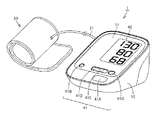
図1は、本発明の実施の形態に従う電子血圧計1の外観について説明する図である。
(Appearance of electronic sphygmomanometer 1)
FIG. 1 is a diagram illustrating an external appearance of an
図2は、本発明の実施の形態に従う電子血圧計1のハードウェア構成を表わすブロック図である。
FIG. 2 is a block diagram representing a hardware configuration of
図1および図2を参照して、電子血圧計1は、本体部10と、表面カバー11と、被測定者の上腕に巻付け可能なカフ20とを備える。カフ20は、空気袋21を含む。表面カバー11には、たとえば液晶などにより構成される表示部40と、ユーザ(被測定者)からの指示を受付けるための複数のスイッチからなる操作部41とが配置されている。
With reference to FIG. 1 and FIG. 2, the
本体部10は、上述の表示部40および操作部41に加え、各部を集中的に制御し各種の演算処理を行なうためのCPU(Central Processing Unit)100と、CPU100に所定の動作をさせるためのプログラムやデータを記憶するための処理用のメモリ42と、測定した血圧データなどを格納するためのデータ格納用のメモリ43と、本体部10の各部に電力を供給するための電池44と、現在時間を計時して計時データをCPU100に出力するタイマ45とを含む。
In addition to the
操作部41は、電源をONまたはOFFするための指示の入力と測定開始および終了の指示を受付ける測定/停止スイッチ41Aと、タイマ45をセットするために操作されるタイマセットスイッチ41Bと、メモリ43に格納された血圧データなどの情報をメモリ43から読出し、表示部40に表示する指示を受付けるためのメモリスイッチ41Cと、タイマセットの際の数字とメモリ呼び出しの際のメモリ番号の上げ下げの指示を受付けるための矢印スイッチ41D,41Eとを有する。
The
本体部10は、さらに、圧電ポンプ51および排気弁(以下、弁という)52を含むカフ圧の調整機構を有する。圧電ポンプ51、弁52および空気袋21内の圧力(カフ圧)を検出するための圧力センサ321からなるエア系は、カフ用エアチューブ31を介して、カフ20に内包される空気袋21と接続される。
The
本体部10は、さらに、上述したエア系と、カフ圧の調整機構と、発振回路331とを含む。カフ圧の調整機構は、圧電ポンプ51および弁52のほか、ポンプ駆動回路53と弁駆動回路54とを有する。
The
圧電ポンプ51は、カフ圧を加圧するために、空気袋21に空気を供給する。弁52は、空気袋21の空気を排出しまたは封入するために開閉される。
The
ポンプ駆動回路53は、圧電ポンプ51の駆動をCPU100から与えられる制御信号(パルス信号)に基づいて制御する。弁駆動回路54は弁52の開閉制御をCPU100から与えられる制御信号に基づいて行なう。
The
圧力センサ321には、一例として静電容量型の圧力センサを用いる。静電容量型の圧力センサは、検出するカフ圧に応じて容量値が変化する。発振回路331は圧力センサ321に接続されて、圧力センサの容量値に基づき発振する。本例においては、発振回路331は、CPU100からの指示に応答して動作し、CPU100は、発振回路331に対して活性化信号を出力する。なお、圧力センサは、静電容量型に限られず、他の方式を採用することも可能である。例えば、ピエゾ抵抗素子を用いたピエゾ抵抗型の圧力センサを採用するようにすることも可能である。
As an example, a capacitance type pressure sensor is used for the
CPU100からの活性化信号を受けた発振回路331は、圧力センサ321の容量値に応じた周波数を有する信号(以下、周波数信号という)を出力する。出力した周波数信号はCPU100に与えられる。
The
CPU100は、発振回路331から入力される周波数信号を圧力に変換することによって、圧力を検知する。
The
図3は、本発明の実施の形態に従うポンプ駆動回路53の構成を説明する図である。
図3を参照して、ポンプ駆動回路53は、反転回路60と、信号調整回路62と、Hブリッジ回路64と、昇圧回路66とを含む。
FIG. 3 is a diagram illustrating a configuration of
Referring to FIG. 3, pump
反転回路60は、CPU100から与えられる制御信号(パルス信号)の入力を受ける。当該制御信号(パルス信号)は、圧電ポンプ51の駆動を規定するためのタイミング信号である。そして、反転回路60は、当該制御信号(パルス信号)の入力に応答して2つの制御信号を出力する。具体的には、一方は、入力されたパルス信号と同位相の信号をそのまま出力し、他方は、パルス信号の位相を反転させた反転パルス信号として出力する。
The inverting
信号調整回路62は、反転回路60から入力されたパルス信号および反転パルス信号をそれぞれ受けて、Hブリッジ回路64を駆動する第1および第2駆動信号としてそれぞれ出力する。具体的には、信号調整回路62は、入力されたパルス信号および反転パルス信号の少なくとも一方のデューティ比を調整して出力する。
The
Hブリッジ回路64は、圧電ポンプ51に所定の電流を供給するスイッチング回路であり、第1および第2駆動信号に従って所定の電流を圧電ポンプ51に供給する。第1の駆動信号に従って圧電ポンプ51に第1の方向(正方向)に電流を供給するように圧電ポンプ51の両端に電圧を印加する。また、第2の駆動信号に従って圧電ポンプ51に第1の方向と反対の第2の方向(負方向)に電流を供給するように圧電ポンプ51の両端に電圧を印加する。すなわち、第1および第2の駆動信号に従って圧電ポンプ51の両端にそれぞれ印加する電圧の接続関係を切り替える(論理を入れ替える)スイッチング制御を実行する。具体的には、圧電ポンプ51に印加する電圧の一方の側を高電圧として他方の側を低電圧とし、当該電圧の接続関係を第1および第2の駆動信号に従って切り替える。
The
昇圧回路66は、CPU100からの指示に従ってHブリッジ回路64に供給する印加電圧のレベルを調整する。印加電圧のレベルを調整することにより圧電ポンプ51に流れる電流量を調整することが可能である。なお、圧電ポンプ51に流れる電流量が一定の場合には、CPU100からの電圧調整の指示は必要ではなく、固定的に所望の電圧に昇圧してHブリッジ回路64に供給すれば良い。なお、電圧を昇圧する必要がなければ特に昇圧回路66を設けない構成とすることも可能である。なお、Hブリッジ回路64および昇圧回路66の構成については、公知の技術であるのでその詳細な説明はしない。
The
図4は、本発明の実施の形態に従う反転回路60および信号調整回路62の具体的構成について説明する図である。
FIG. 4 is a diagram illustrating specific configurations of
図4を参照して、反転回路60は、インバータIV0を含む。反転回路60に入力されたパルス信号は、分岐して一方は、そのまま信号調整回路62に出力され、他方は、インバータIV0を介する反転パルス信号として信号調整回路62に出力される。
Referring to FIG. 4,
信号調整回路62は、インバータIV1,IV2と、NAND回路ND0,ND1と、抵抗素子R0,R1と、容量素子C0,C1とを含む。
NAND回路ND0の一方の入力ノードは、パルス信号の入力を受け、他方の入力ノードは、ローパスフィルタを通過したパルス信号の入力を受ける。ローパスフィルタは、抵抗素子R0と、容量素子C0とで構成される。当該ローパスフィルタを通過したパルス信号は、抵抗素子R0および容量素子C0の抵抗および容量成分に従い信号の立ち上がりおよび立ち下りが鈍る。 One input node of the NAND circuit ND0 receives a pulse signal, and the other input node receives a pulse signal that has passed through a low-pass filter. The low-pass filter includes a resistance element R0 and a capacitance element C0. The pulse signal that has passed through the low-pass filter has a slow rise and fall of the signal according to the resistance and capacitance components of the resistance element R0 and the capacitance element C0.
NAND回路ND0は、一方および他方の入力ノードがともに「H」レベルとなった場合に「L」レベルを出力し、インバータIV1を介して「H」レベルの信号が信号調整回路62から出力される。
NAND circuit ND0 outputs an “L” level when one and the other input nodes both attain “H” level, and an “H” level signal is output from
ここで、当該ローパスフィルタを通過した信号は「H」レベルへの立ち上がりおよび「L」レベルへの立ち下がりが鈍るためNAND回路ND0の内部信号において位相が遅延した状態となる。これによりNAND回路ND0の出力信号の立ち上がりおよび立ち下がりのタイミングが変化する。すなわち、NAND回路ND0の出力信号のデューティ比を調整することが可能となり、結果として信号調整回路62からの出力信号のデューティ比が調整される。
Here, since the signal passing through the low-pass filter does not rise to the “H” level and falls to the “L” level, the phase of the internal signal of the NAND circuit ND0 is delayed. As a result, the rise and fall timings of the output signal of the NAND circuit ND0 change. That is, the duty ratio of the output signal of the NAND circuit ND0 can be adjusted, and as a result, the duty ratio of the output signal from the
同様に、NAND回路ND1の一方の入力ノードは、反転パルス信号の入力を受け、他方の入力ノードは、ローパスフィルタを通過した反転パルス信号の入力を受ける。ローパスフィルタは、抵抗素子R1と、容量素子C1とで構成される。当該ローパスフィルタを通過した反転パルス信号は、抵抗素子R1および容量素子C1の抵抗および容量成分に従い信号の立ち上がりおよび立ち下りが鈍る。 Similarly, one input node of the NAND circuit ND1 receives the input of the inverted pulse signal, and the other input node receives the input of the inverted pulse signal that has passed through the low-pass filter. The low-pass filter includes a resistance element R1 and a capacitance element C1. The rising and falling edges of the inverted pulse signal that has passed through the low-pass filter become dull according to the resistance and capacitance components of the resistance element R1 and the capacitance element C1.
NAND回路ND1は、一方および他方の入力ノードがともに「H」レベルとなった場合に「L」レベルを出力し、インバータIV2を介して「H」レベルの信号が信号調整回路62から出力される。
NAND circuit ND1 outputs an “L” level when one and the other input nodes both attain “H” level, and an “H” level signal is output from
ここで、当該ローパスフィルタを通過した信号は「H」レベルへの立ち上がりおよび「L」レベルへの立ち下がりが鈍るためNAND回路ND1の内部信号において位相が遅延した状態となる。これによりNAND回路ND1の出力信号の立ち上がりおよび立ち下がりのタイミングが変化する。すなわち、NAND回路ND1の出力信号のデューティ比を調整することが可能となり、結果として信号調整回路62からの出力信号のデューティ比が調整される。
Here, since the signal passing through the low-pass filter does not rise to “H” level and falls to “L” level, the phase of the internal signal of the NAND circuit ND1 is delayed. As a result, the rise and fall timings of the output signal of the NAND circuit ND1 change. That is, it becomes possible to adjust the duty ratio of the output signal of the NAND circuit ND1, and as a result, the duty ratio of the output signal from the
図5は、本発明の実施の形態に従う反転回路60および信号調整回路62の入力および出力信号波形を説明する図である。
FIG. 5 is a diagram illustrating input and output signal waveforms of
図5を参照して、CPU100からの一定周期の制御信号(パルス信号)が出力されている場合が示されている。具体的には、時刻t0で「H」レベル、時刻t2で「L」レベル、時刻t4で「H」レベル、時刻t6で「L」レベルに遷移する場合が示されている。
Referring to FIG. 5, a case where a control signal (pulse signal) with a constant period is output from
そして、当該制御信号に従ってNAND回路ND0に入力される入力信号の波形が示されている。NAND回路ND0の内部において、本例においては、一例として、入力される信号波形の振幅が0〜Vccであるものとし、最大振幅の30%以下を「L」レベル、70%以上を「H」レベルとして波形を整形する場合が示されている。 A waveform of an input signal input to the NAND circuit ND0 according to the control signal is shown. In the NAND circuit ND0, in this example, as an example, the amplitude of the input signal waveform is 0 to Vcc, 30% or less of the maximum amplitude is “L” level, and 70% or more is “H”. The case where a waveform is shaped as a level is shown.
ここで、NAND回路ND0の一方の入力ノードに対しては、遅延は生じないためパルス信号と同位相の信号が入力される。すなわち、NAND回路ND0の一方の入力ノードからの信号に従う内部信号A1の立ち上がりおよび立ち下がりは、遅延がないため制御信号と同位相の時刻t0で「H」レベル、時刻t2で「L」レベル、時刻t4で「H」レベル、時刻t6で「L」レベルに遷移する。 Here, a signal having the same phase as the pulse signal is input to one input node of the NAND circuit ND0 because no delay occurs. That is, the rise and fall of the internal signal A1 according to the signal from one input node of the NAND circuit ND0 has no delay, so that it is at the “H” level at the time t0 in phase with the control signal, and at the “L” level at the time t2. It transitions to the “H” level at time t4 and to the “L” level at time t6.
一方、NAND回路ND0の他方の入力ノードに対しては、ローパスフィルタを介した信号が入力されるため波形の信号の立ち上がりおよび立ち下がりが鈍る信号が入力される。すなわち、NAND回路ND0の他方の入力ノードからの信号に従う内部信号B1の立ち上がりおよび立ち下がりは、遅延により制御信号から位相が遅れた時刻t1で「H」レベル、時刻t3で「L」レベル、時刻t5で「H」レベル、時刻t7で「L」レベルに遷移する。 On the other hand, since the signal through the low-pass filter is input to the other input node of the NAND circuit ND0, a signal whose rise and fall of the waveform signal are blunt is input. That is, the rising and falling edges of the internal signal B1 according to the signal from the other input node of the NAND circuit ND0 are “H” level at the time t1 when the phase is delayed from the control signal due to the delay, “L” level at the time t3, It transitions to the “H” level at t5 and to the “L” level at time t7.
NAND回路ND0の出力信号は、内部信号A1およびB1の組み合わせに基づいて出力される。具体的には、内部信号A1およびB1のいずれか一方が「L」レベルである場合に「H」レベルの信号が出力され、ともに「H」レベルである場合に「L」レベルの信号が出力される。 The output signal of NAND circuit ND0 is output based on the combination of internal signals A1 and B1. Specifically, when either one of the internal signals A1 and B1 is at the “L” level, an “H” level signal is output, and when both are at the “H” level, an “L” level signal is output. Is done.
本例においては、インバータIV1に従う反転信号(Hブリッジ回路の入力信号(駆動信号FIN))として、時刻t1で「H」レベル、時刻t2で「L」レベル、時刻t5で「H」レベル、時刻t6で「L」レベルに遷移する。 In this example, as an inverted signal (input signal (drive signal FIN) of the H bridge circuit) according to the inverter IV1, the “H” level at time t1, the “L” level at time t2, the “H” level at time t5, the time Transition to the “L” level at t6.
これにより、信号調整回路62から制御信号(パルス信号)のデューティ比が調整されたHブリッジ回路に入力される駆動信号FINが出力される。
As a result, the drive signal FIN input to the H bridge circuit in which the duty ratio of the control signal (pulse signal) is adjusted is output from the
図6は、本発明の実施の形態に従う反転回路60および信号調整回路62の入力および出力信号波形を説明する別の図である。
FIG. 6 is another diagram illustrating input and output signal waveforms of
図6を参照して、CPU100からの一定周期の制御信号(パルス信号)が出力されている場合が示されている。
Referring to FIG. 6, a case where a control signal (pulse signal) with a constant period is output from
具体的には、時刻t10で「H」レベル、時刻t12で「L」レベル、時刻t14で「H」レベル、時刻t16で「L」レベルに遷移する場合が示されている。 Specifically, there is shown a case where a transition is made to “H” level at time t10, “L” level at time t12, “H” level at time t14, and “L” level at time t16.
また、インバータIV0で反転された反転パルス信号が示されている。
具体的には、時刻t10で「L」レベル、時刻t12で「H」レベル、時刻t14で「L」レベル、時刻t16で「H」レベルに遷移する場合が示されている。
Further, an inverted pulse signal inverted by the inverter IV0 is shown.
Specifically, there is shown a case where a transition is made to the “L” level at time t10, the “H” level at time t12, the “L” level at time t14, and the “H” level at time t16.
そして、当該反転パルス信号に従ってNAND回路ND1に入力される入力信号の波形が示されている。NAND回路ND1の内部において、本例においては、一例として、入力される信号波形の振幅が0〜Vccであるものとし、最大振幅の30%以下を「L」レベル、70%以上を「H」レベルとして波形を整形する場合が示されている。 The waveform of the input signal input to the NAND circuit ND1 according to the inverted pulse signal is shown. In the NAND circuit ND1, in this example, as an example, the amplitude of the input signal waveform is 0 to Vcc, 30% or less of the maximum amplitude is “L” level, and 70% or more is “H”. The case where a waveform is shaped as a level is shown.
ここで、NAND回路ND1の一方の入力ノードに対しては、遅延は生じないため反転パルス信号と同位相の信号が入力される。すなわち、NAND回路ND1の一方の入力ノードからの信号に従う内部信号A2の立ち上がりおよび立ち下がりは、遅延がないため反転パルス信号と同位相の時刻t10で「L」レベル、時刻t12で「H」レベル、時刻t14で「L」レベル、時刻t16で「H」レベルに遷移する。 Here, a signal having the same phase as the inverted pulse signal is input to one input node of the NAND circuit ND1 because no delay occurs. That is, the rise and fall of the internal signal A2 according to the signal from one input node of the NAND circuit ND1 has no delay, so that it is at the “L” level at the time t10 and at the “H” level at the time t12 in phase with the inverted pulse signal. At time t14, the level changes to the “L” level, and at time t16, the level changes to the “H” level.
一方、NAND回路ND0の他方の入力ノードに対しては、ローパスフィルタを介した信号が入力されるため波形の信号の立ち上がりおよび立ち下がりが鈍る信号が入力される。すなわち、NAND回路ND0の他方の入力ノードからの信号に従う内部信号B2の立ち上がりおよび立ち下がりは、遅延により制御信号から位相が遅れた時刻t11で「L」レベル、時刻t13で「H」レベル、時刻t15で「L」レベル、時刻t17で「H」レベルに遷移する。 On the other hand, for the other input node of NAND circuit ND 0, rising and falling becomes dull signal waveform of the signal since the signal through the low-pass filter is input is input. That is, the rising and falling edges of the internal signal B2 according to the signal from the other input node of the NAND circuit ND0 are “L” level at time t11 when the phase is delayed from the control signal due to delay, “H” level at time t13, It transitions to the “L” level at t15 and to the “H” level at time t17.
NAND回路ND1の出力信号は、内部信号A2およびB2の組み合わせに基づいて出力される。具体的には、内部信号A2およびB2のいずれか一方が「L」レベルである場合に「H」レベルの信号が出力され、ともに「H」レベルである場合に「L」レベルの信号が出力される。 The output signal of NAND circuit ND1 is output based on the combination of internal signals A2 and B2. Specifically, when either one of internal signals A2 and B2 is at “L” level, an “H” level signal is output, and when both are at “H” level, an “L” level signal is output. Is done.
本例においては、インバータIV2に従う反転信号(Hブリッジ回路の入力信号(駆動信号RIN))として、時刻t10で「L」レベル、時刻t13で「H」レベル、時刻t14で「L」レベル、時刻t17で「H」レベルに遷移する。 In this example, as an inverted signal (input signal (drive signal RIN) of the H bridge circuit) according to the inverter IV2, the “L” level at time t10, the “H” level at time t13, the “L” level at time t14, and the time Transition to the “H” level at t17.
これにより、信号調整回路62から制御信号(パルス信号)のデューティ比が調整されたHブリッジ回路に入力される駆動信号RINが出力される。
As a result, the drive signal RIN input to the H bridge circuit in which the duty ratio of the control signal (pulse signal) is adjusted is output from the
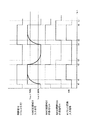
図7は、Hブリッジ回路に駆動信号FINおよびRINが入力される場合の突入電流について説明する図である。 FIG. 7 is a diagram for explaining the inrush current when the drive signals FIN and RIN are input to the H-bridge circuit.
図7(A)を参照して、ここでは、比較例として従来のHブリッジ回路に入力されていた駆動信号の波形が示されている。 Referring to FIG. 7A, here, a waveform of a drive signal input to a conventional H-bridge circuit is shown as a comparative example.
当該図に示されるように、駆動信号FINおよびRINは互いに相補的な論理関係を有しており、駆動信号FINの「H」レベルから「L」レベルの立ち下がりと、駆動信号RINの「L」レベルから「H」レベルの立ち上がりのタイミングがほぼ同時であった。これにより駆動信号FINの「H」レベルから「L」レベルの立下りに起因する突入電流と、駆動信号RINの「L」レベルから「H」レベルの立ち上がりに起因する突入電流とが流れるタイミングが同時になり、全体として突入電流が大きくなるという問題があった。当該突入電流により過大な電圧降下が生じるという問題があった。 As shown in the figure, the drive signals FIN and RIN have a complementary logical relationship with each other, the falling of the drive signal FIN from the “H” level to the “L” level, and the drive signal RIN “L”. The rising timing from the “H” level to the “H” level was almost simultaneous. As a result, the timing at which the inrush current caused by the fall of the drive signal FIN from the “H” level to the “L” level and the inrush current caused by the rise of the drive signal RIN from the “L” level to the “H” level flow. At the same time, there is a problem that the inrush current increases as a whole. There was a problem that an excessive voltage drop was caused by the inrush current.
図7(B)を参照して、ここでは、本例におけるHブリッジ回路に入力される駆動信号の波形が示されている。 Referring to FIG. 7B, here, the waveform of the drive signal input to the H-bridge circuit in this example is shown.
当該図に示されるように、駆動信号FINおよびRINの立ち上がりおよび立ち下がりのタイミングが重ならないように、デューティ比を調整した場合が示されている。これにより、時刻t20における駆動信号FINの「H」レベルから「L」レベルの立ち下がりと、時刻t21における駆動信号RINの「L」レベルから「H」レベルの立ち上がりのタイミングとがずれるため、駆動信号FINの「H」レベルから「L」レベルの立下りに起因する突入電流と、駆動信号RINの「L」レベルから「H」レベルの立ち上がりに起因する突入電流とが流れるタイミングがずれることになり、全体として突入電流を抑制することが可能となる。これにより、突入電流の大きさを抑制して過大な電圧降下が生じることを抑制する。 As shown in the figure, the case where the duty ratio is adjusted so that the rise and fall timings of the drive signals FIN and RIN do not overlap is shown. As a result, the falling of the drive signal FIN from the “H” level at the time t20 to the “L” level and the rising timing of the drive signal RIN from the “L” level to the “H” level at the time t21 are shifted. The timing at which the inrush current caused by the fall of the signal FIN from the “H” level to the “L” level and the inrush current caused by the rise of the drive signal RIN from the “L” level to the “H” level are shifted. Thus, the inrush current can be suppressed as a whole. Thereby, the magnitude | size of an inrush current is suppressed and it suppresses that an excessive voltage drop arises.
同様に、時刻t22における駆動信号RINの「H」レベルから「L」レベルの立ち下がりと、時刻t23における駆動信号FINの「L」レベルから「H」レベルの立ち上がりのタイミングとがずれるため、駆動信号RINの「H」レベルから「L」レベルの立下りに起因する突入電流と、駆動信号FINの「L」レベルから「H」レベルの立ち上がりに起因する突入電流とが流れるタイミングがずれることになり、全体として突入電流を抑制することが可能となる。 Similarly, the drive signal RIN falls from the “H” level to the “L” level at the time t22 and the drive signal FIN rises from the “L” level to the “H” level at the time t23. The timing at which the inrush current due to the falling of the signal RIN from the “H” level to the “L” level and the inrush current due to the rising of the drive signal FIN from the “L” level to the “H” level flow is shifted. Thus, the inrush current can be suppressed as a whole.
これにより、電池電圧の降下を抑制して、血圧測定の精度を高めた状態を維持することができるとともに、血圧計の電池寿命を延ばすことが可能となる。 As a result, it is possible to suppress a drop in battery voltage and maintain a state in which the accuracy of blood pressure measurement is increased, and to extend the battery life of the sphygmomanometer.
本例においては、信号調整回路63において、CPU100から出力される制御信号(パルス信号)および反転パルス信号のデューティ比をそれぞれ調整して駆動信号FINおよびRINを出力する方式について説明したが、いずれか一方のデューティ比を調整する方式とすることも可能である。
In this example, the method of adjusting the duty ratios of the control signal (pulse signal) and the inverted pulse signal output from the
また、本例においては、NAND回路を用いて信号を整形する場合について説明したが、特にNAND回路に限られず、他の論理回路例えば、AND回路、NOR回路等を用いて信号を整形するようにしても良いし、あるいは、シュミットトリガを用いた構成とすることも可能である。 In this example, the case where the signal is shaped using the NAND circuit has been described. However, the signal is not limited to the NAND circuit, and the signal is shaped using another logic circuit such as an AND circuit or a NOR circuit. Alternatively, a configuration using a Schmitt trigger is also possible.
図8は、本発明の実施の形態の変形例に従うポンプ駆動回路53#の構成を説明する図である。
FIG. 8 is a diagram illustrating a configuration of
図8を参照して、図3のポンプ駆動回路53の構成と比較して、信号調整回路62を信号調整回路63に置換した点が異なる。その他の部分の構成については同様であるのでその詳細な説明は繰り返さない。
8 is different from the configuration of
図9は、本発明の実施の形態の変形例に従う反転回路60および信号調整回路63の具体的構成について説明する図である。
FIG. 9 is a diagram illustrating a specific configuration of
図9を参照して、信号調整回路63は、信号調整回路62と比較して、抵抗素子R0,R1を抵抗素子R0#,R1#に置換した点が異なる。その他の部分の構成については同様であるのでその詳細な説明は繰り返さない。
Referring to FIG. 9,
抵抗素子R0#,R1#は、可変抵抗素子であり、CPU100からの位相遅延制御信号に従ってその抵抗値が変化する。なお、本例においては、抵抗素子R0#,R1#のいずれも位相遅延制御信号に従って抵抗値が変化する構成が示されているが、一方のみを調整する場合であってもよく、それぞれ独立に調整可能であるものとする。可変抵抗または可変容量の選択は腕周、手首周、電池残量、ゆる巻き等により変化させる。
The resistance elements R0 # and R1 # are variable resistance elements, and their resistance values change according to the phase delay control signal from the
当該抵抗値を調整することにより上述したローパスフィルタを通過した信号の「H」レベルへの立ち上がりおよび「L」レベルへの立ち下がりを調整することが可能となる。すなわち、信号調整回路63から出力される駆動信号FINおよびRINのデューティ比の微調整が可能となり、圧電ポンプの特性に合わせた駆動信号をHブリッジ回路64に入力することが可能である。
By adjusting the resistance value, it is possible to adjust the rising to the “H” level and the falling to the “L” level of the signal that has passed through the low-pass filter described above. In other words, the duty ratio of the drive signals FIN and RIN output from the
なお、本例においては、抵抗素子R0#,R1#を可変抵抗素子とする場合について説明したが、抵抗素子に限られず、容量素子C0,C1を可変容量素子として容量成分を変化させた構成としてローパスフィルタを通過した信号の「H」レベルへの立ち上がりおよび「L」レベルへの立ち下がりの微調整をすることも可能である。また、両者を組み合わせた構成とすることも当然に可能である。 In this example, the case where the resistance elements R0 # and R1 # are variable resistance elements has been described. However, the present invention is not limited to resistance elements, and the capacitance elements C0 and C1 are variable capacitance elements and the capacitance component is changed. It is also possible to finely adjust the rise to the “H” level and the fall to the “L” level of the signal that has passed through the low-pass filter. Moreover, it is naturally possible to adopt a configuration in which both are combined.
また、駆動信号FINおよびRINについて、CPUからのパルス信号をずらして出力する方式も考えられるが、圧電ポンプの駆動周波数から1μ秒以下の時間を制御する必要があり、そのためには高クロックのCPUが必要となり、消費電力が大きく、電池寿命が短くなるが、本方式を採用することにより簡易な方式でパルス信号をずらすことが可能であるためコスト的にもまた、消費電力の面でも有利である。 In addition, the drive signals FIN and RIN may be output by shifting the pulse signal from the CPU. However, it is necessary to control the time of 1 μsec or less from the drive frequency of the piezoelectric pump. A CPU is required, which consumes a large amount of power and shortens the battery life. By adopting this method, it is possible to shift the pulse signal with a simple method, which is advantageous in terms of cost and power consumption. It is.
以上、本発明の実施の形態について説明したが、今回開示された実施の形態は全ての点で例示であって制限的なものではないと考えられるべきである。本発明の範囲は特許請求の範囲によって示され、特許請求の範囲と均等の意味および範囲内での全ての変更が含まれることが意図される。 Although the embodiments of the present invention have been described above, the embodiments disclosed this time should be considered as illustrative in all points and not restrictive. The scope of the present invention is defined by the terms of the claims, and is intended to include any modifications within the scope and meaning equivalent to the terms of the claims.
1 電子血圧計、10 本体部、11 表面カバー、20 カフ、21 空気袋、31 カフ用エアチューブ、40 表示部、41 操作部、41A 測定/停止スイッチ、41B タイマセットスイッチ、41C メモリスイッチ、41D,41E 矢印スイッチ、42,43 メモリ、44 電池、45 タイマ、51 圧電ポンプ、52 弁、53 ポンプ駆動回路、54 弁駆動回路、100 CPU(Central Processing Unit)、321 圧力センサ、331 発振回路、335 調整回路、1122 センサ異常検出部。 1 Electronic Blood Pressure Monitor, 10 Main Body, 11 Front Cover, 20 Cuff, 21 Air Bag, 31 Cuff Air Tube, 40 Display Unit, 41 Operation Unit, 41A Measurement / Stop Switch, 41B Timer Set Switch, 41C Memory Switch, 41D , 41E Arrow switch, 42, 43 Memory, 44 Battery, 45 Timer, 51 Piezoelectric pump, 52 Valve, 53 Pump drive circuit, 54 Valve drive circuit, 100 CPU (Central Processing Unit), 321 Pressure sensor, 331 Oscillator circuit, 335 Adjustment circuit, 1122 Sensor abnormality detection unit.
Claims (6)
前記カフに加える圧力を調整する圧電ポンプと、
前記圧電ポンプを駆動する駆動回路と、
前記圧電ポンプの駆動タイミングを規定するパルス信号を前記駆動回路に出力するコントローラとを備え、
前記駆動回路は、
第1および第2駆動信号にそれぞれ応答して前記圧電ポンプの両端にそれぞれ印加する電圧の接続関係を切り替えるためのスイッチング回路と、
前記コントローラから出力されたパルス信号に基づいて前記第1および第2駆動信号を出力する信号生成回路とを含み、
前記信号生成回路は、前記第1および第2駆動信号の位相が重ならないようにタイミングを調整する信号調整回路を有する、電子血圧計。 A cuff attached to the measurement site;
A piezoelectric pump for adjusting the pressure applied to the cuff;
A drive circuit for driving the piezoelectric pump;
A controller that outputs a pulse signal that defines the drive timing of the piezoelectric pump to the drive circuit;
The drive circuit is
A switching circuit for switching a connection relationship of voltages to be applied to both ends of the piezoelectric pump in response to first and second drive signals,
A signal generation circuit that outputs the first and second drive signals based on a pulse signal output from the controller;
The electronic sphygmomanometer, wherein the signal generation circuit includes a signal adjustment circuit that adjusts timing so that phases of the first and second drive signals do not overlap.
前記信号調整回路は、前記パルス信号および前記反転パルス信号の少なくとも一方のデューティ比を調整する、請求項1記載の電子血圧計。 The signal generation circuit further includes an inverting circuit that outputs an inverted pulse signal obtained by inverting the pulse signal,
The electronic sphygmomanometer according to claim 1, wherein the signal adjustment circuit adjusts a duty ratio of at least one of the pulse signal and the inverted pulse signal.
Priority Applications (5)
| Application Number | Priority Date | Filing Date | Title |
|---|---|---|---|
| JP2011269908A JP5803641B2 (en) | 2011-12-09 | 2011-12-09 | Electronic blood pressure monitor |
| CN201280060118.2A CN103987310B (en) | 2011-12-09 | 2012-10-05 | Electronic sphygmomanometer |
| US14/353,328 US9723999B2 (en) | 2011-12-09 | 2012-10-05 | Electronic blood pressure meter |
| PCT/JP2012/075939 WO2013084579A1 (en) | 2011-12-09 | 2012-10-05 | Electronic sphygmomanometer |
| DE112012005132.7T DE112012005132T5 (en) | 2011-12-09 | 2012-10-05 | Electronic sphygmomanometer |
Applications Claiming Priority (1)
| Application Number | Priority Date | Filing Date | Title |
|---|---|---|---|
| JP2011269908A JP5803641B2 (en) | 2011-12-09 | 2011-12-09 | Electronic blood pressure monitor |
Publications (3)
| Publication Number | Publication Date |
|---|---|
| JP2013121370A JP2013121370A (en) | 2013-06-20 |
| JP2013121370A5 JP2013121370A5 (en) | 2014-12-11 |
| JP5803641B2 true JP5803641B2 (en) | 2015-11-04 |
Family
ID=48573962
Family Applications (1)
| Application Number | Title | Priority Date | Filing Date |
|---|---|---|---|
| JP2011269908A Active JP5803641B2 (en) | 2011-12-09 | 2011-12-09 | Electronic blood pressure monitor |
Country Status (5)
| Country | Link |
|---|---|
| US (1) | US9723999B2 (en) |
| JP (1) | JP5803641B2 (en) |
| CN (1) | CN103987310B (en) |
| DE (1) | DE112012005132T5 (en) |
| WO (1) | WO2013084579A1 (en) |
Families Citing this family (5)
| Publication number | Priority date | Publication date | Assignee | Title |
|---|---|---|---|---|
| JP5803641B2 (en) * | 2011-12-09 | 2015-11-04 | オムロンヘルスケア株式会社 | Electronic blood pressure monitor |
| TW201444527A (en) * | 2013-05-23 | 2014-12-01 | Fuh-Yu Chang | Pressure measuring device and fixing device with pressure measuring function for affected part |
| WO2018168379A1 (en) * | 2017-03-16 | 2018-09-20 | 株式会社村田製作所 | Fluid control device and sphygmomanometer |
| WO2019151173A1 (en) * | 2018-01-30 | 2019-08-08 | 株式会社村田製作所 | Fluid control device |
| JP7024576B2 (en) * | 2018-04-20 | 2022-02-24 | オムロンヘルスケア株式会社 | Electronic blood pressure monitor and heart failure detector |
Family Cites Families (21)
| Publication number | Priority date | Publication date | Assignee | Title |
|---|---|---|---|---|
| US4479494A (en) * | 1982-01-05 | 1984-10-30 | Western Clinical Engineering Ltd. | Adaptive pneumatic tourniquet |
| JP2600180B2 (en) * | 1987-07-13 | 1997-04-16 | 日本電気株式会社 | Piezoelectric micro pump |
| JPH0727053A (en) * | 1993-07-05 | 1995-01-27 | Itec Kk | Piezoelectric pump |
| JP3264607B2 (en) * | 1995-07-28 | 2002-03-11 | 株式会社モリタ製作所 | Motor control device for dental handpiece |
| US5920221A (en) * | 1997-07-14 | 1999-07-06 | Vanguard International Semiconductor Corporation | RC delay circuit for integrated circuits |
| DE19918694C2 (en) * | 1998-04-27 | 2002-03-14 | Matsushita Electric Works Ltd | Process for measuring the pressure of a fluid and miniature pump for carrying out this process |
| GB2345010B (en) * | 1998-12-17 | 2002-12-31 | Electrosols Ltd | A delivery device |
| JP2001065461A (en) * | 1999-08-26 | 2001-03-16 | Matsushita Electric Works Ltd | Piezoelectric diaphragm pump, sphygmomanometer using the diaphragm pump, and manufacturing method of the diaphragm pump |
| JP2006126796A (en) * | 2004-09-28 | 2006-05-18 | Aisin Seiki Co Ltd | Method of driving mach-zehnder light modulator, and light modulating device |
| TWI309493B (en) * | 2006-04-28 | 2009-05-01 | Hon Hai Prec Ind Co Ltd | Inrush current limiting circuit and power supply device using the same |
| US7500399B2 (en) * | 2007-07-02 | 2009-03-10 | The Hong Kong Polytechnic University | Piezoresistive strain gauge using doped polymeric fluid |
| JP5151310B2 (en) * | 2007-08-15 | 2013-02-27 | ソニー株式会社 | Piezoelectric element drive circuit and pump device |
| CN101377192B (en) * | 2007-08-30 | 2012-06-13 | 研能科技股份有限公司 | Fluid delivery device |
| JP4957480B2 (en) | 2007-09-20 | 2012-06-20 | 株式会社村田製作所 | Piezoelectric micro pump |
| JP5205957B2 (en) * | 2007-12-27 | 2013-06-05 | ソニー株式会社 | Piezoelectric pump, cooling device and electronic device |
| JP4591521B2 (en) * | 2008-02-18 | 2010-12-01 | ソニー株式会社 | Electronic device having a piezoelectric pump |
| JP4631921B2 (en) * | 2008-03-26 | 2011-02-16 | ソニー株式会社 | Piezoelectric element driving apparatus and piezoelectric element driving frequency control method |
| JP2010019182A (en) * | 2008-07-11 | 2010-01-28 | Alps Electric Co Ltd | Piezoelectric pump driving circuit |
| JP2010142783A (en) * | 2008-12-22 | 2010-07-01 | Sanyo Electric Co Ltd | Voltage output driver |
| US8371829B2 (en) * | 2010-02-03 | 2013-02-12 | Kci Licensing, Inc. | Fluid disc pump with square-wave driver |
| JP5803641B2 (en) * | 2011-12-09 | 2015-11-04 | オムロンヘルスケア株式会社 | Electronic blood pressure monitor |
-
2011
- 2011-12-09 JP JP2011269908A patent/JP5803641B2/en active Active
-
2012
- 2012-10-05 US US14/353,328 patent/US9723999B2/en active Active
- 2012-10-05 DE DE112012005132.7T patent/DE112012005132T5/en active Pending
- 2012-10-05 CN CN201280060118.2A patent/CN103987310B/en active Active
- 2012-10-05 WO PCT/JP2012/075939 patent/WO2013084579A1/en active Application Filing
Also Published As
| Publication number | Publication date |
|---|---|
| WO2013084579A9 (en) | 2014-04-10 |
| US20140276146A1 (en) | 2014-09-18 |
| DE112012005132T5 (en) | 2014-10-16 |
| JP2013121370A (en) | 2013-06-20 |
| US9723999B2 (en) | 2017-08-08 |
| WO2013084579A1 (en) | 2013-06-13 |
| CN103987310A (en) | 2014-08-13 |
| CN103987310B (en) | 2016-05-11 |
Similar Documents
| Publication | Publication Date | Title |
|---|---|---|
| JP5803641B2 (en) | Electronic blood pressure monitor | |
| JP5152153B2 (en) | Electronic blood pressure monitor | |
| US9017264B2 (en) | Electronic blood pressure meter | |
| JP5375538B2 (en) | Electronic blood pressure monitor | |
| JP5853587B2 (en) | Electronic blood pressure monitor | |
| US9642541B2 (en) | Blood pressure measurement device | |
| JP4213188B2 (en) | Electronic blood pressure monitor | |
| JP4134234B1 (en) | Electronic blood pressure monitor | |
| JP5499832B2 (en) | Blood pressure measuring device and method for controlling blood pressure measuring device | |
| JPWO2012073807A1 (en) | Simple electronic blood pressure monitor with blood pressure check function and blood pressure measurement management method using the electronic blood pressure monitor | |
| JP2014014556A (en) | Electronic sphygmomanometer and sphygmomanometry method | |
| JP2012200507A (en) | Electronic sphygmomanometer and calculation program | |
| JP5326654B2 (en) | Voltage-frequency conversion circuit and blood pressure measurement device including the same | |
| JP5092781B2 (en) | Blood pressure measurement device | |
| JP5343472B2 (en) | Electronic blood pressure monitor and blood pressure measurement control method | |
| WO2013061778A1 (en) | Blood pressure meter | |
| WO2024057620A1 (en) | Sphygmomanometer and method for measuring blood pressure | |
| WO2015008427A1 (en) | Circulatory organ function determination device | |
| JP5239640B2 (en) | Blood pressure information measuring device | |
| WO2024053165A1 (en) | Sphygmomanometer and method for controlling sphygmomanometer | |
| JP2010035775A (en) | Electronic sphygmomanometer |
Legal Events
| Date | Code | Title | Description |
|---|---|---|---|
| A621 | Written request for application examination |
Free format text: JAPANESE INTERMEDIATE CODE: A621 Effective date: 20140917 |
|
| A521 | Request for written amendment filed |
Free format text: JAPANESE INTERMEDIATE CODE: A523 Effective date: 20141024 |
|
| TRDD | Decision of grant or rejection written | ||
| A01 | Written decision to grant a patent or to grant a registration (utility model) |
Free format text: JAPANESE INTERMEDIATE CODE: A01 Effective date: 20150804 |
|
| A61 | First payment of annual fees (during grant procedure) |
Free format text: JAPANESE INTERMEDIATE CODE: A61 Effective date: 20150817 |
|
| R150 | Certificate of patent or registration of utility model |
Ref document number: 5803641 Country of ref document: JP Free format text: JAPANESE INTERMEDIATE CODE: R150 |