WO2013061778A1 - Blood pressure meter - Google Patents
Blood pressure meter Download PDFInfo
- Publication number
- WO2013061778A1 WO2013061778A1 PCT/JP2012/076230 JP2012076230W WO2013061778A1 WO 2013061778 A1 WO2013061778 A1 WO 2013061778A1 JP 2012076230 W JP2012076230 W JP 2012076230W WO 2013061778 A1 WO2013061778 A1 WO 2013061778A1
- Authority
- WO
- WIPO (PCT)
- Prior art keywords
- pressure
- cuff
- blood pressure
- pulse wave
- unit
- Prior art date
Links
Images


Classifications
-
- A—HUMAN NECESSITIES
- A61—MEDICAL OR VETERINARY SCIENCE; HYGIENE
- A61B—DIAGNOSIS; SURGERY; IDENTIFICATION
- A61B5/00—Measuring for diagnostic purposes; Identification of persons
- A61B5/02—Detecting, measuring or recording pulse, heart rate, blood pressure or blood flow; Combined pulse/heart-rate/blood pressure determination; Evaluating a cardiovascular condition not otherwise provided for, e.g. using combinations of techniques provided for in this group with electrocardiography or electroauscultation; Heart catheters for measuring blood pressure
- A61B5/021—Measuring pressure in heart or blood vessels
- A61B5/022—Measuring pressure in heart or blood vessels by applying pressure to close blood vessels, e.g. against the skin; Ophthalmodynamometers
- A61B5/02225—Measuring pressure in heart or blood vessels by applying pressure to close blood vessels, e.g. against the skin; Ophthalmodynamometers using the oscillometric method
Definitions
- the present invention relates to an electronic sphygmomanometer, and more particularly to an electronic sphygmomanometer that measures blood pressure using a pulse wave detected from a measurement site.
- Blood pressure is one of the indices for analyzing circulatory diseases, and risk analysis based on blood pressure is effective in preventing cardiovascular diseases such as stroke, heart failure and myocardial infarction.
- diagnosis has been performed based on blood pressure (anytime blood pressure) measured at a medical institution such as when visiting a hospital or during a medical examination.
- blood pressure measured at home home blood pressure
- blood pressure monitors used at home have become widespread.
- Blood pressure measurement by the oscillometric method is to wrap the cuff around a measurement site such as the upper arm, pressurize the cuff internal pressure (cuff pressure) by a predetermined pressure (for example, 30 mmHg) higher than the systolic blood pressure, and then gradually or stepwise. Reduce the cuff pressure.
- the volume change of the artery is detected as a pressure change (pulse wave amplitude) superimposed on the cuff pressure, and the systolic blood pressure and the diastolic blood pressure are determined from the change in the pulse wave amplitude.
- the blood pressure can be measured by detecting the amplitude of the pulse wave generated in the process of increasing the cuff pressure.
- Patent Document 1 Japanese Patent Application Laid-Open No. 2006-129920
- the constant speed pressurization control or the constant speed depressurization control is based on the difference between the average speed and the target speed so that the average speed becomes the target speed.
- the valve drive voltage is feedback controlled.
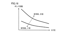
- FIG. 16 is a diagram schematically showing the relationship between the output flow rate of the pump of the conventional blood pressure monitor and the cuff pressure.
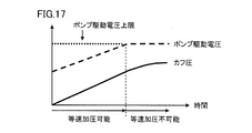
- FIG. 17 schematically shows the relationship between the conventional cuff pressure constant velocity pressurization and the pump drive voltage.
- miniaturization and cost reduction are required from the viewpoint of improving usability, and the pump is small to meet this demand.
- the pump size and the output flow rate of fluid such as air from the pump are in a trade-off relationship, a small pump cannot achieve a desired pressurization speed compared to a large pump. There is.
- the speed can be increased further. Therefore, the cuff pressure cannot be increased at a constant speed (see FIG. 17).
- the pressure fluctuation factor within one pulse wave includes not only the volume change component of the pulse wave but also the pressurization speed change component, so that the detection accuracy of the pulse wave amplitude is lowered. As a result, blood pressure calculation accuracy also decreases.
- an object of the present invention is to provide an electronic sphygmomanometer that can calculate blood pressure from a pulse wave that eliminates an error due to a change in the cuff pressure pressurization speed.
- An electronic sphygmomanometer adjusts the pressure in the cuff by controlling a cuff wound around the measurement site of the measurement subject and a pump for supplying fluid into the cuff.
- the control unit for controlling the adjustment unit so that the pressure in the cuff is pressurized at a constant speed according to the pressurization speed target during blood pressure measurement
- a target changing unit that variably changes the pressure speed target.
- the blood pressure calculation unit changes the pulse wave amplitude so as to correct an error of the pulse wave amplitude due to the change of the pressurization speed target, and calculates the blood pressure based on the cuff pressure and the changed pulse wave amplitude.
- the blood pressure is calculated from the pulse wave from which the error due to the change in the cuff pressure is changed.
- FIG. 3 is a block diagram illustrating a hardware configuration of the electronic blood pressure monitor according to Embodiment 1.
- FIG. 3 is a block diagram showing a functional configuration of the electronic blood pressure monitor according to Embodiment 1.
- FIG. It is a figure explaining the influence which pressurization speed has on a pulse wave amplitude, and amplitude correction of a pulse wave. It is a figure explaining the influence which pressurization speed has on a pulse wave amplitude, and amplitude correction of a pulse wave. It is a figure which shows a cuff compliance characteristic. It is a figure which shows the table which stores the correction coefficient which concerns on embodiment. It is a figure which shows typically correction
- FIG. 10 is a diagram for explaining the timing at which a pulse wave is detected in the pressurizing process according to the second embodiment.
- FIG. 10 is a processing flowchart of blood pressure measurement according to the second embodiment.
- FIG. 10 is a functional block diagram showing a functional configuration of an electronic blood pressure monitor according to Embodiment 2.
- FIG. 10 is a processing flowchart of blood pressure measurement according to the second embodiment.
- FIG. 10 is a functional block diagram showing a functional configuration of an electronic blood pressure monitor according to Embodiment 3.
- FIG. It is a figure which shows the table for determining the pressurization speed target which concerns on Embodiment 3.
- FIG. It is a figure which shows typically the relationship between the output flow volume of the pump of the conventional blood pressure meter, and a cuff pressure. It is a figure which shows typically the relationship between the constant velocity pressurization of the conventional cuff pressure, and a pump drive voltage.
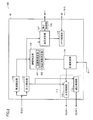
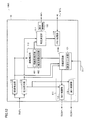
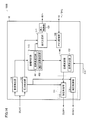
- FIG. 1 is a block diagram showing a hardware configuration of electronic blood pressure monitor 100 according to the present embodiment.
- an electronic sphygmomanometer 100 includes a cuff 20 and an air system 300 attached to a blood pressure measurement site.
- the cuff 20 includes an air bag 21.
- the air bag 21 is connected to the air system 300 via the air tube 31.
- the electronic sphygmomanometer 100 further centrally controls the display unit 40, the operation unit 41, and each unit to perform various arithmetic processes, a CPU (Central Processing Unit) 10, a program for causing the CPU 10 to perform predetermined operations, and various types It includes a memory unit 42 for storing data, a power source 44 for supplying power to each unit, and a clock unit 45 for performing a timing operation.
- the memory unit 42 includes a nonvolatile memory (for example, a flash memory) for storing the measured blood pressure.
- the operation unit 41 includes a power switch 41A that accepts an operation for turning the power on and off, a measurement switch 41B that accepts a measurement start operation, a stop switch 41C that accepts a measurement stop instruction operation, and a user (covered)
- a user selection switch 41E for accepting an operation for selectively designating (measurement person) is provided.
- the operation unit 41 also includes a switch (not shown) for receiving an operation for reading information such as measured blood pressure stored in the flash memory and displaying the information on the display unit.
- the electronic blood pressure monitor 100 since the electronic blood pressure monitor 100 is shared by a plurality of persons to be measured, the electronic blood pressure monitor 100 includes a user selection switch 41E. However, when not shared, the user selection switch 41E may be omitted.
- the measurement switch 41B may also be used as the power switch 41A. In that case, the measurement switch 41B can be omitted.
- the air system 300 includes a pressure sensor 32 for detecting the pressure in the air bladder 21 (hereinafter referred to as cuff pressure), a pump 51 for supplying air to the air bladder 21 to increase the cuff pressure, and air It includes a valve 52 that is opened and closed to evacuate or seal the bag 21 air.
- the electronic sphygmomanometer 100 includes an oscillation circuit 33, a pump drive circuit 53, and a valve drive circuit 54 in association with the air system 300.
- the pump 51, the valve 52, the pump drive circuit 53, and the valve drive circuit 54 correspond to the adjusting unit 30 for adjusting the cuff pressure.
- the pump 51 may be a pump using a motor as a drive source, a piezoelectric micro pump using a piezoelectric element as a drive source, or the like.
- the pressure sensor 32 is a capacitance type pressure sensor, and the capacitance value changes depending on the cuff pressure.
- the oscillation circuit 33 outputs an oscillation frequency signal (hereinafter referred to as a pressure signal) corresponding to the capacitance value of the pressure sensor 32 to the CPU 10.
- the CPU 10 detects the cuff pressure by converting the signal obtained from the oscillation circuit 33 into a pressure.
- the pump drive circuit 53 controls the pump 51 based on a control signal given from the CPU 10.
- the valve drive circuit 54 controls opening and closing of the valve 52 based on a control signal given from the CPU 10.
- the fluid supplied to the cuff 20 is not limited to air, and may be a liquid or a gel, for example. Or it is not limited to fluid, Uniform microparticles, such as a microbead, may be sufficient.
- FIG. 2 is a functional block diagram showing a functional configuration of electronic blood pressure monitor 100 according to the present embodiment.
- the functional configuration is indicated by using the functions of the CPU 10 and its peripheral part.
- the CPU 10 includes a pulse wave detection unit 118 and a pressure detection unit 112 for inputting a pressure signal from the oscillation circuit 33, an amplitude correction unit 113 for correcting the amplitude of the pulse wave, and an addition during blood pressure measurement.
- a target changing unit 114 that changes a pressure speed target (hereinafter referred to as a pressurization speed target), a pressurization control unit 115 that outputs control signals to the pump drive circuit 53 and the valve drive circuit 54, a depressurization control unit 116, and a blood pressure value.
- the pressurization control unit 115 and the decompression control unit 116 correspond to the drive control unit 111 for pressurizing the adjustment unit 30 during blood pressure measurement to pressurize the cuff pressure according to the pressurization speed target.
- the pressurization control unit 115 and the pressure reduction control unit 116 transmit control signals to the pump drive circuit 53 and the valve drive circuit 54 in order to adjust the cuff pressure. Specifically, a control signal for increasing or decreasing the cuff pressure is output.
- the blood pressure derivation process is performed by the blood pressure determination unit 117 in the process of increasing the cuff pressure with the pressurization speed target.
- the pulse wave detection unit 118 detects a pulse wave signal representing a change in the volume of the artery superimposed on the pressure signal from the oscillation circuit 33 using a filter circuit. In order to detect the cuff pressure, the pressure detection unit 112 converts the pressure signal from the oscillation circuit 33 into a pressure value and outputs the pressure value.
- the amplitude correction unit 113 includes a perimeter estimation unit 401 and a correction coefficient determination unit 402.
- the cuff 20 is wound around the measurement site, for example, the upper arm (or wrist).
- the perimeter estimation unit 401 estimates the length of the circumference (arm circumference) of the measurement site around which the cuff 20 is wound.
- the correction coefficient determination unit 402 determines a coefficient for correcting the pulse wave amplitude based on the pressurization speed target before and after the change.
- the blood pressure determining unit 117 determines the blood pressure according to the oscillometric equation. Specifically, the pulse cuff pressure input from the pressure detection unit 112 during blood pressure measurement and the pulse wave detected by the pulse wave detection unit 118 or the pulse wave whose amplitude is corrected by the amplitude correction unit 113 are used. The blood pressure is determined based on the wave amplitude transition and the cuff pressure. For example, the cuff pressure corresponding to the maximum value of the pulse wave amplitude is the average blood pressure, the cuff pressure corresponding to the pulse wave amplitude on the high cuff pressure side corresponding to 50% of the maximum value of the pulse wave amplitude is the systolic blood pressure, and the pulse wave.
- the cuff pressure corresponding to the pulse wave amplitude on the low cuff pressure side corresponding to 70% of the maximum value of the amplitude is determined as the diastolic blood pressure.
- the pulse rate is calculated according to a known procedure using the pulse wave signal. Therefore, here, the amplitude correction unit 113 and the blood pressure determination unit 117 correspond to a blood pressure calculation unit for calculating blood pressure.
- the cuff pressure When blood pressure is measured according to the oscillometric equation, the cuff pressure must be increased at a constant pressure target in order to obtain measurement accuracy. That is, the target changing unit 114 gives an initial value of the target speed to the pressurization control unit 115 at the start of blood pressure measurement.
- the pressurization control unit 115 calculates the cuff pressure change rate based on the cuff pressure periodically input from the pressure detection unit 112, and compares the calculated change rate with the pressurization rate target given from the target change unit 114. Then, a control signal based on the difference between the two based on the comparison result is generated and output to the pump drive circuit 53.
- the pump 51 is feedback-controlled so that the pressurization speed becomes the pressurization speed target.
- the discharge flow rate of the pump 51 is proportional to the voltage applied from the pump drive circuit 53.
- the pump drive circuit 53 outputs a voltage signal corresponding to the control signal to the pump 51.
- a voltage sensor (not shown) is provided at the output stage of the pump drive circuit 53, a voltage for driving the pump 51 is detected by the voltage sensor, and a drive voltage 511 indicating the detected voltage is output to the target changing unit 114.
- the target changing unit 114 compares the drive voltage 511 with the drive voltage upper limit 512 inherent to the pump 51, and based on the comparison result, the condition (drive voltage 511> drive voltage upper limit 512) is satisfied, and the output of the pump 51 is If it is determined that the maximum is not sufficient, the pressure speed target is changed to be lowered. Then, feedback control is performed using the changed pressurization speed target. Thereby, the pressurization speed can be controlled at a constant speed within a range where the output of the pump 51 has a margin.
- the pulse wave amplitude correction According to the oscillometric equation, the measurement accuracy of blood pressure depends on the pulse wave amplitude, but as described in FIGS. 16 and 17, the pulse wave amplitude includes the volume change component of the blood vessel within one pulse wave. In addition to the cuff pressure change rate component, it is necessary to correct the pulse wave amplitude error due to the latter component. Therefore, in the present embodiment, the pulse wave amplitude is corrected by eliminating the error caused by the change in the pressurization speed target described above.
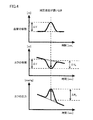
- 3 and 4 are data obtained by the inventors' experiments, and show the influence of the decompression speed in the decompression process on the pulse wave amplitude. Note that the principle shown in FIGS. 3 and 4 can be applied in the same way even in the pressurizing process.
- FIGS. 3 and 4 the time change of the cuff pressure is shown in the lower stage, the time change of the cuff volume is shown in the middle stage, and the arterial blood vessel of the measurement site is shown in the upper stage in the cases where the decompression speed is fast and slow.
- the time variation of the volume of is shown. These show changes in the same period.
- the maximum change in cuff volume with respect to the baseline (shown by a dotted line) of the cuff volume waveform is shown in the middle stage.
- the value varies depending on the decompression speed (that is, ⁇ Va ⁇ Vb).
- the pulse wave calculated by the thickness of the measurement site is obtained even when the blood vessel volume changes similarly. It can be seen that the amplitudes are different.
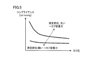
- the cuff compliance is a volume required to change the cuff pressure by 1 mmHg, and its unit is [ml / mmHg].
- the pulse wave amplitude detected when the pressurization speed of the cuff 20 is changed needs to be determined according to the rate of change of the pressurization speed and the circumference of the measurement site.
- the change rate of the pressurization speed is determined according to the change rate of the pressurization speed target.
- the rate of change refers to the ratio between the pressurization speed target before the change and the pressurization speed target after the change.
- the memory unit 42 stores a correction coefficient ⁇ corresponding to the peripheral length L of the measurement region and the post-change pressurization speed target V (here, the pre-change pressurization speed target is constant).
- Table TB is stored. Therefore, it can be said that the correction coefficient ⁇ is stored in the table TB corresponding to each set of the peripheral length L and the change rate of the pressurization speed target.
- the data in FIG. 6 is acquired through experiments or the like.
- the circumference length L of the measurement site is estimated by the circumference length estimation unit 401 based on the pressure change characteristic immediately after the start of pressurization.
- the correction coefficient determination unit 402 searches the table TB based on the peripheral length L and the post-change pressurization speed target V, and the corresponding correction coefficient. Read ⁇ . Thereby, the correction coefficient ⁇ is determined.
- the amplitude correction unit 113 extracts a pulse wave for each beat from the pulse wave signal (pressure signal) input from the pulse wave detection unit 118. Specifically, the difference between the current value of the pressure indicated by the pressure signal and the preceding value is calculated, it is determined whether the difference exceeds the reference, and the rising / falling point of the signal is extracted based on the determination result. Thereby, a pulse wave (one amplitude) can be extracted.
- the amplitude correction unit 113 corrects the amplitude value of the extracted pulse wave using the correction coefficient ⁇ . That is, the detected pulse wave amplitude value Amp is corrected by Amp ⁇ ⁇ .
- the corrected pulse wave is output to the blood pressure determination unit 117.
- the blood pressure determination unit 117 determines the blood pressure according to the oscillometric equation using the pulse wave whose amplitude is corrected.
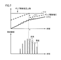
- FIG. 7 schematically shows pulse wave amplitude correction according to the present embodiment.
- the pressurization speed target for constant speed pressurization is changed in the range where the output of the pump 51 has a margin
- the error of the pulse wave amplitude due to the change is as described above. This can be eliminated by correcting the amplitude.
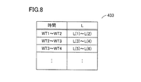
- FIG. 8 is a diagram showing an example of a table 433 that is referred to in order to estimate the measurement site circumference L according to the present embodiment.
- the table 433 stores the constant speed pressurization time required to pressurize the cuff pressure by a predetermined pressure when the winding state of the cuff 20 around the measurement site is “appropriate winding” and the corresponding peripheral length L. .
- the data in the table 433 is acquired in advance through experiments or the like.
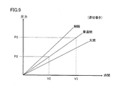
- FIG. 9 is a graph of cuff pressure-pressurization time characteristics (in the case of appropriate winding) according to the present embodiment.
- the pressurization time required for the pump 51 to supply the air of the fluid volume ⁇ V23 under constant pressure pressurization (constant rotation speed) in the pressurization process is a fixed time (here, time V23 from time V2 to time V3). It becomes. However, the time V23 varies depending on the peripheral length L of the measurement site.
- V23 increases.
- the peripheral length estimation unit 401 uses the clock unit 45 to measure the time required for the cuff pressure to change from 0 mmHg (pressure P2) to 20 mmHg (pressure P3) based on the detected cuff pressure after the start of pressurization. Then, the corresponding peripheral length L is acquired by searching the table 432 based on the measured time. The peripheral length L is given to the correction coefficient determination unit 402. The correction coefficient determination unit 402 searches the table TB based on the peripheral length L and the changed pressurization speed target V, and reads the corresponding correction coefficient ⁇ . Thereby, the correction coefficient ⁇ is determined.
- the peripheral length L is estimated (measured) at the time of blood pressure measurement, but the measured person may operate and input the operation unit 41 at the time of measurement. Alternatively, the peripheral length L may be stored in advance in the memory unit 42 for each person to be measured.
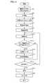
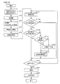
- FIG. 10 is a processing flowchart of blood pressure measurement according to the present embodiment.
- the program according to this flowchart is stored in advance in the memory unit 42, read from the memory unit 42 by the CPU 10, and executed.
- step ST1 When the measurement subject operates the power switch 41A (or the measurement switch 41B) with the cuff 20 wound around the measurement site in an appropriate manner (step ST1), the CPU 10 performs a predetermined initialization process, and then the CPU 10 Outputs a control signal for closing the valve 52 to the valve drive circuit 54. Thereby, the valve 52 is closed by the valve drive circuit 54 (step ST3).
- “SW” means a switch.
- the drive control unit 111 initially sets the pressurization speed target to a predetermined value (for example, 5.5 mmHg / sec), and outputs it to the pressurization control unit 115 (step ST5).
- the pressurization control unit 115 outputs a control signal to the pump drive circuit 53 so that the cuff pressure is pressurized at a constant speed according to the pressurization speed target (5.5 mmHg / sec).
- the pump drive circuit 53 outputs a drive signal (voltage signal) to the pump 51 so that the cuff pressure is pressurized at a constant pressurization speed target based on the control signal. Thereby, the cuff pressure is started at a constant pressure (step ST7).
- the perimeter estimation unit 401 estimates the perimeter L of the measurement site according to the procedure described above (step ST9). Even during the estimation period, the cuff pressure is maintained at a constant speed (step ST11).
- the constant speed pressurization is performed by feedback controlling the drive signal of the pump 51 as described above.
- the target changing unit 114 sequentially inputs the driving voltage 511 of the pump 51, and the voltage value of the driving voltage 511 and a predetermined voltage value stored in the memory unit 42 (for example, the driving voltage upper limit 512 of the pump 51). ) And based on the comparison result, it is determined whether or not the condition (value of drive voltage 511> predetermined voltage value) is satisfied (step ST13).
- step ST13 If it is determined that the condition is not satisfied (NO in step ST13), the process proceeds to step ST19.
- the blood pressure determination unit 117 determines the blood pressure according to the oscillometric formula based on the pulse wave amplitude input from the amplitude correction unit 113 and the cuff pressure detected by the pressure detection unit 112 in the constant pressure pressurization process. Since the blood pressure cannot be determined during a period when the pressure is not sufficiently increased (NO in step ST19), the process returns to step ST11, and the subsequent processes are repeated to proceed with constant velocity pressurization.
- the decompression control unit 116 stops the pump 51 and outputs a control signal for opening the valve 52. Thereby, the air in the air bladder 21 is exhausted and the cuff pressure is reduced (step ST21).
- the display control unit 120 displays the blood pressure and the pulse rate determined by the blood pressure determination unit 117 on the display unit 40 (step 40). ST23). The determined blood pressure and pulse rate are stored in the memory unit 42 together with the measurement time measured by the clock unit 45.
- step ST13 when the target changing unit 114 determines that the condition (value of drive voltage 511> predetermined voltage value (value of drive voltage upper limit 512)) is satisfied (YES in step ST13), that is, the pump 51 It is determined that the output capacity has reached the upper limit (see time T in FIG. 7).
- the target changing unit 114 determines that the above condition is satisfied, the target changing unit 114 changes the pressurization speed target to a predetermined value (for example, 3.0 mmHg / sec) (step ST15). Then, constant speed pressurization by feedback control is continued using the pressurization speed target after the change. Thus, constant speed pressurization control is performed in a range where the output of the pump 51 has a margin.
- the change of the pressurization speed target may be performed a plurality of times, or when the pressurization speed falls below the lower limit value, the measurement may be stopped and an error may be displayed.
- the correction coefficient determination unit 402 searches the table TB based on the post-change pressurization speed target and the surrounding length L estimated in step ST9, and the corresponding correction coefficient. Read ⁇ . Using the read correction coefficient ⁇ , the pulse wave amplitude is corrected, and the corrected pulse wave amplitude is output to the blood pressure determining unit 117 (step ST17). Thereby, the blood pressure determination unit 117 determines the blood pressure using the corrected pulse wave amplitude and the cuff pressure. Thereafter, similarly to the above, the processes after step ST19 are repeated.
- correction is performed by eliminating an error that occurs in the pulse wave amplitude due to a change in the constant speed pressurization speed due to the change in the pressurization speed target, and the blood pressure is corrected using the pulse wave amplitude after correction. Therefore, accurate blood pressure measurement can be performed.
- the timing for changing the pressurization speed target by resetting is determined based on the drive voltage 511 of the pump 51.
- pressurization is performed. It may be determined on the basis of the timing at which the pulse wave is detected after starting the operation.
- the pressurization speed is controlled at a constant speed within a range where the condition of (drive voltage 511 ⁇ drive voltage upper limit 512) is satisfied, that is, within a range where the output of the pump 51 has a margin.
- FIG. 11 is a diagram illustrating the timing at which a pulse wave is detected in the pressurizing process according to the second embodiment.
- 11A and 11B show a change in the driving voltage 511 over time in the pressurization process and a change in the cuff pressure on which the pulse wave is superimposed.
- the range of cuff pressure at which the pulse wave appears in the pressurizing process of constant velocity pressurization is low.
- blood pressure measurement can be completed without changing the pressure speed target.
- FIG. 12 is a functional block diagram showing a functional configuration of the electronic blood pressure monitor 100A according to the present embodiment.
- the functional configuration is indicated by using the functions of the CPU 10 and its peripheral part.
- the electronic blood pressure monitor 100A in FIG. 12 includes a target changing unit 114A in place of the target changing unit 114.
- the target changing unit 114A inputs the cuff pressure detected by the pressure detecting unit 112.
- the target changing unit 114A includes a pulse wave counting unit 121 that counts the number of pulse waves output from the pulse wave detecting unit 118, and changes the pressurization speed target based on the count value.
- FIG. 13 is a processing flowchart of blood pressure measurement according to the present embodiment.
- the program according to this flowchart is stored in advance in the memory unit 42, read from the memory unit 42 by the CPU 10, and executed.
- the blood pressure measurement process according to the present embodiment will be described with reference to the flowchart of FIG.
- steps ST1 to ST11 the same processing as in FIG. 10 is performed. Thereafter, the target changing unit 114A compares the cuff pressure detected by the pressure detecting unit 112 with a predetermined value (for example, 50 mmHg), and determines whether or not it is larger than the predetermined value based on the comparison result (step ST13a). If it is determined that the cuff pressure is equal to or lower than the predetermined value (NO in step ST13a), the process proceeds to step ST19. If it is determined that the cuff pressure is greater than the predetermined value (YES in step ST13a), blood pressure high / low screening is performed (step ST13b).
- a predetermined value for example, 50 mmHg
- the pulse wave counting unit 121 counts a pulse wave detected after starting pressurization, and the target changing unit 114A compares the count value with a predetermined value (for example, 2 beats), and compares It is determined whether it is larger than a predetermined value based on the result (step ST13b).
- a predetermined value for example, 2 beats
- Step ST13c Step ST15
- the pressurization speed target is reduced to a predetermined value (for example, 3.0 mmHg / sec) (step ST15), and constant pressure pressurization is executed using the post-change pressurization speed target.
- a predetermined value for example, 3.0 mmHg / sec
- the amplitude correction unit 113 corrects the pulse wave amplitude in the same manner as described above, and the blood pressure determination unit 117 performs processing for blood pressure determination using the corrected pulse wave amplitude. (Step ST17). Thereafter, processing similar to that described above (step ST19 to step ST23) is performed.
- step ST13a and step ST13b the pressurization speed target is changed while the count value of the pulse wave is determined to be equal to or less than the predetermined value during the period when the cuff pressure is less than the predetermined pressure (YES in step ST13a, YES in step ST13b).
- the constant speed pressurization proceeds without being performed.
- the measurement subject may input information indicating whether the blood pressure is high or low from the operation unit 41 in advance.
- the blood pressure measured in the past of the measurement subject may be read from the memory unit 42, compared with the reference blood pressure, and based on the result, it may be determined whether the blood pressure is high or low.
- the predetermined range of the cuff pressure to be counted is not limited to this range.
- the level of the blood pressure of the measurement subject is estimated based on the pulse wave number detected in a relatively early period from the start of pressurization, and the pressurization speed target is changed based on the result.
- the blood pressure can be determined without changing the pressure speed target, that is, without correcting the pulse wave amplitude.
- the pressure target after the change to be reset is a fixed value of a predetermined value (for example, 3.0 mmHg / sec).
- the length L may be changed variably. That is, since the capacity of the cuff 20 increases as the peripheral length L of the measurement site increases, the pump 51 is required to have a high output (a large discharge amount). Therefore, in order to pressurize at a constant speed with a limited discharge amount, it is desirable to determine the pressurization speed target based on the peripheral length L.
- the pressurization speed is controlled at a constant speed as long as the condition (driving voltage 511 ⁇ driving voltage upper limit 512) is satisfied, that is, the output of the pump 51 has a margin.
- FIG. 14 is a functional block diagram showing a functional configuration of the electronic sphygmomanometer 100B according to the third embodiment.
- the functional configuration is indicated by using the functions of the CPU 10 and its peripheral part.
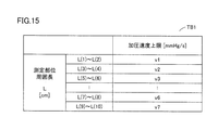
- FIG. 15 is a diagram showing a table TB1 for determining a pressurization speed target according to the present embodiment.
- electronic blood pressure monitor 100 ⁇ / b> B includes target changing unit 114 ⁇ / b> B instead of target changing unit 114.
- the target changing unit 114B inputs the peripheral length L estimated by the peripheral length estimation unit 401, searches the table TB1 of FIG. 15 based on the peripheral length L, and determines the pressure target after the change.
- the table TB1 is stored in the memory unit 42 in advance.
- the target determining unit 122 searches the table TB1 based on the estimated peripheral length L and reads the corresponding pressurization speed v.
- the target changing unit 114B determines the read pressurization speed v as the post-change pressurization speed target.
- the target determining unit 122 may be included in the target changing unit 114A of the electronic sphygmomanometer 100A of FIG.
- the pressurization speed target can be set according to the peripheral length L of the measurement site, and constant pressure can be applied.
- 20 cuff, 51 pump, 52 valve, 53 pump drive circuit, 54 valve drive circuit, 100, 100A, 100B electronic sphygmomanometer, 111 drive control unit, 112 pressure detection unit, 113 amplitude correction unit, 114, 114A, 114B target change 115, pressurization control unit, 116 decompression control unit, 117 blood pressure determination unit, 118 pulse wave detection unit, 119 memory processing unit, 120 display control unit, 121 pulse wave count unit, 122 target determination unit, 401 circumference length estimation unit 402, correction coefficient determination unit, 432, 433, TB1 table, 511 drive voltage, 512 drive voltage upper limit.
Abstract
A blood pressure meter (100) is provided with: a cuff to be disposed around the periphery of the part of a person at which blood pressure is to be measured; an adjustment unit for adjusting pressure within the cuff by controlling a pump for supplying fluid into the cuff; a control unit for controlling the adjustment unit so that, during the measurement of blood pressure, the pressure within the cuff is increased at a constant speed according to a target pressurization speed; a pressure detection unit for detecting a cuff pressure representing the pressure within the cuff; a pulse wave detection unit (118) for detecting a pulse wave superposed on the cuff pressure; a blood pressure calculation unit for calculating blood pressure on the basis of the detected cuff pressure and of a pulse wave amplitude; and a target change unit (114) for changing in a variable manner the target pressurization speed. The blood pressure calculation unit changes the pulse wave amplitude so as to correct an error in the pulse wave amplitude caused by a change in the target pressurization speed and calculates blood pressure on the basis of the cuff pressure and the changed pulse wave amplitude.
Description
本発明は電子血圧計に関し、特に、測定部位から検出される脈波を用いて血圧を測定する電子血圧計に関する。
The present invention relates to an electronic sphygmomanometer, and more particularly to an electronic sphygmomanometer that measures blood pressure using a pulse wave detected from a measurement site.
血圧は循環器系疾患を解析する指標の一つであり、血圧に基づいてリスク解析を行うことは、例えば脳卒中や心不全や心筋梗塞などの心血管系の疾患の予防に有効である。従来は通院時や健康診断時などの医療機関で測定される血圧(随時血圧)により診断が行われていた。しかしながら近年の研究により、家庭で測定する血圧(家庭血圧)が随時血圧より循環器系疾患の診断に有用であることが判明してきた。それに伴い、家庭で使用する血圧計が普及している。
Blood pressure is one of the indices for analyzing circulatory diseases, and risk analysis based on blood pressure is effective in preventing cardiovascular diseases such as stroke, heart failure and myocardial infarction. Conventionally, diagnosis has been performed based on blood pressure (anytime blood pressure) measured at a medical institution such as when visiting a hospital or during a medical examination. However, recent studies have shown that blood pressure measured at home (home blood pressure) is more useful for diagnosis of cardiovascular diseases than blood pressure at any time. Accordingly, blood pressure monitors used at home have become widespread.
家庭向けの血圧計の多くがオシロメトリック法による血圧測定方法を採用している。オシロメトリック法による血圧測定は、カフを上腕などの測定部位に巻付け、カフの内圧(カフ圧)を収縮期血圧より所定圧(例えば30mmHg)だけ高く加圧し、その後、徐々にまたは段階的にカフ圧を減圧していく。この減圧過程における動脈の容積変化をカフ圧に重畳した圧変化(脈波振幅)として検出し、この脈波振幅の変化より収縮期血圧および拡張期血圧を決定する方法である。オシロメトリック法では、カフ圧の加圧過程において発生する脈波振幅を検出して血圧を測定することも可能である。
Most home blood pressure monitors use the oscillometric blood pressure measurement method. Blood pressure measurement by the oscillometric method is to wrap the cuff around a measurement site such as the upper arm, pressurize the cuff internal pressure (cuff pressure) by a predetermined pressure (for example, 30 mmHg) higher than the systolic blood pressure, and then gradually or stepwise. Reduce the cuff pressure. In this decompression process, the volume change of the artery is detected as a pressure change (pulse wave amplitude) superimposed on the cuff pressure, and the systolic blood pressure and the diastolic blood pressure are determined from the change in the pulse wave amplitude. In the oscillometric method, the blood pressure can be measured by detecting the amplitude of the pulse wave generated in the process of increasing the cuff pressure.
これらの血圧測定において正確に脈波振幅を検出するためには、ポンプまたは弁によりカフ圧を一定速度で、加圧または減圧する必要がある。そこで、特許文献1(特開2006-129920号公報)では、等速加圧制御、または等速減圧制御では平均速度と目標速度との差に基づいて、平均速度が目標速度となるようにポンプまたは弁の駆動電圧をフィードバック制御する。
In order to accurately detect the pulse wave amplitude in these blood pressure measurements, it is necessary to increase or decrease the cuff pressure at a constant speed by a pump or a valve. Therefore, in Patent Document 1 (Japanese Patent Application Laid-Open No. 2006-129920), the constant speed pressurization control or the constant speed depressurization control is based on the difference between the average speed and the target speed so that the average speed becomes the target speed. Alternatively, the valve drive voltage is feedback controlled.
図16は、従来の血圧計のポンプの出力流量と、カフ圧の関係を模式的に示す図である。図17には、従来のカフ圧の等速加圧とポンプ駆動電圧の関係が模式的に示される。家庭用の血圧計においては、ユーザビリティ向上の観点から小型化や低コスト化が求められており、それに応えるためにポンプは小型である。図16に示されるように、ポンプのサイズとポンプからの空気などの流体の出力流量はトレードオフの関係にあるため、大型のポンプに比較し小型のポンプは所望の加圧速度を達成できない場合がある。
FIG. 16 is a diagram schematically showing the relationship between the output flow rate of the pump of the conventional blood pressure monitor and the cuff pressure. FIG. 17 schematically shows the relationship between the conventional cuff pressure constant velocity pressurization and the pump drive voltage. In home sphygmomanometers, miniaturization and cost reduction are required from the viewpoint of improving usability, and the pump is small to meet this demand. As shown in FIG. 16, since the pump size and the output flow rate of fluid such as air from the pump are in a trade-off relationship, a small pump cannot achieve a desired pressurization speed compared to a large pump. There is.
また、小型のポンプの場合には、加圧速度を目標速度に一致させるようにフィードバック制御される駆動電圧がポンプ駆動の上限電圧を超えてしまった場合、それ以上に速度を増加させることができず、カフ圧を等速で加圧することができない(図17参照)。この場合は脈波1拍内での圧力変動要因として、脈波の容積変化成分のみならず、加圧速度変化成分も含まれるため、脈波振幅の検出精度が低下する。そのため血圧算出精度も低下してしまう。
In the case of a small pump, if the drive voltage that is feedback controlled so that the pressurization speed matches the target speed exceeds the upper limit voltage of the pump drive, the speed can be increased further. Therefore, the cuff pressure cannot be increased at a constant speed (see FIG. 17). In this case, the pressure fluctuation factor within one pulse wave includes not only the volume change component of the pulse wave but also the pressurization speed change component, so that the detection accuracy of the pulse wave amplitude is lowered. As a result, blood pressure calculation accuracy also decreases.
それゆえに、本発明の目的は、カフ圧の加圧速度の変化による誤差を排除した脈波から血圧を算出することのできる電子血圧計を提供することである。
Therefore, an object of the present invention is to provide an electronic sphygmomanometer that can calculate blood pressure from a pulse wave that eliminates an error due to a change in the cuff pressure pressurization speed.
この発明のある局面に従う電子血圧計は、被測定者の測定部位の周囲に巻付けられるカフと、カフ内に流体を供給するためのポンプを制御することにより、前記カフ内の圧力を調整するための調整部と、血圧測定中に、加圧速度目標に従ってカフ内の圧力が等速加圧されるように調整部を制御する制御部と、カフ内の圧力を表わすカフ圧を検出するための圧力検出部と、カフ圧に重畳する脈波を検出するための脈波検出部と、検出されるカフ圧と、脈波振幅とに基づいて血圧を算出するための血圧算出部と、加圧速度目標を可変に変更する目標変更部と、を備える。血圧算出部は、加圧速度目標の変更による脈波振幅の誤差を補正するように脈波振幅を変更し、カフ圧と変更後の脈波振幅とに基づいて血圧を算出する。
An electronic sphygmomanometer according to an aspect of the present invention adjusts the pressure in the cuff by controlling a cuff wound around the measurement site of the measurement subject and a pump for supplying fluid into the cuff. For detecting the cuff pressure representing the pressure in the cuff, the control unit for controlling the adjustment unit so that the pressure in the cuff is pressurized at a constant speed according to the pressurization speed target during blood pressure measurement A pressure detector, a pulse wave detector for detecting a pulse wave superimposed on the cuff pressure, a blood pressure calculator for calculating blood pressure based on the detected cuff pressure and the pulse wave amplitude, A target changing unit that variably changes the pressure speed target. The blood pressure calculation unit changes the pulse wave amplitude so as to correct an error of the pulse wave amplitude due to the change of the pressurization speed target, and calculates the blood pressure based on the cuff pressure and the changed pulse wave amplitude.
本発明によれば、カフ圧の加圧速度の変化による誤差を排除した脈波から血圧を算出する。
According to the present invention, the blood pressure is calculated from the pulse wave from which the error due to the change in the cuff pressure is changed.
以下、図面を参照しつつ、本発明の各実施の形態について説明する。以下の説明では、同一の部品には同一の符号を付してある。それらの名称および機能も同じである。したがって、それらについての詳細な説明は繰り返さない。
Hereinafter, embodiments of the present invention will be described with reference to the drawings. In the following description, the same parts are denoted by the same reference numerals. Their names and functions are also the same. Therefore, detailed description thereof will not be repeated.
(実施の形態1)
図1は、本実施の形態に係る電子血圧計100のハードウェア構成を表わすブロック図である。図1を参照して、電子血圧計100は血圧測定部位に装着されるカフ20およびエア系300を備える。カフ20は空気袋21を含む。空気袋21は、エアチューブ31を介して、エア系300に接続される。 (Embodiment 1)
FIG. 1 is a block diagram showing a hardware configuration of electronicblood pressure monitor 100 according to the present embodiment. Referring to FIG. 1, an electronic sphygmomanometer 100 includes a cuff 20 and an air system 300 attached to a blood pressure measurement site. The cuff 20 includes an air bag 21. The air bag 21 is connected to the air system 300 via the air tube 31.
図1は、本実施の形態に係る電子血圧計100のハードウェア構成を表わすブロック図である。図1を参照して、電子血圧計100は血圧測定部位に装着されるカフ20およびエア系300を備える。カフ20は空気袋21を含む。空気袋21は、エアチューブ31を介して、エア系300に接続される。 (Embodiment 1)
FIG. 1 is a block diagram showing a hardware configuration of electronic
電子血圧計100は、さらに表示部40、操作部41および各部を集中的に制御し、各種演算処理を行なうためのCPU(Central Processing Unit)10、CPU10に所定の動作をさせるためのプログラムや各種データを記憶するためのメモリ部42、各部に電力を供給するための電源44、計時動作を行なうための時計部45を含む。メモリ部42は、測定された血圧を記憶するための不揮発性メモリ(例えばフラッシュメモリ)などを含む。
The electronic sphygmomanometer 100 further centrally controls the display unit 40, the operation unit 41, and each unit to perform various arithmetic processes, a CPU (Central Processing Unit) 10, a program for causing the CPU 10 to perform predetermined operations, and various types It includes a memory unit 42 for storing data, a power source 44 for supplying power to each unit, and a clock unit 45 for performing a timing operation. The memory unit 42 includes a nonvolatile memory (for example, a flash memory) for storing the measured blood pressure.
操作部41は、電源をONまたはOFFするための操作を受付ける電源スイッチ41A、測定開始の操作を受付けるための測定スイッチ41B、測定停止の指示の操作を受付けるための停止スイッチ41C、およびユーザ(被測定者)を選択的に指定する操作を受付けるための使用者選択スイッチ41Eを有する。操作部41は、フラッシュメモリに格納された測定血圧などの情報を読出し表示部に表示させる操作を受付けるための図示のないスイッチも有する。
The operation unit 41 includes a power switch 41A that accepts an operation for turning the power on and off, a measurement switch 41B that accepts a measurement start operation, a stop switch 41C that accepts a measurement stop instruction operation, and a user (covered) A user selection switch 41E for accepting an operation for selectively designating (measurement person) is provided. The operation unit 41 also includes a switch (not shown) for receiving an operation for reading information such as measured blood pressure stored in the flash memory and displaying the information on the display unit.
本実施の形態では、電子血圧計100は複数の被測定者により共用されることから、使用者選択スイッチ41Eを備えるが、共用されない場合には使用者選択スイッチ41Eは省略されてよい。また、測定スイッチ41Bを、電源スイッチ41Aと兼用してもよい。その場合には、測定スイッチ41Bは省略することができる。
In the present embodiment, since the electronic blood pressure monitor 100 is shared by a plurality of persons to be measured, the electronic blood pressure monitor 100 includes a user selection switch 41E. However, when not shared, the user selection switch 41E may be omitted. The measurement switch 41B may also be used as the power switch 41A. In that case, the measurement switch 41B can be omitted.
エア系300は、空気袋21内の圧力(以下、カフ圧という)を検出するための圧力センサ32、カフ圧を加圧するために、空気袋21に空気を供給するためのポンプ51、および空気袋21の空気を排出しまたは封入するために開閉される弁52を含む。電子血圧計100は、エア系300に関連して、発振回路33、ポンプ駆動回路53、および弁駆動回路54を含む。ここでは、ポンプ51、弁52、ポンプ駆動回路53および弁駆動回路54は、カフ圧を調整するための調整部30に相当する。
The air system 300 includes a pressure sensor 32 for detecting the pressure in the air bladder 21 (hereinafter referred to as cuff pressure), a pump 51 for supplying air to the air bladder 21 to increase the cuff pressure, and air It includes a valve 52 that is opened and closed to evacuate or seal the bag 21 air. The electronic sphygmomanometer 100 includes an oscillation circuit 33, a pump drive circuit 53, and a valve drive circuit 54 in association with the air system 300. Here, the pump 51, the valve 52, the pump drive circuit 53, and the valve drive circuit 54 correspond to the adjusting unit 30 for adjusting the cuff pressure.
ポンプ51には、モータを駆動源として用いるポンプ、圧電素子を駆動源として用いた圧電マイクロポンプなどを適用することができる。
The pump 51 may be a pump using a motor as a drive source, a piezoelectric micro pump using a piezoelectric element as a drive source, or the like.
圧力センサ32は、静電容量形の圧力センサであり、カフ圧により容量値が変化する。発振回路33は、圧力センサ32の容量値に応じた発振周波数の信号(以下、圧力信号という)をCPU10に出力する。CPU10は、発振回路33から得られる信号を圧力に変換することによってカフ圧を検知する。ポンプ駆動回路53は、CPU10から与えられる制御信号に基づいてポンプ51を制御する。弁駆動回路54はCPU10から与えられる制御信号に基づいて弁52の開閉を制御する。
The pressure sensor 32 is a capacitance type pressure sensor, and the capacitance value changes depending on the cuff pressure. The oscillation circuit 33 outputs an oscillation frequency signal (hereinafter referred to as a pressure signal) corresponding to the capacitance value of the pressure sensor 32 to the CPU 10. The CPU 10 detects the cuff pressure by converting the signal obtained from the oscillation circuit 33 into a pressure. The pump drive circuit 53 controls the pump 51 based on a control signal given from the CPU 10. The valve drive circuit 54 controls opening and closing of the valve 52 based on a control signal given from the CPU 10.
なお、カフ20に供給される流体は空気に限定されるものではなく、例えば液体やゲルであってもよい。あるいは、流体に限定されるものではなく、マイクロビーズなどの均一な微粒子であってもよい。
In addition, the fluid supplied to the cuff 20 is not limited to air, and may be a liquid or a gel, for example. Or it is not limited to fluid, Uniform microparticles, such as a microbead, may be sufficient.
(機能構成)
図2は、本実施の形態に係る電子血圧計100の機能構成を示す機能ブロック図である。機能構成は、CPU10が有する機能と、その周辺部を用いて示される。 (Functional configuration)
FIG. 2 is a functional block diagram showing a functional configuration of electronic blood pressure monitor 100 according to the present embodiment. The functional configuration is indicated by using the functions of theCPU 10 and its peripheral part.
図2は、本実施の形態に係る電子血圧計100の機能構成を示す機能ブロック図である。機能構成は、CPU10が有する機能と、その周辺部を用いて示される。 (Functional configuration)
FIG. 2 is a functional block diagram showing a functional configuration of electronic blood pressure monitor 100 according to the present embodiment. The functional configuration is indicated by using the functions of the
図2を参照して、CPU10は、発振回路33からの圧力信号を入力する脈波検出部118および圧力検出部112、脈波の振幅を補正するための振幅補正部113、血圧測定に際しての加圧速度の目標(以下、加圧速度目標という)を変更する目標変更部114、ポンプ駆動回路53と弁駆動回路54とに制御信号を出力する加圧制御部115および減圧制御部116、血圧値を決定する血圧決定部117、メモリ部42のフラッシュメモリのデータを読み書き(アクセス)するためのメモリ処理部119、および表示部40の表示を制御する表示制御部120を備える。加圧制御部115と減圧制御部116は、血圧測定中に調整部30を駆動制御することにより、加圧速度目標に従ってカフ圧を加圧させるための駆動制御部111に相当する。
Referring to FIG. 2, the CPU 10 includes a pulse wave detection unit 118 and a pressure detection unit 112 for inputting a pressure signal from the oscillation circuit 33, an amplitude correction unit 113 for correcting the amplitude of the pulse wave, and an addition during blood pressure measurement. A target changing unit 114 that changes a pressure speed target (hereinafter referred to as a pressurization speed target), a pressurization control unit 115 that outputs control signals to the pump drive circuit 53 and the valve drive circuit 54, a depressurization control unit 116, and a blood pressure value. Is provided with a blood pressure determination unit 117 for determining the data, a memory processing unit 119 for reading and writing (accessing) data in the flash memory of the memory unit 42, and a display control unit 120 for controlling display on the display unit 40. The pressurization control unit 115 and the decompression control unit 116 correspond to the drive control unit 111 for pressurizing the adjustment unit 30 during blood pressure measurement to pressurize the cuff pressure according to the pressurization speed target.
加圧制御部115および減圧制御部116は、カフ圧を調整するために、ポンプ駆動回路53および弁駆動回路54に制御信号を送信する。具体的には、カフ圧を加圧し、または減圧するための制御信号を出力する。本実施の形態では、カフ圧を加圧速度目標で加圧する過程において、血圧決定部117による血圧導出処理が行なわれる。脈波検出部118は、発振回路33からの圧力信号に重畳される動脈の容積変化を表す脈波信号を、フィルタ回路を用いて検出する。圧力検出部112は、カフ圧を検出するために、発振回路33からの圧力信号を圧力値に変換し、出力する。
The pressurization control unit 115 and the pressure reduction control unit 116 transmit control signals to the pump drive circuit 53 and the valve drive circuit 54 in order to adjust the cuff pressure. Specifically, a control signal for increasing or decreasing the cuff pressure is output. In the present embodiment, the blood pressure derivation process is performed by the blood pressure determination unit 117 in the process of increasing the cuff pressure with the pressurization speed target. The pulse wave detection unit 118 detects a pulse wave signal representing a change in the volume of the artery superimposed on the pressure signal from the oscillation circuit 33 using a filter circuit. In order to detect the cuff pressure, the pressure detection unit 112 converts the pressure signal from the oscillation circuit 33 into a pressure value and outputs the pressure value.
振幅補正部113は、周囲長推定部401および補正係数決定部402を含む。カフ20は、測定部位である例えば上腕(または手首)に巻き付けられる。周囲長推定部401は、カフ20が巻き付けられた測定部位の周囲(腕周)の長さを推定する。補正係数決定部402は、変更前後の加圧速度目標に基づき、脈波振幅を補正するための係数を決定する。
The amplitude correction unit 113 includes a perimeter estimation unit 401 and a correction coefficient determination unit 402. The cuff 20 is wound around the measurement site, for example, the upper arm (or wrist). The perimeter estimation unit 401 estimates the length of the circumference (arm circumference) of the measurement site around which the cuff 20 is wound. The correction coefficient determination unit 402 determines a coefficient for correcting the pulse wave amplitude based on the pressurization speed target before and after the change.
血圧決定部117は、オシロメトリック式に従い血圧を決定する。具体的には、血圧測定時に圧力検出部112から入力するカフ圧と、脈波検出部118により検出された脈波、または振幅補正部113により振幅が補正された脈波とを用いて、脈波振幅の推移とカフ圧とに基づき血圧を決定する。例えば、脈波振幅の最大値に対応するカフ圧を平均血圧、また脈波振幅の最大値の50%に相当する高カフ圧側の脈波振幅に対応するカフ圧を収縮期血圧、また脈波振幅の最大値の70%に相当する低カフ圧側の脈波振幅に対応するカフ圧を拡張期血圧と決定する。また、脈拍数を、脈波信号を用いて公知の手順に従って算出する。したがって、ここでは、振幅補正部113および血圧決定部117は、血圧を算出するための血圧算出部に相当する。
The blood pressure determining unit 117 determines the blood pressure according to the oscillometric equation. Specifically, the pulse cuff pressure input from the pressure detection unit 112 during blood pressure measurement and the pulse wave detected by the pulse wave detection unit 118 or the pulse wave whose amplitude is corrected by the amplitude correction unit 113 are used. The blood pressure is determined based on the wave amplitude transition and the cuff pressure. For example, the cuff pressure corresponding to the maximum value of the pulse wave amplitude is the average blood pressure, the cuff pressure corresponding to the pulse wave amplitude on the high cuff pressure side corresponding to 50% of the maximum value of the pulse wave amplitude is the systolic blood pressure, and the pulse wave. The cuff pressure corresponding to the pulse wave amplitude on the low cuff pressure side corresponding to 70% of the maximum value of the amplitude is determined as the diastolic blood pressure. The pulse rate is calculated according to a known procedure using the pulse wave signal. Therefore, here, the amplitude correction unit 113 and the blood pressure determination unit 117 correspond to a blood pressure calculation unit for calculating blood pressure.
(ポンプ51のフィードバック制御)
オシロメトリック式に従って血圧測定する場合には、測定精度を得るために、カフ圧を一定の加圧速度目標で加圧しなければならない。つまり、目標変更部114は、血圧測定開始時に加圧制御部115に対して目標速度の初期値を与える。加圧制御部115は、圧力検出部112から定期的に入力するカフ圧に基づきカフ圧の変化速度を算出し、算出した変化速度と、目標変更部114から与えられる加圧速度目標と比較し、比較結果に基づく両者の差に基づく制御信号を生成し、ポンプ駆動回路53に出力する。このように、加圧速度が、加圧速度目標となるようにポンプ51はフィードバック制御される。 (Feedback control of pump 51)
When blood pressure is measured according to the oscillometric equation, the cuff pressure must be increased at a constant pressure target in order to obtain measurement accuracy. That is, thetarget changing unit 114 gives an initial value of the target speed to the pressurization control unit 115 at the start of blood pressure measurement. The pressurization control unit 115 calculates the cuff pressure change rate based on the cuff pressure periodically input from the pressure detection unit 112, and compares the calculated change rate with the pressurization rate target given from the target change unit 114. Then, a control signal based on the difference between the two based on the comparison result is generated and output to the pump drive circuit 53. Thus, the pump 51 is feedback-controlled so that the pressurization speed becomes the pressurization speed target.
オシロメトリック式に従って血圧測定する場合には、測定精度を得るために、カフ圧を一定の加圧速度目標で加圧しなければならない。つまり、目標変更部114は、血圧測定開始時に加圧制御部115に対して目標速度の初期値を与える。加圧制御部115は、圧力検出部112から定期的に入力するカフ圧に基づきカフ圧の変化速度を算出し、算出した変化速度と、目標変更部114から与えられる加圧速度目標と比較し、比較結果に基づく両者の差に基づく制御信号を生成し、ポンプ駆動回路53に出力する。このように、加圧速度が、加圧速度目標となるようにポンプ51はフィードバック制御される。 (Feedback control of pump 51)
When blood pressure is measured according to the oscillometric equation, the cuff pressure must be increased at a constant pressure target in order to obtain measurement accuracy. That is, the
ここでは、ポンプ51の吐出流量がポンプ駆動回路53から与えられる電圧に比例すると想定する。ポンプ駆動回路53は、制御信号に応じた電圧信号をポンプ51に出力する。ポンプ駆動回路53の出力段には図示のない電圧センサが設けられて、当該電圧センサによりポンプ51を駆動するための電圧が検出され、検出電圧を示す駆動電圧511が目標変更部114に出力される。
Here, it is assumed that the discharge flow rate of the pump 51 is proportional to the voltage applied from the pump drive circuit 53. The pump drive circuit 53 outputs a voltage signal corresponding to the control signal to the pump 51. A voltage sensor (not shown) is provided at the output stage of the pump drive circuit 53, a voltage for driving the pump 51 is detected by the voltage sensor, and a drive voltage 511 indicating the detected voltage is output to the target changing unit 114. The
目標変更部114は、駆動電圧511と、ポンプ51に固有の駆動電圧上限512とを比較し、比較結果に基づき、(駆動電圧511>駆動電圧上限512)の条件が成立しポンプ51の出力は最大であり余裕がないと判定すると、加圧速度目標を下げるように変更する。そして、変更後の加圧速度目標を用いてフィードバック制御が行われる。これにより、ポンプ51の出力に余裕のある範囲で加圧速度を等速に制御できる。
The target changing unit 114 compares the drive voltage 511 with the drive voltage upper limit 512 inherent to the pump 51, and based on the comparison result, the condition (drive voltage 511> drive voltage upper limit 512) is satisfied, and the output of the pump 51 is If it is determined that the maximum is not sufficient, the pressure speed target is changed to be lowered. Then, feedback control is performed using the changed pressurization speed target. Thereby, the pressurization speed can be controlled at a constant speed within a range where the output of the pump 51 has a margin.
(脈波振幅の補正)
オシロメトリック式によれば、血圧の測定精度は、脈波振幅に依存するが、図16と図17で説明したように、脈波振幅には、脈波1拍内での血管の容積変化成分のみならずカフ圧の変化速度の成分も含むから、後者の成分に起因した脈波振幅の誤差を排除するように補正する必要がある。そこで、本実施の形態では、上述した加圧速度目標の変更に起因した誤差を排除することにより、脈波振幅を補正する。 (Pulse wave amplitude correction)
According to the oscillometric equation, the measurement accuracy of blood pressure depends on the pulse wave amplitude, but as described in FIGS. 16 and 17, the pulse wave amplitude includes the volume change component of the blood vessel within one pulse wave. In addition to the cuff pressure change rate component, it is necessary to correct the pulse wave amplitude error due to the latter component. Therefore, in the present embodiment, the pulse wave amplitude is corrected by eliminating the error caused by the change in the pressurization speed target described above.
ここで、図3と4を参照して、加圧速度が脈波振幅に与える影響と、振幅補正について説明する。図3と4は発明者らの実験によるデータであり、減圧過程における減圧速度が脈波振幅に与える影響を示す。なお、図3と図4で示す原理は、加圧過程であっても同様に適用することができる。
Here, with reference to FIGS. 3 and 4, the influence of the pressurization speed on the pulse wave amplitude and the amplitude correction will be described. 3 and 4 are data obtained by the inventors' experiments, and show the influence of the decompression speed in the decompression process on the pulse wave amplitude. Note that the principle shown in FIGS. 3 and 4 can be applied in the same way even in the pressurizing process.
図3と図4では、減圧速度が速い場合と遅い場合とで、下段にはカフ圧の時間変化が示され、中段にはカフ容積の時間変化が示され、上段には測定部位の動脈血管の容積の時間変化が示される。これらは同一期間における変化を示す。図3と図4では、上段のように心臓の拍動による血管の容積変化ΔVが等しい場合であっても、中段に示すようにカフ容積波形の基線(点線で図示)に対するカフ容積変化の最大値は減圧速度によって相違する(すなわち、ΔVa<ΔVb)。この容積変化はカフ圧変化として表われるため、減圧速度が遅いほどカフ20の容積変化が大きくなり、下段のようにカフ圧変化も相違する(すなわち、ΔPa<ΔPb)。したがって、同様に血管容積が変化する場合であっても、減圧速度または加圧速度によって検出される脈波振幅は相違することになる。
In FIGS. 3 and 4, the time change of the cuff pressure is shown in the lower stage, the time change of the cuff volume is shown in the middle stage, and the arterial blood vessel of the measurement site is shown in the upper stage in the cases where the decompression speed is fast and slow. The time variation of the volume of is shown. These show changes in the same period. In FIGS. 3 and 4, even if the blood vessel volume change ΔV due to the pulsation of the heart is equal as in the upper stage, the maximum change in cuff volume with respect to the baseline (shown by a dotted line) of the cuff volume waveform is shown in the middle stage. The value varies depending on the decompression speed (that is, ΔVa <ΔVb). Since this volume change appears as a cuff pressure change, the volume change of the cuff 20 increases as the depressurization speed decreases, and the cuff pressure change also differs as in the lower stage (ie, ΔPa <ΔPb). Therefore, even if the blood vessel volume changes in the same manner, the pulse wave amplitude detected by the pressure reduction rate or the pressure increase rate is different.
また、図5に示すカフコンプライアンス特性から、測定部位が太い(周囲長が長い)ほどカフコンプライアンスが大きくなるため、同様の血管容積変化であっても、測定部位の太さにより算出される脈波振幅が異なる、ことがわかる。なお、ここでいうカフコンプライアンスとはカフ圧を1mmHg変化させるのに必要な容積であり、単位は[ml/mmHg]である。
Further, from the cuff compliance characteristics shown in FIG. 5, since the cuff compliance becomes larger as the measurement site is thicker (periphery length is longer), the pulse wave calculated by the thickness of the measurement site is obtained even when the blood vessel volume changes similarly. It can be seen that the amplitudes are different. Here, the cuff compliance is a volume required to change the cuff pressure by 1 mmHg, and its unit is [ml / mmHg].
したがって、カフ20の加圧速度を変化させた場合に検出される脈波振幅は、加圧速度の変化率と測定部位の周囲長に応じて決定する必要がある。ここで、加圧速度の変化率は、加圧速度目標の変化率に応じて決まる。ここで、変化率は、変更前の加圧速度目標と変更後の加圧速度目標との比を指す。
Therefore, the pulse wave amplitude detected when the pressurization speed of the cuff 20 is changed needs to be determined according to the rate of change of the pressurization speed and the circumference of the measurement site. Here, the change rate of the pressurization speed is determined according to the change rate of the pressurization speed target. Here, the rate of change refers to the ratio between the pressurization speed target before the change and the pressurization speed target after the change.
メモリ部42には、測定部位の周囲長Lと、変更後の加圧速度目標V(ここでは、変更前の加圧速度目標は一定としている)とに応じた補正係数αを格納した図6のテーブルTBが格納される。したがって、テーブルTBには、周囲長Lと加圧速度目標の変化率の各組に対応して補正係数αが格納されると言える。図6のデータは、実験等により取得される。
The memory unit 42 stores a correction coefficient α corresponding to the peripheral length L of the measurement region and the post-change pressurization speed target V (here, the pre-change pressurization speed target is constant). Table TB is stored. Therefore, it can be said that the correction coefficient α is stored in the table TB corresponding to each set of the peripheral length L and the change rate of the pressurization speed target. The data in FIG. 6 is acquired through experiments or the like.
血圧測定時には、加圧開始直後の圧力変化特性に基づき周囲長推定部401により測定部位の周囲長Lを推定する。そして、目標変更部114によって加圧速度目標が変更された後は、補正係数決定部402は周囲長Lと変更後の加圧速度目標Vとに基づきテーブルTBを検索して、対応する補正係数αを読出す。これにより、補正係数αが決定する。
At the time of blood pressure measurement, the circumference length L of the measurement site is estimated by the circumference length estimation unit 401 based on the pressure change characteristic immediately after the start of pressurization. After the pressurization speed target is changed by the target changing unit 114, the correction coefficient determination unit 402 searches the table TB based on the peripheral length L and the post-change pressurization speed target V, and the corresponding correction coefficient. Read α. Thereby, the correction coefficient α is determined.
振幅補正部113は、脈波検出部118から入力する脈波信号(圧力信号)から1拍毎に脈波を抽出する。具体的には、圧力信号が示す圧力の現在値と先行値との差を算出し、差が基準を超えるか否かを判定し、判定結果に基づき信号の立上がり/立下り点を抽出する。これにより、脈波(1振幅)を抽出できる。
The amplitude correction unit 113 extracts a pulse wave for each beat from the pulse wave signal (pressure signal) input from the pulse wave detection unit 118. Specifically, the difference between the current value of the pressure indicated by the pressure signal and the preceding value is calculated, it is determined whether the difference exceeds the reference, and the rising / falling point of the signal is extracted based on the determination result. Thereby, a pulse wave (one amplitude) can be extracted.
振幅補正部113は、抽出された脈波の振幅値を、補正係数αを用いて補正する。つまり、検出した脈波振幅値AmpをAmp×αにより補正する。補正後の脈波を血圧決定部117に出力する。血圧決定部117は、振幅が補正された脈波を用いてオシロメトリック式に従って血圧を決定する。
The amplitude correction unit 113 corrects the amplitude value of the extracted pulse wave using the correction coefficient α. That is, the detected pulse wave amplitude value Amp is corrected by Amp × α. The corrected pulse wave is output to the blood pressure determination unit 117. The blood pressure determination unit 117 determines the blood pressure according to the oscillometric equation using the pulse wave whose amplitude is corrected.
図7には、本実施の形態による脈波振幅補正が模式的に示される。図7によれば、上述したようにポンプ51の出力が余裕のある範囲で、等速加圧のための加圧速度目標が変更されると、変更に起因する脈波振幅の誤差は、上述の振幅補正により排除することができる。
FIG. 7 schematically shows pulse wave amplitude correction according to the present embodiment. According to FIG. 7, as described above, when the pressurization speed target for constant speed pressurization is changed in the range where the output of the pump 51 has a margin, the error of the pulse wave amplitude due to the change is as described above. This can be eliminated by correcting the amplitude.
(周囲長推定)
本実施の形態による測定部位の周囲長の推定について説明する。図8は、本実施の形態に係る測定部位周囲長Lを推定するために参照されるテーブル433の一例を示す図である。テーブル433には、カフ20の測定部位に対する巻付け状態が“適切巻き”の場合においてカフ圧を所定圧力だけ加圧するのに要する等速加圧の時間と、対応する周囲長Lが格納される。テーブル433のデータは、予め実験等により取得される。図9は、本実施の形態によるカフ圧‐加圧時間特性(適切巻きの場合)のグラフである。図8と図9のデータは、電子血圧計100を用いて多くの被験者からサンプリングしたデータに基づく値を指す。ここで、“適切巻き”とは、測定部位の周囲長に対して巻付けられたカフ20の内径(測定部位である腕の断面の径)による円周の長さにほぼ等しい状態を指す。本実施の形態では、適切巻きの状態において血圧測定がされると想定する。 (Perimeter estimation)
The estimation of the circumference of the measurement site according to this embodiment will be described. FIG. 8 is a diagram showing an example of a table 433 that is referred to in order to estimate the measurement site circumference L according to the present embodiment. The table 433 stores the constant speed pressurization time required to pressurize the cuff pressure by a predetermined pressure when the winding state of thecuff 20 around the measurement site is “appropriate winding” and the corresponding peripheral length L. . The data in the table 433 is acquired in advance through experiments or the like. FIG. 9 is a graph of cuff pressure-pressurization time characteristics (in the case of appropriate winding) according to the present embodiment. 8 and 9 indicate values based on data sampled from many subjects using the electronic sphygmomanometer 100. Here, “appropriate winding” refers to a state substantially equal to the length of the circumference by the inner diameter of the cuff 20 wound around the circumference of the measurement site (diameter of the cross section of the arm as the measurement site). In the present embodiment, it is assumed that blood pressure is measured in an appropriate winding state.
本実施の形態による測定部位の周囲長の推定について説明する。図8は、本実施の形態に係る測定部位周囲長Lを推定するために参照されるテーブル433の一例を示す図である。テーブル433には、カフ20の測定部位に対する巻付け状態が“適切巻き”の場合においてカフ圧を所定圧力だけ加圧するのに要する等速加圧の時間と、対応する周囲長Lが格納される。テーブル433のデータは、予め実験等により取得される。図9は、本実施の形態によるカフ圧‐加圧時間特性(適切巻きの場合)のグラフである。図8と図9のデータは、電子血圧計100を用いて多くの被験者からサンプリングしたデータに基づく値を指す。ここで、“適切巻き”とは、測定部位の周囲長に対して巻付けられたカフ20の内径(測定部位である腕の断面の径)による円周の長さにほぼ等しい状態を指す。本実施の形態では、適切巻きの状態において血圧測定がされると想定する。 (Perimeter estimation)
The estimation of the circumference of the measurement site according to this embodiment will be described. FIG. 8 is a diagram showing an example of a table 433 that is referred to in order to estimate the measurement site circumference L according to the present embodiment. The table 433 stores the constant speed pressurization time required to pressurize the cuff pressure by a predetermined pressure when the winding state of the
測定部位に巻付けたカフ20のカフ圧と、カフ20内へ供給する流体(本実施の形態では、空気)の容積変化に基づき、カフ圧が、圧力P2から圧力P3になるまでに必要な空気は、流体容積ΔV23であるとする(図9参照)。加圧過程でポンプ51が等速加圧(一定回転数)の下で流体容積ΔV23の空気を供給するのに要する加圧時間は、一定時間(ここでは、時刻V2~時刻V3の時間V23)となる。しかしながら、時間V23は、測定部位の周囲長Lに依存して変化する。
Necessary until the cuff pressure changes from the pressure P2 to the pressure P3 based on the cuff pressure of the cuff 20 wound around the measurement site and the volume change of the fluid (air in the present embodiment) supplied into the cuff 20. The air is assumed to have a fluid volume ΔV23 (see FIG. 9). The pressurization time required for the pump 51 to supply the air of the fluid volume ΔV23 under constant pressure pressurization (constant rotation speed) in the pressurization process is a fixed time (here, time V23 from time V2 to time V3). It becomes. However, the time V23 varies depending on the peripheral length L of the measurement site.
例えば、周囲長が異なる測定部位に対して、適切巻きでカフ20を巻付けた場合、図9のように、周囲長が短い(細腕)ほど時間V23は小さくなり、周囲長が長い(太腕)ほどV23は大きくなる。
For example, when the cuff 20 is wound with appropriate winding on measurement sites having different perimeters, as the perimeter is shorter (thin arm), the time V23 is smaller and the perimeter is longer (thick arm) as shown in FIG. ) V23 increases.
周囲長推定部401は、加圧開始後、検出されるカフ圧に基づき、カフ圧が0mmHg(圧力P2)から20mmHg(圧力P3)まで変化するのに要した時間を時計部45によって計測する。そして、計測した時間に基づきテーブル432を検索することにより、対応する周囲長Lを取得する。周囲長Lは補正係数決定部402に与えられる。補正係数決定部402は、周囲長Lと変更後の加圧速度目標Vとに基づきテーブルTBを検索して、対応する補正係数αを読出す。これにより、補正係数αを決定する。
The peripheral length estimation unit 401 uses the clock unit 45 to measure the time required for the cuff pressure to change from 0 mmHg (pressure P2) to 20 mmHg (pressure P3) based on the detected cuff pressure after the start of pressurization. Then, the corresponding peripheral length L is acquired by searching the table 432 based on the measured time. The peripheral length L is given to the correction coefficient determination unit 402. The correction coefficient determination unit 402 searches the table TB based on the peripheral length L and the changed pressurization speed target V, and reads the corresponding correction coefficient α. Thereby, the correction coefficient α is determined.
なお、ここでは血圧測定時に周囲長Lを推定(測定)するとしているが、被測定者が測定時に操作部41を操作して入力するとしてもよい。または、予めメモリ部42に被測定者毎に周囲長Lが格納されているとしてもよい。
Note that, here, the peripheral length L is estimated (measured) at the time of blood pressure measurement, but the measured person may operate and input the operation unit 41 at the time of measurement. Alternatively, the peripheral length L may be stored in advance in the memory unit 42 for each person to be measured.
(フローチャート)
図10は、本実施の形態に係る血圧測定の処理フローチャートである。このフローチャートに従うプログラムは、予めメモリ部42に格納されて、CPU10によりメモリ部42から読出されて、実行される。 (flowchart)
FIG. 10 is a processing flowchart of blood pressure measurement according to the present embodiment. The program according to this flowchart is stored in advance in thememory unit 42, read from the memory unit 42 by the CPU 10, and executed.
図10は、本実施の形態に係る血圧測定の処理フローチャートである。このフローチャートに従うプログラムは、予めメモリ部42に格納されて、CPU10によりメモリ部42から読出されて、実行される。 (flowchart)
FIG. 10 is a processing flowchart of blood pressure measurement according to the present embodiment. The program according to this flowchart is stored in advance in the
被測定者は、測定部位にカフ20を適切巻きで巻き付けた状態で、電源スイッチ41A(または測定スイッチ41B)を操作すると(ステップST1)、CPU10は、所定の初期化処理を行い、その後、CPU10は弁駆動回路54に弁52を閉鎖するための制御信号を出力する。これにより、弁駆動回路54によって弁52は閉鎖される(ステップST3)。図10では“SW”はスイッチを意味する。
When the measurement subject operates the power switch 41A (or the measurement switch 41B) with the cuff 20 wound around the measurement site in an appropriate manner (step ST1), the CPU 10 performs a predetermined initialization process, and then the CPU 10 Outputs a control signal for closing the valve 52 to the valve drive circuit 54. Thereby, the valve 52 is closed by the valve drive circuit 54 (step ST3). In FIG. 10, “SW” means a switch.
駆動制御部111は、加圧速度目標を所定値(例えば、5.5mmHg/sec)に初期設定し、加圧制御部115に出力する(ステップST5)。加圧制御部115は、加圧速度目標(5.5mmHg/sec)に従ってカフ圧が等速加圧されるように制御信号をポンプ駆動回路53に出力する。ポンプ駆動回路53は、制御信号に基づき加圧速度目標でカフ圧が等速加圧されるようにポンプ51に対し駆動信号(電圧信号)を出力する。これにより、カフ圧の等速加圧が開始される(ステップST7)。
The drive control unit 111 initially sets the pressurization speed target to a predetermined value (for example, 5.5 mmHg / sec), and outputs it to the pressurization control unit 115 (step ST5). The pressurization control unit 115 outputs a control signal to the pump drive circuit 53 so that the cuff pressure is pressurized at a constant speed according to the pressurization speed target (5.5 mmHg / sec). The pump drive circuit 53 outputs a drive signal (voltage signal) to the pump 51 so that the cuff pressure is pressurized at a constant pressurization speed target based on the control signal. Thereby, the cuff pressure is started at a constant pressure (step ST7).
等速加圧開始後において、周囲長推定部401は上述した手順に従って測定部位の周囲長Lを推定する(ステップST9)。推定期間中も、カフ圧の等速加圧は継続する(ステップST11)。
After the start of constant velocity pressurization, the perimeter estimation unit 401 estimates the perimeter L of the measurement site according to the procedure described above (step ST9). Even during the estimation period, the cuff pressure is maintained at a constant speed (step ST11).
等速加圧は、述したようにポンプ51の駆動信号をフィードバック制御することにより行われる。フィードバック制御の過程で、目標変更部114は、ポンプ51の駆動電圧511を逐次入力し、駆動電圧511の電圧値とメモリ部42に格納された所定電圧値(例えば、ポンプ51の駆動電圧上限512)とを比較し、比較結果に基づき、(駆動電圧511の値>所定電圧値)の条件が成立するか否かを判定する(ステップST13)。
The constant speed pressurization is performed by feedback controlling the drive signal of the pump 51 as described above. In the process of feedback control, the target changing unit 114 sequentially inputs the driving voltage 511 of the pump 51, and the voltage value of the driving voltage 511 and a predetermined voltage value stored in the memory unit 42 (for example, the driving voltage upper limit 512 of the pump 51). ) And based on the comparison result, it is determined whether or not the condition (value of drive voltage 511> predetermined voltage value) is satisfied (step ST13).
条件が成立しないと判定されると(ステップST13でNO)、処理はステップST19に以降する。
If it is determined that the condition is not satisfied (NO in step ST13), the process proceeds to step ST19.
血圧決定部117は、等速加圧過程において、振幅補正部113から入力する脈波振幅と、圧力検出部112により検出されるカフ圧に基づき、オシロメトリック式に従って血圧を決定する。まだ、十分に加圧されない期間は血圧を決定することができないので(ステップST19でNO)、処理はステップST11に戻り、以降の処理が繰返されて等速加圧が進行する。
The blood pressure determination unit 117 determines the blood pressure according to the oscillometric formula based on the pulse wave amplitude input from the amplitude correction unit 113 and the cuff pressure detected by the pressure detection unit 112 in the constant pressure pressurization process. Since the blood pressure cannot be determined during a period when the pressure is not sufficiently increased (NO in step ST19), the process returns to step ST11, and the subsequent processes are repeated to proceed with constant velocity pressurization.
一方、十分に加圧されて血圧が決定すると(ステップST19でYES)、減圧制御部116はポンプ51を停止し、弁52を開くような制御信号を出力する。これにより、空気袋21の空気は排気されてカフ圧は減圧する(ステップST21)。減圧制御部116は、圧力検出部112から出力されるカフ圧に基づき排気完了を判断すると、表示制御部120により、血圧決定部117が決定した血圧および脈拍数を表示部40に表示する(ステップST23)。また、決定した血圧および脈拍数は、時計部45が計時する測定時間とともにメモリ部42に格納される。
On the other hand, when the pressure is sufficiently increased and the blood pressure is determined (YES in step ST19), the decompression control unit 116 stops the pump 51 and outputs a control signal for opening the valve 52. Thereby, the air in the air bladder 21 is exhausted and the cuff pressure is reduced (step ST21). When the decompression control unit 116 determines that exhaust is completed based on the cuff pressure output from the pressure detection unit 112, the display control unit 120 displays the blood pressure and the pulse rate determined by the blood pressure determination unit 117 on the display unit 40 (step 40). ST23). The determined blood pressure and pulse rate are stored in the memory unit 42 together with the measurement time measured by the clock unit 45.
ステップST13に戻り、目標変更部114が、(駆動電圧511の値>所定電圧値(駆動電圧上限512の値))の条件が成立したことを判定すると(ステップST13でYES)、すなわちポンプ51の出力能力は上限付近に達したと判断される(図7の時刻Tを参照)。
Returning to step ST13, when the target changing unit 114 determines that the condition (value of drive voltage 511> predetermined voltage value (value of drive voltage upper limit 512)) is satisfied (YES in step ST13), that is, the pump 51 It is determined that the output capacity has reached the upper limit (see time T in FIG. 7).
目標変更部114は、上記の条件成立を判断すると、加圧速度目標を所定値(例えば、3.0mmHg/sec)に減少させるように変更する(ステップST15)。そして、変更後の加圧速度目標を用いてフィードバック制御による等速加圧が継続する。このように、ポンプ51の出力に余裕のある範囲で等速加圧制御が実施される。この加圧速度目標の変更は複数回実施してもよいし、加圧速度が下限値を下回った時点で測定を停止し、エラー表示してもよい。
When the target changing unit 114 determines that the above condition is satisfied, the target changing unit 114 changes the pressurization speed target to a predetermined value (for example, 3.0 mmHg / sec) (step ST15). Then, constant speed pressurization by feedback control is continued using the pressurization speed target after the change. Thus, constant speed pressurization control is performed in a range where the output of the pump 51 has a margin. The change of the pressurization speed target may be performed a plurality of times, or when the pressurization speed falls below the lower limit value, the measurement may be stopped and an error may be displayed.
加圧速度目標の変更がされると、補正係数決定部402は、変更後の加圧速度目標と、ステップST9において推定がされた周囲長Lとに基づきテーブルTBを検索し、対応する補正係数αを読出す。読出した補正係数αを用いて、脈波振幅を補正し、補正後の脈波振幅を血圧決定部117に出力する(ステップST17)。これにより、血圧決定部117では、補正後の脈波振幅と、カフ圧とを用いて血圧が決定される。その後は、上述と同様に、ステップST19以降の処理が繰返される。
When the pressurization speed target is changed, the correction coefficient determination unit 402 searches the table TB based on the post-change pressurization speed target and the surrounding length L estimated in step ST9, and the corresponding correction coefficient. Read α. Using the read correction coefficient α, the pulse wave amplitude is corrected, and the corrected pulse wave amplitude is output to the blood pressure determining unit 117 (step ST17). Thereby, the blood pressure determination unit 117 determines the blood pressure using the corrected pulse wave amplitude and the cuff pressure. Thereafter, similarly to the above, the processes after step ST19 are repeated.
本実施の形態によれば、加圧速度目標の変更による等速加圧速度の変化に起因して脈波振幅に生じる誤差を排除することにより補正し、補正後の脈波振幅を用いて血圧を決定するので、正確な血圧測定を実施することが可能となる。
According to the present embodiment, correction is performed by eliminating an error that occurs in the pulse wave amplitude due to a change in the constant speed pressurization speed due to the change in the pressurization speed target, and the blood pressure is corrected using the pulse wave amplitude after correction. Therefore, accurate blood pressure measurement can be performed.
(実施の形態2)
上述の実施の形態1では、加圧速度目標を再設定することで変更するタイミングは、ポンプ51の駆動電圧511に基づき決定するようにしたが、本実施の形態2にあるように、加圧を開始してから脈波が検出されるタイミングに基づき決定するようにしてもよい。本実施の形態でも、(駆動電圧511≦駆動電圧上限512)の条件が成立する範囲で、すなわちポンプ51の出力が余裕のある範囲で、加圧速度を等速に制御する。 (Embodiment 2)
In the above-described first embodiment, the timing for changing the pressurization speed target by resetting is determined based on thedrive voltage 511 of the pump 51. However, as in the second embodiment, pressurization is performed. It may be determined on the basis of the timing at which the pulse wave is detected after starting the operation. Also in the present embodiment, the pressurization speed is controlled at a constant speed within a range where the condition of (drive voltage 511 ≦ drive voltage upper limit 512) is satisfied, that is, within a range where the output of the pump 51 has a margin.
上述の実施の形態1では、加圧速度目標を再設定することで変更するタイミングは、ポンプ51の駆動電圧511に基づき決定するようにしたが、本実施の形態2にあるように、加圧を開始してから脈波が検出されるタイミングに基づき決定するようにしてもよい。本実施の形態でも、(駆動電圧511≦駆動電圧上限512)の条件が成立する範囲で、すなわちポンプ51の出力が余裕のある範囲で、加圧速度を等速に制御する。 (Embodiment 2)
In the above-described first embodiment, the timing for changing the pressurization speed target by resetting is determined based on the
図11は、実施の形態2による加圧過程で脈波が検出されるタイミングを説明する図である。図11の(A)と(B)には、加圧過程における時間経過に従う駆動電圧511の変化と、脈波が重畳するカフ圧の変化が示される。
FIG. 11 is a diagram illustrating the timing at which a pulse wave is detected in the pressurizing process according to the second embodiment. 11A and 11B show a change in the driving voltage 511 over time in the pressurization process and a change in the cuff pressure on which the pulse wave is superimposed.
図11の(A)に示すように、比較的に血圧が低い被測定者の場合には、等速加圧の加圧過程において脈波が出現するカフ圧の範囲は低圧であるから、加圧速度目標を変更しなくても血圧測定を完了できる場合がある。
As shown in FIG. 11A, in the case of a subject whose blood pressure is relatively low, the range of cuff pressure at which the pulse wave appears in the pressurizing process of constant velocity pressurization is low. In some cases, blood pressure measurement can be completed without changing the pressure speed target.
一方、図7に示したように、比較的に血圧が高い被測定者の場合には、脈波が出現するカフ圧の範囲内で加圧速度目標を変更する必要が生じ、脈波振幅の補正が必要となる。そこで、被測定者の血圧が高く、脈波が出現するカフ圧の範囲内で加圧速度目標を変更する必要があると予測される場合は、図11の(B)のとおり、あらかじめ低い加圧速度目標で測定を開始することで、加圧速度目標の変更をすることなく、すなわち脈波振幅の補正をすることなく、等速加圧により血圧を決定することができる。
On the other hand, as shown in FIG. 7, in the case of a subject whose blood pressure is relatively high, it is necessary to change the pressurization speed target within the range of the cuff pressure at which the pulse wave appears, and the pulse wave amplitude Correction is required. Therefore, when it is predicted that the blood pressure of the measured person is high and the pressurization speed target needs to be changed within the range of the cuff pressure at which the pulse wave appears, a low pressure is applied in advance as shown in FIG. By starting the measurement with the pressure speed target, the blood pressure can be determined by constant speed pressurization without changing the pressurization speed target, that is, without correcting the pulse wave amplitude.
図12は、本実施の形態に係る電子血圧計100Aの機能構成を示す機能ブロック図である。機能構成は、CPU10が有する機能と、その周辺部を用いて示される。
FIG. 12 is a functional block diagram showing a functional configuration of the electronic blood pressure monitor 100A according to the present embodiment. The functional configuration is indicated by using the functions of the CPU 10 and its peripheral part.
図2の機能構成と比較して異なる点は、図12の電子血圧計100Aは、目標変更部114に代替して目標変更部114Aを備える点にある。目標変更部114Aは、圧力検出部112が検出するカフ圧を入力する。また、目標変更部114Aは、脈波検出部118が出力する脈波の数をカウントする脈波カウント部121を有し、カウント値に基づき、加圧速度目標を変更する。
2 is different from the functional configuration in FIG. 2 in that the electronic blood pressure monitor 100A in FIG. 12 includes a target changing unit 114A in place of the target changing unit 114. The target changing unit 114A inputs the cuff pressure detected by the pressure detecting unit 112. The target changing unit 114A includes a pulse wave counting unit 121 that counts the number of pulse waves output from the pulse wave detecting unit 118, and changes the pressurization speed target based on the count value.
図13は、本実施の形態に係る血圧測定の処理フローチャートである。このフローチャートに従うプログラムは、予めメモリ部42に格納されて、CPU10によりメモリ部42から読出されて、実行される。図13のフローチャートを参照して本実施の形態に係る血圧測定処理を説明する。
FIG. 13 is a processing flowchart of blood pressure measurement according to the present embodiment. The program according to this flowchart is stored in advance in the memory unit 42, read from the memory unit 42 by the CPU 10, and executed. The blood pressure measurement process according to the present embodiment will be described with reference to the flowchart of FIG.
まず、ステップST1~ST11において、図10と同様の処理が行われる。
その後、目標変更部114Aは、圧力検出部112が検出するカフ圧と所定値(例えば50mmHg)とを比較し、比較結果に基づき所定値よりも大きいか否かを判定する(ステップST13a)。カフ圧が所定値以下であると判定すると(ステップST13aでNO)、ステップST19に移行する。カフ圧が所定値よりも大きいと判定すると(ステップST13aでYES)、血圧の高低スクリーニングを実施する(ステップST13b)。 First, in steps ST1 to ST11, the same processing as in FIG. 10 is performed.
Thereafter, thetarget changing unit 114A compares the cuff pressure detected by the pressure detecting unit 112 with a predetermined value (for example, 50 mmHg), and determines whether or not it is larger than the predetermined value based on the comparison result (step ST13a). If it is determined that the cuff pressure is equal to or lower than the predetermined value (NO in step ST13a), the process proceeds to step ST19. If it is determined that the cuff pressure is greater than the predetermined value (YES in step ST13a), blood pressure high / low screening is performed (step ST13b).
その後、目標変更部114Aは、圧力検出部112が検出するカフ圧と所定値(例えば50mmHg)とを比較し、比較結果に基づき所定値よりも大きいか否かを判定する(ステップST13a)。カフ圧が所定値以下であると判定すると(ステップST13aでNO)、ステップST19に移行する。カフ圧が所定値よりも大きいと判定すると(ステップST13aでYES)、血圧の高低スクリーニングを実施する(ステップST13b)。 First, in steps ST1 to ST11, the same processing as in FIG. 10 is performed.
Thereafter, the
具体的には、脈波カウント部121は加圧を開始してから検出される脈波をカウントしており、目標変更部114Aはカウント値と所定値(例えば、2拍)を比較し、比較結果に基づき所定値よりも大きいか否かを判定する(ステップST13b)。
Specifically, the pulse wave counting unit 121 counts a pulse wave detected after starting pressurization, and the target changing unit 114A compares the count value with a predetermined value (for example, 2 beats), and compares It is determined whether it is larger than a predetermined value based on the result (step ST13b).
検出された脈波数が所定値以下であると判定されると(ステップST13bでNO)、被測定者は血圧が高いと推定されるので、目標変更部114Aは、加圧速度目標の変更を実施する(ステップST13c、ステップST15)。例えば、加圧速度目標を所定値(例えば、3.0mmHg/sec)に低下させ(ステップST15)、変更後の加圧速度目標を用いて等速加圧を実行する。これにより、ポンプ51の出力に余裕のある範囲で等速加圧制御を実施する。
If it is determined that the detected pulse wave number is equal to or less than the predetermined value (NO in step ST13b), it is estimated that the person to be measured has high blood pressure, and thus the target changing unit 114A changes the pressurization speed target. (Step ST13c, Step ST15). For example, the pressurization speed target is reduced to a predetermined value (for example, 3.0 mmHg / sec) (step ST15), and constant pressure pressurization is executed using the post-change pressurization speed target. Thus, constant speed pressurization control is performed in a range where the output of the pump 51 has a margin.
加圧速度目標が変更されたことにより、振幅補正部113により、前述と同様に脈波振幅の補正がされて、補正後の脈波振幅を用いて血圧決定部117により血圧決定に処理が行われる(ステップST17)。その後は、前述と同様の処理(ステップST19~ステップST23)が行われる。
When the pressurization speed target is changed, the amplitude correction unit 113 corrects the pulse wave amplitude in the same manner as described above, and the blood pressure determination unit 117 performs processing for blood pressure determination using the corrected pulse wave amplitude. (Step ST17). Thereafter, processing similar to that described above (step ST19 to step ST23) is performed.
ステップST13aとステップST13bに戻り、カフ圧が所定圧未満の期間において脈波のカウント値が所定値以下と判定される間(ステップST13aでYES、ステップST13bでYES)は、加圧速度目標は変更されることなく等速加圧が進行する。
Returning to step ST13a and step ST13b, the pressurization speed target is changed while the count value of the pulse wave is determined to be equal to or less than the predetermined value during the period when the cuff pressure is less than the predetermined pressure (YES in step ST13a, YES in step ST13b). The constant speed pressurization proceeds without being performed.
なお、血圧の高低スクリーニングの実施に代替して、被測定者が、自己の血圧が高い/低いを指示する情報を予め操作部41から入力しておくとしてもよい。または、被測定者の過去に測定された血圧をメモリ部42から読出し、基準血圧と比較し、その結果に基づき血圧が高い/低いを判定するようにしてもよい。
It should be noted that instead of performing the blood pressure high / low screening, the measurement subject may input information indicating whether the blood pressure is high or low from the operation unit 41 in advance. Alternatively, the blood pressure measured in the past of the measurement subject may be read from the memory unit 42, compared with the reference blood pressure, and based on the result, it may be determined whether the blood pressure is high or low.
ここでは、加圧開始後からカフ圧が50mmHgになる範囲で検出される脈波の数をカウントしたが、カウント対象とするカフ圧の所定範囲はこの範囲に限定されるものではない。
Here, the number of pulse waves detected in the range where the cuff pressure becomes 50 mmHg after the start of pressurization is counted, but the predetermined range of the cuff pressure to be counted is not limited to this range.
本実施の形態によれば、加圧開始から比較的に初期の期間に検出される脈波数に基づき、被測定者の血圧の高低を推定し、その結果に基づき加圧速度目標を変更する。これにより、比較的に血圧が高い被測定者の場合には、加圧開始から比較的に初期の期間において低い加圧速度目標に変更して等速加圧を行うことで、その後は、加圧速度目標の変更をすることなく、すなわち脈波振幅の補正をすることなく血圧を決定することが可能となる。
According to this embodiment, the level of the blood pressure of the measurement subject is estimated based on the pulse wave number detected in a relatively early period from the start of pressurization, and the pressurization speed target is changed based on the result. Thus, in the case of a subject whose blood pressure is relatively high, by changing to a low pressure target in a relatively early period from the start of pressurization and performing constant speed pressurization, The blood pressure can be determined without changing the pressure speed target, that is, without correcting the pulse wave amplitude.
(実施の形態3)
上述の実施の形態1と2では、再設定される変更後の加圧速度目標は所定値(例えば、3.0mmHg/sec)の固定値としていたが、本実施の形態3のように、周囲長Lにより可変に変更してもよい。つまり、測定部位の周囲長Lが大きいほど、カフ20の容量は大きくなるので、ポンプ51には高い出力(多い吐出量)が求められる。したがって、限られた吐出量で等速加圧するためには、周囲長Lによって加圧速度目標を決定することが望ましい。 (Embodiment 3)
In the above-described first and second embodiments, the pressure target after the change to be reset is a fixed value of a predetermined value (for example, 3.0 mmHg / sec). However, as in the present third embodiment, The length L may be changed variably. That is, since the capacity of thecuff 20 increases as the peripheral length L of the measurement site increases, the pump 51 is required to have a high output (a large discharge amount). Therefore, in order to pressurize at a constant speed with a limited discharge amount, it is desirable to determine the pressurization speed target based on the peripheral length L.
上述の実施の形態1と2では、再設定される変更後の加圧速度目標は所定値(例えば、3.0mmHg/sec)の固定値としていたが、本実施の形態3のように、周囲長Lにより可変に変更してもよい。つまり、測定部位の周囲長Lが大きいほど、カフ20の容量は大きくなるので、ポンプ51には高い出力(多い吐出量)が求められる。したがって、限られた吐出量で等速加圧するためには、周囲長Lによって加圧速度目標を決定することが望ましい。 (Embodiment 3)
In the above-described first and second embodiments, the pressure target after the change to be reset is a fixed value of a predetermined value (for example, 3.0 mmHg / sec). However, as in the present third embodiment, The length L may be changed variably. That is, since the capacity of the
なお、本実施の形態でも、(駆動電圧511≦駆動電圧上限512)の条件が成立する範囲で、すなわちポンプ51の出力が余裕のある範囲で、加圧速度を等速に制御する。
In the present embodiment, the pressurization speed is controlled at a constant speed as long as the condition (driving voltage 511 ≦ driving voltage upper limit 512) is satisfied, that is, the output of the pump 51 has a margin.
図14は、本実施の形態3に係る電子血圧計100Bの機能構成を示す機能ブロック図である。機能構成は、CPU10が有する機能と、その周辺部を用いて示される。
FIG. 14 is a functional block diagram showing a functional configuration of the electronic sphygmomanometer 100B according to the third embodiment. The functional configuration is indicated by using the functions of the CPU 10 and its peripheral part.
図15は、本実施の形態に係る加圧速度目標を決定するためのテーブルTB1を示す図である。図14を参照して、図2の機能構成と比較して異なる点は、電子血圧計100Bは、目標変更部114に代替して目標変更部114Bを備える点にある。目標変更部114Bは、周囲長推定部401が推定する周囲長Lを入力し、周囲長Lに基づき図15のテーブルTB1を検索して、変更後の加圧速度目標を決定する目標決定部122を有する。
FIG. 15 is a diagram showing a table TB1 for determining a pressurization speed target according to the present embodiment. Referring to FIG. 14, the difference from the functional configuration of FIG. 2 is that electronic blood pressure monitor 100 </ b> B includes target changing unit 114 </ b> B instead of target changing unit 114. The target changing unit 114B inputs the peripheral length L estimated by the peripheral length estimation unit 401, searches the table TB1 of FIG. 15 based on the peripheral length L, and determines the pressure target after the change. Have
テーブルTB1は予めメモリ部42に格納されている。加圧過程で加圧速度目標を変更する場合には、目標決定部122は、推定されている周囲長Lに基づき、テーブルTB1を検索して対応する加圧速度vを読出す。目標変更部114Bは、読出された加圧速度vを、変更後の加圧速度目標として決定する。
The table TB1 is stored in the memory unit 42 in advance. When changing the pressurization speed target in the pressurization process, the target determining unit 122 searches the table TB1 based on the estimated peripheral length L and reads the corresponding pressurization speed v. The target changing unit 114B determines the read pressurization speed v as the post-change pressurization speed target.
なお、この目標決定部122は、図12の電子血圧計100Aの目標変更部114Aが備えるようにしてもよい。
The target determining unit 122 may be included in the target changing unit 114A of the electronic sphygmomanometer 100A of FIG.
これにより、測定部位の周囲長Lに応じて加圧速度目標を設定できて、等速加圧することができる。
Thereby, the pressurization speed target can be set according to the peripheral length L of the measurement site, and constant pressure can be applied.
今回開示された実施の形態はすべての点で例示であって制限的なものではないと考えられるべきである。本発明の範囲は上記した説明ではなくて請求の範囲によって示され、請求の範囲と均等の意味および範囲内でのすべての変更が含まれることが意図される。
The embodiment disclosed this time should be considered as illustrative in all points and not restrictive. The scope of the present invention is defined by the terms of the claims, rather than the description above, and is intended to include any modifications within the scope and meaning equivalent to the terms of the claims.
20 カフ、51 ポンプ、52 弁、53 ポンプ駆動回路、54 弁駆動回路、100,100A,100B 電子血圧計、111 駆動制御部、112 圧力検出部、113 振幅補正部、114,114A,114B 目標変更部、115 加圧制御部、116 減圧制御部、117 血圧決定部、118 脈波検出部、119 メモリ処理部、120 表示制御部、121 脈波カウント部、122 目標決定部、401 周囲長推定部、402 補正係数決定部、432,433,TB1 テーブル、511 駆動電圧、512 駆動電圧上限。
20 cuff, 51 pump, 52 valve, 53 pump drive circuit, 54 valve drive circuit, 100, 100A, 100B electronic sphygmomanometer, 111 drive control unit, 112 pressure detection unit, 113 amplitude correction unit, 114, 114A, 114B target change 115, pressurization control unit, 116 decompression control unit, 117 blood pressure determination unit, 118 pulse wave detection unit, 119 memory processing unit, 120 display control unit, 121 pulse wave count unit, 122 target determination unit, 401 circumference length estimation unit 402, correction coefficient determination unit, 432, 433, TB1 table, 511 drive voltage, 512 drive voltage upper limit.
Claims (8)
- 被測定者の測定部位の周囲に巻付けられるカフ(20)と、
カフ内に流体を供給するためのポンプを制御することにより、前記カフ内の圧力を調整するための調整部(30)と、
血圧測定中に、加圧速度目標に従って前記カフ内の圧力が等速加圧されるように前記調整部を制御する制御部と、
前記カフ内の圧力を表わすカフ圧を検出するための圧力検出部(112)と、
カフ圧に重畳する脈波を検出するための脈波検出部(118)と、
検出されるカフ圧と、脈波振幅とに基づいて血圧を算出するための血圧算出部と、
前記加圧速度目標を可変に変更する目標変更部と、を備え、
前記血圧算出部は、
前記加圧速度目標の変更による脈波振幅の誤差を補正するように脈波振幅を変更し、カフ圧と変更後の脈波振幅とに基づいて血圧を算出する、電子血圧計。 A cuff (20) wound around the measurement site of the measurement subject;
An adjustment unit (30) for adjusting the pressure in the cuff by controlling a pump for supplying fluid into the cuff;
A control unit that controls the adjustment unit so that the pressure in the cuff is pressurized at a constant speed according to a pressurization speed target during blood pressure measurement;
A pressure detector (112) for detecting a cuff pressure representing the pressure in the cuff;
A pulse wave detector (118) for detecting a pulse wave superimposed on the cuff pressure;
A blood pressure calculator for calculating blood pressure based on the detected cuff pressure and the pulse wave amplitude;
A target changing unit that variably changes the pressurization speed target,
The blood pressure calculation unit
An electronic sphygmomanometer that changes the pulse wave amplitude so as to correct an error in the pulse wave amplitude due to the change in the pressurization speed target, and calculates the blood pressure based on the cuff pressure and the changed pulse wave amplitude. - 前記血圧算出部は、
変更前後の加圧速度目標に基づき、前記補正のための係数を決定するための係数決定部を、含み、
決定された係数を用いて、変更前の脈波振幅から変更後の脈波振幅を算出する、請求項1に記載の電子血圧計。 The blood pressure calculation unit
A coefficient determination unit for determining a coefficient for the correction based on the pressurization speed target before and after the change,
The electronic sphygmomanometer according to claim 1, wherein the pulse wave amplitude after change is calculated from the pulse wave amplitude before change using the determined coefficient. - 前記係数決定部は、
変更前の加圧速度目標と変更後の加圧速度目標との比に基づき、前記係数を決定する、請求項2に記載の電子血圧計。 The coefficient determination unit
The electronic sphygmomanometer according to claim 2, wherein the coefficient is determined based on a ratio between a pressurization speed target before the change and a pressurization speed target after the change. - 測定部位の周囲長を取得する周囲長取得部を、備え、
前記係数決定部は、
取得した周囲長と、変更前の加圧速度目標と変更後の加圧速度目標との比に基づき前記係数を決定する、請求項3に記載の電子血圧計。 A peripheral length acquisition unit that acquires the peripheral length of the measurement site is provided,
The coefficient determination unit
The electronic sphygmomanometer according to claim 3, wherein the coefficient is determined based on the acquired peripheral length and a ratio between the pressurization speed target before the change and the pressurization speed target after the change. - 前記目標変更部は、前記ポンプが出力可能な範囲内で前記加圧速度目標を可変に変更する、請求項1から4のいずれかに記載の電子血圧計。 The electronic blood pressure monitor according to any one of claims 1 to 4, wherein the target changing unit variably changes the pressurization speed target within a range in which the pump can output.
- 被測定者の血圧の高低を示す情報を取得し、
前記目標変更部は、
加圧速度目標を、取得した前記情報に基づき変更する、請求項1から5のいずれかに記載の電子血圧計。 Obtain information indicating the blood pressure level of the person being measured,
The target changing unit
The electronic sphygmomanometer according to claim 1, wherein the pressurization speed target is changed based on the acquired information. - 加圧開始後から所定範囲のカフ圧が検出される期間において、前記脈波検出部により検出される脈波の数に基づき、被測定者の血圧の高低を示す情報を取得する、請求項6に記載の電子血圧計。 The information indicating the level of the blood pressure of the measurement subject is acquired based on the number of pulse waves detected by the pulse wave detection unit in a period in which the cuff pressure in a predetermined range is detected after the start of pressurization. The electronic sphygmomanometer described in 1.
- 測定部位の周囲長を取得する周囲長取得部を、備え、
前記目標変更部は、
加圧速度目標を、取得した周囲長に基づき変更する、請求項1から7のいずれかに記載の電子血圧計。 A peripheral length acquisition unit that acquires the peripheral length of the measurement site is provided,
The target changing unit
The electronic sphygmomanometer according to claim 1, wherein the pressurization speed target is changed based on the acquired peripheral length.
Applications Claiming Priority (2)
| Application Number | Priority Date | Filing Date | Title |
|---|---|---|---|
| JP2011-235016 | 2011-10-26 | ||
| JP2011235016A JP2013090824A (en) | 2011-10-26 | 2011-10-26 | Electronic blood pressure meter |
Publications (1)
| Publication Number | Publication Date |
|---|---|
| WO2013061778A1 true WO2013061778A1 (en) | 2013-05-02 |
Family
ID=48167612
Family Applications (1)
| Application Number | Title | Priority Date | Filing Date |
|---|---|---|---|
| PCT/JP2012/076230 WO2013061778A1 (en) | 2011-10-26 | 2012-10-10 | Blood pressure meter |
Country Status (2)
| Country | Link |
|---|---|
| JP (1) | JP2013090824A (en) |
| WO (1) | WO2013061778A1 (en) |
Cited By (2)
| Publication number | Priority date | Publication date | Assignee | Title |
|---|---|---|---|---|
| CN111839487A (en) * | 2020-06-18 | 2020-10-30 | 郑昕 | Blood pressure measuring method and system |
| CN112040853A (en) * | 2018-04-20 | 2020-12-04 | 欧姆龙健康医疗事业株式会社 | Electronic sphygmomanometer and heart failure detector |
Citations (6)
| Publication number | Priority date | Publication date | Assignee | Title |
|---|---|---|---|---|
| JPH0542114A (en) * | 1991-08-13 | 1993-02-23 | Omron Corp | Electronic sphygmomanometer |
| JPH09253059A (en) * | 1996-03-19 | 1997-09-30 | Nippon Colin Co Ltd | Oscilometric type automatic sphygmomanometer |
| JPH10314132A (en) * | 1997-05-16 | 1998-12-02 | Omron Corp | Blood pressure measuring instrument |
| JP2001333889A (en) * | 2000-05-26 | 2001-12-04 | Matsushita Electric Works Ltd | Sphygmomanometer |
| WO2009142266A1 (en) * | 2008-05-22 | 2009-11-26 | オムロンヘルスケア株式会社 | Blood pressure measuring device |
| WO2010073688A1 (en) * | 2008-12-26 | 2010-07-01 | オムロンヘルスケア株式会社 | Electronic sphygmomanometer, and method of measurement of blood pressure |
-
2011
- 2011-10-26 JP JP2011235016A patent/JP2013090824A/en active Pending
-
2012
- 2012-10-10 WO PCT/JP2012/076230 patent/WO2013061778A1/en active Application Filing
Patent Citations (6)
| Publication number | Priority date | Publication date | Assignee | Title |
|---|---|---|---|---|
| JPH0542114A (en) * | 1991-08-13 | 1993-02-23 | Omron Corp | Electronic sphygmomanometer |
| JPH09253059A (en) * | 1996-03-19 | 1997-09-30 | Nippon Colin Co Ltd | Oscilometric type automatic sphygmomanometer |
| JPH10314132A (en) * | 1997-05-16 | 1998-12-02 | Omron Corp | Blood pressure measuring instrument |
| JP2001333889A (en) * | 2000-05-26 | 2001-12-04 | Matsushita Electric Works Ltd | Sphygmomanometer |
| WO2009142266A1 (en) * | 2008-05-22 | 2009-11-26 | オムロンヘルスケア株式会社 | Blood pressure measuring device |
| WO2010073688A1 (en) * | 2008-12-26 | 2010-07-01 | オムロンヘルスケア株式会社 | Electronic sphygmomanometer, and method of measurement of blood pressure |
Cited By (4)
| Publication number | Priority date | Publication date | Assignee | Title |
|---|---|---|---|---|
| CN112040853A (en) * | 2018-04-20 | 2020-12-04 | 欧姆龙健康医疗事业株式会社 | Electronic sphygmomanometer and heart failure detector |
| CN112040853B (en) * | 2018-04-20 | 2023-09-19 | 欧姆龙健康医疗事业株式会社 | Electronic blood pressure meter and heart failure detector |
| CN111839487A (en) * | 2020-06-18 | 2020-10-30 | 郑昕 | Blood pressure measuring method and system |
| CN111839487B (en) * | 2020-06-18 | 2022-12-23 | 郑昕 | Blood pressure measuring system without air bag |
Also Published As
| Publication number | Publication date |
|---|---|
| JP2013090824A (en) | 2013-05-16 |
Similar Documents
| Publication | Publication Date | Title |
|---|---|---|
| JP5811766B2 (en) | Electronic blood pressure monitor | |
| JP6019592B2 (en) | Blood pressure measurement device | |
| US8348851B2 (en) | Blood pressure measurement device and control method of the same | |
| JP5152153B2 (en) | Electronic blood pressure monitor | |
| US7270636B2 (en) | Apparatus and method for pulse detection | |
| US10130270B2 (en) | Electronic blood pressure monitor | |
| US9131859B2 (en) | Blood pressure measurement apparatus, recording medium that records blood pressure derivation program, and blood pressure derivation method | |
| WO2013061780A9 (en) | Electronic sphygmomanometer | |
| WO2010098194A1 (en) | Electronic blood pressure gauge | |
| JP5565164B2 (en) | Electronic blood pressure monitor | |
| JP5499832B2 (en) | Blood pressure measuring device and method for controlling blood pressure measuring device | |
| JP5169631B2 (en) | Blood pressure information measuring device | |
| JP5928341B2 (en) | Electronic blood pressure monitor and blood pressure measurement method in the electronic blood pressure monitor | |
| WO2013061778A1 (en) | Blood pressure meter | |
| JP2014014556A (en) | Electronic sphygmomanometer and sphygmomanometry method | |
| JP5343472B2 (en) | Electronic blood pressure monitor and blood pressure measurement control method | |
| JP2012200507A (en) | Electronic sphygmomanometer and calculation program | |
| JP2012115413A (en) | Electronic sphygmomanometer | |
| JP6136111B2 (en) | Blood pressure measurement device | |
| WO2011122126A1 (en) | Blood pressure measurement device having cuff manually wrapped around measurement site | |
| JP2010051659A (en) | Blood pressure information measuring device | |
| JP2012196322A (en) | Blood pressure measuring apparatus | |
| JP2010035775A (en) | Electronic sphygmomanometer |
Legal Events
| Date | Code | Title | Description |
|---|---|---|---|
| 121 | Ep: the epo has been informed by wipo that ep was designated in this application |
Ref document number: 12843597 Country of ref document: EP Kind code of ref document: A1 |
|
| NENP | Non-entry into the national phase |
Ref country code: DE |
|
| 122 | Ep: pct application non-entry in european phase |
Ref document number: 12843597 Country of ref document: EP Kind code of ref document: A1 |