JP5803058B2 - Image processing apparatus and method, and program - Google Patents
Image processing apparatus and method, and program Download PDFInfo
- Publication number
- JP5803058B2 JP5803058B2 JP2010079186A JP2010079186A JP5803058B2 JP 5803058 B2 JP5803058 B2 JP 5803058B2 JP 2010079186 A JP2010079186 A JP 2010079186A JP 2010079186 A JP2010079186 A JP 2010079186A JP 5803058 B2 JP5803058 B2 JP 5803058B2
- Authority
- JP
- Japan
- Prior art keywords
- subject
- trimming
- unit
- image
- frame
- Prior art date
- Legal status (The legal status is an assumption and is not a legal conclusion. Google has not performed a legal analysis and makes no representation as to the accuracy of the status listed.)
- Expired - Fee Related
Links
Images


Classifications
-
- H—ELECTRICITY
- H04—ELECTRIC COMMUNICATION TECHNIQUE
- H04N—PICTORIAL COMMUNICATION, e.g. TELEVISION
- H04N5/00—Details of television systems
- H04N5/222—Studio circuitry; Studio devices; Studio equipment
- H04N5/262—Studio circuits, e.g. for mixing, switching-over, change of character of image, other special effects ; Cameras specially adapted for the electronic generation of special effects
- H04N5/2628—Alteration of picture size, shape, position or orientation, e.g. zooming, rotation, rolling, perspective, translation
-
- H—ELECTRICITY
- H04—ELECTRIC COMMUNICATION TECHNIQUE
- H04N—PICTORIAL COMMUNICATION, e.g. TELEVISION
- H04N9/00—Details of colour television systems
- H04N9/79—Processing of colour television signals in connection with recording
- H04N9/80—Transformation of the television signal for recording, e.g. modulation, frequency changing; Inverse transformation for playback
- H04N9/804—Transformation of the television signal for recording, e.g. modulation, frequency changing; Inverse transformation for playback involving pulse code modulation of the colour picture signal components
-
- H—ELECTRICITY
- H04—ELECTRIC COMMUNICATION TECHNIQUE
- H04N—PICTORIAL COMMUNICATION, e.g. TELEVISION
- H04N23/00—Cameras or camera modules comprising electronic image sensors; Control thereof
- H04N23/60—Control of cameras or camera modules
- H04N23/61—Control of cameras or camera modules based on recognised objects
- H04N23/611—Control of cameras or camera modules based on recognised objects where the recognised objects include parts of the human body
-
- H—ELECTRICITY
- H04—ELECTRIC COMMUNICATION TECHNIQUE
- H04N—PICTORIAL COMMUNICATION, e.g. TELEVISION
- H04N23/00—Cameras or camera modules comprising electronic image sensors; Control thereof
- H04N23/60—Control of cameras or camera modules
- H04N23/63—Control of cameras or camera modules by using electronic viewfinders
- H04N23/633—Control of cameras or camera modules by using electronic viewfinders for displaying additional information relating to control or operation of the camera
- H04N23/635—Region indicators; Field of view indicators
-
- H—ELECTRICITY
- H04—ELECTRIC COMMUNICATION TECHNIQUE
- H04N—PICTORIAL COMMUNICATION, e.g. TELEVISION
- H04N5/00—Details of television systems
- H04N5/222—Studio circuitry; Studio devices; Studio equipment
- H04N5/262—Studio circuits, e.g. for mixing, switching-over, change of character of image, other special effects ; Cameras specially adapted for the electronic generation of special effects
- H04N5/2621—Cameras specially adapted for the electronic generation of special effects during image pickup, e.g. digital cameras, camcorders, video cameras having integrated special effects capability
-
- H—ELECTRICITY
- H04—ELECTRIC COMMUNICATION TECHNIQUE
- H04N—PICTORIAL COMMUNICATION, e.g. TELEVISION
- H04N9/00—Details of colour television systems
- H04N9/79—Processing of colour television signals in connection with recording
- H04N9/80—Transformation of the television signal for recording, e.g. modulation, frequency changing; Inverse transformation for playback
- H04N9/82—Transformation of the television signal for recording, e.g. modulation, frequency changing; Inverse transformation for playback the individual colour picture signal components being recorded simultaneously only
- H04N9/8205—Transformation of the television signal for recording, e.g. modulation, frequency changing; Inverse transformation for playback the individual colour picture signal components being recorded simultaneously only involving the multiplexing of an additional signal and the colour video signal
Description
本発明は、画像処理装置および方法、並びにプログラムに関し、特に、面倒な操作や高度な技術を必要とせずに、好適なトリミング画像を提供するようにする画像処理装置および方法、並びにプログラムに関する。 The present invention relates to an image processing apparatus, method, and program, and more particularly, to an image processing apparatus, method, and program that provide a suitable trimmed image without requiring troublesome operations and advanced techniques.
近年、デジタルスチルカメラ等の撮像装置において、人物や顔といった被写体を検出器によって検出した上で被写体を撮像し、撮像画像において、検出された被写体の領域が、トリミング画像の中心となるようにトリミング枠を設定する技術が提案されている(特許文献1参照)。 In recent years, in an imaging apparatus such as a digital still camera, a subject such as a person or a face is detected by a detector and then the subject is imaged. In the captured image, trimming is performed so that the detected subject area is the center of the trimmed image. A technique for setting a frame has been proposed (see Patent Document 1).
しかしながら、特許文献1の技術では、常に、中心付近に被写体が配置されたトリミング画像しか得られない。このような画像の中心に被写体が配置されている構図は、必ずしも良い構図であるとは限らず、面白みに欠けるものになりがちである。
However, with the technique of
好適な構図は、被写体の動きや背景、主題である被写体として何を選択するかによって異なるのはもちろん、ユーザの好みによっても異なってくる。 The preferred composition differs depending on the user's preference as well as the subject's movement and background, and what is selected as the subject.
このような様々な構図のトリミング画像を得るには、トリミングを想定した画像を撮像することが必要とされるが、これは、撮像に慣れたユーザにとっては容易であっても、初心者にとっては決して容易ではなかった。 In order to obtain trimmed images of such various compositions, it is necessary to capture images that are supposed to be trimmed. This is easy for a user who is used to imaging, but never for beginners. It was not easy.
本発明は、このような状況に鑑みてなされたものであり、特に、面倒な操作や高度な技術を必要とせずに、好適なトリミング画像を提供するようにするものである。 The present invention has been made in view of such circumstances, and in particular, provides a suitable trimmed image without requiring troublesome operations and advanced techniques.
本発明の一側面の画像処理装置は、所定フレームの画像において、注目する被写体の領域である被写体領域を含む複数のトリミング枠を設定するトリミング枠設定手段と、前記トリミング枠設定手段により設定された複数の前記トリミング枠に基づいて、前記所定フレームの画像からの、複数のトリミング画像の生成を制御する生成制御手段とを備え、前記トリミング枠設定手段は、前記被写体領域の前記所定フレームの画像に占める大きさの割合に応じた数の前記トリミング枠を設定し、かつ、前記被写体から検出される前記被写体の状態が所定の条件を満たした場合に、前記被写体領域の位置に応じた数の前記トリミング枠を設定する。 An image processing apparatus according to an aspect of the present invention is set by a trimming frame setting unit that sets a plurality of trimming frames including a subject region that is a region of a subject of interest in an image of a predetermined frame, and the trimming frame setting unit. Generation control means for controlling generation of a plurality of trimmed images from the image of the predetermined frame based on the plurality of trimming frames, and the trimming frame setting means applies the image of the predetermined frame of the subject area to the image of the predetermined frame. The number of the trimming frames corresponding to the proportion of the occupied size is set , and when the state of the subject detected from the subject satisfies a predetermined condition, the number of the trimming frames according to the position of the subject region Set the trimming frame .
前記トリミング枠設定手段には、前記所定フレームの画像の大きさに比して、前記被写体領域の大きさが大きい場合はより少ない数の前記トリミング枠を設定し、前記被写体領域の大きさが小さい場合はより多くの数の前記トリミング枠を設定させることができる。
前記画像処理装置には、被写体を撮像する撮像手段と、前記所定フレームの画像において、前記被写体領域が前記所定フレームの画像の略中央にあるときに、前記撮像手段に、前記所定フレームの画像の撮像を指示する指示手段と、前記指示手段の指示に基づいて、前記撮像手段により撮像された前記所定フレームの画像の記録を制御する記録制御手段とをさらに設けることができる。
The trimming frame setting means sets a smaller number of trimming frames when the subject area is larger than the image size of the predetermined frame, and the subject area is smaller. In this case, a larger number of trimming frames can be set.
The image processing apparatus includes: an imaging unit that captures an image of a subject; and when the subject region is located at a substantially center of the image of the predetermined frame in the image of the predetermined frame, and instruction means for instructing the imaging, based on the instruction of the instruction means, and recording control means for controlling recording of image of the predetermined frame by the imaging means can be further provided.
前記トリミング枠設定手段には、前記所定フレームの画像において、前記被写体領域の大きさおよび位置に応じた数の前記トリミング枠を設定させることができる。 The said trimming frame setting means, the image of the previous SL predetermined frame, it is possible to set the trimming frame number corresponding to the size and position of the object area.
前記画像処理装置には、前記被写体が人物である場合、前記人物の顔の表情を判定する判定手段をさらに設け、前記トリミング枠設定手段には、前記人物の顔の表情が前記所定の条件を満たした場合に、前記被写体領域の位置に応じた数の前記トリミング枠を設定させることができる。 The image processing apparatus further includes a determination unit that determines the facial expression of the person when the subject is a person, and the trimming frame setting unit has the facial expression of the person satisfying the predetermined condition. When satisfied, the number of trimming frames corresponding to the position of the subject area can be set.
前記トリミング枠設定手段には、前記所定フレームの画像において、前記被写体領域の位置が、前記トリミング画像において、予め決められた構図における所定位置となる複数の前記トリミング枠を設定させることができる。 The said trimming frame setting means, the image of the previous SL predetermined frame, position of the object area in the trimming image, it is possible to set a plurality of the trimming frame a predetermined position in the predetermined composition.
本発明の一側面の画像処理方法は、所定フレームの画像において、注目する被写体の領域である被写体領域を含む複数のトリミング枠を設定するトリミング枠設定手段と、前記トリミング枠設定手段により設定された複数の前記トリミング枠に基づいて、前記所定フレームの画像からの、複数のトリミング画像の生成を制御する生成制御手段とを備える画像処理装置の画像処理方法であって、前記トリミング枠設定手段が、前記被写体領域の前記所定フレームの画像に占める大きさの割合に応じた数の前記トリミング枠を設定し、かつ、前記被写体から検出される前記被写体の状態が所定の条件を満たした場合に、前記被写体領域の位置に応じた数の前記トリミング枠を設定し、前記生成制御手段が、前記トリミング枠設定手段により設定された複数の前記トリミング枠に基づいて、前記所定フレームの画像からの、複数のトリミング画像の生成を制御するステップとを含む。 An image processing method according to an aspect of the present invention is set by a trimming frame setting unit that sets a plurality of trimming frames including a subject region that is a region of a subject of interest in an image of a predetermined frame, and the trimming frame setting unit. An image processing method of an image processing apparatus comprising: a generation control unit that controls generation of a plurality of trimmed images from an image of the predetermined frame based on a plurality of the trimming frames, wherein the trimming frame setting unit includes: When the number of the trimming frames corresponding to the ratio of the size of the subject area to the image of the predetermined frame is set and the state of the subject detected from the subject satisfies a predetermined condition, set the number of the trimming frame according to the position of the subject region, the generation control means, sets of by the trimming frame setting means Based on the plurality of the trimming frame has, from the image of the predetermined frame, and controlling the generation of a plurality of trimming image.
本発明の一側面のプログラムは、所定フレームの画像において、注目する被写体の領域である被写体領域を含む複数のトリミング枠を設定するトリミング枠設定ステップと、前記トリミング枠設定ステップの処理により設定された複数の前記トリミング枠に基づいて、前記所定フレームの画像からの、複数のトリミング画像の生成を制御する生成制御ステップとを含む処理をコンピュータに実行させ、前記トリミング枠設定ステップの処理においては、前記被写体領域の前記所定フレームの画像に占める大きさの割合に応じた数の前記トリミング枠が設定され、かつ、前記被写体から検出される前記被写体の状態が所定の条件を満たした場合に、前記被写体領域の位置に応じた数の前記トリミング枠が設定される。 A program according to an aspect of the present invention is set by a trimming frame setting step for setting a plurality of trimming frames including a subject region that is a region of a subject of interest in an image of a predetermined frame, and the processing of the trimming frame setting step Based on a plurality of the trimming frames, the computer executes a process including a generation control step for controlling the generation of a plurality of trimmed images from the image of the predetermined frame. In the processing of the trimming frame setting step, When the number of the trimming frames corresponding to the ratio of the size of the subject area to the image of the predetermined frame is set and the state of the subject detected from the subject satisfies a predetermined condition, the subject The number of trimming frames corresponding to the position of the area is set .
本発明の一側面においては、所定フレームの画像において、注目する被写体の領域である被写体領域を含む複数のトリミング枠が設定され、設定された複数のトリミング枠に基づいて、所定フレームの画像からの、複数のトリミング画像の生成が制御される。なお、被写体領域の所定フレームの画像に占める大きさの割合に応じた数のトリミング枠が設定され、かつ、被写体から検出される被写体の状態が所定の条件を満たした場合に、被写体領域の位置に応じた数のトリミング枠が設定される。 In one aspect of the present invention, in a predetermined frame image, a plurality of trimming frames including a subject region that is a region of a subject of interest is set, and based on the set plurality of trimming frames, The generation of a plurality of trimmed images is controlled. When the number of trimming frames corresponding to the ratio of the size of the subject area to the image of the predetermined frame is set , and the subject state detected from the subject satisfies the predetermined condition, the position of the subject area The number of trimming frames corresponding to the number of frames is set .
本発明の一側面によれば、面倒な操作や高度な技術を必要とせずに、好適なトリミング画像を提供することが可能となる。 According to one aspect of the present invention, it is possible to provide a suitable trimmed image without requiring a troublesome operation and advanced technology.
以下、本発明の実施の形態について図を参照して説明する。 Hereinafter, embodiments of the present invention will be described with reference to the drawings.
[画像処理装置の構成例]
図1は、本発明を適用した画像処理装置の一実施の形態の構成例を示す図である。
[Configuration example of image processing apparatus]
FIG. 1 is a diagram showing a configuration example of an embodiment of an image processing apparatus to which the present invention is applied.
画像処理装置11は、例えば、動きのある被写体を撮像するデジタルビデオカメラや、デジタルスチルカメラなどの撮像装置に備えられる。
The
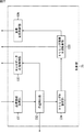
画像処理装置11は、光学系31、イメージャ32、デジタル信号処理部33、表示部34、制御部35、レンズ駆動部36、インタフェース制御部37、およびユーザインタフェース38から構成される。また、画像処理装置11には、記録メディア39およびDRAM(Dynamic Random Access Memory)40が接続されている。
The
光学系31は、図示せぬ撮像レンズを含む光学系として構成される。光学系31に入射した光は、CCD(Charge Coupled Device)等の撮像素子で構成されるイメージャ32により光電変換される。イメージャ32により光電変換された電気信号(アナログ信号)は、図示せぬA/D(Analog to Digital)変換部によりデジタル信号の画像データ(以下、適宜、RAWデータという)に変換され、デジタル信号処理部33に供給される。
The
デジタル信号処理部33は、イメージャ32からの画像データ(RAWデータ)に対して、所定の信号処理を施す。デジタル信号処理部33は、前処理部51、デモザイク処理部52、YC生成部53、解像度変換部54、被写体追尾部55、CODEC56、記録メディアインタフェース57、およびメモリコントローラ58を備えている。
The digital
前処理部51は、前処理として、イメージャ32からの画像データに対し、R,G,Bの黒レベルを所定のレベルにクランプするクランプ処理や、R,G,Bの色チャンネル間の補正処理等を施す。デモザイク処理部52は、前処理部51により前処理された画像データに対し、画像データの各画素がR,G,B全ての色成分を有するように、画素の色成分を補完するデモザイク処理を施す。
As preprocessing, the preprocessing
YC生成部53は、デモザイク処理部52によりデモザイク処理された、R,G,Bの画像データから、輝度(Y)信号および色(C)信号を生成(分離)する。解像度変換部54は、YC生成部53で処理された画像データに対して、解像度変換処理を実行する。
The
被写体追尾部55は、YC生成部53によって生成された輝度信号および色信号からなる画像データを基に、画像データに対応する入力画像における被写体を検出し、追尾する被写体追尾処理を実行する。
The
ここで、被写体の検出は、ユーザが入力画像を一瞥した場合に、ユーザが注目すると推
定される入力画像上の物体、つまりユーザが目を向けると推定される物体が被写体であるとして行われる。したがって、被写体は必ずしも人物に限られる訳ではない。
Here, the detection of the subject is performed on the assumption that the object on the input image that is estimated to be noticed by the user when the user glances at the input image, that is, the object that is estimated to be looked at by the user is the subject. Therefore, the subject is not necessarily limited to a person.
被写体追尾部55は、被写体追尾処理の結果得られた、入力画像における被写体が含まれる領域を表す被写体枠についてのデータを制御部35に供給する。なお、被写体追尾部55の詳細については、図2を参照して後述する。
The
CODEC56は、YC生成部53または解像度変換部54で生成された画像データや、DRAM40に記録された画像データを必要に応じて符号化し、記録メディアインタフェース57を介して記録メディア39に記録させたり、符号化された画像データを復号したりする。CODEC56で復号された画像データ、または解像度変換部54で得られた画像データは、表示部34に供給されて表示される。表示部34は、例えば液晶ディスプレイなどからなり、制御部35の制御に従ってデジタル信号処理部33から供給された画像データに対応する入力画像を表示する。
The
記録メディアインタフェース57は、制御部35の制御に基づいて、CODEC56により符号化された画像データを記録メディア39に記録させる。また、記録メディアインタフェース57には、例えば、CODEC56により符号化された画像データの他に、DRAM40からメモリコントローラ58により読み出され、所定の信号処理が施された画像データが供給され、記録メディア39に記録される。
The
メモリコントローラ58は、制御部35の制御に基づいて、YC生成部53または解像度変換部54で生成された画像データ(RAWデータ)をDRAM40に記録させるとともに、DRAM40からRAWデータを読み出し、デジタル信号処理部33の各部に供給する。
Under the control of the
制御部35は、インタフェース制御部37から供給される制御信号に応じて、画像処理装置11の各部を制御する。
The
例えば、制御部35は、デジタル信号処理部33に、各種の信号処理に用いられるパラメータ等を供給するとともに、デジタル信号処理部33からの、各種の信号処理の結果得られたデータを取得し、インタフェース制御部37に供給する。
For example, the
また、制御部35は、被写体追尾部55からの、入力画像における被写体が含まれる領域を表す被写体枠についてのデータに基づいて、表示部34に表示されている入力画像上に、被写体枠を表示させる。
Further, the
さらに、制御部35は、光学系31を構成する撮像レンズを駆動させたり、絞りなどを調節させたりするための制御信号をレンズ駆動部36に供給する。また、制御部35は、イメージャ32による入力画像の撮像も制御する。
Further, the
ユーザインタフェース38は、ユーザが画像処理装置11に対する指示を入力するときに操作されるボタンやレバー、スイッチ、マイクロホン等の入力装置、ユーザに対して情報を提示するランプやスピーカ等の出力装置などから構成される。
The
例えば、ユーザインタフェース38は、ユーザインタフェース38としてのボタンが操作されると、その操作に応じた制御信号を、インタフェース制御部37を介して制御部35に供給する。
For example, when a button as the
記録メディア39は、テープ、DVD(Digital Versatile Disc)、メモリカードなどの、画像処理装置11に対して着脱式の記録媒体であったり、ハードディスクなどの画像処理装置11に内蔵される固定式の記録媒体である。
The
DRAM40は、デジタル信号処理部33において生成された画像データ(RAWデータ)を適宜記録する。
The
[被写体追尾部の構成例]
次に、図2を参照して、図1の被写体追尾部55の構成例について説明する。
[Configuration example of subject tracking unit]
Next, a configuration example of the
図2の被写体追尾部55は、被写体マップ生成部71、被写体候補領域矩形化部72、被写体領域選択部73、および重み係数算出部74から構成される。
The
被写体マップ生成部71は、入力画像が有する輝度や色等の特徴毎に、入力画像の所定フレームの所定領域における特徴量を示す特徴量マップを生成し、重み係数算出部74に供給する。また、被写体マップ生成部71は、生成した特徴量マップと、重み係数算出部74から供給される特徴量毎の重み係数とに基づいて、入力画像における被写体の領域らしさを示す被写体マップを生成する。
The subject
より具体的には、被写体マップ生成部71は、特徴毎の特徴量マップの各領域の情報(特徴量)を、同じ位置にある領域毎に重み付き加算して被写体マップを生成する。被写体マップ生成部71は、生成した被写体マップを被写体候補領域矩形化部72に供給する。
More specifically, the subject
なお、各特徴量マップにおいて、より情報量の多い領域、つまり特徴量の多い領域に対応する入力画像上の領域は、被写体が含まれる可能性のより高い領域となり、したがって、各特徴量マップにより入力画像における被写体の含まれる領域を特定することができる。 In each feature amount map, a region having a larger amount of information, that is, a region on the input image corresponding to a region having a larger feature amount is a region having a higher possibility of including a subject. A region including a subject in the input image can be specified.
被写体候補領域矩形化部72は、被写体マップ生成部71からの被写体マップにおいて、被写体の候補となる領域、すなわち、被写体マップにおける情報量の多い領域を含む矩形領域を求め、その矩形領域の座標を表す座標情報を、被写体領域選択部73に供給する。また、被写体候補領域矩形化部72は、被写体マップ上で座標情報により表わされる矩形領域に関する情報(以下、領域情報という)を算出し、座標情報に対応付けて被写体領域選択部73に供給する。
The subject candidate
被写体領域選択部73は、追尾対象となる、注目すべき被写体が含まれる矩形領域である被写体領域を、被写体候補領域矩形化部72からの領域情報に基づいて矩形領域の中から選択し、その被写体領域の座標情報を制御部35(図1)および重み係数算出部74に供給する。
The subject
重み係数算出部74は、被写体マップ生成部71からの所定フレームの各特徴量マップ上の、被写体領域に対応する領域における特徴量のうち、相対的に大きい特徴量に対応する次フレームの特徴量マップを重み付けする重み係数を算出し、被写体マップ生成部71に供給する。
The weighting
このような構成により、被写体追尾部55は、入力画像のフレーム毎に、被写体領域を表す被写体枠を求めることができる。
With such a configuration, the
[被写体マップ生成部の構成例]
次に、図3を参照して、図2の被写体マップ生成部71の構成例について説明する。
[Configuration example of subject map generator]
Next, a configuration example of the subject
図3の被写体マップ生成部71は、特徴量マップ生成部111、帯域特徴量マップ生成部112、帯域特徴量マップ合成部113、および合成特徴量マップ合成部114から構成される。
3 includes a feature
特徴量マップ生成部111は、入力画像の所定フレームから、輝度や色といった特徴に関する情報(特徴量)を示す特徴量マップを特徴量毎に生成し、帯域特徴量マップ生成部112に供給する。
The feature amount
帯域特徴量マップ生成部112は、特徴量マップ生成部111からの各特徴量マップにおける特徴量から、所定の帯域成分の特徴量を所定の回数だけ抽出し、抽出したそれぞれの特徴量を示す帯域特徴量マップを生成し、重み係数算出部74および帯域特徴量マップ合成部113に供給する。
The band feature amount
帯域特徴量マップ合成部113は、帯域特徴量マップ生成部112からの帯域特徴量マップを、重み係数算出部74からの重み係数に基づいて特徴量毎に合成することで、合成特徴量マップを生成し、重み係数算出部74および合成特徴量マップ合成部114に供給する。
The band feature quantity map synthesis unit 113 synthesizes the band feature quantity map from the band feature quantity
合成特徴量マップ合成部114は、帯域特徴量マップ合成部113からの合成特徴量マップを、重み係数算出部74からの重み係数に基づいて合成することで、被写体マップを生成し、被写体候補領域矩形化部72(図2)に供給する。
The composite feature amount
ここで、以下においては、上述した帯域特徴量マップおよび合成特徴量マップを、単に、特徴量マップともいう。 Here, in the following, the band feature amount map and the combined feature amount map described above are also simply referred to as a feature amount map.
[被写体候補領域矩形化部の構成例]
次に、図4を参照して、図2の被写体候補領域矩形化部72の構成例について説明する。
[Configuration Example of Subject Candidate Area Rectification Unit]
Next, a configuration example of the subject candidate
図4の被写体候補領域矩形化部72は、2値化処理部131、ラベリング処理部132、矩形領域座標算出部133、および領域情報算出部134から構成される。
4 includes a binarization processing unit 131, a
2値化処理部131は、被写体マップ生成部71から供給された被写体マップにおける、入力画像の各画素に対応する情報を、所定の閾値に基づいて0または1のいずれかの値に2値化して、ラベリング処理部132に供給する。ここで、以下においては、被写体マップにおいて、入力画像の各画素に対応する情報を、単に、画素ともいう。
The binarization processing unit 131 binarizes information corresponding to each pixel of the input image in the subject map supplied from the subject
ラベリング処理部132は、2値化処理部131からの、2値化された被写体マップにおいて、1の値である画素が隣接する領域(以下、連結領域という)に対してラベリングし、矩形領域座標算出部133に供給する。
In the binarized subject map from the binarization processing unit 131, the
矩形領域座標算出部133は、ラベリング処理部132からの、連結領域がラベリングされた被写体マップにおいて、連結領域を含む(囲む)矩形領域の座標を算出し、その座標を表す座標情報を、被写体マップとともに領域情報算出部134に供給する。
The rectangular area coordinate
領域情報算出部134は、矩形領域座標算出部133からの被写体マップ上で座標情報により表される矩形領域に関する情報である領域情報を算出し、座標情報に対応付けて被写体領域選択部73(図1)に供給する。
The area
[被写体領域選択部の構成例]
次に、図5を参照して、被写体領域選択部73の構成例について説明する。
[Configuration example of subject area selection unit]
Next, a configuration example of the subject
図5の被写体領域選択部73は、領域情報比較部151および被写体領域決定部152から構成される。
The subject
領域情報比較部151は、被写体候補領域矩形化部72からの各矩形領域の領域情報と、領域情報記憶部153に記憶されている1フレーム前の被写体領域の領域情報とを比較し、比較結果を被写体領域決定部152に供給する。
The region
被写体領域決定部152は、領域情報比較部151からの比較結果に基づいて、1フレーム前の被写体領域の領域情報に最も近い領域情報に対応付けられている座標情報で表される矩形領域を被写体領域とする。被写体領域決定部152は、決定した被写体領域の座標情報を制御部35(図1)および重み係数算出部74(図2)に供給するとともに、被写体領域の領域情報を、領域情報記憶部153に供給する。
Based on the comparison result from the region
領域情報記憶部153は、被写体領域決定部152からの、被写体領域の領域情報を記憶する。領域情報記憶部153に記憶された被写体領域の領域情報は、1フレーム後に、領域情報比較部151に読み出される。
The area
[被写体追尾処理]
以下においては、画像処理装置11の被写体追尾処理について説明する。
[Subject tracking processing]
In the following, the subject tracking process of the
図6は、画像処理装置11の被写体追尾処理について説明するフローチャートである。被写体追尾処理は、例えば、ボタンとしてのユーザインタフェース38がユーザに操作されることで、画像処理装置11の動作モードが被写体追尾処理を実行する被写体追尾処理モードに遷移し、表示部34に表示されている入力画像において、追尾対象としての被写体の所定領域がユーザにより選択されたときに開始される。
FIG. 6 is a flowchart for describing subject tracking processing of the
ステップS11において、被写体追尾部55の被写体マップ生成部71は、被写体マップ生成処理を行い、被写体マップを生成して、被写体候補領域矩形化部72に供給する。
In step S <b> 11, the subject
[被写体マップ生成処理]
ここで、図7および図8を参照して、被写体マップ生成処理の詳細について説明する。図7は、被写体マップ生成処理について説明するフローチャートであり、図8は、被写体マップ生成処理の具体例を示す図である。
[Subject map generation processing]
Here, the details of the subject map generation process will be described with reference to FIGS. FIG. 7 is a flowchart for describing subject map generation processing, and FIG. 8 is a diagram illustrating a specific example of subject map generation processing.
図7のフローチャートのステップS31において、被写体マップ生成部71の特徴量マップ生成部111は、入力画像の所定フレームから、輝度や色等の特徴(特徴量毎)に特徴量マップを生成し、帯域特徴量マップ生成部112に供給する。
In step S31 of the flowchart of FIG. 7, the feature amount
具体的には、図8に示されるように、入力画像200から、輝度に関する情報を示す輝度情報マップF1、色に関する情報を示す色情報マップF2乃至FK、エッジに関する情報を示すエッジ情報マップF(K+1)乃至FMの、M種類の特徴量マップが生成される。
Specifically, as illustrated in FIG. 8, from the
輝度情報マップF1においては、入力画像の各画素から得られる輝度成分(輝度信号)Yが、入力画像の各画素に対応する情報となり、色情報マップF2乃至FKにおいては、入力画像の各画素から得られる色成分(色信号)R,G,Bが、入力画像の各画素に対応する情報となる。また、エッジ情報マップF(K+1)乃至FMにおいては、例えば、入力画像の各画素における0度、45度、90度、および135度の方向のエッジ強度が、入力画像の各画素に対応する情報となる。 In the luminance information map F 1, the luminance component (luminance signal) Y obtained from each pixel of the input image becomes the information corresponding to each pixel of the input image, the color information map F 2 to F K, the input image Color components (color signals) R, G, and B obtained from each pixel become information corresponding to each pixel of the input image. Further, in the edge information map F (K + 1) to F M, for example, 0 degrees of each pixel of the input image, 45 degrees, 90 degrees, and 135 degrees in the direction of the edge strength corresponding to each pixel of the input image Information.
なお、上述した特徴量マップについて、画素のR,G,Bの各成分の値の平均値を輝度情報マップF1の情報(特徴量)としてもよいし、色差成分Cr,Cbや、Lab色空間におけるa*座標成分およびb*座標成分を色情報マップF2乃至FKの情報としてもよい。また、0度、45度、90度、および135度以外の方向のエッジ強度をエッジ情報マップF(K+1)乃至FMの情報としてもよい。 Note that the feature amount map as described above, may be a luminance information map F 1 information an average value of each component of R, G, B pixel (features), the color difference components Cr, and Cb, Lab color The a * coordinate component and b * coordinate component in the space may be used as the information of the color information maps F 2 to F K. Also, 0 °, 45 °, 90 °, and the edge information in the direction of edge strength other than 135 degrees map F (K + 1) to be as the information of the F M.
ステップS32において、帯域特徴量マップ生成部112は、各特徴量マップにおける特徴量から、所定の帯域成分の特徴量をN回抽出し、抽出したそれぞれの特徴量を示す帯域特徴量マップを生成して、重み係数算出部74および帯域特徴量マップ合成部113に供給する。
In step S32, the band feature quantity
具体的には、図8に示されるように、輝度情報マップF1における輝度情報から、所定の帯域1乃至帯域Nの輝度情報が抽出され、その帯域それぞれの輝度情報を示す帯域輝度情報マップR11乃至R1Nが生成される。また、色情報マップF2乃至FKにおける色情報から、所定の帯域1乃至帯域Nの色情報が抽出され、その帯域それぞれの色情報を示す帯域色情報マップR21乃至R2N,…,RK1乃至RKNが生成される。さらに、エッジ情報マップF(K+1)乃至FMにおけるエッジ情報から、所定の帯域1乃至帯域Nのエッジ情報が抽出され、その帯域それぞれのエッジ情報を示す帯域エッジ情報マップR(K+1)1乃至R(K+1)N,…,RM1乃至RMNが生成される。このように、帯域特徴量マップ生成部112は、(M×N)種類の帯域特徴量マップを生成する。
Specifically, as shown in FIG. 8, the luminance information of a
ここで、帯域特徴量マップ生成部112の処理の一例について説明する。
Here, an example of processing of the band feature amount
例えば、帯域特徴量マップ生成部112は、各特徴量マップを用いて、互いに解像度の異なる複数の特徴量マップを生成し、それらの特徴量マップをその特徴量のピラミッド画像とする。例えば、レベルL1乃至レベルL8までの8つの解像度の階層のピラミッド画像が生成され、レベルL1のピラミッド画像が最も解像度が高く、レベルL1からレベルL8まで順番にピラミッド画像の解像度が低くなるものとする。
For example, the band feature quantity
この場合、特徴量マップ生成部111により生成された特徴量マップが、レベルL1のピラミッド画像とされる。また、レベルLi(但し、1≦i≦7)のピラミッド画像における、互いに隣接する4つの画素の画素値の平均値が、それらの画素と対応するレベルL(i+1)のピラミッド画像の1つの画素の画素値とされる。したがって、レベルL(i+1)のピラミッド画像は、レベルLiのピラミッド画像に対して縦横半分(割り切れない場合は切り捨て)の画像となる。
In this case, the feature amount map generated by the feature amount
また、帯域特徴量マップ生成部112は、複数のピラミッド画像のうち、互いに階層の異なる2つのピラミッド画像を選択し、選択したピラミッド画像の差分を求めて各特徴量の差分画像をN枚生成する。なお、各階層のピラミッド画像は、それぞれ大きさ(画素数)が異なるので、差分画像の生成時には、より小さい方のピラミッド画像が、より大きいピラミッド画像に合わせてアップコンバートされる。
Further, the band feature amount
例えば、帯域特徴量マップ生成部112は、各階層の特徴量のピラミッド画像のうち、レベルL6およびレベルL3、レベルL7およびレベルL3、レベルL7およびレベルL4、レベルL8およびレベルL4、並びにレベルL8およびレベルL5の各階層の組み合わせのピラミッド画像の差分を求める。これにより、合計5つの特徴量の差分画像が得られる。
For example, the band feature
具体的には、例えば、レベルL6およびレベルL3の組み合わせの差分画像が生成される場合、レベルL6のピラミッド画像が、レベルL3のピラミッド画像の大きさに合わせてアップコンバートされる。つまり、アップコンバート前のレベルL6のピラミッド画像の1つの画素の画素値が、その画素に対応する、アップコンバート後のレベルL6のピラミッド画像の互いに隣接するいくつかの画素の画素値とされる。そして、レベルL6のピラミッド画像の画素の画素値と、その画素と同じ位置にあるレベルL3のピラミッド画像の画素の画素値との差分が求められ、その差分が差分画像の画素の画素値とされる。 Specifically, for example, when a differential image of a combination of level L6 and level L3 is generated, the pyramid image at level L6 is up-converted according to the size of the pyramid image at level L3. That is, the pixel value of one pixel of the pyramid image of level L6 before up-conversion is the pixel value of several pixels adjacent to each other of the pyramid image of level L6 after up-conversion corresponding to that pixel. Then, the difference between the pixel value of the pixel of the level L6 pyramid image and the pixel value of the pixel of the level L3 pyramid image at the same position as the pixel is obtained, and the difference is set as the pixel value of the pixel of the difference image. The
このように、差分画像を生成することで、特徴量マップにバンドパスフィルタを用いたフィルタ処理を施すように、特徴量マップから所定の帯域成分の特徴量を抽出することができる。 In this way, by generating the difference image, it is possible to extract the feature amount of a predetermined band component from the feature amount map so that the feature amount map is subjected to filter processing using a bandpass filter.
なお、以上の説明において、特徴量マップから抽出される帯域の幅は、差分画像を求める際の、ピラミッド画像の各階層の組み合わせによって決まるが、この組み合わせは任意に決定される。 In the above description, the width of the band extracted from the feature map is determined by the combination of each layer of the pyramid image when obtaining the difference image, but this combination is arbitrarily determined.
また、所定の帯域成分の特徴量の抽出は、上述した差分画像による手法に限らず、他の手法を用いるようにしてもよい。 Further, the extraction of the feature amount of the predetermined band component is not limited to the above-described method using the difference image, and other methods may be used.
図7のフローチャートに戻り、ステップS33において、帯域特徴量マップ合成部113は、帯域特徴量マップ生成部112からの帯域特徴量マップを、重み係数算出部74からの重み係数群WRに基づいて特徴量毎に合成する。帯域特徴量マップ合成部113は、合成した帯域特徴量マップ(合成特徴量マップ)を、重み係数算出部74および合成特徴量マップ合成部114に供給する。
Returning to the flowchart of FIG. 7, in step S33, the band feature amount map synthesis unit 113, a band feature quantity map from the band feature amount
具体的には、図8に示されるように、帯域輝度情報マップR11乃至R1Nは、重み係数算出部74からの帯域輝度情報マップ毎の重みである重み係数w11乃至w1Nにより重み付き加算され、合成特徴量マップC1が求められる。また、帯域色情報マップR21乃至R2N,…,RK1乃至RKNは、重み係数算出部74からの帯域色情報マップ毎の重みである重み係数w21乃至w2N,…,wK1乃至wKNにより重み付き加算され、合成特徴量マップC2乃至CKが求められる。さらに、帯域エッジ情報マップR(K+1)1乃至R(K+1)N,…,RM1乃至RMNは、重み係数算出部74からの帯域エッジ情報マップ毎の重みである重み係数w(K+1)1乃至w(K+1)N,…,wM1乃至wMNにより重み付き加算され、合成特徴量マップCK+1乃至CMが求められる。このように、帯域特徴量マップ合成部113は、M種類の合成特徴量マップを生成する。なお、重み係数群WRの詳細については後述するが、重み係数群WRの各重み係数は、0乃至1の値を有する。但し、1回目の被写体マップ生成処理においては、重み係数群WRの各重み係数は全て1とされ、帯域特徴量マップは、重みなしで加算される。
Specifically, as shown in FIG. 8, the band luminance information maps R 11 to R 1N are weighted by weighting factors w 11 to w 1N that are weights for each band luminance information map from the weighting
ステップS34において、合成特徴量マップ合成部114は、帯域特徴量マップ合成部113からの合成特徴量マップを、重み係数算出部74からの重み係数群WCに基づいて合成することで、被写体マップを生成し、被写体候補領域矩形化部72に供給する。
In step S34, the synthetic characteristic amount
具体的には、図8に示されるように、合成特徴量マップC1乃至CMは、重み係数算出部74からの帯域輝度情報マップ毎の重みである重み係数w1乃至wMを用いて線形結合される。さらに、線形結合の結果得られたマップの画素値に、予め求められた重みである被写体重みが乗算され正規化されて、被写体マップ201を求める。なお、重み係数群WCの詳細については後述するが、重み係数群WCの各重み係数は、0乃至1の値を有する。但し、1回目の被写体マップ生成処理においては、重み係数群WCの各重み係数は全て1とされ、合成特徴量マップは、重みなしで線形結合される。
Specifically, as illustrated in FIG. 8, the combined feature amount maps C 1 to C M use weighting factors w 1 to w M that are weights for each band luminance information map from the weighting
つまり、これから求めようとする被写体マップ上の注目する位置(画素)を注目位置とすると、各合成特徴量マップの注目位置と同じ位置(画素)の画素値に、合成特徴量マップごとの重み係数が乗算され、重み係数の乗算された画素値の総和が、注目位置の画素値とされる。さらに、このようにして求められた被写体マップの各位置の画素値に、被写体マップに対して予め求められた被写体重みが乗算されて正規化され、最終的な被写体マップとされる。例えば、正規化は、被写体マップの各画素の画素値が、0から255までの間の値となるようになされる。 In other words, if the target position (pixel) on the subject map to be obtained is the target position, the weight coefficient for each composite feature map is set to the pixel value at the same position (pixel) as the target position of each composite feature map. And the sum of the pixel values multiplied by the weighting coefficient is used as the pixel value at the target position. Further, the pixel value at each position of the subject map obtained in this way is multiplied by a subject weight obtained in advance with respect to the subject map and normalized to obtain a final subject map. For example, the normalization is performed so that the pixel value of each pixel of the subject map becomes a value between 0 and 255.
以上のようにして、被写体マップ生成部71は、特徴量マップから、帯域特徴量マップおよび合成特徴量マップを生成することにより、被写体マップを生成する。
As described above, the subject
図6のフローチャートに戻り、ステップS12において、被写体候補領域矩形化部72は、被写体候補領域矩形化処理を行い、被写体マップ生成部71からの被写体マップにおいて、被写体の候補となる領域を含む矩形領域を求める。
Returning to the flowchart of FIG. 6, in step S <b> 12, the subject candidate
[被写体候補領域矩形化処理]
ここで、図9および図10を参照して、被写体候補領域矩形化処理の詳細について説明する。図9は、被写体候補領域矩形化処理について説明するフローチャートであり、図10は、被写体候補領域矩形化処理の具体例を示す図である。
[Subject candidate area rectangle processing]
Here, with reference to FIG. 9 and FIG. 10, details of the subject candidate area rectangularization process will be described. FIG. 9 is a flowchart for describing the subject candidate area rectangularization process, and FIG. 10 is a diagram illustrating a specific example of the subject candidate area rectangularization process.
図9のフローチャートのステップS51において、被写体候補領域矩形化部72の2値化処理部131は、被写体マップ生成部71から供給された被写体マップにおける情報を、所定の閾値に基づいて0または1のいずれかの値に2値化し、ラベリング処理部132に供給する。
In step S51 of the flowchart of FIG. 9, the binarization processing unit 131 of the subject candidate
より具体的には、2値化処理部131は、図10の上から1番目に示される、0から255までの間の値である被写体マップ201の各画素の画素値に対して、例えば、閾値127より小さい値の画素値を0とし、127より大きい値の画素値を1とする。これによって、図10の上から2番目に示されるような2値化マップ202が得られる。図10で示される2値化マップ202においては、白で示される部分(画素)が1の画素値を有し、黒で示される部分(画素)が0の画素値を有している。なお、ここでは、閾値を127であるものとしたが、他の値であってもよい。
More specifically, the binarization processing unit 131 performs, for example, a pixel value of each pixel of the
ステップS52において、ラベリング処理部132は、2値化処理部131から2値化マップ202(2値化された被写体マップ)において、例えば、モルフォロジー演算等によって得られる、1である画素値の画素が隣接する連結領域に対してラベリングし、矩形領域座標算出部133に供給する。
In step S52, the
より具体的には、例えば、図10の上から3番目に示されるように、2値化マップ202においては、連結領域211が、ラベル「1」でラベリングされ、連結領域212が、ラベル「2」でラベリングされる。
More specifically, for example, as shown third from the top in FIG. 10, in the
ステップS53において、矩形領域座標算出部133は、ラベリング処理部132からの2値化マップ202において、連結領域を含む(囲む)矩形領域の座標を算出し、その座標を表す座標情報を、2値化マップ202とともに領域情報算出部134に供給する。
In step S <b> 53, the rectangular area coordinate
より具体的には、図10の上から4番目に示されるように、2値化マップ202において、ラベル「1」でラベリングされた連結領域211を外側から囲む矩形枠(外接枠)221が検出され、その矩形枠の、例えば図中左上および右下の頂点の座標が求められる。また、ラベル「2」でラベリングされた連結領域212を外側から囲む矩形枠222が検出され、その矩形枠の、例えば図中左上および右下の頂点の座標が求められる。
More specifically, as shown in the fourth from the top in FIG. 10, in the
ステップS54において、領域情報算出部134は、矩形領域座標算出部133からの座標情報と、被写体マップ生成部71からの被写体マップに基づいて、被写体マップ上で矩形枠に囲まれる矩形領域についての領域情報を算出する。
In step S <b> 54, the region
より具体的には、領域情報算出部134は、2値化マップ202における矩形枠221,222を表す、矩形領域座標算出部133からの座標情報に基づいて、矩形枠のサイズおよび中心位置の座標を、矩形領域についての領域情報として算出する。領域情報算出部134は、算出した領域情報を、矩形領域座標算出部133からの座標情報に対応付けて被写体領域選択部73に供給する。
More specifically, the area
以上のようにして、被写体候補領域矩形化部72は、被写体マップにおいて、注目すべき被写体の候補となる各領域を囲む矩形枠、および、被写体マップ上でその矩形枠で囲まれる領域の特徴を表す領域情報を求める。
As described above, the subject candidate
図6のフローチャートに戻り、ステップS13において、被写体領域選択部73は、被写体領域選択処理を行い、注目すべき被写体が含まれる矩形領域である被写体領域を、領域情報算出部134の領域情報に基づいて矩形領域の中から選択する。
Returning to the flowchart of FIG. 6, in step S <b> 13, the subject
[被写体領域選択処理]
ここで、図11のフローチャートを参照して、被写体領域選択処理の詳細について説明する。
[Subject area selection processing]
Here, the details of the subject area selection processing will be described with reference to the flowchart of FIG.
ステップS71において、領域情報比較部151は、被写体候補領域矩形化部72からの各矩形領域の領域情報と、領域情報記憶部153に記憶されている1フレーム前の被写体領域の領域情報とを比較し、比較結果を被写体領域決定部152に供給する。
In step S <b> 71, the region
より具体的には、例えば、領域情報比較部151は、被写体候補領域矩形化部72からの、被写体マップ上での各矩形領域を囲む矩形枠のサイズと、領域情報記憶部153に記憶されている1フレーム前の被写体領域を囲む矩形枠(被写体枠)のサイズとを比較する。また、例えば、領域情報比較部151は、被写体候補領域矩形化部72からの、被写体マップ上での各矩形領域を囲む矩形枠の中心位置の座標と、領域情報記憶部153に記憶されている1フレーム前の被写体領域を囲む矩形枠(被写体枠)の中心位置の座標とを比較する。
More specifically, for example, the region
ステップS72において、被写体領域決定部152は、領域情報比較部151からの比較結果に基づいて、1フレーム前の被写体領域を囲む矩形枠(被写体枠)のサイズまたは中心位置の座標に最も近い矩形枠のサイズまたは中心位置を有する矩形領域を被写体領域とする。被写体領域決定部152は、決定した被写体領域の座標情報を制御部35および重み係数算出部74に供給するとともに、被写体領域の領域情報(被写体枠のサイズまたは中心位置)を、領域情報記憶部153に供給する。
In step S72, the subject
但し、1回目の被写体領域選択処理において、領域情報記憶部153には、1フレーム前の被写体領域の領域情報は記憶されていないので、被写体追尾処理の開始時にユーザによって選択された被写体の所定領域(以下、初期選択領域という)を含む矩形領域が被写体領域とされる。
However, in the first subject region selection process, the region
以上のようにして、被写体領域選択部73は、被写体の候補となる矩形領域の中から、注目すべき被写体の被写体領域を選択する。
As described above, the subject
[重み係数の算出]
図6のフローチャートに戻り、ステップS14において、重み係数算出部74は、被写体マップ生成部71からの帯域特徴量マップおよび合成特徴量マップと、被写体領域選択部73からの被写体領域を表す座標情報とに基づいて、図8で示された重み係数群WR,WCを算出する。
[Calculation of weighting factor]
Returning to the flowchart of FIG. 6, in step S <b> 14, the weight
より具体的には、図12に示されるように、所定の帯域特徴量マップRmn(1≦m≦M,1≦n≦N)上の、被写体領域を表す被写体枠231に対応する矩形領域内の特徴量(情報量)の和を被写体領域特徴量和rmnとした場合、図13の上側に示されるような重み係数群WRが算出される。
More specifically, as shown in FIG. 12, a rectangular area corresponding to a
図13の重み係数群WRにおける係数のそれぞれは、図8で示された重み係数w11乃至wMNのそれぞれに対応している。なお、図13において、Max[a,…,z]は、値a乃至zのうちの最大値を表すものとする。 Each coefficient in the weight coefficient group W R of FIG. 13 corresponds to each of the weight coefficients w 11 to w MN shown in FIG. In FIG. 13, Max [a,..., Z] represents the maximum value among the values a to z.
例えば、図13の重み係数群WRにおける上から1番目の行の各係数は、図8で示された、「帯域1」である特徴量毎の帯域特徴量マップR11乃至RM1についての重み係数w11乃至wM1を示している。図13に示されるように、重み係数w11乃至wM1は、分母が帯域特徴量マップR11乃至RM1それぞれについての被写体領域特徴量和r11乃至rM1のうちの最大値とされ、分子が帯域特徴量マップR11乃至RM1それぞれについての被写体領域特徴量和r11乃至rM1とされる係数であり、0乃至1の値をとる。
For example, each coefficient of the first row from the top in the weight coefficient group W R of FIG. 13, shown in FIG. 8, "
同様に、図13の重み係数群WRにおける上からN番目の行の各係数は、図8で示された、「帯域N」である特徴量毎の帯域特徴量マップR1N乃至RMNについての重み係数w1N乃至wMNを示している。図13に示されるように、重み係数w1N乃至wMNは、分母が帯域特徴量マップR1N乃至RMNそれぞれについての被写体領域特徴量和r1N乃至rMNのうちの最大値とされ、分子が帯域特徴量マップR1N乃至RMNそれぞれについての被写体領域特徴量和r1N乃至rMNとされる係数であり、0乃至1の値をとる。 Similarly, the coefficients of the N-th row from the top in the weight coefficient group W R of FIG. 13, shown in FIG. 8, the band feature amount map feature quantity per a "band N" R 1N to R MN The weighting factors w 1N to w MN are shown. As shown in FIG. 13, the weight coefficients w 1N to w MN are denominators that are the maximum values of the subject area feature amount sums r 1N to r MN for the band feature amount maps R 1N to R MN, respectively. Are coefficients that are subject area feature amount sums r 1N to r MN for the band feature amount maps R 1N to R MN, respectively, and take values of 0 to 1.
すなわち、重み係数w1n乃至wMnによれば、「帯域n」である特徴量毎の帯域特徴量マップR1n乃至RMnにおいて、被写体領域特徴量和が最大となる特徴量の帯域特徴量マップに最大値1となる重み付けがされ、その他の帯域特徴量マップには、被写体領域特徴量和に応じた重み付けがされる。 That is, according to the weighting factors w 1n to w Mn , the band feature amount map of the feature amount that maximizes the subject area feature amount sum in the band feature amount maps R 1n to R Mn for each feature amount that is “band n”. The other band feature amount maps are weighted according to the subject region feature amount sum.
また、所定の合成特徴量マップCm(1≦m≦M)上の、被写体領域を表す矩形枠221に対応する矩形領域内の特徴量(情報量)の和を被写体領域特徴量和cmとした場合、図13の下側に示されるような重み係数群WCが算出される。
In addition, the sum of the feature amounts (information amounts) in the rectangular area corresponding to the
図13の重み係数群WCにおける係数のそれぞれは、図8で示された重み係数w1乃至wMのそれぞれに対応している。 Each coefficient in the weight coefficient group W C of FIG. 13 corresponds to each of the weighting coefficients w 1 to w M shown in FIG.
つまり、図13の重み係数群WCにおける各係数は、図8で示された、特徴量毎の合成特徴量マップC1乃至CMについての重み係数w1乃至wMを示している。図13に示されるように、重み係数w1乃至wMは、分母が合成特徴量マップC1乃至CMそれぞれについての被写体領域特徴量和c1乃至cMのうちの最大値とされ、分子が合成特徴量マップC1乃至CMそれぞれについての被写体領域特徴量和c1乃至cMとされる係数であり、0乃至1の値をとる。 That is, each coefficient in the weight coefficient group W C in FIG. 13 indicates the weight coefficients w 1 to w M for the combined feature amount maps C 1 to C M for each feature amount shown in FIG. As shown in FIG. 13, the weighting factors w 1 to w M are the maximum values of the subject area feature amount sums c 1 to c M for the combined feature amount maps C 1 to C M as the denominators. Are coefficients that are subject area feature amount sums c 1 to c M for each of the combined feature amount maps C 1 to C M , and take values of 0 to 1.
すなわち、重み係数w1乃至wmによれば、特徴量毎の合成特徴量マップC1乃至CMにおいて、被写体領域特徴量和が最大となる特徴量の合成特徴量マップに最大値1となる重み付けがされ、その他の帯域特徴量マップには、被写体領域特徴量和に応じた重み付けがされる。
That is, according to the weighting coefficients w 1 to w m, made in synthetic feature amount maps C 1 to C M for each feature quantity, the
重み係数算出部74は、算出した重み係数群WRを、被写体マップ生成部71の帯域特徴量マップ合成部113に供給するとともに、重み係数群WCを、被写体マップ生成部71の合成特徴量マップ合成部114に供給する。図6のフローチャートにおいては、ステップS14の後、次フレームについての被写体追尾処理が実行され、この処理が1フレーム毎に繰り返される。
Weight
以上の処理によれば、入力画像の所定のフレームについての特徴量毎の特徴量マップにおける、そのフレームで選択された被写体領域に対応する領域の特徴量の相対的な大きさに応じて、次フレームについての特徴量毎の特徴量マップに対する重み係数が決定される。したがって、フレーム間で特徴量が変動するような場合であっても、複数の特徴量のうちの被写体を最もよく表す特徴量の特徴量マップが最も大きく重み付けされた被写体マップが生成されるので、被写体の状態が変動するような環境下でも、被写体をより安定して追尾することが可能となる。 According to the above processing, in the feature amount map for each feature amount for a predetermined frame of the input image, the following is performed according to the relative size of the feature amount of the region corresponding to the subject region selected in the frame. A weighting factor for the feature amount map for each feature amount of the frame is determined. Therefore, even when the feature amount varies between frames, a feature map of the feature amount that best represents the subject among the plurality of feature amounts is generated with the most weighted subject map. Even in an environment where the state of the subject fluctuates, the subject can be tracked more stably.
また、被写体領域は、被写体全体を含むように決定されるので、被写体の一部の領域の状態が変動するような環境下でも、被写体をより安定して追尾することができる。 In addition, since the subject area is determined so as to include the entire subject, the subject can be tracked more stably even in an environment in which the state of a partial area of the subject fluctuates.
特に、従来の被写体追尾の手法において、被写体領域内のいずれかの座標(またはその座標を含む一部領域)が同定されるような場合では、被写体全体を追尾することができず、AF(Auto Focus)やAE(Auto Exposure)、ACC(Auto Color Control)の検波枠を正しく設定することができなかった。また、被写体領域内で特徴量が同一である同一特徴量領域が同定されるような場合では、上述の場合よりは検波枠を設定する精度を上げることができるが、同一特徴量領域は、被写体領域のごく一部に過ぎないことが多く、十分な検波精度は得られなかった。 In particular, when any of the coordinates in the subject area (or a partial area including the coordinates) is identified in the conventional subject tracking method, the entire subject cannot be tracked, and AF (Auto The detection frame for Focus, AE (Auto Exposure), and ACC (Auto Color Control) could not be set correctly. In addition, in the case where the same feature amount region having the same feature amount in the subject region is identified, the accuracy of setting the detection frame can be improved as compared with the above case. In many cases, it was only a small part of the area, and sufficient detection accuracy could not be obtained.
一方、上述した被写体追尾処理によれば、被写体全体を含む被写体領域を同定できるので、検波精度を上げることができ、ひいては、追尾結果を様々なアプリケーションに適用することが可能となる。 On the other hand, according to the subject tracking process described above, the subject area including the entire subject can be identified, so that the detection accuracy can be improved, and the tracking result can be applied to various applications.
また、従来の被写体追尾の手法には、例えば、人間の全体像を学習により辞書に登録する等して、人間を検出・追尾するものもあるが、辞書に登録されていない人間以外の被写体を追尾することはできない。さらに、辞書に登録される情報(画像)の量は膨大な量となるため、装置規模が大きくなってしまう。 In addition, conventional subject tracking methods include, for example, a method for detecting and tracking a human by registering an entire image of a human in a dictionary by learning, but a non-human subject that is not registered in the dictionary can be detected. It cannot be tracked. Furthermore, since the amount of information (images) registered in the dictionary is enormous, the apparatus scale becomes large.
一方、上述した被写体追尾処理によれば、任意の被写体を検出・追尾することができる上に、辞書等に膨大な量の情報を登録する必要がないので、装置規模をコンパクトにすることができる。 On the other hand, according to the subject tracking process described above, an arbitrary subject can be detected and tracked, and since it is not necessary to register a huge amount of information in a dictionary or the like, the apparatus scale can be made compact. .
以上においては、特徴量として、輝度成分、色成分、およびエッジ方向を用いるものとしたが、これに限らず、例えば、動き情報等を加えるようにしてもよい。また、用いられる特徴量は、例えば、輝度成分と色成分のような、相補的な関係にあるものが好適であり、適宜、選択されるようにしてもよい。 In the above description, the luminance component, the color component, and the edge direction are used as the feature amount. However, the present invention is not limited to this, and for example, motion information or the like may be added. In addition, the feature amount used is preferably a complementary relationship such as a luminance component and a color component, and may be appropriately selected.
また、以上においては、M×(N+1)種類の特徴量マップに対応して、M×(N+1)種類の重み係数を算出するようにしたが、一部の特徴量マップに対応する重み係数のみを、適宜算出するようにすることで、画像処理装置11における演算量を抑えることができる。例えば、合成特徴量マップC1乃至CMのM種類の特徴量マップに対応する重み係数w1乃至wMのみを算出するようにしてもよい。
In the above description, M × (N + 1) types of weighting coefficients are calculated corresponding to M × (N + 1) types of feature amount maps. However, only weighting factors corresponding to some feature amount maps are calculated. Is appropriately calculated, the amount of calculation in the
さらに、以上においては、領域情報算出部134は、矩形領域の領域情報として、矩形枠のサイズおよび中心位置の座標を算出するようにしたが、矩形領域内の画素値の積分値やピーク値(最大値)を算出するようにしてもよい。この場合、被写体領域選択処理(図11)においては、1フレーム前の被写体領域内の画素値の積分値またはピーク値に最も近い領域内の画素値の積分値またはピーク値を有する矩形領域が被写体領域とされる。
Further, in the above, the area
ところで、画像処理装置11が、静止画像を撮像するデジタルスチルカメラとして構成される場合、ユーザは、表示部34に表示されている動画像(ファインダ画像)を確認しながら、所望のタイミングでシャッタ操作を行うことで、静止画像を撮像する。
By the way, when the
このように構成される画像処理装置11には、上述した被写体追尾処理の追尾結果を適用したアプリケーションの一例として、ユーザによるシャッタ操作により撮像した静止画像(以下、撮像画像という)から、追尾した被写体を含む複数のトリミング画像を生成するトリミング処理を実行させることができる。
The
[制御部の機能構成例]
ここで、図14を参照して、上述した被写体追尾処理によって追尾した被写体を含む複数のトリミング画像を生成するトリミング処理を実行する制御部35の機能構成例について説明する。
[Functional configuration example of control unit]
Here, a functional configuration example of the
図14の制御部35は、操作判定部331、座標情報取得部332、RAWデータ記録制御部333、トリミング枠設定部334、トリミング画像生成制御部335、および画像記録制御部336を備えている。
14 includes an
操作判定部331は、ユーザインタフェース制御部37からの制御信号に基づいて、ユーザインタフェース38としてのシャッタボタンが操作されたか否かを判定する。操作判定部331は、シャッタボタンが操作された場合、イメージャ32に、撮像を指示する情報を供給する。これにより、デジタル信号処理部33には、撮像画像に対応するRAWデータが供給される。また、操作判定部331は、シャッタボタンが操作された旨の情報を、座標情報取得部332およびRAWデータ記録制御部333に供給する。
The
座標情報取得部332は、操作判定部331からの情報に応じて、被写体追尾部55から供給されてくる、撮像画像に対応するフレームについての被写体領域の座標情報を取得し、トリミング枠設定部334に供給する。
The coordinate
RAWデータ記録制御部333は、操作判定部331からの情報に応じて、メモリコントローラ58を制御し、撮像画像に対応するフレームについてのRAWデータをDRAM40に記録させる。
The RAW data recording
トリミング枠設定部334は、座標情報取得部332からの座標情報に基づいて、撮像画像に対応するフレームにおいて、座標情報取得部332からの座標情報で表される被写体領域を含む複数のトリミング枠を設定し、そのトリミング枠を表す情報をトリミング画像生成制御部335に供給する。
Based on the coordinate information from the coordinate
トリミング画像生成制御部335は、デジタル信号処理部33の各部を制御し、デジタル信号処理部33に、DRAM40に記録されているRAWデータを読み出させ、トリミング枠設定部334からのトリミング枠を表す情報に基づいて、複数のトリミング画像を生成させる。また、トリミング画像生成制御部335は、複数のトリミング画像を生成させた旨の情報を、画像記録制御部336に供給する。
The trimming image
画像記録制御部336は、記録メディアインタフェース57を制御し、トリミング画像生成制御部335からの情報に基づいて、デジタル信号処理部33において生成されたトリミング画像を記録メディア39に記録させる。
The image
[トリミング処理]
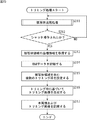
次に、図15のフローチャートを参照して、画像処理装置11によるトリミング処理について説明する。
[Trimming]
Next, trimming processing by the
ステップS311において、被写体追尾部55は、図6のフローチャートで説明した被写体追尾処理を実行し、被写体領域の座標情報を制御部35に供給する。
In step S <b> 311, the
ステップS312において、操作判定部331は、ユーザインタフェース制御部37からの制御信号に基づいて、ユーザによるシャッタ操作がされたか否かを判定する。
In step S <b> 312, the
ステップS312においては、ユーザによりシャッタ操作がされるまで、ステップS311,S312の処理が繰り返され、シャッタ操作がされたと判定された場合、操作判定部331は、イメージャ32に撮像を指示する情報を供給する。また、操作判定部331は、シャッタ操作がされた旨の情報を、座標情報取得部332およびRAWデータ記録制御部333に供給し、処理はステップS313に進む。
In step S312, the processes in steps S311 and S312 are repeated until the shutter operation is performed by the user, and when it is determined that the shutter operation is performed, the
ステップS313において、座標情報取得部332は、操作判定部331から、ユーザによりシャッタ操作がされた旨の情報が供給されると、撮像画像に対応するフレーム(以下、シャッタフレームともいう)についての、被写体追尾部55からの被写体領域の座標情報を取得し、トリミング枠設定部334に供給する。
In step S313, when the information indicating that the shutter operation is performed by the user is supplied from the
ステップS314において、RAWデータ記録制御部333は、ユーザによりシャッタ操作がされた旨の情報が供給されると、メモリコントローラ58を制御し、シャッタフレームについてのRAWデータをDRAM40に記録させる。
In step S <b> 314, when the information indicating that the shutter operation has been performed by the user is supplied, the RAW data
ステップS315において、トリミング枠設定部334は、座標情報取得部332からの座標情報に基づいて、シャッタフレームにおいて、座標情報取得部332からの座標情報で表される被写体領域を含む複数のトリミング枠を設定する。
In step S <b> 315, the trimming
ここで、図16乃至図18を参照して、トリミング枠設定部334によるトリミング枠の設定について説明する。
Here, the setting of the trimming frame by the trimming
図16は、撮像画像における被写体領域を表す被写体枠Hの例を示している。被写体枠Hは、座標情報取得部332からの座標情報(例えば、矩形領域左上および右下の頂点の座標)によって与えられる。また、図16においては、被写体枠Hの幅および高さは、それぞれWidthおよびHeightで示され、被写体枠Hの中心位置の座標は、C(Xc,Yc)で示される。 FIG. 16 shows an example of a subject frame H that represents a subject region in a captured image. The subject frame H is given by coordinate information from the coordinate information acquisition unit 332 (for example, the coordinates of the upper left and lower right vertices of the rectangular area). In FIG. 16, the width and height of the subject frame H are indicated by Width and Height, respectively, and the coordinates of the center position of the subject frame H are indicated by C (Xc, Yc).
図16で示されるような被写体領域の座標情報が供給された場合、トリミング枠設定部334は、例えば、図17で示されるトリミング枠Tr_0を設定する。
When the coordinate information of the subject area as shown in FIG. 16 is supplied, the trimming
図17において、トリミング枠Tr_0は、幅(Width×K)、高さ(Width×K×P)の矩形領域として設定されている。ここで、値Kは、予め決められた定数であり、値Pは、撮像画像のアスペクト比を示している。また、トリミング枠Tr_0の中心位置の座標は、図16の被写体枠Hと同様、C(Xc,Yc)で与えられている。すなわち、図17で示されるトリミング枠Tr_0は、被写体枠Hをその中心に含むトリミング枠となる。 In FIG. 17, the trimming frame Tr_0 is set as a rectangular area having a width (Width × K) and a height (Width × K × P). Here, the value K is a predetermined constant, and the value P indicates the aspect ratio of the captured image. Further, the coordinates of the center position of the trimming frame Tr_0 are given by C (Xc, Yc) as in the subject frame H of FIG. That is, the trimming frame Tr_0 shown in FIG. 17 is a trimming frame including the subject frame H at the center thereof.
そして、トリミング枠設定部334は、図17で示されるトリミング枠Tr_0を基準として、撮像画像において、例えば、トリミング枠Tr_0を上、下、左、右、左上、右上、左下、右下の8方向に、撮像画像からはみ出さない範囲でずらしたトリミング枠を設定する。
Then, the trimming
具体的には、トリミング枠設定部334は、図18の左側に示されるように、トリミング枠Tr_0(図中、破線で示される枠)を撮像画像からはみ出さない範囲で左下にずらしたトリミング枠Tr_1を、複数のトリミング枠の1つとして設定する。また、トリミング枠設定部334は、図18の右側に示されるように、トリミング枠Tr_0(図中、破線で示される枠)を撮像画像からはみ出さない範囲で右上にずらしたトリミング枠Tr_2を、複数のトリミング枠の1つとして設定する。
Specifically, as shown on the left side of FIG. 18, the trimming
このようにして、撮像画像において、被写体領域を含む複数のトリミング枠が設定される。トリミング枠設定部334は、設定した複数のトリミング枠を表す情報をトリミング画像生成制御部335に供給する。
In this way, a plurality of trimming frames including the subject area are set in the captured image. The trimming
図15のフローチャートに戻り、ステップS316において、トリミング画像生成制御部335は、トリミング枠設定部334から複数のトリミング枠を表す情報が供給されると、デジタル信号処理部33の各部を制御する。すなわち、トリミング画像生成制御部335は、デジタル信号処理部33に、DRAM40に記録されているRAWデータを読み出させ、トリミング枠設定部334からのトリミング枠を表す情報に基づいて、複数のトリミング画像を生成させる。また併せて、トリミング画像生成制御部335は、トリミングされていない撮像画像(以下、適宜、本画像という)を生成させる。そして、トリミング画像生成制御部335は、複数のトリミング画像を生成させた旨の情報を、画像記録制御部336に供給する。
Returning to the flowchart of FIG. 15, when information representing a plurality of trimming frames is supplied from the trimming
ステップS317において、画像記録制御部336は、トリミング画像生成制御部335から、複数のトリミング画像を生成させた旨の情報が供給されると、記録メディアインタフェース57を制御し、デジタル信号処理部33において生成された本画像および複数のトリミング画像を記録メディア39に記録させる。このとき、画像記録制御部336は、本画像とトリミング画像とを、記録メディア39においてそれぞれ異なるフォルダに記録させる。
In step S 317, the image
以上の処理によれば、ユーザのシャッタ操作により撮像された撮像画像において、被写体領域を含む複数のトリミング枠が設定されて、複数のトリミング画像が生成される。このとき、ユーザは、シャッタ操作を行うのみなので、撮影後の面倒な操作や、撮影時の高度な技術を必要とせずに、好適なトリミング画像を提供することが可能となる。 According to the above processing, a plurality of trimming frames including a subject area are set in a captured image captured by a user's shutter operation, and a plurality of trimmed images are generated. At this time, since the user only performs the shutter operation, it is possible to provide a suitable trimmed image without requiring a troublesome operation after shooting and a high level technique at the time of shooting.
また、本来ユーザのシャッタ操作により撮像された撮像画像(本画像)とトリミング画像とが、記録メディア39においてそれぞれ異なるフォルダに記録されるので、画角は異なっていても同一の被写体が撮像された画像が混在することがなくなり、ユーザの混乱を避けることができる。
In addition, since the captured image (main image) originally captured by the user's shutter operation and the trimmed image are recorded in different folders on the
以上においては、被写体領域を含む複数のトリミング枠を設定する構成について説明したが、トリミング画像における被写体の位置、つまり、トリミング画像の構図はあまり考慮されていなかった。 In the above description, the configuration for setting a plurality of trimming frames including the subject area has been described, but the position of the subject in the trimmed image, that is, the composition of the trimmed image has not been considered much.
そこで、以下においては、トリミング画像の構図を考慮するようにしたトリミング枠を設定する構成について説明する。 Therefore, in the following, a configuration for setting a trimming frame in consideration of the composition of the trimmed image will be described.
[制御部の他の機能構成例]
図19は、トリミング画像の構図を考慮するようにしたトリミング枠を設定する制御部35の機能構成例を示している。
[Other functional configuration examples of the control unit]
FIG. 19 shows a functional configuration example of the
なお、図19の制御部35において、図14の制御部35に設けられたものと同様の機能を備える構成については、同一名称および同一符号を付するものとし、その説明は、適宜省略するものとする。
In addition, in the
すなわち、図19の制御部35において、図14の制御部35と異なるのは、トリミング枠設定部334に代えて、トリミング枠設定部431を設けた点である。
That is, the
トリミング枠設定部431は、座標情報取得部332からの座標情報に基づいて、シャッタフレームにおいて、座標情報取得部332からの座標情報で表される被写体領域の位置が、予め決められた構図における所定位置となる複数のトリミング枠を設定し、そのトリミング枠を表す情報をトリミング画像生成制御部335に供給する。
Based on the coordinate information from the coordinate
[トリミング処理]
次に、図20のフローチャートを参照して、図19の制御部35を備える画像処理装置11によるトリミング処理について説明する。
[Trimming]
Next, trimming processing by the
なお、図20のフローチャートのステップS411乃至S414,S416乃至S417の処理は、図15のフローチャートのステップS311乃至S314,S316乃至S317の処理と基本的に同様であるので、その説明は省略する。 Note that the processing in steps S411 to S414, S416 to S417 in the flowchart in FIG. 20 is basically the same as the processing in steps S311 to S314 and S316 to S317 in the flowchart in FIG.
すなわち、ステップS415において、トリミング枠設定部431は、座標情報取得部332からの座標情報に基づいて、シャッタフレームにおいて、座標情報取得部332からの座標情報で表される被写体領域の位置が、予め決められた構図における所定位置となる複数のトリミング枠を設定する。
That is, in step S415, the trimming
例えば、トリミング枠設定部431は、シャッタフレームにおいて、座標情報取得部332からの座標情報で表される被写体領域の中心位置が、3分割構図において、3分割構図を水平方向および垂直方向に3分割する3分割線の交点(3分割線交点)となるような複数のトリミング枠を設定する。
For example, the trimming
具体的には、トリミング枠設定部431は、図21の左側に示されるように、撮像画像において、トリミング枠Tr_0(図17)と同一サイズで、3分割線を有するトリミング枠Tr_11を、その右上の3分割線交点と、被写体領域の中心位置の座標C(Xc,Yc)とが一致するように設定する。また、トリミング枠設定部431は、図21の右側に示されるように、撮像画像において、トリミング枠Tr_0と同一サイズで、3分割線を有するトリミング枠Tr_12を、その左下の3分割線交点と、被写体領域の中心位置の座標C(Xc,Yc)とが一致するように設定する。
Specifically, as shown on the left side of FIG. 21, the trimming
同様にして、トリミング枠設定部431は、3分割線を有するトリミング枠を、その左上および右下の3分割線交点と、被写体領域の中心位置の座標C(Xc,Yc)とが一致するように設定する。
Similarly, the trimming
すなわち、この場合、4つのトリミング枠が設定されるようになる。 That is, in this case, four trimming frames are set.
但し、被写体領域の中心位置によって、トリミング枠が撮像画像からはみ出してしまう場合には、そのトリミング枠は設定されない。 However, when the trimming frame protrudes from the captured image due to the center position of the subject area, the trimming frame is not set.
以上の処理によれば、ユーザによるシャッタ操作により撮像された撮像画像において、被写体領域の中心位置が、トリミング画像の3分割線交点となるような複数のトリミング枠が設定されて、複数のトリミング画像が生成される。このとき、ユーザは、シャッタ操作を行うのみなので、撮影後の面倒な操作や、撮影時の高度な技術を必要とせずに、被写体の配置が好適なトリミング画像を提供することが可能となる。 According to the above processing, in the captured image captured by the shutter operation by the user, a plurality of trimming frames are set such that the center position of the subject region becomes the intersection of the three dividing lines of the trimmed image. Is generated. At this time, since the user only performs the shutter operation, it is possible to provide a trimmed image in which the subject is suitably arranged without requiring a troublesome operation after shooting and a high-level technique at the time of shooting.
なお、上述した説明においては、被写体領域の中心位置が、3分割構図の3分割線交点となるトリミング枠を設定するようにしたが、3分割構図の3分割線交点に限らず、被写体領域の中心位置が、日の丸構図や対比構図などの他の構図における所定位置となるトリミング枠を設定するようにしてもよい。 In the above description, the trimming frame is set such that the center position of the subject area is the intersection of the three dividing lines of the three-part composition. However, the present invention is not limited to the three-part dividing line intersection of the three-part composition. A trimming frame whose center position is a predetermined position in another composition such as the Hinomaru composition or the contrast composition may be set.
以上においては、ユーザによりシャッタ操作がされたときの撮像画像において、トリミング枠を設定する構成について説明してきたが、以下においては、被写体の位置に応じて自動的にシャッタ(撮像)されたときの撮像画像において、トリミング枠を設定する構成について説明する。 In the above, the configuration for setting the trimming frame in the captured image when the shutter operation is performed by the user has been described. However, in the following, when the shutter (image capturing) is automatically performed according to the position of the subject. A configuration for setting a trimming frame in a captured image will be described.
[制御部のさらに他の機能構成例]
図22は、被写体の位置に応じて自動的にシャッタされたときの撮像画像において、トリミング枠を設定する制御部35の機能構成例を示している。
[Another functional configuration example of the control unit]
FIG. 22 shows a functional configuration example of the
なお、図22の制御部35において、トリミング画像生成制御部535および画像記録制御部536は、図14の制御部35におけるトリミング画像生成制御部335および画像記録制御部336と基本的に同様の機能を有するので、その説明は省略する。
22, the trimming image
座標情報取得部531は、被写体追尾部55から、入力画像の1フレーム毎に供給されてくる被写体領域の座標情報を取得し、位置検出部532に供給する。
The coordinate
位置検出部532は、座標情報取得部531からの被写体領域の座標情報に基づいて、入力画像の所定のフレームにおける被写体の位置を検出し、その位置に応じて、イメージャ32に撮像する指示を供給する。これにより、デジタル信号処理部33には、撮像画像に対応するRAWデータが供給される。また、位置検出部532は、その位置に応じた情報をRAWデータ記録制御部533に供給するとともに、座標情報取得部531からの被写体領域の座標情報を、トリミング枠設定部534に供給する。
The
RAWデータ記録制御部533は、位置検出部532からの情報に応じて、メモリコントローラ58を制御し、撮像画像に対応するフレームについてのRAWデータをDRAM40に記録させる。
The RAW data recording
トリミング枠設定部534は、位置検出部532からの座標情報に基づいて、撮像画像に対応するフレームにおいて、位置検出部532からの座標情報で表される被写体領域の大きさ(サイズ)に応じた数のトリミング枠を設定し、そのトリミング枠を表す情報をトリミング画像生成制御部535に供給する。
Based on the coordinate information from the
[トリミング処理]
次に、図23のフローチャートを参照して、図22の制御部35を備える画像処理装置11によるトリミング処理について説明する。
[Trimming]
Next, trimming processing by the
なお、図22のフローチャートのステップS516,S517の処理は、図15のフローチャートのステップS316,S317の処理と基本的に同様であるので、その説明は省略する。 Note that the processing in steps S516 and S517 in the flowchart in FIG. 22 is basically the same as the processing in steps S316 and S317 in the flowchart in FIG.
ステップS511において、被写体追尾部55は、図6のフローチャートで説明した被写体追尾処理を実行し、被写体領域の座標情報を制御部35に供給する。
In step S <b> 511, the
ステップS512において、座標情報取得部531は、被写体追尾部55からの被写体領域の座標情報を取得し、位置検出部532に供給する。
In step S 512, the coordinate
ステップS513において、位置検出部532は、座標情報取得部531からの被写体領域の座標情報に基づいて、入力画像の所定のフレームにおける被写体領域の中心位置を検出する。そして、位置検出部532は、検出された被写体領域の中心位置が、入力画像における所定領域内にあるか否かを判定する。
In step S513, the
具体的には、位置検出部532は、1フレーム毎に、入力画像における被写体領域の中心位置の座標を監視し、図24に示されるように、入力画像において、被写体枠Hで表される被写体領域の中心位置の座標C(Xc,Yc)が、破線で示される領域A内の座標になったか否かを判定する。なお、領域Aは、入力画像の中心付近に設定されるものとする。
Specifically, the
ステップS513において、被写体領域の中心位置が所定領域内にないと判定された場合、処理はステップS511に戻り、被写体領域の中心位置が所定領域内にあるフレームについての座標情報が被写体追尾部55から供給されるまで、ステップS511乃至S513の処理が繰り返される。
If it is determined in step S513 that the center position of the subject area is not within the predetermined area, the process returns to step S511, and coordinate information regarding the frame in which the center position of the subject area is within the predetermined area is obtained from the
一方、ステップS513において、被写体領域の中心位置が所定領域内にあると判定された場合、すなわち、被写体追尾部55から、被写体領域の中心位置が所定領域内にあるフレームについての座標情報が供給された場合、位置検出部532は、イメージャ32に、撮像を指示する情報を供給する。また、位置検出部532は、被写体領域の中心位置が所定領域内にある旨の情報をRAWデータ記録制御部533に供給するとともに、座標情報取得部531からの被写体領域の座標情報を、トリミング枠設定部534に供給する。
On the other hand, if it is determined in step S513 that the center position of the subject area is within the predetermined area, that is, the
このように、動きのある被写体が入力画像の中心付近にきたときにシャッタされるので、安定した構図の撮像画像を得ることができる。 Thus, since a shutter is taken when a moving subject comes near the center of the input image, a captured image with a stable composition can be obtained.
なお、以下では、被写体領域の中心位置が所定領域内に入ったときのフレームをシャッタフレームという。 In the following, the frame when the center position of the subject area enters the predetermined area is referred to as a shutter frame.
ステップS514において、RAWデータ記録制御部533は、位置検出部532から、被写体領域の中心位置が所定領域内にある旨の情報が供給されると、メモリコントローラ58を制御し、シャッタフレームについてのRAWデータをDRAM40に記録させる。
In step S514, when information indicating that the center position of the subject area is within the predetermined area is supplied from the
ステップS515において、トリミング枠設定部534は、位置検出部532からの座標情報に基づいて、シャッタフレームにおいて、位置検出部532からの座標情報で表される被写体領域の大きさに応じた数のトリミング枠を、被写体領域を含むように設定する。
In step S 515, the trimming
ここで、トリミング枠設定部534は、基本的には、図16乃至図18で説明したようにトリミング枠を設定するが、被写体領域の大きさが撮像画像に比して大きい(大きい割合を占める)場合、被写体領域を含むトリミング枠により生成される複数のトリミング画像は、どれも代わり映えしないので、より少ない数のトリミング枠を設定する。一方、被写体領域の大きさが入力画像に比して小さい場合、被写体領域を含むトリミング枠の設定の仕方としては、様々に考えられるので、より多い数のトリミング枠を設定する。
Here, the trimming
このようにして、撮像画像において、被写体領域の大きさに応じた数のトリミング枠が設定される。トリミング枠設定部534は、設定した複数のトリミング枠を表す情報をトリミング画像生成制御部535に供給する。
In this way, the number of trimming frames corresponding to the size of the subject area is set in the captured image. The trimming
以上の処理によれば、被写体の位置に応じて撮像された撮像画像において、被写体領域を含む、被写体領域の大きさに応じた数のトリミング枠が設定されて、複数のトリミング画像が生成される。これにより、ユーザがシャッタ操作を行うことなく、撮影後の面倒な操作や、撮影時の高度な技術を必要とせずに、好適なトリミング画像を提供することが可能となる。 According to the above processing, a plurality of trimming images are generated by setting the number of trimming frames according to the size of the subject area, including the subject area, in the captured image taken according to the position of the subject. . Accordingly, it is possible to provide a suitable trimmed image without performing a shutter operation by the user and without requiring a troublesome operation after shooting and a high level technique at the time of shooting.
特に、被写体領域の大きさに応じてトリミング枠の数が決まるので、被写体領域が大きい場合には、似たようなトリミング画像の生成を抑えることで、記録メディア39の容量を削減することでき、被写体領域が小さい場合には、より多くのトリミング画像を生成することで、ユーザに、より多様な構図のトリミング画像を提供することができる。
In particular, since the number of trimming frames is determined according to the size of the subject area, when the subject area is large, the capacity of the
なお、上述した説明においては、入力画像において、被写体領域の中心位置の座標が所定領域内の座標になったとき、すなわち、被写体領域の中心位置が所定領域内に入ったときに、シャッタされるようにしたが、逆に、被写体領域の中心位置の座標が所定領域外の座標になったとき、すなわち、被写体領域の中心位置が所定領域内から出たときに、シャッタされるようにしてももちろんよい。 In the above description, when the coordinates of the center position of the subject area become coordinates within the predetermined area in the input image, that is, when the center position of the subject area falls within the predetermined area. However, on the contrary, when the coordinates of the center position of the subject area become outside the predetermined area, that is, when the center position of the subject area goes out of the predetermined area, the shutter may be shuttered. Of course.
以上においては、入力画像において、動きのある被写体が所定領域に入ったか否か、または所定領域から出たか否かによってシャッタされる構成について説明したが、動きのある被写体が所定時間静止状態となったときにシャッタされるようにしてもよい。 In the above description, the configuration in which the subject is shuttered depending on whether the moving subject enters or exits the predetermined area in the input image has been described. However, the moving subject remains stationary for a predetermined time. You may make it be shuttered at the time.
[制御部のさらに他の機能構成例]
図25は、動きのある被写体が所定時間静止状態となったときにシャッタされたときの撮像画像において、トリミング枠を設定する制御部35の機能構成例を示している。
[Another functional configuration example of the control unit]
FIG. 25 illustrates a functional configuration example of the
なお、図25の制御部35において、図22の制御部35に設けられたものと同様の機能を備える構成については、同一名称および同一符号を付するものとし、その説明は、適宜省略するものとする。
In addition, in the
すなわち、図25の制御部35において、図22の制御部35と異なるのは、座標情報保持部631を新たに設け、位置検出部532およびトリミング枠設定部534に代えて、位置比較部632およびトリミング枠設定部633を設けた点である。
That is, the
なお、図25の座標情報取得部531は、被写体追尾部55から、入力画像の1フレーム毎に供給されてくる被写体領域の座標情報を取得し、座標情報保持部631および位置比較部632に供給する。
Note that the coordinate
座標情報保持部631は、座標情報取得部531から供給されてくる被写体領域の座標情報を、数フレーム分保持し、数フレーム遅延させて位置比較部632に供給する。
The coordinate
位置比較部632は、座標情報保持部631からの、数フレーム遅延された被写体領域の座標情報と、座標情報取得部531からの被写体領域の座標情報とを比較することで、数フレーム前における被写体の位置と、今回フレームにおける被写体の位置とを比較する。位置比較部632は、比較の結果に応じて、イメージャ32に、撮像を指示する情報を虚給する。これにより、デジタル信号処理部33には、撮像画像に対応するRAWデータが供給される。また、位置比較部632は、比較の結果に応じた情報をRAWデータ記録制御部533に供給するとともに、比較の結果に応じて、座標情報保持部631からの被写体領域の座標情報を、トリミング枠設定部633に供給する。
The
トリミング枠設定部633は、位置比較部632からの座標情報に基づいて、撮像画像に対応するフレーム(シャッタフレーム)において、位置比較部632からの座標情報で表される被写体領域の大きさおよび位置に応じた数のトリミング枠を設定し、そのトリミング枠を表す情報をトリミング画像生成制御部535に供給する。
Based on the coordinate information from the
[トリミング処理]
次に、図26のフローチャートを参照して、図25の制御部35を備える画像処理装置11によるトリミング処理について説明する。
[Trimming]
Next, trimming processing by the
なお、図26のフローチャートのステップS611,S612,S617,S618の処理は、図23のフローチャートのステップS511,S512,S516,S517の処理と基本的に同様であるので、その説明は省略する。 The processes in steps S611, S612, S617, and S618 in the flowchart of FIG. 26 are basically the same as the processes in steps S511, S512, S516, and S517 in the flowchart of FIG.
ステップS613において、座標情報保持部631は、座標情報取得部531からの被写体領域の座標情報を保持するとともに、所定数フレーム前の被写体領域の座標情報を位置比較部632に供給する。
In step S <b> 613, the coordinate
ステップS614において、位置比較部632は、座標情報保持部631からの、所定数フレーム前の被写体領域の座標情報と、座標情報取得部531からのこんかいフレームの被写体領域の座標情報とを比較し、所定数フレーム前から被写体領域の中心が所定の閾値より大きく変化(移動)したか否かを判定する。
In step S <b> 614, the
具体的には、位置比較部632は、図27に示されるように、所定数フレーム前の被写体枠(被写体領域)Hpの中心位置の座標Cp(Xcp,Ycp)と、今回フレームの被写体枠(被写体領域)Hの中心位置の座標C(Xc,Yc)との距離が、所定の閾値より大きいか否かを判定する。
Specifically, as shown in FIG. 27, the
ステップS614において、所定数フレーム前から被写体領域の中心が所定の閾値より大きく変化したと判定された場合、処理はステップS611に戻り、ステップS611乃至S614の処理が繰り返される。 If it is determined in step S614 that the center of the subject area has changed more than a predetermined threshold from a predetermined number of frames before, the process returns to step S611, and the processes of steps S611 to S614 are repeated.
一方、ステップS614において、所定数フレーム前から被写体領域の中心が所定の閾値より大きく変化していない場合、すなわち、被写体が所定数フレーム間ほとんど移動しなかった場合、位置比較部632は、イメージャ32に、撮像を指示する情報を供給する。また、位置比較部632は、被写体が所定数フレーム間移動しなかった旨の情報をRAWデータ記録制御部533に供給するとともに、座標情報取得部531からの被写体領域の座標情報を、トリミング枠設定部633に供給する。
On the other hand, in step S614, if the center of the subject area has not changed more than a predetermined threshold from a predetermined number of frames before, that is, if the subject has hardly moved for a predetermined number of frames, the
このように、動きのある被写体が所定時間静止状態になったときにシャッタされるので、安定した状態の被写体の撮像画像を得ることができる。 In this way, since the shutter is shuttered when a moving subject is in a stationary state for a predetermined time, a captured image of the subject in a stable state can be obtained.
ステップS615において、RAWデータ記録制御部533は、位置比較部632から、被写体が所定数フレーム間移動しなかった旨の情報が供給されると、メモリコントローラ58を制御し、シャッタフレームについてのRAWデータをDRAM40に記録させる。
In step S615, when the information indicating that the subject has not moved for a predetermined number of frames is supplied from the
ステップS616において、トリミング枠設定部633は、位置比較部632からの座標情報に基づいて、シャッタフレームにおいて、位置比較部632からの座標情報で表される被写体領域の大きさおよび位置に応じた数のトリミング枠を、被写体領域を含むように設定する。
In step S616, the trimming
ここで、トリミング枠設定部633は、図22のトリミング枠設定部534と同様にして、被写体領域の大きさに応じた数のトリミング枠を設定するが、被写体領域の中心位置の座標を基準として、撮像画像の中心方向に、より多い数のトリミング枠を設定する。例えば、被写体領域が、撮像画像の中心より左側に位置している場合には、撮像画像の右側に、より多い数のトリミング枠を設定する。
Here, the trimming
このようにして、撮像画像において、被写体領域の大きさおよび位置に応じた数のトリミング枠が設定される。トリミング枠設定部633は、設定した複数のトリミング枠を表す情報をトリミング画像生成制御部535に供給する。
In this way, the number of trimming frames corresponding to the size and position of the subject area is set in the captured image. The trimming
以上の処理によれば、被写体の動きの状態に応じて撮像された撮像画像において、被写体領域を含む、被写体領域の大きさおよび位置に応じた数のトリミング枠が設定されて、複数のトリミング画像が生成される。これにより、ユーザがシャッタ操作を行うことなく、撮影後の面倒な操作や、撮影時の高度な技術を必要とせずに、好適なトリミング画像を提供することが可能となる。 According to the above processing, in the captured image captured according to the state of movement of the subject, the number of trimming frames corresponding to the size and position of the subject region including the subject region is set, and a plurality of trimmed images are set. Is generated. Accordingly, it is possible to provide a suitable trimmed image without performing a shutter operation by the user and without requiring a troublesome operation after shooting and a high level technique at the time of shooting.
特に、被写体領域の大きさに応じてトリミング枠の数が決まるので、被写体領域が大きい場合には、似たようなトリミング画像の生成を抑えることで、記録メディア39の容量を削減することができ、被写体領域が小さい場合には、より多くのトリミング画像を生成することで、ユーザに、より多様な構図のトリミング画像を提供することができる。
In particular, since the number of trimming frames is determined according to the size of the subject area, when the subject area is large, the capacity of the
また、被写体領域の位置に応じてトリミング枠の数が決まるので、被写体が、撮像画像の端の方にいる場合でも、撮像画像の中心方向に多くのトリミング枠が設定されることで、空間的に広がりをもった構図のトリミング画像を提供することができる。 In addition, since the number of trimming frames is determined according to the position of the subject area, even when the subject is near the edge of the captured image, a large number of trimming frames are set in the center direction of the captured image. Therefore, it is possible to provide a trimmed image having a composition with a wide spread.
以上においては、入力画像において、動きのある被写体が所定時間静止状態となったときにシャッタされる構成について説明したが、入力画像において、被写体の大きさが所定の大きさになったときにシャッタされるようにしてもよい。 In the above description, a configuration is described in which a shutter is moved when a moving subject is in a stationary state for a predetermined time in the input image. However, a shutter is moved when the size of the subject in the input image becomes a predetermined size. You may be made to do.
[制御部のさらに他の機能構成例]
図28は、被写体の大きさが所定の大きさになったときにシャッタされたときの撮像画像において、トリミング枠を設定する制御部35の機能構成例を示している。
[Another functional configuration example of the control unit]
FIG. 28 shows a functional configuration example of the
なお、図28の制御部35において、図22の制御部35に設けられたものと同様の機能を備える構成については、同一名称および同一符号を付するものとし、その説明は、適宜省略するものとする。
In addition, in the
すなわち、図28の制御部35において、図22の制御部35と異なるのは、位置検出部532およびトリミング枠設定部534に代えて、サイズ判定部731およびトリミング枠設定部732を設けた点である。
That is, the
サイズ判定部731は、座標情報取得部531からの被写体領域の座標情報に基づいて、入力画像の所定のフレームにおける被写体領域のサイズを判定し、判定の結果に応じて、イメージャ32に、撮像を指示する情報を供給する。これにより、デジタル信号処理部33には、撮像画像に対応するRAWデータが供給される。また、サイズ判定部731は、判定の結果に応じた情報をRAWデータ記録制御部533に供給するとともに、座標情報取得部531からの被写体領域の座標情報を、トリミング枠設定部732に供給する。
The
トリミング枠設定部732は、サイズ判定部731からの座標情報に基づいて、撮像画像に対応するフレーム(シャッタフレーム)において、サイズ判定部731からの座標情報で表される被写体領域の大きさおよび位置に応じた数のトリミング枠を設定し、そのトリミング枠を表す情報をトリミング画像生成制御部535に供給する。
Based on the coordinate information from the
[トリミング処理]
次に、図29のフローチャートを参照して、図28の制御部35を備える画像処理装置11によるトリミング処理について説明する。
[Trimming]
Next, trimming processing by the
なお、図29のフローチャートのステップS711,S712,S716,S717の処理は、図23のフローチャートのステップS511,S512,S517,S518の処理と基本的に同様であるので、その説明は省略する。 Note that the processing in steps S711, S712, S716, and S717 in the flowchart in FIG. 29 is basically the same as the processing in steps S511, S512, S517, and S518 in the flowchart in FIG.
ステップS713において、サイズ判定部731は、座標情報取得部531からの被写体領域の座標情報に基づいて、入力画像の所定のフレームにおける被写体領域のサイズ(大きさ)が、例えば、ユーザによって予め決められた目標サイズになったか否かを判定する。
In step S713, the
具体的には、サイズ判定部731は、1フレーム毎に、入力画像における被写体領域の幅および高さを監視し、入力画像において、図30の左側に示されるように、被写体枠Hで表される被写体領域の幅Widthおよび高さHeightが、図30の右側に示されるように、目標サイズである幅Width_mおよび高さHeight_mの矩形領域H_mと同一または略同一になったか否かを判定する。
Specifically, the
ステップS713において、被写体領域のサイズが目標サイズになっていないと判定された場合、処理はステップS711に戻り、被写体領域のサイズが目標サイズになったフレームについての座標情報が被写体追尾部55から供給されるまで、ステップS711乃至S713の処理が繰り返される。
If it is determined in step S713 that the size of the subject area is not the target size, the process returns to step S711, and coordinate information about the frame in which the size of the subject area is the target size is supplied from the
一方、ステップS713において、被写体領域のサイズが目標サイズになったと判定された場合、すなわち、被写体追尾部55から、被写体領域のサイズが目標サイズになったフレームについての座標情報が供給された場合、サイズ判定部731は、イメージャ32に、撮像を指示する情報を供給する。また、サイズ判定部731は、被写体領域のサイズが目標サイズになった旨の情報をRAWデータ記録制御部533に供給するとともに、座標情報取得部531からの被写体領域の座標情報を、トリミング枠設定部732に供給する。
On the other hand, if it is determined in step S713 that the size of the subject area has reached the target size, that is, if coordinate information about a frame in which the size of the subject area has reached the target size is supplied from the
このように、画像処理装置11との距離が変化することで、被写体の大きさが入力画像において目標サイズになったときにシャッタされるので、所望のサイズの被写体の撮像画像を得ることができる。
As described above, since the distance from the
ステップS714において、RAWデータ記録制御部533は、サイズ判定部731から、被写体領域のサイズが目標サイズになった旨の情報が供給されると、メモリコントローラ58を制御し、シャッタフレームについてのRAWデータをDRAM40に記録させる。
In step S714, when the information indicating that the size of the subject area has reached the target size is supplied from the
ステップS715において、トリミング枠設定部732は、サイズ判定部731からの座標情報に基づいて、シャッタフレームにおいて、サイズ判定部731からの座標情報で表される被写体領域の大きさおよび位置に応じた数のトリミング枠を、被写体領域を含むように設定する。
In step S <b> 715, the trimming
ここで、トリミング枠設定部732は、図25のトリミング枠設定部633と同様にして、被写体領域の大きさおよび位置に応じた数のトリミング枠を設定する。但し、被写体領域の大きさは、予め決められた目標サイズであるので、予めトリミング枠の数を目標サイズに対応付けておくようにしてもよい。
Here, the trimming
このようにして、撮像画像において、被写体領域の大きさおよび位置に応じた数のトリミング枠が設定される。トリミング枠設定部732は、設定した複数のトリミング枠を表す情報をトリミング画像生成制御部535に供給する。
In this way, the number of trimming frames corresponding to the size and position of the subject area is set in the captured image. The trimming
以上の処理によれば、被写体の大きさ(画像処理装置11からの距離)に応じて撮像された撮像画像において、被写体領域を含む、被写体領域の大きさおよび位置に応じた数のトリミング枠が設定されて、複数のトリミング画像が生成される。これにより、ユーザがシャッタ操作を行うことなく、撮影後の面倒な操作や、撮影時の高度な技術を必要とせずに、好適なトリミング画像を提供することが可能となる。 According to the above processing, in the captured image captured in accordance with the size of the subject (distance from the image processing device 11), the number of trimming frames including the subject region according to the size and position of the subject region is provided. When set, a plurality of trimmed images are generated. Accordingly, it is possible to provide a suitable trimmed image without performing a shutter operation by the user and without requiring a troublesome operation after shooting and a high level technique at the time of shooting.
特に、被写体領域の大きさに応じてトリミング枠の数が決まるので、被写体領域が大きい場合には、似たようなトリミング画像の生成を抑えることで、記録メディア39の容量を削減することができ、被写体領域が小さい場合には、より多くのトリミング画像を生成することで、ユーザに、より多様な構図のトリミング画像を提供することができる。
In particular, since the number of trimming frames is determined according to the size of the subject area, when the subject area is large, the capacity of the
また、被写体領域の位置に応じてトリミング枠の数が決まるので、被写体が、撮像画像の端の方にいる場合でも、撮像画像の中心方向に多くのトリミング枠が設定されることで、空間的に広がりをもった構図のトリミング画像を提供することができる。 In addition, since the number of trimming frames is determined according to the position of the subject area, even when the subject is near the edge of the captured image, a large number of trimming frames are set in the center direction of the captured image. Therefore, it is possible to provide a trimmed image having a composition with a wide spread.
なお、上述した説明においては、目標サイズとして、被写体領域の幅および高さを予め決めるようにしたが、被写体領域の幅または高さのいずれか1つを目標サイズとするようにしてもよい。 In the above description, the width and height of the subject area are determined in advance as the target size, but any one of the width or height of the subject area may be set as the target size.
また、上述した説明においては、被写体領域のサイズが目標サイズになったときにシャッタされるようにしたが、被写体が人物である場合、デジタル信号処理部33に、人物の顔を検出する顔検出器を備えるようにし、被写体領域のサイズと、顔検出器により検出された顔の領域である顔領域のサイズとの比が所定の目標値になったときにシャッタされるようにしてもよい。
In the above description, the shutter is used when the size of the subject area reaches the target size. However, when the subject is a person, the digital
なお、上述したトリミング処理において、撮像される被写体は人物に限られない。 In the above-described trimming process, the subject to be imaged is not limited to a person.
以上においては、人物に限られない被写体の状態に応じてシャッタされる構成について説明したが、被写体としての人物の顔を検出し、検出された顔の表情に応じてシャッタされるようにしてもよい。 In the above description, a configuration is described in which shuttering is performed according to the state of a subject that is not limited to a person. However, a person's face as a subject may be detected and shuttered according to the detected facial expression. Good.
[画像処理装置の他の構成例]
図31は、被写体としての人物の顔を検出し、検出された顔の表情に応じてシャッタするようにした画像処理装置の構成例を示している。
[Another configuration example of the image processing apparatus]
FIG. 31 shows an example of the configuration of an image processing apparatus that detects the face of a person as a subject and shutters according to the detected facial expression.
なお、図31の画像処理装置811において、図1の画像処理装置11に設けられたものと同様の機能を備える構成については、同一名称および同一符号を付するものとし、その説明は、適宜省略するものとする。
In the
すなわち、図31の画像処理装置811において、図1の画像処理装置11と異なるのは、デジタル信号処理部33において顔検出部821を新たに設け、制御部35に代えて、制御部822を設けた点である。
That is, the
顔検出部821は、YC生成部53によって生成された輝度信号および色信号からなる画像データに基づいて、画像データにより表示される入力画像において、被写体追尾部55によって検出された被写体としての人物の被写体領域から顔を検出する。顔検出部821は、検出した被写体の顔から、顔の表情を検出し、顔の表情を表す情報を制御部822に供給する。
The
制御部822は、顔検出部821からの、顔の表情を表す情報に基づいて、イメージャ32の撮像を制御し、得られた撮像画像に対してトリミング処理を実行する。
The
[制御部の機能構成例]
ここで、図32を参照して、制御部822の機能構成例について説明する。
[Functional configuration example of control unit]
Here, a functional configuration example of the
なお、図32の制御部822において、図22の制御部35に設けられたものと同様の機能を備える構成については、同一名称および同一符号を付するものとし、その説明は、適宜省略するものとする。
In addition, in the
すなわち、図32の制御部822において、図22の制御部35と異なるのは、位置検出部532およびトリミング枠設定部534に代えて、条件判定部831およびトリミング枠設定部832を設けた点である。
That is, the
なお、図32の座標情報取得部531は、被写体追尾部55から、入力画像の1フレーム毎に供給されてくる被写体領域の座標情報を取得し、トリミング枠設定部832に供給する。
The coordinate
条件判定部831は、顔検出部821からの顔の表情を表す情報に基づいて、被写体の顔の表情が所定の条件を満たしているか否かを判定し、判定の結果に応じて、イメージャ32に、撮像の指示を表す情報を供給する。これにより、デジタル信号処理部33には、撮像画像に対応するRAWデータが供給される。また、条件判定部831は、判定の結果に応じた情報をRAWデータ記録制御部533およびトリミング枠設定部832に供給する。
The
トリミング枠設定部832は、条件判定部831から、判定の結果に応じた情報が供給されると、座標情報取得部531からの座標情報に基づいて、撮像画像に対応するフレーム(シャッタフレーム)において、座標情報取得部531からの座標情報で表される被写体領域の位置に応じた数のトリミング枠を設定し、そのトリミング枠を表す情報をトリミング画像生成制御部535に供給する。
When information according to the determination result is supplied from the
[トリミング処理]
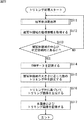
次に、図33のフローチャートを参照して、図32の制御部822を備える図31の画像処理装置811によるトリミング処理について説明する。
[Trimming]
Next, trimming processing by the
なお、図33のフローチャートのステップS811,S812,S817,S818の処理は、図23のフローチャートのステップS511,S512,S516,S517の処理と基本的に同様であるので、その説明は省略する。 Note that the processing in steps S811, S812, S817, and S818 in the flowchart in FIG. 33 is basically the same as the processing in steps S511, S512, S516, and S517 in the flowchart in FIG.
ステップS813において、顔検出部821は、入力画像において、被写体追尾部55による被写体追尾処理によって検出された被写体としての人物の被写体領域から顔を検出する。さらに、顔検出部821は、検出した被写体の顔から、顔の表情を検出し、顔の表情を表す情報を制御部822に供給する。
In step S813, the
ステップS814において、条件判定部831は、顔検出部821からの顔の表情を表す情報に基づいて、被写体の顔の表情が笑顔であるか否かを判定する。
In step S814, the
具体的には、条件判定部831は、顔検出部821から1フレーム毎に供給されてくる顔の表情を表す情報を監視し、入力画像において、図34の左側に示されるように、被写体枠(被写体領域)Hに含まれる顔領域Fにおける顔の表情が、図34の右側に示されるように、笑顔になったか否かを判定する。
Specifically, the
ステップS814において、顔の表情が笑顔になっていないと判定された場合、処理はステップS811に戻り、顔の表情が笑顔になったフレームについての座標情報が被写体追尾部55から供給されるまで、ステップS811乃至S814の処理が繰り返される。
If it is determined in step S814 that the facial expression is not smiling, the process returns to step S811 until coordinate information about the frame in which the facial expression is smiling is supplied from the
一方、ステップS814において、顔の表情が笑顔になったと判定された場合、すなわち、被写体追尾部55から、顔の表情が笑顔になったフレームについての座標情報が供給された場合、条件判定部831は、イメージャ32に、撮像を指示する情報を供給する。また、条件判定部831は、顔の表情が笑顔になった旨の情報をRAWデータ記録制御部533およびトリミング枠設定部832に供給する。
On the other hand, if it is determined in step S814 that the facial expression is smiling, that is, if coordinate information is supplied from the
このように、被写体である人物の顔の表情が笑顔になったときにシャッタされるので、好適な表情の被写体の撮像画像を得ることができる。 In this way, since the shutter is taken when the facial expression of the person who is the subject is smiling, a captured image of the subject with a suitable facial expression can be obtained.
ステップS815において、RAWデータ記録制御部533は、条件判定部831から、顔の表情が笑顔になった旨の情報が供給されると、メモリコントローラ58を制御し、シャッタフレームについてのRAWデータをDRAM40に記録させる。
In step S815, when the information indicating that the facial expression is smiling is supplied from the
ステップS816において、トリミング枠設定部832は、座標情報取得部531からの座標情報に基づいて、シャッタフレームにおいて、座標情報取得部531からの座標情報で表される被写体領域の位置に応じた数のトリミング枠を、被写体領域を含むように設定する。
In step S816, the trimming
ここで、トリミング枠設定部832は、被写体領域の中心位置の、撮像画像の中心位置からの距離に応じた数のトリミング枠を設定する。具体的には、被写体領域の中心位置が撮像画像の中心位置から大きく離れている場合、より少ない数のトリミング枠を設定する。
Here, the trimming
このようにして、撮像画像において、被写体領域の位置に応じた数のトリミング枠が設定される。トリミング枠設定部832は、設定した複数のトリミング枠を表す情報をトリミング画像生成制御部535に供給する。
In this way, the number of trimming frames corresponding to the position of the subject area is set in the captured image. The trimming
以上の処理によれば、被写体である人物の表情に応じて撮像された撮像画像において、被写体領域を含む、被写体領域の位置に応じた数のトリミング枠が設定されて、複数のトリミング画像が生成される。これにより、ユーザがシャッタ操作を行うことなく、撮影後の面倒な操作や、撮影時の高度な技術を必要とせずに、好適なトリミング画像を提供することが可能となる。 According to the above processing, in the captured image captured according to the facial expression of the person who is the subject, the number of trimming frames including the subject area is set according to the position of the subject area, and a plurality of trimmed images are generated. Is done. Accordingly, it is possible to provide a suitable trimmed image without performing a shutter operation by the user and without requiring a troublesome operation after shooting and a high level technique at the time of shooting.
特に、被写体領域の中心位置が撮像画像の中心位置から大きく離れている場合には、より少ない数のトリミング枠が設定されるので、被写体である人物の顔の表情が笑顔であっても、被写体の位置が決してよくない場合にはトリミング画像の生成を抑えることができ、記録メディア39の容量を削減することができる。
In particular, when the center position of the subject area is far away from the center position of the captured image, a smaller number of trimming frames are set, so even if the facial expression of the person who is the subject is a smile, the subject When the position of the recording medium is not good, the generation of the trimmed image can be suppressed, and the capacity of the
なお、以上においては、本画像とトリミング画像とを生成して記録する構成について説明してきたが、本画像に、トリミング枠を表すトリミング枠情報をメタデータとして付加して、本画像のみを記録するようにしてもよい。これにより、パーソナルコンピュータ等の情報処理装置において本画像を編集するときに、トリミング枠情報を含むメタデータに基づいて、トリミング画像を生成することができるようになる。 In the above description, the configuration for generating and recording the main image and the trimming image has been described. However, trimming frame information representing the trimming frame is added to the main image as metadata, and only the main image is recorded. You may do it. As a result, when the main image is edited by an information processing apparatus such as a personal computer, a trimmed image can be generated based on the metadata including the trimming frame information.
また、以上においては、シャッタのトリガとして、被写体追尾部55により追尾された被写体の状態を用いるようにしたが、被写体追尾部55に限らず、フレーム毎に、被写体の位置や動き等を検出する検出器の出力を、シャッタのトリガとするようにしてもよい。
In the above description, the state of the subject tracked by the
上述した一連の処理は、ハードウェアにより実行することもできるし、ソフトウェアにより実行することもできる。一連の処理をソフトウェアにより実行する場合には、そのソフトウェアを構成するプログラムが、専用のハードウェアに組み込まれているコンピュータ、または、各種のプログラムをインストールすることで、各種の機能を実行することが可能な、例えば汎用のパーソナルコンピュータ等に、プログラム記録媒体からインストールされる。 The series of processes described above can be executed by hardware or can be executed by software. When a series of processing is executed by software, a program constituting the software may execute various functions by installing a computer incorporated in dedicated hardware or various programs. For example, it is installed from a program recording medium in a general-purpose personal computer or the like.
図35は、上述した一連の処理をプログラムにより実行するコンピュータのハードウェアの構成例を示すブロック図である。 FIG. 35 is a block diagram illustrating a hardware configuration example of a computer that executes the above-described series of processing by a program.
コンピュータにおいて、CPU(Central Processing Unit)901,ROM(Read Only Memory)902,RAM(Random Access Memory)903は、バス904により相互に接続されている。
In a computer, a CPU (Central Processing Unit) 901, a ROM (Read Only Memory) 902, and a RAM (Random Access Memory) 903 are connected to each other by a
バス904には、さらに、入出力インタフェース905が接続されている。入出力インタフェース905には、キーボード、マウス、マイクロホン等よりなる入力部906、ディスプレイ、スピーカ等よりなる出力部907、ハードディスクや不揮発性のメモリ等よりなる記憶部908、ネットワークインタフェース等よりなる通信部909、磁気ディスク、光ディスク、光磁気ディスク、或いは半導体メモリ等のリムーバブルメディア911を駆動するドライブ910が接続されている。
An input /
以上のように構成されるコンピュータでは、CPU901が、例えば、記憶部908に記憶されているプログラムを、入出力インタフェース905およびバス904を介して、RAM903にロードして実行することにより、上述した一連の処理が行われる。
In the computer configured as described above, the
コンピュータ(CPU901)が実行するプログラムは、例えば、磁気ディスク(フレキシブルディスクを含む)、光ディスク(CD-ROM(Compact Disc-Read Only Memory),DVD(Digital Versatile Disc)等)、光磁気ディスク、もしくは半導体メモリ等よりなるパッケージメディアであるリムーバブルメディア911に記録して、あるいは、ローカルエリアネットワーク、インターネット、デジタル衛星放送といった、有線または無線の伝送媒体を介して提供される。
The program executed by the computer (CPU 901) is, for example, a magnetic disk (including a flexible disk), an optical disk (CD-ROM (Compact Disc-Read Only Memory), DVD (Digital Versatile Disc), etc.), a magneto-optical disk, or a semiconductor. The program is recorded on a
そして、プログラムは、リムーバブルメディア911をドライブ910に装着することにより、入出力インタフェース905を介して、記憶部908にインストールすることができる。また、プログラムは、有線または無線の伝送媒体を介して、通信部909で受信し、記憶部908にインストールすることができる。その他、プログラムは、ROM902や記憶部908に、あらかじめインストールしておくことができる。
The program can be installed in the
なお、コンピュータが実行するプログラムは、本明細書で説明する順序に沿って時系列に処理が行われるプログラムであっても良いし、並列に、あるいは呼び出しが行われたとき等の必要なタイミングで処理が行われるプログラムであっても良い。 The program executed by the computer may be a program that is processed in time series in the order described in this specification, or in parallel or at a necessary timing such as when a call is made. It may be a program for processing.
また、本発明の実施の形態は、上述した実施の形態に限定されるものではなく、本発明の要旨を逸脱しない範囲において種々の変更が可能である。 The embodiments of the present invention are not limited to the above-described embodiments, and various modifications can be made without departing from the scope of the present invention.
11 画像処理装置, 34 表示部, 35 制御部, 39 記録メディア, 40 DRAM, 55 被写体追尾部, 57 記録メディアインタフェース, 58 メモリコントローラ, 71 被写体マップ生成部, 72 被写体候補領域矩形化部, 73 被写体領域選択部, 74 重み係数算出部, 111 特徴量マップ生成部, 112 帯域特徴量マップ生成部, 113 帯域特徴量マップ合成部, 114 合成特徴量マップ合成部, 131 2値化処理部, 132 ラベリング処理部, 133 矩形領域座標算出部, 134 領域情報算出部, 151 領域情報比較部, 152 被写体領域決定部, 200 入力画像, 201 被写体マップ, 221,222 矩形領域, 231 被写体枠, 331 操作判定部, 332 座標情報取得部, 333 RAWデータ記録制御部, 334 トリミング枠設定部, 335 トリミング画像生成制御部, 336 画像記録制御部, 431 トリミング枠設定部, 811 画像処理装置, 822 制御部, 831 条件判定部, 832 トリミング枠設定部
DESCRIPTION OF
Claims (8)
前記トリミング枠設定手段により設定された複数の前記トリミング枠に基づいて、前記所定フレームの画像からの、複数のトリミング画像の生成を制御する生成制御手段と
を備え、
前記トリミング枠設定手段は、前記被写体領域の前記所定フレームの画像に占める大きさの割合に応じた数の前記トリミング枠を設定し、かつ、前記被写体から検出される前記被写体の状態が所定の条件を満たした場合に、前記被写体領域の位置に応じた数の前記トリミング枠を設定する
画像処理装置。 A trimming frame setting means for setting a plurality of trimming frames including a subject area which is an area of a subject of interest in an image of a predetermined frame;
Generation control means for controlling the generation of a plurality of trimmed images from the image of the predetermined frame based on the plurality of trimming frames set by the trimming frame setting means,
The trimming frame setting means sets the number of the trimming frames corresponding to the ratio of the size of the subject area to the image of the predetermined frame , and the state of the subject detected from the subject is a predetermined condition An image processing apparatus that sets the number of trimming frames corresponding to the position of the subject area when the above condition is satisfied .
請求項1に記載の画像処理装置。 The trimming frame setting means sets a smaller number of trimming frames when the size of the subject area is larger than the size of the image of the predetermined frame, and the size of the subject area is small. The image processing apparatus according to claim 1, wherein a larger number of the trimming frames are set.
前記所定フレームの画像において、前記被写体領域が前記所定フレームの画像の略中央にあるときに、前記撮像手段に、前記所定フレームの画像の撮像を指示する指示手段と、
前記指示手段の指示に基づいて、前記撮像手段により撮像された前記所定フレームの画像の記録を制御する記録制御手段とをさらに備える
請求項1に記載の画像処理装置。 Imaging means for imaging a subject;
An instruction means for instructing the imaging means to capture the image of the predetermined frame when the subject region is substantially at the center of the image of the predetermined frame in the image of the predetermined frame;
The image processing apparatus according to claim 1, further comprising: a recording control unit that controls recording of the image of the predetermined frame imaged by the imaging unit based on an instruction from the instruction unit.
請求項1に記載の画像処理装置。 The image processing apparatus according to claim 1, wherein the trimming frame setting unit sets the number of trimming frames corresponding to the size and position of the subject area in the image of the predetermined frame.
前記トリミング枠設定手段は、前記人物の顔の表情が前記所定の条件を満たした場合に、前記被写体領域の位置に応じた数の前記トリミング枠を設定する
請求項1に記載の画像処理装置。 When the subject is a person, the apparatus further comprises determination means for determining the facial expression of the person,
The image processing apparatus according to claim 1 , wherein the trimming frame setting unit sets the number of trimming frames according to the position of the subject area when the facial expression of the person satisfies the predetermined condition .
請求項1に記載の画像処理装置。 The trimming frame setting means sets a plurality of trimming frames in which the position of the subject region is a predetermined position in a predetermined composition in the trimmed image in the image of the predetermined frame. Image processing device.
前記トリミング枠設定手段により設定された複数の前記トリミング枠に基づいて、前記所定フレームの画像からの、複数のトリミング画像の生成を制御する生成制御手段とを備える画像処理装置の画像処理方法において、
前記トリミング枠設定手段が、前記被写体領域の前記所定フレームの画像に占める大きさの割合に応じた数の前記トリミング枠を設定し、かつ、前記被写体から検出される前記被写体の状態が所定の条件を満たした場合に、前記被写体領域の位置に応じた数の前記トリミング枠を設定し、
前記生成制御手段が、前記トリミング枠設定手段により設定された複数の前記トリミング枠に基づいて、前記所定フレームの画像からの、複数のトリミング画像の生成を制御する
ステップを含む画像処理方法。 A trimming frame setting means for setting a plurality of trimming frames including a subject area which is an area of a subject of interest in an image of a predetermined frame;
In an image processing method of an image processing apparatus, comprising: a generation control unit that controls generation of a plurality of trimmed images from an image of the predetermined frame based on the plurality of trimming frames set by the trimming frame setting unit.
The trimming frame setting means sets the number of the trimming frames according to the ratio of the size of the subject area to the image of the predetermined frame , and the state of the subject detected from the subject is a predetermined condition Is set , the number of the trimming frames corresponding to the position of the subject area is set ,
An image processing method including a step in which the generation control unit controls generation of a plurality of trimmed images from the image of the predetermined frame based on the plurality of trimming frames set by the trimming frame setting unit.
前記トリミング枠設定ステップの処理により設定された複数の前記トリミング枠に基づいて、前記所定フレームの画像からの、複数のトリミング画像の生成を制御する生成制御ステップと
を含む処理をコンピュータに実行させ、
前記トリミング枠設定ステップの処理においては、前記被写体領域の前記所定フレームの画像に占める大きさの割合に応じた数の前記トリミング枠が設定され、かつ、前記被写体から検出される前記被写体の状態が所定の条件を満たした場合に、前記被写体領域の位置に応じた数の前記トリミング枠が設定される
プログラム。 A trimming frame setting step for setting a plurality of trimming frames including a subject area that is an area of a subject of interest in an image of a predetermined frame;
Based on the plurality of trimming frames set by the processing of the trimming frame setting step, the computer executes a process including a generation control step for controlling generation of a plurality of trimmed images from the image of the predetermined frame,
In the trimming frame setting step, the number of the trimming frames corresponding to the ratio of the size of the subject area to the image of the predetermined frame is set , and the state of the subject detected from the subject is determined. A program in which the number of trimming frames corresponding to the position of the subject area is set when a predetermined condition is satisfied .
Priority Applications (4)
| Application Number | Priority Date | Filing Date | Title |
|---|---|---|---|
| JP2010079186A JP5803058B2 (en) | 2010-03-30 | 2010-03-30 | Image processing apparatus and method, and program |
| US13/023,866 US8681238B2 (en) | 2010-03-30 | 2011-02-09 | Image processing device, method and program |
| CN201110069738.XA CN102215336B (en) | 2010-03-30 | 2011-03-23 | Image processing equipment and method |
| US14/185,413 US9332196B2 (en) | 2010-03-30 | 2014-02-20 | Image processing device, method and program |
Applications Claiming Priority (1)
| Application Number | Priority Date | Filing Date | Title |
|---|---|---|---|
| JP2010079186A JP5803058B2 (en) | 2010-03-30 | 2010-03-30 | Image processing apparatus and method, and program |
Publications (3)
| Publication Number | Publication Date |
|---|---|
| JP2011211629A JP2011211629A (en) | 2011-10-20 |
| JP2011211629A5 JP2011211629A5 (en) | 2013-05-02 |
| JP5803058B2 true JP5803058B2 (en) | 2015-11-04 |
Family
ID=44709241
Family Applications (1)
| Application Number | Title | Priority Date | Filing Date |
|---|---|---|---|
| JP2010079186A Expired - Fee Related JP5803058B2 (en) | 2010-03-30 | 2010-03-30 | Image processing apparatus and method, and program |
Country Status (3)
| Country | Link |
|---|---|
| US (2) | US8681238B2 (en) |
| JP (1) | JP5803058B2 (en) |
| CN (1) | CN102215336B (en) |
Families Citing this family (6)
| Publication number | Priority date | Publication date | Assignee | Title |
|---|---|---|---|---|
| JP5565041B2 (en) | 2010-03-30 | 2014-08-06 | ソニー株式会社 | Image processing apparatus and method, and program |
| JP5882975B2 (en) | 2012-12-26 | 2016-03-09 | キヤノン株式会社 | Image processing apparatus, imaging apparatus, image processing method, and recording medium |
| KR101999137B1 (en) | 2013-01-03 | 2019-07-11 | 삼성전자주식회사 | Apparatus and method for processing an image in device having an camera |
| US8994838B2 (en) * | 2013-04-16 | 2015-03-31 | Nokia Corporation | Motion adaptive cropping for video stabilization |
| CN105357436B (en) * | 2015-11-03 | 2018-07-03 | 广东欧珀移动通信有限公司 | For the image cropping method and system in image taking |
| CN107295285B (en) * | 2017-08-11 | 2018-07-27 | 腾讯科技(深圳)有限公司 | Processing method, processing unit and the storage medium of video data |
Family Cites Families (14)
| Publication number | Priority date | Publication date | Assignee | Title |
|---|---|---|---|---|
| JPH05100288A (en) * | 1991-10-11 | 1993-04-23 | Minolta Camera Co Ltd | Camera with electric view finder |
| US6930718B2 (en) * | 2001-07-17 | 2005-08-16 | Eastman Kodak Company | Revised recapture camera and method |
| EP1443385A1 (en) * | 2001-10-24 | 2004-08-04 | Sony Corporation | Image information displaying device |
| CN1241386C (en) * | 2002-02-21 | 2006-02-08 | 佳能株式会社 | Digital camera, image processing device, image processing method, image processing system and program |
| JP4244577B2 (en) * | 2002-07-12 | 2009-03-25 | トヨタ自動車株式会社 | Fuel injection control device for in-cylinder internal combustion engine |
| JP2006018246A (en) * | 2004-06-03 | 2006-01-19 | Canon Inc | Imaging apparatus and imaging method |
| US8525892B2 (en) * | 2005-04-21 | 2013-09-03 | Canon Kabushiki Kaisha | Imaging apparatus and control method therefor |
| JP4800104B2 (en) * | 2005-06-13 | 2011-10-26 | 富士フイルム株式会社 | Album creating apparatus, album creating method, and program |
| JP4929631B2 (en) * | 2005-07-08 | 2012-05-09 | カシオ計算機株式会社 | Image generating apparatus and image generating method |
| JP2007272685A (en) * | 2006-03-31 | 2007-10-18 | Fujifilm Corp | Automatic trimming method, device and program |
| JP2007295203A (en) * | 2006-04-24 | 2007-11-08 | Olympus Imaging Corp | Image editing apparatus |
| JP2007316957A (en) * | 2006-05-26 | 2007-12-06 | Fujifilm Corp | Image trimming device, image trimming method and program |
| KR100811796B1 (en) * | 2007-03-30 | 2008-03-10 | 삼성전자주식회사 | Mobile terminal and method for displaying image using focus information thereof |
| JP5398408B2 (en) * | 2009-08-07 | 2014-01-29 | オリンパスイメージング株式会社 | CAMERA, CAMERA CONTROL METHOD, DISPLAY CONTROL DEVICE, AND DISPLAY CONTROL METHOD |
-
2010
- 2010-03-30 JP JP2010079186A patent/JP5803058B2/en not_active Expired - Fee Related
-
2011
- 2011-02-09 US US13/023,866 patent/US8681238B2/en not_active Expired - Fee Related
- 2011-03-23 CN CN201110069738.XA patent/CN102215336B/en not_active Expired - Fee Related
-
2014
- 2014-02-20 US US14/185,413 patent/US9332196B2/en active Active
Also Published As
| Publication number | Publication date |
|---|---|
| CN102215336A (en) | 2011-10-12 |
| US20110242347A1 (en) | 2011-10-06 |
| US8681238B2 (en) | 2014-03-25 |
| US9332196B2 (en) | 2016-05-03 |
| JP2011211629A (en) | 2011-10-20 |
| US20140218568A1 (en) | 2014-08-07 |
| CN102215336B (en) | 2015-10-28 |
Similar Documents
| Publication | Publication Date | Title |
|---|---|---|
| JP5577793B2 (en) | Image processing apparatus and method, and program | |
| JP5565041B2 (en) | Image processing apparatus and method, and program | |
| US8077214B2 (en) | Signal processing apparatus, signal processing method, program and recording medium | |
| US8682104B2 (en) | Image synthesizing apparatus, image synthesizing method, and image synthesizing program | |
| KR101603791B1 (en) | Method for fabricating a panorama | |
| JP5803058B2 (en) | Image processing apparatus and method, and program | |
| US20110188758A1 (en) | Image processing device and method, and program therefor | |
| JP2011035636A (en) | Image processor and method | |
| US9020269B2 (en) | Image processing device, image processing method, and recording medium | |
| JP5429564B2 (en) | Image processing apparatus and method, and program | |
| JP2011146826A (en) | Unit and method for processing image, and program | |
| JP2011146827A (en) | Unit and method for processing image, and program | |
| KR101603876B1 (en) | Method for fabricating a panorama | |
| JP5871175B2 (en) | Region extraction device, imaging device, and region extraction program | |
| JP6729583B2 (en) | Image processing apparatus and method |
Legal Events
| Date | Code | Title | Description |
|---|---|---|---|
| A521 | Request for written amendment filed |
Free format text: JAPANESE INTERMEDIATE CODE: A523 Effective date: 20130315 |
|
| A621 | Written request for application examination |
Free format text: JAPANESE INTERMEDIATE CODE: A621 Effective date: 20130315 |
|
| A977 | Report on retrieval |
Free format text: JAPANESE INTERMEDIATE CODE: A971007 Effective date: 20140114 |
|
| A131 | Notification of reasons for refusal |
Free format text: JAPANESE INTERMEDIATE CODE: A131 Effective date: 20140206 |
|
| A521 | Request for written amendment filed |
Free format text: JAPANESE INTERMEDIATE CODE: A523 Effective date: 20140403 |
|
| A131 | Notification of reasons for refusal |
Free format text: JAPANESE INTERMEDIATE CODE: A131 Effective date: 20141202 |
|
| A521 | Request for written amendment filed |
Free format text: JAPANESE INTERMEDIATE CODE: A523 Effective date: 20150130 |
|
| TRDD | Decision of grant or rejection written | ||
| A01 | Written decision to grant a patent or to grant a registration (utility model) |
Free format text: JAPANESE INTERMEDIATE CODE: A01 Effective date: 20150804 |
|
| A61 | First payment of annual fees (during grant procedure) |
Free format text: JAPANESE INTERMEDIATE CODE: A61 Effective date: 20150817 |
|
| R151 | Written notification of patent or utility model registration |
Ref document number: 5803058 Country of ref document: JP Free format text: JAPANESE INTERMEDIATE CODE: R151 |
|
| R250 | Receipt of annual fees |
Free format text: JAPANESE INTERMEDIATE CODE: R250 |
|
| R250 | Receipt of annual fees |
Free format text: JAPANESE INTERMEDIATE CODE: R250 |
|
| R250 | Receipt of annual fees |
Free format text: JAPANESE INTERMEDIATE CODE: R250 |
|
| LAPS | Cancellation because of no payment of annual fees |