JP6729583B2 - Image processing apparatus and method - Google Patents
Image processing apparatus and method Download PDFInfo
- Publication number
- JP6729583B2 JP6729583B2 JP2017527170A JP2017527170A JP6729583B2 JP 6729583 B2 JP6729583 B2 JP 6729583B2 JP 2017527170 A JP2017527170 A JP 2017527170A JP 2017527170 A JP2017527170 A JP 2017527170A JP 6729583 B2 JP6729583 B2 JP 6729583B2
- Authority
- JP
- Japan
- Prior art keywords
- image
- image processing
- designated
- focus
- subject
- Prior art date
- Legal status (The legal status is an assumption and is not a legal conclusion. Google has not performed a legal analysis and makes no representation as to the accuracy of the status listed.)
- Active
Links
Images


Classifications
-
- G—PHYSICS
- G02—OPTICS
- G02B—OPTICAL ELEMENTS, SYSTEMS OR APPARATUS
- G02B7/00—Mountings, adjusting means, or light-tight connections, for optical elements
- G02B7/28—Systems for automatic generation of focusing signals
-
- H—ELECTRICITY
- H04—ELECTRIC COMMUNICATION TECHNIQUE
- H04N—PICTORIAL COMMUNICATION, e.g. TELEVISION
- H04N23/00—Cameras or camera modules comprising electronic image sensors; Control thereof
- H04N23/60—Control of cameras or camera modules
- H04N23/67—Focus control based on electronic image sensor signals
- H04N23/675—Focus control based on electronic image sensor signals comprising setting of focusing regions
-
- H—ELECTRICITY
- H04—ELECTRIC COMMUNICATION TECHNIQUE
- H04N—PICTORIAL COMMUNICATION, e.g. TELEVISION
- H04N23/00—Cameras or camera modules comprising electronic image sensors; Control thereof
- H04N23/60—Control of cameras or camera modules
- H04N23/61—Control of cameras or camera modules based on recognised objects
-
- H—ELECTRICITY
- H04—ELECTRIC COMMUNICATION TECHNIQUE
- H04N—PICTORIAL COMMUNICATION, e.g. TELEVISION
- H04N23/00—Cameras or camera modules comprising electronic image sensors; Control thereof
- H04N23/60—Control of cameras or camera modules
- H04N23/62—Control of parameters via user interfaces
-
- H—ELECTRICITY
- H04—ELECTRIC COMMUNICATION TECHNIQUE
- H04N—PICTORIAL COMMUNICATION, e.g. TELEVISION
- H04N23/00—Cameras or camera modules comprising electronic image sensors; Control thereof
- H04N23/60—Control of cameras or camera modules
- H04N23/63—Control of cameras or camera modules by using electronic viewfinders
- H04N23/631—Graphical user interfaces [GUI] specially adapted for controlling image capture or setting capture parameters
- H04N23/632—Graphical user interfaces [GUI] specially adapted for controlling image capture or setting capture parameters for displaying or modifying preview images prior to image capturing, e.g. variety of image resolutions or capturing parameters
-
- H—ELECTRICITY
- H04—ELECTRIC COMMUNICATION TECHNIQUE
- H04N—PICTORIAL COMMUNICATION, e.g. TELEVISION
- H04N23/00—Cameras or camera modules comprising electronic image sensors; Control thereof
- H04N23/60—Control of cameras or camera modules
- H04N23/63—Control of cameras or camera modules by using electronic viewfinders
- H04N23/633—Control of cameras or camera modules by using electronic viewfinders for displaying additional information relating to control or operation of the camera
- H04N23/635—Region indicators; Field of view indicators
-
- H—ELECTRICITY
- H04—ELECTRIC COMMUNICATION TECHNIQUE
- H04N—PICTORIAL COMMUNICATION, e.g. TELEVISION
- H04N5/00—Details of television systems
- H04N5/222—Studio circuitry; Studio devices; Studio equipment
- H04N5/2224—Studio circuitry; Studio devices; Studio equipment related to virtual studio applications
- H04N5/2226—Determination of depth image, e.g. for foreground/background separation
-
- H—ELECTRICITY
- H04—ELECTRIC COMMUNICATION TECHNIQUE
- H04N—PICTORIAL COMMUNICATION, e.g. TELEVISION
- H04N5/00—Details of television systems
- H04N5/222—Studio circuitry; Studio devices; Studio equipment
- H04N5/262—Studio circuits, e.g. for mixing, switching-over, change of character of image, other special effects ; Cameras specially adapted for the electronic generation of special effects
- H04N5/272—Means for inserting a foreground image in a background image, i.e. inlay, outlay
Description
本開示は、画像処理装置および方法に関し、特に、オートフォーカスの際に、主要被写体領域を正しく求めることができるようにした画像処理装置および方法に関する。 The present disclosure relates to an image processing apparatus and method, and more particularly to an image processing apparatus and method capable of accurately obtaining a main subject area during autofocus.
カメラのフォーカスを自動で合わせる(オートフォーカス(AF)機能)技術について、合焦評価値に基づいてフォーカスブラケット撮影を行う技術がある(特許文献1参照)。 As a technique for automatically adjusting the focus of a camera (auto focus (AF) function), there is a technique for performing focus bracket photographing based on a focus evaluation value (see Patent Document 1).
しかしながら、より多様な撮像条件においても、撮影者の意図する被写体に正しくフォーカスを合わせる技術が望まれている。 However, there is a demand for a technique for correctly focusing on a subject intended by a photographer even under various imaging conditions.
本開示は、このような状況に鑑みてなされたものであり、より正しく、オートフォーカスができるようにするものである。 The present disclosure has been made in view of such a situation, and is for enabling more accurate autofocus.
本開示の一側面の画像処理装置は、画像内の複数の被写体についての領域を示す被写体領域情報と前記画像内の合焦指定位置を示す合焦指定位置情報に基づいて、合焦に関する制御を行う制御部を備え、前記画像処理部は、前記合焦に関する処理として、前記合焦指定位置が背景の領域であった場合、前記合焦指定位置を、前記複数の被写体のうちの主要被写体の領域に修正する。 An image processing apparatus according to an aspect of the present disclosure performs control regarding focusing based on subject area information indicating areas of a plurality of subjects in an image and focus designated position information indicating a designated focus position in the image. As a process relating to focusing, the image processing unit includes a control unit that performs, when the designated focus position is a background area, sets the designated focus position to a main subject of the plurality of subjects. Correct to the area.
前記複数の被写体は、主要被写体と背景を含むことができる。 The plurality of subjects may include a main subject and a background.
前記複数の被写体は、少なくとも類似する2つ以上の被写体を含むことができる。 The plurality of subjects may include at least two similar subjects.
前記画像処理部は、前記合焦に関する処理として、背景の領域を推定する処理を行うことができる。 The image processing unit can perform a process of estimating a background area as the process related to the focusing.
前記画像処理部は、前記合焦に関する処理として、前記合焦指定位置を特定することができる。 The image processing unit can specify the designated focus position as the processing relating to the focus.
前記画像処理部は、前記合焦に関する処理として、前記合焦指定位置の領域を囲む被写体枠を生成させることができる。 The image processing unit may generate a subject frame surrounding the area at the designated focus position as the processing relating to the focus.
色の境界に基づいて、入力画像を複数の被写体についての領域に分割する領域分割部をさらに備えることができる。 An area dividing unit that divides the input image into areas for a plurality of subjects based on color boundaries can be further included.
前記被写体領域情報は、色の境界で分割された前記画像内の複数の被写体についての領域を示す情報である。 The subject area information is information indicating areas of a plurality of subjects in the image divided by color boundaries.
前記合焦指定位置情報は、前記画像内において選択された局所フォーカスエリアに含まれる点の位置を示す情報である。 The designated focus position information is information indicating the position of a point included in the local focus area selected in the image.
本開示の一側面の画像処理方法は、画像内の複数の被写体についての領域を示す被写体領域情報と前記画像内の合焦指定位置を示す合焦指定位置情報に基づいて、合焦に関する制御を行い、前記合焦に関する処理として、前記合焦指定位置が背景の領域であった場合、前記合焦指定位置を、前記複数の被写体のうちの主要被写体の領域に修正する。 An image processing method according to one aspect of the present disclosure performs control relating to focusing based on subject area information indicating areas of a plurality of subjects in an image and focus designated position information indicating a designated focus position in the image. there line, as a process related to focus the case, the case focusing the specified position is a region of the background, the focus designated position, corrects the area of the main subject of the plurality of subjects.
本開示の一側面においては、画像内の複数の被写体についての領域を示す被写体領域情報と前記画像内の合焦指定位置を示す合焦指定位置情報に基づいて、合焦に関する制御が行われる。そして、前記合焦に関する処理として、前記合焦指定位置が背景の領域であった場合、前記合焦指定位置が、前記複数の被写体のうちの主要被写体の領域に修正される。 In one aspect of the present disclosure, based on the focusing focusing designated positional information indicating a designated position in said image and object area information indicating the area for a plurality of objects in an image, the control relates focusing cracking line. Then, as the processing relating to the focusing, when the designated focus position is a background area, the designated focus position is corrected to the area of the main subject of the plurality of subjects.
本開示の一側面によれば、特に、オートフォーカスの際に、主要被写体領域を正しく求めることができる。 According to the embodiments of the present disclosure, it is possible to correctly obtain the main subject area, particularly during autofocus.
なお、本明細書に記載された効果は、あくまで例示であり、本技術の効果は、本明細書に記載された効果に限定されるものではなく、付加的な効果があってもよい。 Note that the effects described in the present specification are merely examples, and the effects of the present technology are not limited to the effects described in the present specification, and may have additional effects.
以下、本開示を実施するための形態(以下実施の形態とする)について説明する。 Hereinafter, modes for implementing the present disclosure (hereinafter referred to as embodiments) will be described.
[本技術の撮像装置]
図1は、本技術を適用した撮像装置の構成例を示すブロック図である。[Imaging device of the present technology]
FIG. 1 is a block diagram showing a configuration example of an imaging device to which the present technology is applied.
図1の撮像装置10は、レンズユニット100、撮像素子101、画像処理部102、制御部103、表示部104、メモリ105、記録デバイス106、操作部107、センサ部108、およびバス109を含むように構成されている。
The
レンズユニット100は、被写体の光画像を集光する。レンズユニット100は、制御部103からの指示に従い、適切な画像を得られるように、フォーカスレンズ、絞りなどを調整する機構を有する。
The
撮像素子101は、レンズユニット100で集光された光画像を光電変換して電気信号に変換する。具体的には、撮像素子101は、CCD(Charge Coupled Device)イメージセンサやCMOS(Complementary Metal Oxide Semiconductor)イメージセンサなどにより実現される。
The
画像処理部102、制御部103、表示部104、メモリ105、記録デバイス106、操作部107、およびセンサ部108は、バス109を介して相互に接続されている。
The
画像処理部102は、撮像素子101からの電気信号をサンプリングするサンプリング回路、アナログ信号をデジタル信号に変換するA/D変換回路、デジタル信号に所定の画像処理を施す画像処理回路などから構成される。画像処理部102は、専用のハードウェア回路のみではなく、CPU(Central Processing Unit)やDSP(Digital Signal Processor)を備え、柔軟な画像処理に対応するためにソフトウェア処理を行うことができる。
The
特に、画像処理部102は、画像を領域分割し、制御部103からの局所フォーカスエリアの情報に基づいて、合焦に関する処理(背景推定、開始指示点修正、領域結合、被写体枠生成などの処理)を行う。なお、画像処理部102により実行される処理の詳細については後述する。
In particular, the
制御部103は、CPU(Central Processing Unit)及び制御プログラムからなり画像処理装置の各部の制御を行う。制御プログラム自体は実際にはメモリ105に格納され、CPUによって実行される。特に、制御部103は、撮像された画像情報から局所フォーカスエリアを選択し、選択した局所フォーカスエリアにおけるフォーカス対象位置(奥行き)と、レンズユニット100の合焦位置(奥行き)に基づいて、レンズユニット100のフォーカスレンズを駆動する。また、制御部103は、選択した局所フォーカスエリアを示す情報である合焦指定位置情報を画像処理部102に供給する。
The
表示部104は、画像処理部102によって処理された、メモリ105に格納されている画像信号をアナログ化するD/A変換回路と、アナログ化された画像信号を後段の表示装置に適合する形式のビデオ信号にエンコードするビデオエンコーダと、入力されるビデオ信号に対応する画像を表示する表示装置とから構成される。表示装置は、例えば、LCD(Liquid Crystal Display)等により実現され、ファインダとしての機能も有する。
The
メモリ105は、DRAM(Dynamic Random Access Memory)などの半導体メモリから構成され、画像処理部102で処理された画像データ、制御部103における制御プログラム及び各種データなどが一時記録される。
The
記録デバイス106は、FLASHメモリなどの半導体メモリ、磁気ディスク、光ディスク、光磁気ディスクなどで構成される。撮影時には画像処理部102でJPEG形式にエンコードされ、メモリ105に格納されたJPEG画像データを記録メディアに記録する。再生時には、記録メディアに保存されたJPEG画像データをメモリ105に読み込み、画像処理部102でデコード処理を行う。
The
操作部107は、シャッタボタンなどのハードウェアキー、操作ダイアル、タッチパネルなどの入力デバイスで構成され、撮影者の入力操作を検出し、制御部103の制御によって画像処理装置の動作が決定される。
The
センサ部108は、ジャイロセンサ、加速度センサ、地磁気センサ、GPS(Global Positioning System)センサなどで構成され、各種情報の検出を行う。これらの情報は、撮影された画像データに対して、メタデータとして付加されるほか、各種画像処理、制御処理にも利用される。
The
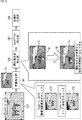
図2は、画像処理部102により実行される機能ブロックの構成例を示すブロック図である。
FIG. 2 is a block diagram showing a configuration example of functional blocks executed by the
図2に示される機能ブロックは、SuperPixel生成部121および被写体枠生成部122を含むように構成されている。図2の例における指と星のアイコンは、制御部103からの局所フォーカスエリアを示す合焦指定位置情報として入力される、局所フォーカスエリアに含まれる初期点(開始指示点)Sを表している。初期点とは、例えば、局所フォーカスエリアの略中心の点などからなる。なお、局所フォーカスエリアは、フォーカスポイントであってもよい。したがって、合焦指定位置情報は、局所フォーカスエリアの位置情報であってもよいし、その初期点の位置情報であってもよい。
The functional block shown in FIG. 2 is configured to include a
SuperPixel生成部121には、撮像素子101からの入力画像131が入力される。SuperPixel生成部121は、SuperPixel生成処理を行う。すなわち、SuperPixel生成部121は、SuperPixel生成技術を利用して、入力される入力画像131を色の境界で明示的に領域を分割し、領域分割された中間処理画像(SuperPixel画像)132を生成する。SuperPixel生成部121は、生成された中間処理画像132を被写体枠生成部122に出力する。
The
ここで、一般的に、被写体の境界では、色が異なることが多い。したがって、色で画素(ピクセル)をグルーピングするSuperPixel生成処理により生成された中間処理画像132において、主要被写体についての色の領域は、主要被写体についての色の類似色の領域とは、異なる被写体の領域とすることができる。すなわち、中間処理画像132は、SuperPixel生成処理により複数の被写体についての領域に分割されており、複数の被写体についての領域を示す被写体領域情報を有しているといえる。
Here, in general, the colors of the boundaries of the subject are often different. Therefore, in the intermediate processed
被写体枠生成部122には、制御部103から、局所フォーカスエリアに含まれる初期点(開始指示点)Sを示す合焦指定位置情報が入力される。被写体枠生成部122は、被写体領域情報を有する中間処理画像132を入力し、開始指示点Sを示す合焦指定位置情報と被写体領域情報に基づいて、合焦に関する処理(背景推定、開始指示点修正、領域結合、被写体枠生成などの処理)を行い、被写体枠Fが示される画像(被写体枠画像と称する)133を、例えば、表示部104に出力する。これに対応して、表示部104は、被写体枠Fが示される画像133を表示する。
Focusing designated position information indicating an initial point (start instruction point) S included in the local focus area is input to the subject
また、被写体枠生成部122は、修正された開始指示点の情報、あるいは、修正が必要なかった開始指示点の情報を、合焦指定位置情報として、制御部103に供給するようにしてもよい。その際、制御部103は、被写体枠生成部122からの合焦指定位置情報に基づくフォーカス対象位置(奥行き)により、レンズユニット100のフォーカスレンズを駆動する。
Further, the subject
図3は、被写体枠生成部の構成例を示すブロック図である。 FIG. 3 is a block diagram showing a configuration example of the subject frame generation unit.
図3の例において、被写体枠生成部122は、背景推定部141、開始指示点修正部142、SuperPixel結合部143、および候補枠生成部144により構成される。
In the example of FIG. 3, the subject
上述したように、背景推定画像151においては、複数の被写体の領域に分割されている。複数の被写体は、類似する2つ以上の被写体を含んでいる場合がある。また、複数の被写体は、フォーカス対象の被写体である主要被写体と背景を含む。背景推定部141は、中間処理画像132の複数の被写体の領域から、背景領域を推定し、背景領域が推定された画像である背景推定画像151(チェックのハッチ部分が背景部分)を、開始指示点修正部142に供給する。
As described above, the background estimated
開始点指示修正部142は、背景推定画像151において、開始指示点Sが位置する領域を特定し、特定した領域が背景領域であるならば、その開始指示点Sの位置を被写体信頼度において、主要被写体上に修正する。開始点指示修正部142は、開始指示点修正の終了した画像である開始指示点修正画像152を、Superpixel結合部143に供給する。
The start point
SuperPixel結合部143は、色距離や空間距離の近いSuperPixel同士を結合させ、SuperPixelが結合された画像を、候補枠生成部144に供給する。候補枠生成部144は、開始指示点Sが位置する、すなわち、主要被写体のSuperPixelが含まれる領域を囲む候補枠を生成し、被写体枠Fとして出力する。
The
図4は、SuperPixel生成部の処理について説明する図である。 FIG. 4 is a diagram illustrating processing of the SuperPixel generation unit.
SuperPixel生成部121は、入力画像131に対して、閾値を用いて、似たような色をグルーピングすることで、SuperPixel(画素群)を生成し、複数のSuperPixelが生成された画像、すなわち、領域分割された中間処理画像132を被写体生成部122に出力する。
The
図5は、被写体枠生成部の処理について説明する図である。 FIG. 5 is a diagram illustrating a process of the subject frame generation unit.
背景推定部141は、中間処理画像132において、SuperPixelの画像端画素数をチェックし、SuperPixelのサイズ・形状をチェックすることで、複数の被写体領域から、背景領域を推定し、背景が推定された画像である背景推定画像151を開始指示点修正部142に出力する。
The
開始指示点修正部142は、背景推定画像151において開始指示点Sが位置する領域が背景である場合、SuperPixel毎に、被写体である信頼度の高さを表す被写体信頼度を求め、求めた被写体信頼度に応じて開始指示点Sの修正を行う。
When the region in which the start designated point S is located in the background estimated
SuperPixel結合部143は、必要に応じて開始指示点Sの修正が行われた背景推定画像151において、色距離や空間距離の近いSuperPixel同士を結合させ、SuperPixelが結合された画像を、候補枠生成部144に供給する。
The
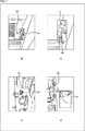
図6は、開始指示点の修正について説明する図である。 FIG. 6 is a diagram illustrating correction of the start instruction point.
図6に示されるように、開始指示点修正部142は、開始指示点S(図中星マーク)が背景と推定されたSuperPixelにあるとき、背景以外のSuperPixelに開始指示点Sをジャンプさせて修正する。
As shown in FIG. 6, when the designated start point S (star mark in the figure) is in the SuperPixel estimated to be the background, the designated start
例えば、背景推定画像151Aにおいては、背景(チェックのハッチ)と推定されたSuperPixelに開始指示点Sが存在するため、背景推定画像151B乃至151Dに示されるように、背景以外のSuperPixel(1,2,3)に移動させる。この移動は、次に説明される被写体信頼度に応じてなされる。
For example, in the background estimated
図7は、修正先の被写体信頼度について説明する図である。図7の例においては、Sが開始指示点を示し、修正先が被写体枠Fで示されている。なお、図7のAにおいては、中央の犬とお墓以外は、背景領域とされている。図7のBにおいては、中央の犬と犬の上にある窓の柵以外は、背景領域とされている。図7のCにおいては、犬と車以外は、背景領域とされている。図7のDにおいては、犬以外は背景領域とされている。 FIG. 7 is a diagram illustrating the subject reliability of the correction destination. In the example of FIG. 7, S indicates the start instruction point and the correction target is indicated by the subject frame F. In addition, in FIG. 7A, the area other than the central dog and the grave is a background area. In FIG. 7B, the area other than the central dog and the window fence above the dog is the background area. In C of FIG. 7, the area other than the dog and the car is the background area. In D of FIG. 7, the area other than the dog is the background area.
開始指示点が背景領域のSuperPixel内部のときに、開始指示点修正部142は、修正先のSuperPixelを以下の観点から選択する。
A:図7のAに示されるように、開始指示点からの空間距離が近いSuperPixelを主要被写体信頼度が高いとみなす。
B:図7のBに示されるように、フォーカスエリア中央(ここでは画像中央)からの空間距離が近いSuperPixelを主要被写体信頼度が高いとみなす。
C:図7のCに示されるように、背景から色距離が離れたSuperPixelがよい。
C−1:開始指示点の存在するSuperPixel(背景とみなされた)から色距離が離れたSuper-pixelを主要被写体信頼度が高いとみなす。
C−2:背景領域の中で最大サイズのSuperPixelから色距離が離れたSuperPixelを主要被写体信頼度が高いとみなす。
D:図7のDに示されるように、大きな面積のSuper-pixelを主要被写体信頼度が高いとみなす。When the start designated point is inside the SuperPixel in the background area, the start designated
A: As shown in A of FIG. 7, a SuperPixel having a short spatial distance from the start instruction point is regarded as having high reliability of the main subject.
B: As shown in B of FIG. 7, a SuperPixel having a short spatial distance from the center of the focus area (here, the center of the image) is considered to have high reliability of the main subject.
C: As shown in C of FIG. 7, a Super Pixel having a color distance away from the background is preferable.
C-1: A Super-pixel having a color distance away from the Super Pixel (considered as the background) having the start instruction point is regarded as having high reliability of the main subject.
C-2: SuperPixel having a color distance from the maximum size SuperPixel in the background area is regarded as having high reliability of the main subject.
D: As shown in D of FIG. 7, the Super-pixel having a large area is considered to have high reliability of the main subject.
以上のうちの少なくともいずれか1つを基に、あるいは、それらの組み合わせを基に、修正先のSuperPixelが選択される。 The correction destination SuperPixel is selected based on at least one of the above or a combination thereof.
次に、図8のフローチャートを参照して、図1の撮像装置10の撮像処理について説明する。
Next, with reference to the flowchart of FIG. 8, the imaging process of the
撮像装置10の制御部103は、ステップS11において、操作部107を構成するシャッタボタンが半押しされるまで待機しており、シャッタボタンが半押しされたと判定した場合、処理は、ステップS12に進む。
In step S11, the
ステップS12において、画像処理部102および制御部103は、1番目のフレームに対する処理を行う。この処理は、局所フォーカスエリアに応じて被写体を捕捉する処理であり、図9を参照して後述される。
In step S12, the
ステップS13において、画像処理部102および制御部103は、2番目以降のフレームに対する処理を行う。この処理は、被写体を追尾する処理であり、図11を参照して後述される。
In step S13, the
ステップS12およびS13の処理により、被写体枠Fが表示され、シャッタボタンが深押しされるので、制御部103は、ステップS14において、撮像素子101を制御し、写真を撮像させる。撮像素子101は、レンズユニット100で集光された光画像を光電変換して電気信号に変換する。画像処理部102は、撮像素子101からの電気信号をサンプリングし、デジタルの画像データに変換し、所定の画像処理を行う。
By the processing of steps S12 and S13, the subject frame F is displayed and the shutter button is pressed deeply. Therefore, in step S14, the
ステップS15において、画像処理部102は、画像データを、メモリ105に保存する。
In step S15, the
次に、図9のフローチャートを参照して、図8のステップS12の1番目のフレームに対する処理について説明する。なお、図9の例においては、被写体の捕捉処理が行われる。 Next, the processing for the first frame in step S12 in FIG. 8 will be described with reference to the flowchart in FIG. In addition, in the example of FIG. 9, a subject capturing process is performed.
図8のステップS11において、シャッタボタンが半押しされた際、その情報が、操作部107から、制御部103と画像処理部102に入力される。また、撮像素子101より、そのときの入力画像131が制御部103と画像処理部102に入力される。
In step S11 of FIG. 8, when the shutter button is pressed halfway, the information is input from the
ステップS31において、制御部103は、入力画像131から局所フォーカスエリアを選択する。選択された局所フォーカスエリアを示す合焦指定位置情報は、被写体枠生成部122に供給される。
In step S31, the
ステップS32において、制御部103は、合焦指定位置情報に基づいて、局所フォーカスエリアにおけるフォーカス対象位置(奥行き)とレンズ合焦位置(奥行き)のズレを計算する。ステップS33において、制御部103は、ステップS32により計算されたズレに基づいて、レンズユニット100のフォーカスレンズを駆動する。
In step S32, the
一方、ステップS34において、SuperPixel生成部121は、入力画像131から、SuperPixel生成技術を利用して、入力される入力画像131を色の境界で明示的に領域を分割し、(複数の被写体について)領域分割された中間処理画像(SuperPixel画像)132を生成する。SuperPixel生成部121は、生成された中間処理画像132を被写体枠生成部122に出力する。
On the other hand, in step S34, the
ステップS35において、被写体枠生成部122は、SuperPixel生成部121からの被写体領域情報を有する中間処理画像132と制御部103からの局所フォーカスエリア(開始指示点)Sの合焦指定位置情報に基づいて、被写体枠Fを生成する。この被写体枠生成処理は、図10を参照して後述される。ステップS35により生成された被写体枠画像133が、表示部104に表示される。
In step S<b>35, the subject
ステップS36において、画像処理部102の特徴量取得部(図示せぬ)は、被写体の特徴量を取得する。ここで、取得された被写体の特徴量や開始指示点の合焦指定位置情報は、2番目以降フレームに対する処理において使用される。
In step S36, the feature amount acquisition unit (not shown) of the
以上により、局所フォーカスエリアに応じて被写体が捕捉されて、被写体枠が生成され、生成された被写体枠が表示部104に表示される。
As described above, the subject is captured according to the local focus area, the subject frame is generated, and the generated subject frame is displayed on the
次に、図10のフローチャートを参照して、図9のステップS35の被写体枠生成処理について説明する。 Next, the subject frame generation processing of step S35 of FIG. 9 will be described with reference to the flowchart of FIG.
ステップS71において、背景推定部141は、中間処理画像132の複数の被写体の領域から、背景領域を推定し、背景領域が推定された画像である背景推定画像151(チェックのハッチ部分が背景部分)を、開始指示点修正部142に供給する。
In step S71, the
ステップS72において、開始指示点修正部142は、合焦指定位置情報に基づいて、開始指示点Sが位置する領域を特定し、背景推定画像151において、開始指示点Sが位置する領域が背景であるか否かを判定する。ステップS72において、開始指示点Sが位置する領域が背景であると判定された場合、処理は、ステップS73に進む。
In step S72, the start designated
ステップS73において、開始点指示修正部142は、開始指示点Sを、図7を参照して上述した主要被写体信頼度において修正する。開始点指示修正部142は、開始指示点修正の終了した画像である開始指示点修正画像152を、Superpixel結合部143に供給する。なお、被写体枠生成部122は、修正された開始指示点の情報、あるいは、修正が必要なかった開始指示点の情報を、合焦指定位置情報として、制御部103に供給するようにしてもよい。その際、制御部103は、被写体枠生成部122からの合焦指定位置情報に基づくフォーカス対象位置(奥行き)により、レンズユニット100のフォーカスレンズを駆動する。その後、処理は、ステップS74に進む。
In step S73, the start point
また、ステップS72において、開始指示点Sが位置する領域が背景ではないと判定された場合、ステップS73の処理はスキップされ、ステップS74に進む。 When it is determined in step S72 that the region where the start instruction point S is located is not the background, the process of step S73 is skipped and the process proceeds to step S74.
ステップS74において、SuperPixel結合部143は、色距離や空間距離の近いSuperPixel同士を結合させ、SuperPixelが結合された画像を、候補枠生成部144に供給する。
In step S74, the
ステップS75において、候補枠生成部144は、開始指示点Sが位置する、すなわち、主要被写体のSuperPixelが含まれる領域を囲む候補枠を生成し、生成した候補枠を、被写体枠Fとして出力する。
In step S75, the candidate
以上のように、SuperPixel(領域分割)を用いて色の境界で領域を分離するようにしたので、類似色の物体でも別物としてみることができ、これにより、被写体枠を正しく求めることができる。また、領域毎に背景であるか否かの判定が行われるので、局所フォーカスエリアの修正を行うことができる。 As described above, since the regions are separated at the color boundaries by using the SuperPixel (region division), it is possible to see an object of a similar color as a different object, and thereby to correctly obtain the subject frame. Further, since it is determined for each region whether or not it is the background, it is possible to correct the local focus area.
次に、図11のフローチャートを参照して、図8のステップS13の2番目以降のフレームに対する処理について説明する。なお、図11の例においては、被写体の追尾処理が行われる。 Next, the processing for the second and subsequent frames in step S13 of FIG. 8 will be described with reference to the flowchart of FIG. In the example of FIG. 11, subject tracking processing is performed.
ステップS91において、画像処理部102の移動位置推定部(図示せず)は、被写体の移動位置を推定する。
In step S91, the moving position estimating unit (not shown) of the
ステップS92において、制御部103は、ステップS91により推定された被写体の移動位置に基づいて、局所フォーカスエリアを選択する。ステップS93において、制御部103は、局所フォーカスエリアを示す合焦指定位置情報に基づいて、局所フォーカスエリアにおけるフォーカス対象位置(奥行き)とレンズ合焦位置(奥行き)のズレを計算する。ステップS94において、制御部103は、ステップS93により計算されたズレに基づいて、レンズユニット100のフォーカスレンズを駆動する。
In step S92, the
ステップS95において、制御部103は、シャッタボタンが深押しされたか否かを判定する。ユーザがシャッタボタンを深押しすると、操作部107は、その情報を制御部103に供給する。制御部103は、ステップS95において、シャッタボタンが深押しされたと判定して、2番目以降のフレームに対する処理を終了する。
In step S95, the
一方、ステップS95において、シャッタボタンが深押しされていないと判定された場合、処理は、ステップS91に戻り、それ以降の処理が繰り返される。 On the other hand, if it is determined in step S95 that the shutter button has not been fully pressed, the process returns to step S91, and the subsequent processes are repeated.
[本技術の効果]
次に、図12乃至図15を参照して、本技術の効果について説明する。[Effect of this technology]
Next, effects of the present technology will be described with reference to FIGS. 12 to 15.
本技術においては、領域分割技術(SuperPixel生成)を用いて、色の境界(被写体の境界)で明示的に領域を分離できるようにしたので、類似色の物体でも、別物と扱うことが可能となり、被写体を正しく求めることができる。 In this technology, the area division technology (SuperPixel generation) is used to explicitly separate the areas at the color boundaries (borders of the subject), so it is possible to treat objects of similar colors as different objects. , You can get the subject correctly.
図12に示されるように、図中上の鳥だけにフォーカスエリア(開始指示点)Sを指示すると、領域分割技術により生成される中間処理画像132において領域が複数の被写体に分離されるので、被写体枠画像133に示されるように、図中上の鳥だけを囲むように被写体枠Fを表示させることができる。したがって、例えば、図13 の例のように、図中上の鳥だけにフォーカスエリア(開始指示点)Sを指示したとしても、その結果、被写体枠画像133に示されるように、2匹の鳥を囲むように被写体枠Fが表示されてしまうことを抑制する事ができる。
As shown in FIG. 12, if the focus area (start instruction point) S is specified only for the bird in the upper part of the figure, the area is divided into a plurality of subjects in the intermediate processed
また、領域毎に背景であるか否かの判定を行い、局所フォーカスエリア選択において開始指示点Sが背景になってしまう場合、フォーカスエリアが修正されるので、フォーカスエリアが誤って背景にずれたとしても、撮影者のねらう被写体をとらえることができる。 Further, it is determined for each area whether or not it is the background, and when the start designated point S becomes the background in the local focus area selection, the focus area is corrected, so the focus area is erroneously shifted to the background. Also, it is possible to capture the subject that the photographer is aiming for.
図14に示されるように、入力画像131において、背景に開始指示点Sが設定されてしまったとしても、背景推定画像151のように背景が示され、開始指示点修正画像152のように、開始指示点Sが修正される。したがって、被写体枠画像133においては、撮影者のねらった犬を囲むように被写体枠Fを表示させることができる。例えば、図15に示されるように、背景に開始指示点Sが設定されても、背景に被写体枠Fが出てしまうことを抑制することができる。
As shown in FIG. 14, even if the start designated point S is set on the background in the
以上のように、本技術によれば、SuperPixel(領域分割)を用いて色の境界で領域を分離するようにしたので、類似色の物体でも別物としてみることができ、これにより、撮影者が狙った被写体にフォーカスが合うようになる。また、被写体枠を正しく求めることができる。 As described above, according to the present technology, areas are separated by color boundaries using SuperPixel (area division), so that objects of similar colors can be viewed as different objects, which allows the photographer The target object will be in focus. In addition, the subject frame can be obtained correctly.
また、手ブレ・被写体動きによって、撮影者が狙った被写体と合焦指示ポイントがずれても、狙った被写体にフォーカスが合うようになる。 In addition, even if the focus instruction point deviates from the subject targeted by the photographer due to camera shake or subject movement, the target subject comes into focus.
なお、上記説明においては、撮像された画像情報から局所フォーカスエリアの初期点(開始指示点)を決定するオートフォーカスの場合について説明したが、ユーザが表示部104に表示されるライブビュー画像の所望の点または領域に対してボタン操作やタッチパネル操作をすることにより合焦位置を指定することで、開始指示点を決定する場合についても本技術は適用することができる。
In the above description, the case of autofocus in which the initial point (start instruction point) of the local focus area is determined from the imaged image information has been described, but the user desires the live view image displayed on the
また、ユーザの操作に関しては、ボタン操作やタッチパネル操作だけに限らず、例えば、通信部を介して、他の外部操作機器(例えば、多機能ポータブル端末や多機能携帯電話機)などから操作を受けるようにしてもよい。 Further, the user's operation is not limited to the button operation and the touch panel operation, and for example, the operation is received from another external operation device (for example, a multifunction portable terminal or a multifunction mobile phone) via the communication unit. You may
なお、上記説明においては、被写体枠の生成までを説明したが、被写体枠の生成には限定されない。被写体枠は表示されない場合にも本技術を適用することができる。例えば、監視カメラなどにおいて、後から主要被写体を特定するための領域を取り出すときなどにも、本技術を適用することができる。 In the above description, the generation of the subject frame has been described, but the generation of the subject frame is not limited. The present technology can be applied even when the subject frame is not displayed. For example, the present technology can be applied when a region for identifying a main subject is taken out later in a surveillance camera or the like.
また、本発明は、画像処理装置、撮像装置、監視カメラ、車載用カメラなどや、それらを含む映像システムなどに適用することが可能である。 Further, the present invention can be applied to an image processing device, an imaging device, a surveillance camera, a vehicle-mounted camera, and the like, and a video system including them.
[パーソナルコンピュータ]
上述した一連の処理は、ハードウエアにより実行することもできるし、ソフトウエアにより実行することもできる。一連の処理をソフトウエアにより実行する場合には、そのソフトウエアを構成するプログラムが、コンピュータにインストールされる。ここで、コンピュータには、専用のハードウエアに組み込まれているコンピュータや、各種のプログラムをインストールすることで、各種の機能を実行することが可能な汎用のパーソナルコンピュータなどが含まれる。[Personal computer]
The series of processes described above can be executed by hardware or software. When the series of processes is executed by software, the programs constituting the software are installed in the computer. Here, the computer includes a computer incorporated in dedicated hardware, a general-purpose personal computer capable of executing various functions by installing various programs, and the like.
図16は、上述した一連の処理をプログラムにより実行するパーソナルコンピュータのハードウエアの構成例を示すブロック図である。 FIG. 16 is a block diagram showing a hardware configuration example of a personal computer that executes the series of processes described above by a program.
パーソナルコンピュータ500において、CPU(Central Processing Unit)501,ROM(Read Only Memory)502,RAM(Random Access Memory)503は、バス504により相互に接続されている。
In a
バス504には、さらに、入出力インタフェース505が接続されている。入出力インタフェース505には、入力部506、出力部507、記憶部508、通信部509、及びドライブ510が接続されている。
An input/
入力部506は、キーボード、マウス、マイクロホンなどよりなる。出力部507は、ディスプレイ、スピーカなどよりなる。記憶部508は、ハードディスクや不揮発性のメモリなどよりなる。通信部509は、ネットワークインタフェースなどよりなる。ドライブ510は、磁気ディスク、光ディスク、光磁気ディスク、又は半導体メモリなどのリムーバブルメディア511を駆動する。
The
以上のように構成されるパーソナルコンピュータ500では、CPU501が、例えば、記憶部508に記憶されているプログラムを、入出力インタフェース505及びバス504を介して、RAM503にロードして実行する。これにより、上述した一連の処理が行われる。
In the
コンピュータ(CPU501)が実行するプログラムは、リムーバブルメディア511に記録して提供することができる。リムーバブルメディア511は、例えば、磁気ディスク(フレキシブルディスクを含む)、光ディスク(CD-ROM(Compact Disc-Read Only Memory),DVD(Digital Versatile Disc)等)、光磁気ディスク、もしくは半導体メモリなどよりなるパッケージメディア等である。また、あるいは、プログラムは、ローカルエリアネットワーク、インターネット、デジタル衛星放送といった、有線または無線の伝送媒体を介して提供することができる。
The program executed by the computer (CPU 501) can be recorded in the
コンピュータにおいて、プログラムは、リムーバブルメディア511をドライブ510に装着することにより、入出力インタフェース505を介して、記憶部508にインストールすることができる。また、プログラムは、有線または無線の伝送媒体を介して、通信部509で受信し、記憶部508にインストールすることができる。その他、プログラムは、ROM502や記憶部508に、あらかじめインストールしておくことができる。
In the computer, the program can be installed in the
なお、コンピュータが実行するプログラムは、本明細書で説明する順序に沿って時系列に処理が行われるプログラムであっても良いし、並列に、あるいは呼び出しが行われたとき等の必要な段階で処理が行われるプログラムであっても良い。 It should be noted that the program executed by the computer may be a program in which processing is performed in time series in the order described in this specification, or in parallel or at a necessary stage such as when a call is made. It may be a program in which processing is performed.
また、本明細書において、記録媒体に記録されるプログラムを記述するステップは、記載された順序に沿って時系列的に行われる処理はもちろん、必ずしも時系列的に処理されなくとも、並列的あるいは個別に実行される処理をも含むものである。 In addition, in the present specification, the steps of writing the program recorded on the recording medium are not limited to the processes performed in time series in the order described, but may be performed in parallel or in parallel. It also includes the processing executed individually.
また、本明細書において、システムとは、複数のデバイス(装置)により構成される装置全体を表すものである。 Further, in the present specification, the system represents the entire apparatus configured by a plurality of devices (apparatus).
また、以上において、1つの装置(または処理部)として説明した構成を分割し、複数の装置(または処理部)として構成するようにしてもよい。逆に、以上において複数の装置(または処理部)として説明した構成をまとめて1つの装置(または処理部)として構成されるようにしてもよい。また、各装置(または各処理部)の構成に上述した以外の構成を付加するようにしてももちろんよい。さらに、システム全体としての構成や動作が実質的に同じであれば、ある装置(または処理部)の構成の一部を他の装置(または他の処理部)の構成に含めるようにしてもよい。つまり、本技術は、上述した実施の形態に限定されるものではなく、本技術の要旨を逸脱しない範囲において種々の変更が可能である。 Further, in the above, the configuration described as one device (or processing unit) may be divided and configured as a plurality of devices (or processing units). Conversely, the configurations described above as a plurality of devices (or processing units) may be integrated into one device (or processing unit). Further, it is of course possible to add a configuration other than the above to the configuration of each device (or each processing unit). Furthermore, if the configuration and operation of the entire system are substantially the same, part of the configuration of a certain device (or processing unit) may be included in the configuration of another device (or other processing unit). .. That is, the present technology is not limited to the above-described embodiments, and various modifications can be made without departing from the gist of the present technology.
以上、添付図面を参照しながら本開示の好適な実施形態について詳細に説明したが、本開示はかかる例に限定されない。本開示の属する技術の分野における通常の知識を有する者であれば、請求の範囲に記載された技術的思想の範疇内において、各種の変更例または修正例に想到し得ることは明らかであり、これらについても、当然に本開示の技術的範囲に属するものと了解される。 The preferred embodiments of the present disclosure have been described above in detail with reference to the accompanying drawings, but the present disclosure is not limited to the examples. It is obvious that a person having ordinary knowledge in the technical field to which the present disclosure belongs can come up with various changes or modifications within the scope of the technical idea described in the scope of claims. Of course, it is understood that these also belong to the technical scope of the present disclosure.
なお、本技術は以下のような構成も取ることができる。
(1)画像内の複数の被写体についての領域を示す被写体領域情報と前記画像内の合焦指定位置を示す合焦指定位置情報に基づいて、合焦に関する処理を行う画像処理部
を備える画像処理装置。
(2) 前記複数の被写体は、主要被写体と背景を含む
前記(1)に記載の画像処理装置。
(3) 前記複数の被写体は、少なくとも類似する2つ以上の被写体を含む
前記(1)に記載の画像処理装置。
(4) 前記画像処理部は、前記合焦に関する処理として、背景の領域を推定する処理を行う
前記(1)乃至(3)のいずれかに記載の画像処理装置。
(5) 前記画像処理部は、前記合焦に関する処理として、前記合焦指定位置を特定する
前記(1)乃至(4)のいずれかに記載の画像処理装置。
(6) 前記画像処理部は、前記合焦に関する処理として、前記合焦指定位置が背景の領域であった場合、前記合焦指定位置を、前記複数の被写体のうちの主要被写体の領域に修正する
前記(1)乃至(5)のいずれかに記載の画像処理装置。
(7) 前記画像処理部は、前記合焦に関する処理として、前記合焦指定位置の領域を囲む被写体枠を生成させる
前記(1)乃至(6)のいずれかに記載の画像処理装置。
(8) 色の境界に基づいて、入力画像を複数の被写体についての領域に分割する領域分割部を
さらに備える前記(1)乃至(7)のいずれかに記載の画像処理装置。
(9) 前記被写体領域情報は、色の境界で分割された前記画像内の複数の被写体についての領域を示す情報である
前記(1)乃至(8)のいずれかに記載の画像処理装置。
(10) 前記合焦指定位置情報は、前記画像内において選択された局所フォーカスエリアに含まれる点の位置を示す情報である
前記(1)乃至(9)のいずれかに記載の画像処理装置。
(11) 画像処理装置が、
画像内の複数の被写体についての領域を示す被写体領域情報と前記画像内の合焦指定位置を示す合焦指定位置情報に基づいて、合焦に関する処理を行う
画像処理方法。Note that the present technology may also be configured as below.
(1) Image processing including an image processing unit that performs processing relating to focusing based on subject area information indicating areas of a plurality of subjects in an image and focusing designated position information indicating designated focusing positions in the image apparatus.
(2) The image processing device according to (1), wherein the plurality of subjects include a main subject and a background.
(3) The image processing device according to (1), wherein the plurality of subjects include at least two similar subjects.
(4) The image processing device according to any one of (1) to (3), wherein the image processing unit performs a process of estimating a background region as the process related to the focusing.
(5) The image processing device according to any one of (1) to (4), wherein the image processing unit identifies the designated in-focus position as processing regarding the focusing.
(6) As a process relating to the focusing, the image processing unit corrects the designated focusing position to a region of a main subject of the plurality of subjects when the designated focusing position is a background region. The image processing apparatus according to any one of (1) to (5) above.
(7) The image processing device according to any one of (1) to (6), wherein the image processing unit generates a subject frame that surrounds the area of the designated focus position as the processing regarding the focus.
(8) The image processing device according to any one of (1) to (7), further including a region dividing unit that divides the input image into regions for a plurality of subjects based on color boundaries.
(9) The image processing device according to any one of (1) to (8), wherein the subject region information is information indicating regions regarding a plurality of subjects in the image divided by color boundaries.
(10) The image processing device according to any one of (1) to (9), wherein the designated focus position information is information indicating a position of a point included in the local focus area selected in the image.
(11) The image processing device
An image processing method for performing processing relating to focusing based on subject area information indicating areas for a plurality of subjects in an image and focus designated position information indicating designated focus positions in the image.
10 撮像装置, 100 レンズユニット, 101 撮像素子, 102 画像処理部, 103 制御部, 104 表示部, 106 記録デバイス, 107 操作部, 121 SuperPixel生成部, 122 被写体枠生成部, 131 入力画像, 132 中間処理画像, 133 被写体枠画像, 141 背景推定部, 142 開始指示点修正部, 143 SuperPixel結合部, 144 候補枠生成部, 151 背景推定画像, 152 開始指示点修正画像 10 image pickup device, 100 lens unit, 101 image pickup device, 102 image processing unit, 103 control unit, 104 display unit, 106 recording device, 107 operation unit, 121 SuperPixel generation unit, 122 subject frame generation unit, 131 input image, 132 intermediate Processed image, 133 subject frame image, 141 background estimation unit, 142 start designated point correction unit, 143 SuperPixel combining unit, 144 candidate frame generation unit, 151 background estimated image, 152 start designated point corrected image
Claims (10)
を備え、
前記画像処理部は、前記合焦に関する処理として、前記合焦指定位置が背景の領域であった場合、前記合焦指定位置を、前記複数の被写体のうちの主要被写体の領域に修正する
画像処理装置。 An image processing unit that performs a process relating to focusing based on subject region information indicating regions of a plurality of subjects in the image and focusing designated position information indicating designated focusing positions in the image ,
As the processing relating to the focusing, the image processing unit, when the designated focusing position is a background area, performs an image processing of correcting the designated focusing position to an area of a main subject of the plurality of subjects. apparatus.
請求項1に記載の画像処理装置。 The image processing apparatus according to claim 1, wherein the plurality of subjects include a main subject and a background.
請求項1に記載の画像処理装置。 The image processing device according to claim 1, wherein the plurality of subjects include at least two similar subjects.
請求項1乃至3のいずれかに記載の画像処理装置。 The image processing device according to claim 1, wherein the image processing unit performs a process of estimating a background area as the process related to the focusing.
請求項1乃至4のいずれかに記載の画像処理装置。 The image processing apparatus according to claim 1, wherein the image processing unit specifies the designated focus position as the processing relating to the focus.
請求項1乃至5のいずれかに記載の画像処理装置。 The image processing unit generates a subject frame surrounding the area at the designated focus position as the processing relating to the focus.
The image processing apparatus according to claim 1 .
さらに備える請求項1乃至6のいずれかに記載の画像処理装置。 Based on the color boundary, the image processing apparatus according to any one of claims 1 to 6 further comprising a region dividing unit for dividing an input image into regions for a plurality of subjects.
請求項1乃至7のいずれかに記載の画像処理装置。 The subject region information, the image processing apparatus according to any one of claims 1 to 7, which is information indicating an area for a plurality of objects in the image divided by the boundaries of colors.
請求項1乃至8のいずれかに記載の画像処理装置。 The focusing designated location information, the image processing apparatus according to any one of claims 1 to 8, which is information indicating the position of a point included in a local focus area selected in said image.
画像内の複数の被写体についての領域を示す被写体領域情報と前記画像内の合焦指定位置を示す合焦指定位置情報に基づいて、合焦に関する処理を行い、
前記合焦に関する処理として、前記合焦指定位置が背景の領域であった場合、前記合焦指定位置を、前記複数の被写体のうちの主要被写体の領域に修正する
画像処理方法。 The image processing device
Based on the subject area information indicating the area for a plurality of subjects in the image and the focus designated position information indicating the focus designated position in the image, performs processing relating to focusing ,
As the processing relating to focusing, when the designated focus position is a background region, the designated focus position is corrected to a region of a main subject of the plurality of subjects .
Applications Claiming Priority (3)
| Application Number | Priority Date | Filing Date | Title |
|---|---|---|---|
| JP2015135848 | 2015-07-07 | ||
| JP2015135848 | 2015-07-07 | ||
| PCT/JP2016/068676 WO2017006772A1 (en) | 2015-07-07 | 2016-06-23 | Image processing device and method |
Publications (2)
| Publication Number | Publication Date |
|---|---|
| JPWO2017006772A1 JPWO2017006772A1 (en) | 2018-04-19 |
| JP6729583B2 true JP6729583B2 (en) | 2020-07-22 |
Family
ID=57685600
Family Applications (1)
| Application Number | Title | Priority Date | Filing Date |
|---|---|---|---|
| JP2017527170A Active JP6729583B2 (en) | 2015-07-07 | 2016-06-23 | Image processing apparatus and method |
Country Status (3)
| Country | Link |
|---|---|
| US (1) | US10798284B2 (en) |
| JP (1) | JP6729583B2 (en) |
| WO (1) | WO2017006772A1 (en) |
Family Cites Families (8)
| Publication number | Priority date | Publication date | Assignee | Title |
|---|---|---|---|---|
| US7620218B2 (en) * | 2006-08-11 | 2009-11-17 | Fotonation Ireland Limited | Real-time face tracking with reference images |
| JP4997043B2 (en) | 2007-09-27 | 2012-08-08 | 富士フイルム株式会社 | Imaging apparatus, method and program |
| JP2011015244A (en) * | 2009-07-03 | 2011-01-20 | Sanyo Electric Co Ltd | Video camera |
| JP2011044838A (en) * | 2009-08-20 | 2011-03-03 | Sony Corp | Imaging device and method, and program |
| JP5713885B2 (en) * | 2011-12-26 | 2015-05-07 | キヤノン株式会社 | Image processing apparatus, image processing method, program, and storage medium |
| WO2014186213A2 (en) * | 2013-05-14 | 2014-11-20 | Google Inc. | Providing visual effects for images |
| JP6555857B2 (en) * | 2013-10-11 | 2019-08-07 | キヤノン株式会社 | Imaging apparatus and control method thereof |
| US9299004B2 (en) * | 2013-10-24 | 2016-03-29 | Adobe Systems Incorporated | Image foreground detection |
-
2016
- 2016-06-23 US US15/578,996 patent/US10798284B2/en active Active
- 2016-06-23 JP JP2017527170A patent/JP6729583B2/en active Active
- 2016-06-23 WO PCT/JP2016/068676 patent/WO2017006772A1/en active Application Filing
Also Published As
| Publication number | Publication date |
|---|---|
| US20180146129A1 (en) | 2018-05-24 |
| WO2017006772A1 (en) | 2017-01-12 |
| US10798284B2 (en) | 2020-10-06 |
| JPWO2017006772A1 (en) | 2018-04-19 |
Similar Documents
| Publication | Publication Date | Title |
|---|---|---|
| JP6271990B2 (en) | Image processing apparatus and image processing method | |
| US9489747B2 (en) | Image processing apparatus for performing object recognition focusing on object motion, and image processing method therefor | |
| US10027909B2 (en) | Imaging device, imaging method, and image processing device | |
| US9648238B2 (en) | Image processing device that synthesizes a plurality of images, method of controlling the same, storage medium, and image pickup apparatus | |
| JP6495122B2 (en) | Imaging apparatus and image processing method | |
| US11184524B2 (en) | Focus control device, focus control method, program, and imaging device | |
| US20140334681A1 (en) | Image processing apparatus, image processing method, and program | |
| JP2015148532A (en) | Distance measuring device, imaging apparatus, distance measuring method, and program | |
| JP2018107526A (en) | Image processing device, imaging apparatus, image processing method and computer program | |
| JP6261205B2 (en) | Image processing device | |
| US8547454B2 (en) | Digital image photographing apparatuses and methods of controlling the same to provide location information | |
| US11513315B2 (en) | Focus control device, focus control method, program, and imaging device | |
| JP4807582B2 (en) | Image processing apparatus, imaging apparatus, and program thereof | |
| JP2019008706A (en) | Image processing device, imaging device, and method and program for controlling image processing device | |
| JP4807623B2 (en) | Imaging apparatus, imaging method, and imaging program | |
| JP5278483B2 (en) | Imaging apparatus, imaging method, and imaging program | |
| JP6729583B2 (en) | Image processing apparatus and method | |
| JP2015041865A (en) | Image processing apparatus and image processing method | |
| JP6645711B2 (en) | Image processing apparatus, image processing method, and program | |
| JP7475846B2 (en) | Information processing device, imaging device, information processing method, and imaging device control method | |
| JP2009159356A (en) | Subject tracing apparatus, subject tracing program and subject tracing method | |
| JP6300547B2 (en) | Imaging device | |
| JP2021097350A (en) | Image processing device, imaging device, image processing method, program, and recording medium | |
| JP2013118471A (en) | Video processing apparatus and control method thereof |
Legal Events
| Date | Code | Title | Description |
|---|---|---|---|
| A521 | Request for written amendment filed |
Free format text: JAPANESE INTERMEDIATE CODE: A523 Effective date: 20190527 |
|
| A621 | Written request for application examination |
Free format text: JAPANESE INTERMEDIATE CODE: A621 Effective date: 20190527 |
|
| A131 | Notification of reasons for refusal |
Free format text: JAPANESE INTERMEDIATE CODE: A131 Effective date: 20200317 |
|
| A521 | Request for written amendment filed |
Free format text: JAPANESE INTERMEDIATE CODE: A523 Effective date: 20200515 |
|
| TRDD | Decision of grant or rejection written | ||
| A01 | Written decision to grant a patent or to grant a registration (utility model) |
Free format text: JAPANESE INTERMEDIATE CODE: A01 Effective date: 20200602 |
|
| A61 | First payment of annual fees (during grant procedure) |
Free format text: JAPANESE INTERMEDIATE CODE: A61 Effective date: 20200615 |
|
| R151 | Written notification of patent or utility model registration |
Ref document number: 6729583 Country of ref document: JP Free format text: JAPANESE INTERMEDIATE CODE: R151 |