JP5799735B2 - Steering device - Google Patents
Steering device Download PDFInfo
- Publication number
- JP5799735B2 JP5799735B2 JP2011225718A JP2011225718A JP5799735B2 JP 5799735 B2 JP5799735 B2 JP 5799735B2 JP 2011225718 A JP2011225718 A JP 2011225718A JP 2011225718 A JP2011225718 A JP 2011225718A JP 5799735 B2 JP5799735 B2 JP 5799735B2
- Authority
- JP
- Japan
- Prior art keywords
- peripheral surface
- steering shaft
- lower column
- bush
- column
- Prior art date
- Legal status (The legal status is an assumption and is not a legal conclusion. Google has not performed a legal analysis and makes no representation as to the accuracy of the status listed.)
- Active
Links
Images


Description
本発明はステアリング装置、特に、アッパーコラムとロアーコラムが軸方向に摺動可能に嵌合することによって、ステアリングホイールのテレスコピック位置の調整を行うようにしたテレスコピック式のステアリング装置、または、二次衝突時に車体前方側にコラプス移動して衝撃荷重を吸収するステアリング装置であって、ステアリングシャフトを回転可能に軸支する転がり軸受を備えたステアリング装置に関する。
The present invention relates to a steering device, in particular, a telescopic steering device or a secondary collision in which an upper column and a lower column are slidably fitted in an axial direction to adjust a telescopic position of a steering wheel. BACKGROUND OF THE
ステアリングシャフトを回転可能に軸支する転がり軸受は、摩擦抵抗が小さく、摩擦抵抗が安定しているため、極めて滑らかなハンドル操作を行うことができる。しかし、転がり軸受は振動吸収特性が小さいため、高速走行中の路面の起伏等による車軸の振動がステアリングホイールにそのまま伝達して、ステアリングホイールが回転方向や上下方向に微振動し、操縦安定性が低下する問題がある。 Since the rolling bearing that rotatably supports the steering shaft has a small frictional resistance and a stable frictional resistance, an extremely smooth steering operation can be performed. However, since rolling bearings have low vibration absorption characteristics, axle vibrations caused by road surface undulations during high-speed driving are transmitted to the steering wheel as they are, and the steering wheel slightly vibrates in the rotational direction and vertical direction, resulting in steering stability. There is a problem that decreases.
特許文献1のステアリング装置は、すべり軸受をコラムの内周面とステアリングシャフトの外周面との間に弾性体を介して装着することによって、ステアリングシャフトに摩擦抵抗を付与し、ステアリングホイールの振動を吸収して、操縦安定性を向上させている。しかし、特許文献1のステアリング装置は、すべり軸受に適用したものであって、転がり軸受に適用したものではない。
In the steering device of
特許文献2のステアリング装置は、転がり軸受で前端が回転可能に軸支されたステアリングシャフトの後端外周面を、円筒状の摩擦付加部材をOリングを介して装着することによって、ステアリングシャフトに摩擦抵抗を付与し、ステアリングホイールの振動を吸収して、操縦安定性を向上させている。しかし、特許文献2のステアリング装置は、アッパーコラムとロアーコラムが軸方向に摺動可能に嵌合するステアリング装置に適用するのが難しい。 In the steering device disclosed in Patent Document 2, the outer peripheral surface of the rear end of a steering shaft that is rotatably supported by a rolling bearing is attached to a steering shaft by attaching a cylindrical friction addition member via an O-ring. It gives resistance and absorbs vibration of the steering wheel to improve steering stability. However, the steering device of Patent Document 2 is difficult to apply to a steering device in which an upper column and a lower column are fitted so as to be slidable in the axial direction.
本発明は、ステアリングシャフトを回転可能に軸支する転がり軸受を備え、アッパーコラムとロアーコラムが軸方向に摺動可能に嵌合するステアリング装置に適し、高速走行中のステアリングホイールの操縦安定性を向上させたステアリング装置を提供することを課題とする。 The present invention is suitable for a steering device that includes a rolling bearing that rotatably supports a steering shaft, and in which an upper column and a lower column are slidably fitted in an axial direction, and improves steering stability of a steering wheel during high-speed traveling. It is an object to provide an improved steering apparatus.
上記課題は以下の手段によって解決される。すなわち、第1番目の発明は、ロアーコラム、上記ロアーコラムに軸方向に相対的に摺動可能に嵌合されたアッパーコラム、上記アッパーコラムのアッパー側に設けられた転がり軸受によって上記アッパーコラムに回転可能に軸支され、車体後方側にステアリングホイールが装着される雌ステアリングシャフト、上記ロアーコラムのロアー側に設けられた転がり軸受によって上記ロアーコラムに回転可能に軸支され、上記雌ステアリングシャフトに軸方向に相対的に移動可能に、かつ回転トルクを伝達可能に係合して、上記ステアリングホイールの回転を車輪に伝達する雄ステアリングシャフト、上記ロアーコラムの内周面と雌ステアリングシャフトの外周面との間に介挿され、外周面には軸方向の中央に環状凹溝を有し、内周面の軸方向両端部には上記雌ステアリングシャフトの外周面と接する凸部が形成され、これら両端凸部間の中央に凹部が形成され、かつ、軸方向の全長に渡って1個のスリットが形成された中空円筒状のブッシュ、上記ブッシュの外周面とロアーコラムの内周面との間に介挿され、上記雌ステアリングシャフトを、テレスコピック摺動を可能に、かつ、回転可能に軸支し、ブッシュを縮径する方向に付勢して、ブッシュの内周面を雌ステアリングシャフトの外周面に押圧する環状の弾性部材を備えたことを特徴とするステアリング装置である。好ましくは、上記ロアーコラムの内周面に段差部が形成されており、上記ブッシュの一方の端面が上記段差部に接し、他方の端面が上記ロアーコラムの内側に固定された止め輪に接していることで、上記ロアーコラムに対する上記ブッシュの軸方向の移動が阻止されている。 The above problem is solved by the following means. In other words, the first invention provides the upper column with a lower column, an upper column fitted to the lower column so as to be relatively slidable in the axial direction, and a rolling bearing provided on the upper side of the upper column. A female steering shaft that is rotatably supported and has a steering wheel mounted on the rear side of the vehicle body, and is rotatably supported by the lower column by a rolling bearing provided on the lower side of the lower column. A male steering shaft that engages so as to be able to move relative to the axial direction and transmit rotational torque to transmit the rotation of the steering wheel to the wheels, an inner peripheral surface of the lower column, and an outer peripheral surface of the female steering shaft interposed between, an annular groove in the center in the axial direction on the outer peripheral surface, the inner peripheral surface axially both of Part protrusion in contact with the outer peripheral surface of the female steering shaft is formed in the formed recess in the center between these two ends projecting portions and hollow cylinder one slit over the entire length of the axial direction is formed A bush, which is inserted between the outer peripheral surface of the bush and the inner peripheral surface of the lower column, supports the female steering shaft so that it can telescopically slide and rotate, and the bush is reduced in diameter. The steering device is provided with an annular elastic member that is urged in the direction to press the inner peripheral surface of the bush against the outer peripheral surface of the female steering shaft. Preferably, a step portion is formed on the inner peripheral surface of the lower column, one end surface of the bush is in contact with the step portion, and the other end surface is in contact with a retaining ring fixed to the inner side of the lower column. Therefore, the axial movement of the bush with respect to the lower column is prevented.
本発明のステアリング装置は、アッパーコラムのアッパー側に設けられた転がり軸受によってアッパーコラムに回転可能に軸支され、車体後方側にステアリングホイールを装着した雌ステアリングシャフトと、ロアーコラムのロアー側に設けられた転がり軸受によってロアーコラムに回転可能に軸支され、雌ステアリングシャフトに軸方向に相対的に移動可能に、かつ回転トルクを伝達可能に係合して、ステアリングホイールの回転を車輪に伝達する雄ステアリングシャフトと、雌ステアリングシャフトの外周面とロアーコラムの内周面との間に介挿され、軸方向のスリットが形成された中空円筒状のブッシュと、ブッシュの外周面とロアーコラムの内周面との間に介挿され、ブッシュを縮径する方向に付勢して、ブッシュの内周面を雌ステアリングシャフトの外周面に押圧する弾性部材とを備えている。 The steering device of the present invention is provided on a lower side of a lower column, a female steering shaft that is rotatably supported on the upper column by a rolling bearing provided on the upper side of the upper column, and has a steering wheel mounted on the rear side of the vehicle body. The rotation of the steering wheel is transmitted to the wheel by being rotatably supported on the lower column by the rolling bearing and engaged with the female steering shaft so as to be relatively movable in the axial direction and capable of transmitting rotational torque. A male steering shaft, a hollow cylindrical bush having an axial slit formed between the outer peripheral surface of the female steering shaft and the inner peripheral surface of the lower column, and the inner surface of the outer peripheral surface of the bush and the lower column The bush is inserted between the outer peripheral surface and the bush is biased in the direction of reducing the diameter, and the inner peripheral surface of the bush is And an elastic member that presses the outer peripheral surface of the ring shaft.
従って、雌ステアリングシャフトの外周面とブッシュの内周面との間に所定の摩擦力が生じて、ステアリングホイールの座りが良好になり、高速走行中のステアリングホイールの操縦安定性が向上する。また、雌ステアリングシャフトの振動が弾性部材によって吸収され、車軸の振動がステアリングホイールに伝達しにくくなるため、操舵感が向上する。 Therefore, a predetermined frictional force is generated between the outer peripheral surface of the female steering shaft and the inner peripheral surface of the bush, so that the sitting of the steering wheel is improved, and the steering stability of the steering wheel during high-speed traveling is improved. Further, the vibration of the female steering shaft is absorbed by the elastic member, and the vibration of the axle is hardly transmitted to the steering wheel, so that the steering feeling is improved.
以下、図面に基づいて本発明の参考例及び実施例を説明する。 Hereinafter, reference examples and examples of the present invention will be described with reference to the drawings.
(参考例)
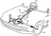
図1は本発明の参考例のステアリング装置101を車両に取り付けた状態を示す全体斜視図である。図1に示すように、中空円筒状のコラム102が車体に取付けられ、このコラム102にはステアリングシャフト104が回転可能に軸支されている。ステアリングシャフト104には、その右端(車体後方側)にステアリングホイール103が装着され、ステアリングシャフト104の左端(車体前方側)には、自在継手105を介して中間シャフト106が連結されている。
( Reference example )
FIG. 1 is an overall perspective view showing a state in which a
中間シャフト106は、雄スプラインが形成された中実の中間インナーシャフト106aと、雌スプラインが形成された中空円筒状の中間アウターシャフト106bで構成され、中間インナーシャフト106aの雄スプラインが、中間アウターシャフト106bの雌スプラインに伸縮可能(摺動可能)に、かつ回転トルクを伝達可能に嵌合している。
The
さらに、中間アウターシャフト106bの車体後方側が上記自在継手105に連結され、中間インナーシャフト106aの車体前方側が自在継手107に連結されている。自在継手107には、ステアリングギヤ108の図示しないラックに噛合うピニオンが連結されている。
Furthermore, the vehicle body rear side of the intermediate
運転者がステアリングホイール103を回転操作すると、ステアリングシャフト104、自在継手105、中間シャフト106、自在継手107を介して、その回転力がステアリングギヤ108に伝達され、ラックアンドピニオン機構を介して、タイロッド109を移動し、操舵輪110の操舵角を変えることができる。
When the driver rotates the
図2は本発明のステアリング装置の要部を示す一部を断面した正面図、図3(a)は本発明の参考例のブッシュ近傍の拡大断面図であり、図3(b)は図3(a)のP部拡大断面図である。図2、図3に示すように、アッパーコラム(アウターコラム)1は、アッパー車体取付けブラケット52によって、図示しない車体に固定されている。中空円筒状のアッパーコラム1の車体前方側(図2の左側)には、アッパーコラム1の内周面に、中空円筒状の第1のロアーコラム(インナーコラム)21の外周面が、軸方向にテレスコピック位置調整可能に密に嵌合している。
2 is a front view showing a part of the main part of the steering device of the present invention, FIG. 3 (a) is an enlarged sectional view of the vicinity of the bush of the reference example of the present invention, and FIG. 3 (b) is FIG. It is the P section expanded sectional view of (a). As shown in FIGS. 2 and 3, the upper column (outer column) 1 is fixed to a vehicle body (not shown) by an upper vehicle
第1のロアーコラム21の車体前方側(図2の左側)には、第1のロアーコラム21の外周面213に、中空円筒状の第2のロアーコラム(インナーコラム)22の内周面221が、軸方向にコラプス移動可能に密に嵌合している。第2のロアーコラム22の車体前方端は、ロアー車体取付けブラケット51によって、図示しない車体に枢動可能に固定されている。第2のロアーコラム22の内周面221は第1のロアーコラム21の外周面213にかしめ加工によって締め付けられており、二次衝突時に車体前方側に衝撃力が加わると、かしめ部分が変形して、第2のロアーコラム22に対して第1のロアーコラム21が車体前方側にコラプス移動する。
On the vehicle body front side (left side in FIG. 2) of the first
アッパーコラム1の軸心には雌ステアリングシャフト(アッパーステアリングシャフト)31が挿入され、アッパーコラム1の内周面の右端(アッパー側)に圧入された転がり軸受(図示せず)によって、雌ステアリングシャフト31の右端(アッパー側)が回転可能に軸支されている。雌ステアリングシャフト31の右端(車体後方側)には、図1のステアリングホイール103が装着されている。
A female steering shaft (upper steering shaft) 31 is inserted into the shaft center of the
第2のロアーコラム22の内周面221には、雄ステアリングシャフト32が挿入され、第2のロアーコラム22の内周面221の左端(ロアー側)に圧入された転がり軸受(深溝玉軸受)41によって、雄ステアリングシャフト32の左端(ロアー側)が回転可能に軸支されている。雄ステアリングシャフト32の右側には、雄スプライン321が形成され、雌ステアリングシャフト31の左側に形成された雌スプライン311に軸方向に相対的に移動可能に、かつ回転トルクを伝達可能にスプライン係合している。
A rolling bearing (deep groove ball bearing) in which a
図3(a)、図3(b)に示すように、第1のロアーコラム21の内周面は、第1のロアーコラム21の左端(ロアー側)から所定長にわたって装着面212が形成されている。そして、装着面212の右端(アッパー側)に隣接して内周面211が形成されている。装着面212および内周面211はどちらも円筒形であり、その内径寸法は装着面212よりも内周面211の方が小さくなっている。装着面212と内周面211との間には段差部214が形成されている。雌ステアリングシャフト31の外周面312かつ軸方向で見てスプライン嵌合部と第1のロアーコラム21の装着面212との間には、図4に示す合成樹脂製のブッシュ6が介挿されている。図4に示すように、ブッシュ6は中空円筒状で、軸方向の全長に渡ってスリット61が1個形成されている。
As shown in FIGS. 3A and 3B, the inner circumferential surface of the first
ブッシュ6の外周面62には、軸方向(図3(b)の左右方向)の中間部に環状凹溝63が形成され、環状凹溝63に断面が円形で環状のOリング(弾性部材)64が挿入されている。Oリング64は、合成ゴム等の弾性材料で形成されている。
On the outer
ブッシュ6の内周面66には、軸方向の中間部に円筒面661が形成され、軸方向の両端部にテーパー面662、662が形成されている。テーパー面662、662は、軸方向の端部側が軸心から離れる方向に傾斜して形成されている。ブッシュ6を第1のロアーコラム21の装着面212に挿入する前の状態では、ブッシュ6の円筒面661の内径寸法は、雌ステアリングシャフト31の外周面312の外径寸法よりも若干大きく形成されている。
On the inner
ブッシュ6を第1のロアーコラム21の装着面212に挿入すると、ブッシュ6はスリット61の間隔が狭まって縮径し、第1のロアーコラム21の内周面211に容易に挿入することができる。縮径したブッシュ6を第1のロアーコラム21の装着面212に挿入して行き、第1のロアーコラム21の内周に形成された段差部(図3(b)参照)214にブッシュ6の一方の端面に当接させる。その後、装着面212に形成されている内周溝215にC形止め輪又はCリング等の止め輪7を嵌入させ、ブッシュ6の他方の端面に当接させることで、ブッシュ6の軸方向移動が阻止される。
When the bush 6 is inserted into the mounting
また、Oリング64が第1のロアーコラム21の内周面211に押圧されて潰れ、Oリング64の弾性力によって、ブッシュ6の円筒面661の内径寸法が、雌ステアリングシャフト31の外周面312の外径寸法よりも若干小さくなる。Oリング64は円筒面661と同一の軸方向位置に配置されているため、Oリング64の弾性力によって、ブッシュ6の円筒面661を精度良く縮径することができる。
Further, the O-
その後、雌ステアリングシャフト31を組み込んだアッパーコラム1を第1のロアーコラム21に外嵌する。また、雄ステアリングシャフト32を組み込んだ第2のロアーコラム22を第1のロアーコラム21に外嵌し、第1のロアーコラム21の外周面213にかしめ加工によって締め付ける。
Thereafter, the
ブッシュ6の内周面66には、軸方向の両端部にテーパー面662、662が形成されているため、雌ステアリングシャフト31の外周面312はテーパー面662に案内されて、ブッシュ6の円筒面661に円滑に挿入される。また、ブッシュ6の軸方向の両端部にテーパー面662、662が形成されているため、テレスコピック位置調整時に、雌ステアリングシャフト31の外周面312は、ブッシュ6の円筒面661に沿って円滑に摺動することができる。
Since the inner
雌ステアリングシャフト31の外周面312がブッシュ6の円筒面661に挿入されると、Oリング64の弾性力によって、雌ステアリングシャフト31の外周面312がブッシュ6の円筒面661によって締め付けられる。ブッシュ6が雌ステアリングシャフト31の外周面312を締め付ける軸方向位置は、雄ステアリングシャフト32と雌ステアリングシャフト31のスプライン係合部である。
When the outer
本発明の参考例では、雌ステアリングシャフト31の外周面312とブッシュ6の円筒面661との間に所定の摩擦力が生じて、ステアリングホイール103の座りが良好になり、高速走行中のステアリングホイール103の操縦安定性が向上する。また、Oリング64が第1のロアーコラム21の内周面211に押圧されて潰れた状態になっているため、雌ステアリングシャフト31の振動がOリング64によって吸収され、車軸の振動がステアリングホイール103に伝達しにくくなるため、操舵感が向上する。
In the reference example of the present invention, a predetermined frictional force is generated between the outer
(実施例)
次に本発明の実施例について説明する。図5(a)は本発明の実施例のブッシュの拡大正面図であり、(b)は(a)のB−B断面図である。以下の説明では、上記参考例と異なる構造部分についてのみ説明し、重複する説明は省略する。また、同一部品には同一番号を付して説明する。実施例は参考例の変形例であって、参考例の円筒面661に代えて軸方向にわたって複数の円筒面663を形成した例である。
( Example )
Next, examples of the present invention will be described. Fig.5 (a) is an enlarged front view of the bush of the Example of this invention, (b) is BB sectional drawing of (a). In the following description, only a structural part different from the above-described reference example will be described, and redundant description will be omitted. Further, the same parts will be described with the same numbers. The embodiment is a modification of the reference example , in which a plurality of
図5(b)に示すとおり、ブッシュ6の内周面66の軸方向両端部に凸部665、665を配置し、その内周面に円筒面663、663を形成している。2つの凸部665の間には、円筒面663の内径よりも大きな内径で、図5(b)から見て断面がR形状の凹部664が形成されている。このようにすることで、雌ステアリングシャフト31の外周面312とブッシュ6の円筒面663、663との摺動性を安定させるためにグリスを塗布した場合、凹部664にグリスが保持され、長期にわたって良好な摩擦力を維持することができる。また、雌ステアリングシャフト31の外周面312と軸方向二箇所で接触することから、雌ステアリングシャフト31との接触が安定する。
As shown in FIG. 5B,
本発明の実施例では、雌ステアリングシャフト31の外周面312とブッシュ6の円筒面663、663とが軸方向二箇所で接触しているので雌ステアリングシャフト31との接触が安定するとともに、摺動性を安定させるためにグリスを塗布した場合、凹部664にグリスが保持され、長期にわたって摩擦力が安定し、高速走行中のステアリングホイール103の操縦安定性が向上する。
In an embodiment of the present invention, together with contact with the
上記参考例及び実施例では、断面が円形のOリング64を使用しているが、合成ゴム製で断面がX字形状または断面がU字形状の環状リングを使用してもよい。上記参考例及び実施例では、ブッシュ6には、軸方向の全長に渡って1個のスリット61が形成されているが、円周上の複数箇所に、ブッシュ6の軸方向の長さよりも短いスリットを形成してもよい。
In the reference examples and examples, the O-
また、上記参考例及び実施例は、アッパーコラムがアウターコラムで、ロアーコラムがインナーコラムのステアリング装置に適用しているが、アッパーコラムがインナーコラムで、ロアーコラムがアウターコラムのステアリング装置に適用してもよい。 In the above reference example and embodiment, the upper column is an outer column and the lower column is applied to the inner column steering device, but the upper column is the inner column and the lower column is applied to the outer column steering device. May be.
また、上記参考例及び実施例は、アッパーステアリングシャフトが雌ステアリングシャフトであり、ロアーステアリングシャフトが雄ステアリングシャフトのステアリング装置に適用しているが、アッパーステアリングシャフトが雄ステアリングシャフトであり、ロアーステアリングシャフトが雌ステアリングシャフトのステアリング装置に適用してもよい。 In the above reference example and embodiment, the upper steering shaft is a female steering shaft, and the lower steering shaft is applied to a steering device of a male steering shaft. However, the upper steering shaft is a male steering shaft, and the lower steering shaft. May be applied to a steering device for a female steering shaft.
101 ステアリング装置
102 コラム
103 ステアリングホイール
104 ステアリングシャフト
105 自在継手
106 中間シャフト
106a 中間インナーシャフト
106b 中間アウターシャフト
107 自在継手
108 ステアリングギヤ
109 タイロッド
110 操舵輪
1 アッパーコラム(アウターコラム)
21 第1のロアーコラム(インナーコラム)
211 内周面
212 装着面
213 外周面
214 段差部
215 内周溝
22 第2のロアーコラム(インナーコラム)
221 内周面
31 雌ステアリングシャフト(アッパーステアリングシャフト)
311 雌スプライン
312 外周面
32 雄ステアリングシャフト(ロアーステアリングシャフト)
321 雄スプライン
41 転がり軸受(深溝玉軸受)
51 ロアー車体取付けブラケット
52 アッパー車体取付けブラケット
6 ブッシュ
61 スリット
62 外周面
63 環状凹溝
64 Oリング(弾性部材)
66 内周面
661 円筒面
662 テーパー面
663 円筒面
664 凹部
7 止め輪
DESCRIPTION OF
21 First lower column (inner column)
211 Inner
221 Inner
311
321
51 Lower
66 Inner
Claims (2)
上記ロアーコラムに軸方向に相対的に摺動可能に嵌合されたアッパーコラム、
上記アッパーコラムのアッパー側に設けられた転がり軸受によって上記アッパーコラムに回転可能に軸支され、車体後方側にステアリングホイールが装着される雌ステアリングシャフト、
上記ロアーコラムのロアー側に設けられた転がり軸受によって上記ロアーコラムに回転可能に軸支され、上記雌ステアリングシャフトに軸方向に相対的に移動可能に、かつ回転トルクを伝達可能に係合して、上記ステアリングホイールの回転を車輪に伝達する雄ステアリングシャフト、
上記ロアーコラムの内周面と雌ステアリングシャフトの外周面との間に介挿され、外周面には軸方向の中央に環状凹溝を有し、内周面の軸方向両端部には上記雌ステアリングシャフトの外周面と接する凸部が形成され、これら両端凸部間の中央に凹部が形成され、かつ、軸方向の全長に渡って1個のスリットが形成された中空円筒状のブッシュ、
上記ブッシュの外周面とロアーコラムの内周面との間に介挿され、上記雌ステアリングシャフトを、テレスコピック摺動を可能に、かつ、回転可能に軸支し、ブッシュを縮径する方向に付勢して、ブッシュの内周面を雌ステアリングシャフトの外周面に押圧する環状の弾性部材を備えたこと
を特徴とするステアリング装置。 Lower column,
An upper column fitted to the lower column so as to be relatively slidable in the axial direction;
A female steering shaft that is rotatably supported on the upper column by a rolling bearing provided on the upper side of the upper column, and a steering wheel is mounted on the rear side of the vehicle body;
A rolling bearing provided on the lower side of the lower column is rotatably supported by the lower column and engaged with the female steering shaft so as to be relatively movable in the axial direction and capable of transmitting rotational torque. A male steering shaft for transmitting the rotation of the steering wheel to the wheel,
It is inserted between the inner peripheral surface of the lower column and the outer peripheral surface of the female steering shaft. The outer peripheral surface has an annular groove in the center in the axial direction. A hollow cylindrical bush having a convex portion in contact with the outer peripheral surface of the steering shaft, a concave portion formed in the center between the convex portions on both ends, and a single slit formed over the entire length in the axial direction;
It is inserted between the outer peripheral surface of the bush and the inner peripheral surface of the lower column. A steering apparatus comprising an annular elastic member that presses the inner peripheral surface of the bush against the outer peripheral surface of the female steering shaft.
Priority Applications (1)
| Application Number | Priority Date | Filing Date | Title |
|---|---|---|---|
| JP2011225718A JP5799735B2 (en) | 2011-10-13 | 2011-10-13 | Steering device |
Applications Claiming Priority (1)
| Application Number | Priority Date | Filing Date | Title |
|---|---|---|---|
| JP2011225718A JP5799735B2 (en) | 2011-10-13 | 2011-10-13 | Steering device |
Publications (3)
| Publication Number | Publication Date |
|---|---|
| JP2013086527A JP2013086527A (en) | 2013-05-13 |
| JP2013086527A5 JP2013086527A5 (en) | 2014-07-24 |
| JP5799735B2 true JP5799735B2 (en) | 2015-10-28 |
Family
ID=48530909
Family Applications (1)
| Application Number | Title | Priority Date | Filing Date |
|---|---|---|---|
| JP2011225718A Active JP5799735B2 (en) | 2011-10-13 | 2011-10-13 | Steering device |
Country Status (1)
| Country | Link |
|---|---|
| JP (1) | JP5799735B2 (en) |
Families Citing this family (1)
| Publication number | Priority date | Publication date | Assignee | Title |
|---|---|---|---|---|
| DE102018127029A1 (en) * | 2018-10-30 | 2020-04-30 | Schaeffler Technologies AG & Co. KG | Acoustically optimized storage unit |
Family Cites Families (2)
| Publication number | Priority date | Publication date | Assignee | Title |
|---|---|---|---|---|
| JP4273703B2 (en) * | 2002-05-09 | 2009-06-03 | オイレス工業株式会社 | Bush bearing |
| JP2006069360A (en) * | 2004-09-01 | 2006-03-16 | Nsk Ltd | Steering column device |
-
2011
- 2011-10-13 JP JP2011225718A patent/JP5799735B2/en active Active
Also Published As
| Publication number | Publication date |
|---|---|
| JP2013086527A (en) | 2013-05-13 |
Similar Documents
| Publication | Publication Date | Title |
|---|---|---|
| JP5664523B2 (en) | Steering device | |
| EP2724915B1 (en) | Position adjustment device for electric steering wheel | |
| JP2007182213A (en) | Steering device | |
| KR20110092456A (en) | Rack bar supporting device of steering apparatus for vehicle | |
| JP2007099260A (en) | Steering device | |
| JP5268027B2 (en) | Energy absorbing steering column | |
| JP5799735B2 (en) | Steering device | |
| JP5167995B2 (en) | Steering device | |
| KR101427440B1 (en) | Rack Bar Supporting Device of Steering Apparatus for Vehicle | |
| JP5782875B2 (en) | Steering device | |
| JP2013086527A5 (en) | ||
| JP5664452B2 (en) | Steering device | |
| JP2004009920A (en) | Impact-absorbing steering device | |
| JP2013035328A (en) | Steering apparatus | |
| JP5664437B2 (en) | Steering device | |
| JP2013060170A (en) | Steering device | |
| JP2013103544A (en) | Steering apparatus | |
| JP2014040210A (en) | Steering system | |
| JP5278446B2 (en) | Steering device | |
| KR101764934B1 (en) | Rack Bar Supporting Device of Steering Apparatus for Vehicle | |
| JP2014156158A (en) | Steering device | |
| JP2014141225A (en) | Steering device | |
| JP2011093444A (en) | Shock absorbing type steering device | |
| JP2014184860A (en) | Steering device | |
| JP2014139462A (en) | Steering device |
Legal Events
| Date | Code | Title | Description |
|---|---|---|---|
| A521 | Written amendment |
Free format text: JAPANESE INTERMEDIATE CODE: A523 Effective date: 20140609 |
|
| A621 | Written request for application examination |
Free format text: JAPANESE INTERMEDIATE CODE: A621 Effective date: 20140609 |
|
| RD02 | Notification of acceptance of power of attorney |
Free format text: JAPANESE INTERMEDIATE CODE: A7422 Effective date: 20140609 |
|
| A131 | Notification of reasons for refusal |
Free format text: JAPANESE INTERMEDIATE CODE: A131 Effective date: 20150224 |
|
| A977 | Report on retrieval |
Free format text: JAPANESE INTERMEDIATE CODE: A971007 Effective date: 20150227 |
|
| A521 | Written amendment |
Free format text: JAPANESE INTERMEDIATE CODE: A523 Effective date: 20150407 |
|
| TRDD | Decision of grant or rejection written | ||
| A01 | Written decision to grant a patent or to grant a registration (utility model) |
Free format text: JAPANESE INTERMEDIATE CODE: A01 Effective date: 20150728 |
|
| A61 | First payment of annual fees (during grant procedure) |
Free format text: JAPANESE INTERMEDIATE CODE: A61 Effective date: 20150810 |
|
| R150 | Certificate of patent or registration of utility model |
Ref document number: 5799735 Country of ref document: JP Free format text: JAPANESE INTERMEDIATE CODE: R150 |