JP5796292B2 - Encoder installation method - Google Patents
Encoder installation method Download PDFInfo
- Publication number
- JP5796292B2 JP5796292B2 JP2011000743A JP2011000743A JP5796292B2 JP 5796292 B2 JP5796292 B2 JP 5796292B2 JP 2011000743 A JP2011000743 A JP 2011000743A JP 2011000743 A JP2011000743 A JP 2011000743A JP 5796292 B2 JP5796292 B2 JP 5796292B2
- Authority
- JP
- Japan
- Prior art keywords
- encoder
- rotating
- rotating shaft
- bolt
- rotation
- Prior art date
- Legal status (The legal status is an assumption and is not a legal conclusion. Google has not performed a legal analysis and makes no representation as to the accuracy of the status listed.)
- Active
Links
Images


Description
本発明は、エンコーダの取り付け方法に関するものである。 The present invention relates to a method of attaching the encoder.
例えばモータの回転軸など回転体の回転数や回転角度を検出する装置として、エンコーダが知られている(特許文献1)。エンコーダは、例えばモータ(測定対象)の回転軸などに取り付けられて用いられる。エンコーダの一例として、所定の光反射パターン及び磁気パターンが形成された回転部を回転軸と一体的に回転させ、光反射パターンに光を照射して反射光を読み取ると共に、例えば磁気パターンの変化を検出することで、モータの回転軸の回転数や回転角度を検出できるようになっている。
従来、このようなエンコーダをモータ等に固定する手段として、モータ側にモータ軸と同心の取れているインロー構造を設け、該インロー構造を用いてエンコーダがモータに固定されるようになっている。
For example, an encoder is known as a device that detects the rotation speed and rotation angle of a rotating body such as a rotating shaft of a motor (Patent Document 1). The encoder is used by being attached to a rotating shaft of a motor (measurement target), for example. As an example of an encoder, a rotating part on which a predetermined light reflection pattern and a magnetic pattern are formed is rotated integrally with a rotating shaft, and the reflected light is read by irradiating light to the light reflection pattern. By detecting, the rotation speed and rotation angle of the rotation shaft of the motor can be detected.
Conventionally, as a means for fixing such an encoder to a motor or the like, an inlay structure concentric with the motor shaft is provided on the motor side, and the encoder is fixed to the motor using the inlay structure.
しかしながら、モータ側にインロー構造を設ける場合、モータの加工に工数が掛かるとともに、モータ軸とインロー構造との同心度を精度良く構成することが難しいといった問題があった。 However, when the spigot structure is provided on the motor side, there are problems that it takes time to process the motor and it is difficult to accurately configure the concentricity between the motor shaft and the spigot structure.
本発明の態様は、上述のようなインロー構造を不要とすることでモータに対する取り付け、或いは取付作業を簡略化できるエンコーダの取り付け方法を提供することを目的としている。 Aspect of the present invention is intended to provide attachment or mounting how the encoder of the mounting operation can be simplified with respect to the motor by eliminating the need for spigot structure as described above.
本発明に係るエンコーダは、所定のパターンが形成された回転符号板および測定対象の回転軸に固定するための固定孔を有し、前記回転軸に固定可能な円板部と、前記所定のパターンを検出する検出部を含む基板部と、前記基板部を保持するとともに、前記円板部の一部と嵌合して前記円板部を収容する本体部と、前記回転符号板および前記検出部が前記固定孔に対して同心が取れた状態で前記円板部を前記基板部に対して一体に保持する保持部材と、を備える。 An encoder according to the present invention has a rotary code plate on which a predetermined pattern is formed, a fixing hole for fixing to a rotating shaft to be measured, a disc portion that can be fixed to the rotating shaft, and the predetermined pattern A substrate unit including a detection unit for detecting the substrate, a main body unit that holds the substrate unit and fits with a part of the disk unit and accommodates the disk unit, the rotary code plate, and the detection unit Includes a holding member that integrally holds the disk portion with respect to the substrate portion while being concentric with the fixing hole.
本発明に係るエンコーダの取り付け方法は、本発明に係るエンコーダを測定対象の回転軸に取付けるエンコーダの取付方法であって、前記固定孔に前記回転軸を挿入した状態で前記本体部を前記測定対象上に配置する工程と、前記円板部の一部が前記本体部に嵌合した状態で当該本体部を前記測定対象に固定する工程と、前記保持部材を取り外すことで前記円板部及び前記本体部の嵌合状態を解消させる工程と、前記円板部と前記回転軸とを固定する工程と、を有する。 An encoder mounting method according to the present invention is an encoder mounting method in which the encoder according to the present invention is mounted on a rotating shaft to be measured, and the main body portion is mounted on the measuring object in a state where the rotating shaft is inserted into the fixed hole. A step of disposing the disk portion, a step of fixing the main body portion to the measurement object in a state in which a part of the disk portion is fitted to the main body portion, A step of eliminating the fitting state of the main body portion, and a step of fixing the disc portion and the rotating shaft.
本発明に係るモータ装置は、本発明に係るエンコーダを備える。 The motor device according to the present invention includes the encoder according to the present invention.
本発明の態様によれば、エンコーダの取り付け、或いは交換作業を簡略化できる。 According to the aspect of the present invention, it is possible to simplify the installation or replacement work of the encoder.
以下、図面を参照して、本発明の実施の形態を説明する。
(第一実施形態)
エンコーダは、モータなどの回転体(モータ装置)の回転数や回転速度を検出する装置である。図1は、第一実施形態に係るエンコーダ100の全体構成を示す断面図であり、モータに取り付けられる前の状態を示す図である。図1に示すように、エンコーダ100は、筐体(本体部)4、検出部(基板部)30、及び回転部(円板部)15を有している。
Embodiments of the present invention will be described below with reference to the drawings.
(First embodiment)
The encoder is a device that detects the number of rotations and the rotation speed of a rotating body (motor device) such as a motor. FIG. 1 is a cross-sectional view showing the overall configuration of the
検出部30は、検出基板5及び光センサ(検出部)8を有している。検出基板5は、例えば平面視円形に形成された板状部材である。検出部30は、回転部15に形成された光反射パターン10に光を照射し、光センサ8が反射光を検出することで光反射パターン10の移動角度を検出することができる。検出部30(検出基板5)は、筐体4に取り付けられている。
The
また、筐体4及び検出部30には、エンコーダ100とモータ本体1aとを固定するための固定ネジ40(図2参照)を挿通させるための貫通孔41がそれぞれ形成されている。エンコーダ100は、固定ネジ40を介してモータ本体1aに一体的に接合可能となっている(図2参照)。
Further, the
回転部15は、回転本体部31、円板部(回転符号板)9、及び、凸部32を有している。円板部9は回転本体部31の一端側に設けられた円板形状からなるものであり、表面に光反射パターン10が形成されている。凸部32は回転本体部31の他端側に設けられた円柱形状からなるものであり、回転部15が検出基板5に固定された状態において、筐体4に嵌合されている。
The
回転部15には、中央に貫通孔33が設けられている。貫通孔33の一端部は、モータ本体1aの回転軸2を固定するための回転軸固定孔33aを構成しており、他端側は回転部15をモータ本体1aの回転軸2に固定するためのボルト(図2参照)3が配置されるボルト配置孔33bを構成している。また、貫通孔33における回転軸固定孔33aとボルト配置孔33bとの間は、タップ部33cを構成している。タップ部33cはタップによって形成された雌ネジからなる。なお、タップ部33cの内径は、ボルト3の軸部3bの外径よりも大きく構成されている。すなわち、ボルト3の軸部3bは、タップ部33cに対して螺合しない構成となっている(図2参照)。
The rotating
回転部15は、ボルト42(保持部材)を介して検出基板5に固定されている。検出基板5には、ボルト42を挿通させるための開口部5aが形成されている。ボルト42は、頭部42aと軸部42bとを含んでいる。上記開口部5aは、ボルト42の頭部42aよりも小さく設定されている。一例として、ボルト42は、回転部15のタップ部33cに螺合することで回転部15を検出基板5に固定している。
The rotating
筐体(本体部)4は、平面視円形に形成された円筒状からなるものであり、モータ本体1aの外径と略同じ大きさを有するものである。筐体4は、第1の凹部4a、第2の凹部4b、及び嵌合部4cと、を含み、内部空間において回転部15を収容している。第1の凹部4aは、検出基板5との間で回転部15(回転本体部31および円板部9)を収容する空間を構成している。また、第2の凹部4bは、回転部15が回転軸2に固定された際、モータ本体1aとの間で回転部15の凸部32を収容する空間を構成するためのものである(図2参照)。
The housing (main body part) 4 is formed in a cylindrical shape formed in a circular shape in plan view, and has approximately the same size as the outer diameter of the motor
本実施形態に係るエンコーダ100は、円板部9および検出部30が回転軸固定孔33aに対して同心が取れた状態(同心状態)で、ボルト42により回転部15と検出基板5とが一体に保持された状態で組み立てられたものとなっている。
In the
ここで、エンコーダ100において円板部9と検出部30との同心を取った状態で組み立てる方法について説明する。
回転部15は、エンコーダ100を取り付けるモータの回転軸2と同じ外径の基準軸に同心を取った状態で加工されたものとなっている。さらに、回転部15は、凸部32の外径と貫通孔33(又は回転軸固定孔33a)とが基準軸と同軸になるように加工されたものとなっている。また、円板部9の光反射パターン10も偏心取り作業により、基準軸と同軸加工が施された回転軸固定孔33aに対して同心が取られた状態で形成されたものとなっている。
Here, a method of assembling the
The rotating
嵌合部4cは、上記回転部15における凸部32を嵌合させる円形状の開口をなすものである。また、嵌合部4cは、凸部32に嵌合する回転部15と同心が取れた状態となるように上記開口が構成されている。上述のように回転部15は凸部32の外径と回転軸固定孔33aとが同心状(同心状態)となっているため、回転部15と同心が取られた筐体4(嵌合部4c)は回転軸固定孔33aに対しても同心が取られた状態となっている。
The
検出部30は、ボルト42(保持部材)を介して検出基板5と回転部15とが固定されている。検出部30は、光センサ8が嵌合部4cと同心がとれた状態となっている。すなわち、光センサ8は、上記の同心状態を満たすように検出基板5上に配置されている。この開口部5aは、回転軸固定孔33aに対して同心が取れた状態となっている。上述のように嵌合部4cは回転軸固定孔33aに対して同心が取れた状態で加工されているため、嵌合部4cと同心が取られた検出部30は回転軸固定孔33aに対しても同心が取られた状態となっている。
As for the
回転部15は、凸部32が筐体4の嵌合部4cに嵌合した状態で、検出基板5の開口部5a及び貫通孔33に挿通されたボルト42がタップ部33cに螺合することで検出基板5に固定されている。なお、ボルト42は、その先端部が回転軸固定孔33a内に突出するようにタップ部33cに螺合している。
The
このように、本実施形態に係るエンコーダ100は、円板部9および検出部30が回転軸固定孔33aに対して同心が取れた状態で、ボルト42により回転部15と検出基板5とが一体に保持された状態で組み立てられたものとなっている。
As described above, in the
図2は、エンコーダ100がモーター装置1の回転軸2に取り付けられたモータ装置1の全体構成を示す断面図である。
図2に示すように、エンコーダ100は、固定ネジ40を介して筐体4がモータ本体1aに固定されている。モータ本体1aには、回転軸2側の上端部に固定ネジ40を取り付けるための雌ねじ部1Aが形成されており、上記固定ネジ40が雌ねじ部1Aに螺合することで筐体4とモータ本体1aとが一体に保持されている。
FIG. 2 is a cross-sectional view showing the overall configuration of the
As shown in FIG. 2, in the
モータ装置1は、回転部15がボルト3により回転軸2に固定され、回転軸2と一体的に回転するようになっている。ボルト3は、頭部3aと軸部3bとを含み、軸部3bに形成されたネジ部3bbが回転軸2に形成された雌ねじ2aに螺合することで回転部15を回転軸2に固定している。
In the
回転部15は、光反射パターン10を所定の距離で検出部30の光センサ8に対向させて保持している。回転部15が回転軸2に固定された状態においては、円板面9aが回転軸2に垂直となり、回転部15の回転軸R方向は回転軸2の延在方向と同一方向となっている。回転部15は、回転軸2に固定された状態において、筐体4に接触しないように収容されている。
The rotating
ここで、モータ装置1に取り付けられたエンコーダ100の動作について説明する。
回転軸2が回転すると、当該回転軸2に一体的に取り付けられた回転部15及び光反射パターン10が回転軸2と一体的に回転する。検出部30については、回転軸2には接続されていないため、回転せずに静止した状態となる。
Here, the operation of the
When the
回転部15が回転すると、当該回転部15に形成された光反射パターン10が回転方向に移動する。上述の光センサ8は、光源から射出された光のうち光反射パターン10を介した反射光を読み取ることで光反射パターン10の移動角度等に基づいて回転軸2の回転情報(例、回転角度や回転数)を検出することができる。
When the
このようにして、エンコーダ100は、回転軸2の回転情報を検出可能となっている。本実施形態に係るモータ装置1は、上記エンコーダ100が取り付けられているので、回転軸2と円板部9及び検出部30とが精度良く位置出しされたものとなっており、回転軸2の回転制御を精度良く行うことができる。
In this way, the
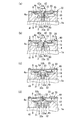
次に、図3に示す構成のモータ装置1に図1に示したエンコーダ100を取り付ける手順について説明する。
まず、図3(a)に示すように、回転軸固定孔33aに回転軸2を挿入させつつ、モータ本体1a上にエンコーダ100を配置する。本実施形態に係るエンコーダ100は、円板部9および検出部30が回転軸固定孔33aに対して同心が取れた状態で組み立てられているため、回転軸固定孔33aに挿入された回転軸2は円板部9及び検出部30に対して位置出しされたものとなる。なお、回転軸2は回転軸固定孔33aの途中まで挿入された状態となっている。ボルト42は、タップ部33cに螺合した状態にて、その先端部が回転軸固定孔33a内に突出しているが、先端部は回転軸2に当接していても構わない。
Next, a procedure for attaching the
First, as shown in FIG. 3A, the
本実施形態に係るエンコーダ100は、円板部9および検出部30が回転軸固定孔33aに対して同心が取れた状態となっているので、回転軸固定孔33a内に挿入された回転軸2は円板部9および検出部30に対して同心状(同心状態)に配置されたものとなる。
In the
続いて、図3(b)に示すように回転部15の凸部32が筐体4の嵌合部4cに嵌合した状態で、貫通孔41に固定ネジ40を挿通し、該固定ネジ40を用いて筐体4とモータ本体1aとを固定する。
Subsequently, as shown in FIG. 3B, the fixing
続いて、図3(c)に示すように、検出基板5と回転部15とを固定するボルト42を取り外す。これにより、回転部15と筐体4との嵌合状態が解消されることとなる。
一例として、ボルト42がタップ部33cから外れるに従って、回転部15が下方に移動して回転軸2が回転軸固定孔33aに完全に挿入された状態となる。また、回転部15が下方に移動するに従って、凸部32が嵌合部4cから外れた状態となる。
Subsequently, as illustrated in FIG. 3C, the
As an example, as the
続いて、図3(d)に示すように、回転部15を回転軸2にボルト3によって固定する。なお、ボルト3は、頭部3aの外径が検出基板5に形成された開口部5aの内径よりも小さいため、開口部5aを挿通し、ボルト配置孔33bに確実に配置されるようになる。よって、ボルト3は、軸部3bが回転軸2の雌ねじ2aに螺合することで回転部15と回転軸2とを確実に固定できる。
Subsequently, as shown in FIG. 3 (d), the rotating
以上述べたように本実施形態に係るエンコーダの取り付け方法によれば、円板部9および検出部30が回転軸固定孔33aに対して同心が取れたエンコーダ100を組み込むため、インロー構造をモータ本体1aに設ける事無く、回転軸2を回転軸固定孔33aに挿入した後、固定することで回転軸2と円板部9及び検出部30とが精度良く位置出しされたモータ装置1を容易に組み立てることができる。
As described above, according to the encoder mounting method according to the present embodiment, since the
このモータ装置1によれば、回転軸2と円板部9及び検出部30とが精度良く位置出しされているので、回転軸2の回転制御を精度良く行うことが可能であり、信頼性の高いものとなる。
According to the
なお、回転部15と検出基板5とを固定していた上記ボルト42は、回転軸2から回転部15を取り出す際の抜きネジとして使用することができる。一例として、回転軸2から回転部15を取り出す場合、はじめにボルト3を回転軸2から取り外す。その後、検出基板5の開口部5a内にボルト42を挿通させ、ボルト42をタップ部33cに螺合させる。
In addition, the said
図4に示すように、ボルト42がタップ部33cに入り込んでいくと、ボルト42は、その先端部が回転軸固定孔33a内に突出する。なお、図4では、検出基板5の図示を省略している。このようにボルト42をタップ部33cに螺合させることで、ボルト42の先端部を回転軸固定孔33a内に突出させることができる。これにより、回転部15の回転軸固定孔33a内から回転軸2を引く抜くことができる。なお、図4においては検出基板5の図示を省略している。
As shown in FIG. 4, when the
回転部15を回転軸2から引き抜いた後、筐体4とモータ本体1aとを固定している固定ネジ40を取り外すことで、エンコーダ100をモータ本体1aから取り外すことができる。
After pulling out the
このように本実施形態に係るエンコーダ100によれば、回転軸2に対する回転部15の取り外し工程を含む、モータ本体1aに対する取付或いは取り外し作業を簡便に行うことができる。よって、エンコーダ100は、モータ本体1aに対する着脱性に優れたものとなる。
As described above, according to the
(第二実施形態)
次に、本発明の第二実施形態に係る構成について説明する。なお、本実施形態と第一実施形態との違いは、エンコーダにおける検出基板と回転部とが複数の保持部材で固定されること、及びエンコーダとモータ本体とを固定する手段として保持部材を利用することであり、それ以外の構成については同一である。そのため、以下の説明では第一実施形態と同一の部材及び構成については、説明を省略もしくは簡略化するものとする。
(Second embodiment)
Next, a configuration according to the second embodiment of the present invention will be described. Note that the difference between this embodiment and the first embodiment is that the detection board and the rotating part of the encoder are fixed by a plurality of holding members, and that the holding member is used as a means for fixing the encoder and the motor body. That is, the other configurations are the same. Therefore, in the following description, the description of the same members and configurations as those in the first embodiment will be omitted or simplified.
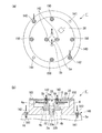
図5は本実施形態に係るエンコーダの全体構成を示す図であり、図5(a)はエンコーダの平面図であり、図5(b)はエンコーダの断面構成図である。
エンコーダ200は、図5(a),(b)に示すように、第一実施形態に係る構成と同様、筐体4、検出部30、及び回転部15を有している。筐体4には、エンコーダ200とモータ本体1aとを固定するためのボルト(保持部材)142(図6参照)を挿通させるための貫通孔141が設けられた固定部143が形成されている。固定部143は、筐体4の周囲を囲む鍔形状からなるものである。このようにエンコーダ200は、ボルト142を介してモータ本体1aに固定されることでモータ本体1aに一体的に接合可能となっている(図6参照)。
FIG. 5 is a diagram showing an overall configuration of the encoder according to the present embodiment, FIG. 5 (a) is a plan view of the encoder, and FIG. 5 (b) is a sectional configuration diagram of the encoder.
The
回転部15には、中央に貫通孔33が設けられている。貫通孔33の一端部は、回転軸2を固定するための回転軸固定孔33aを構成しており、他端側は回転部15を回転軸2に固定するためのボルト3が配置されるボルト配置孔33bを構成している。本実施形態では、貫通孔33における回転軸固定孔33aとボルト配置孔33bとの間には、タップ部が設けられない構成となっている。
The rotating
検出部30は、複数(本実施形態では、4本)のボルト142(保持部材)を介して検出基板5と回転部15とが固定されている。検出基板5には、上記貫通孔33を内部に臨ませる開口部5aが形成されている。この開口部5aは、回転軸固定孔33aに対して同心が取れた状態となっている。また、この開口部5aの外周を囲むように、上記ボルト142を挿通させる開口5bが形成されている。この開口5bも、回転軸固定孔33aに対して同心が取れた状態となっている。
In the
回転部15は、凸部32が筐体4の嵌合部4cに嵌合した状態にて、複数のボルト142が回転部15に設けられたネジ孔(雌ねじ)に螺合することで検出基板5に固定されている。
The
本実施形態においても、検出部30は、光センサ8が嵌合部4cと同心がとれた状態となっている。すなわち、光センサ8は、上記の同心状態を満たすように検出基板5上に配置されている。検出基板5は、筐体4にネジ150を介して固定されている。本実施形態においても、嵌合部4cは回転軸固定孔33aに対して同心が取れた状態で加工されているため、嵌合部4cと同心が取られた検出部30は回転軸固定孔33aに対しても同心が取られた状態となっている。
Also in the present embodiment, the
このように、本実施形態に係るエンコーダ200は、円板部9および検出部30が回転軸固定孔33aに対して同心が取れた状態で、ボルト142により回転部15と検出基板5とが一体に保持された状態で組み立てられたものとなっている。
As described above, in the
図6は、エンコーダ200がモータ装置1の回転軸2に取り付けられたモータ装置1´の全体構成を示す図であり、同図における上面図はモータ装置の平面構成を示し、下面図はモータ装置の断面構成を示している。図6に示すように、エンコーダ200は、回転部15と検出基板5とを固定していた複数のボルト142を介して筐体4がモータ本体1aに固定されている。
FIG. 6 is a diagram illustrating an overall configuration of a
モータ本体1aには、回転軸2側の上端部にボルト142を取り付けるための雌ねじ部1Aが形成されており、上記ボルト142が雌ねじ部1Aに螺合することで筐体4とモータ本体1aとが一体に保持されている。
The motor
モータ装置1´は、回転部15がボルト3により回転軸2に固定され、回転軸2と一体的に回転するようになっている。ボルト3は、軸部3bに形成されたネジ部が回転軸2に形成された雌ねじ2aに螺合している。
In the
次に、図6に示す構成のモータ装置1´に図5に示したエンコーダ200を取り付ける手順について図7乃至10を参照しながら説明する。なお、各同図における上面図はモータ装置の平面構成を示し、下面図はモータ装置の断面構成を示している。
まず、図7に示すように、回転軸固定孔33aに回転軸2を挿入させつつ、モータ本体1a上にエンコーダ200を配置する。このとき、エンコーダ200は、円板部9および検出部30が回転軸固定孔33aに対して同心が取れた状態となっているため、回転軸固定孔33aに挿入された回転軸2は円板部9及び検出部30に対して位置出しされたものとなる。このとき、回転軸2は回転軸固定孔33aの途中まで挿入された状態とされている。
Next, a procedure for attaching the
First, as shown in FIG. 7, the
続いて、回転部15の凸部32が筐体4の嵌合部4cに嵌合した状態で、筐体4をモータ本体1aに固定する。本実施形態では、図8に示すように、回転部15と検出基板5とを固定している4本のボルト142のうち、対角に配置される2本を外し、外したボルト142を筐体4の固定部143に設けられた貫通孔141を挿通させ、該ボルト142を用いて筐体4をモータ本体1aに固定する。このとき、回転部15は、2本のボルトで検出基板5に固定されているため、凸部32は筐体4の嵌合部4cに嵌合したままの状態となっている。
Subsequently, the
そして、図9に示すように、残りの2本のボルト142を外し、外したボルト142を用いて筐体4をモータ本体1aに固定する。2本のボルト142が外れると、回転部15は下方に移動することで回転軸2が完全に回転軸固定孔33aに挿入された状態となる。また、回転部15は下方に移動するに従って、凸部32が嵌合部4cから外れた状態となる。
Then, as shown in FIG. 9, the remaining two
このように本実施形態においては、取り外したボルト142を用いて筐体4とモータ本体1aとを順次固定することで、筐体4とモータ本体1aとを固定する工程と、ボルト142を取り外すことで回転部15及び筐体4の嵌合状態を解消させる工程と、を同時に(同期させて)行うことができる。
As described above, in the present embodiment, the
続いて、図10に示すように、回転部15を回転軸2にボルト3によって固定する。ボルト3は、軸部3bが回転軸2の雌ねじ2aに螺合することで回転部15と回転軸2とを確実に固定することができる。
Subsequently, as shown in FIG. 10, the rotating
以上述べたように本実施形態に係るエンコーダの取り付け方法によれば、円板部9および検出部30が回転軸固定孔33aに対して同心が取れたエンコーダ200を組み込むため、インロー構造をモータ本体1aに設ける事無く、回転軸2を回転軸固定孔33aに挿入した後、固定することで回転軸2と円板部9及び検出部30とが精度良く位置出しされたモータ装置1´を容易に組み立てることができる。また、筐体4とモータ本体1aとを固定する手段として、回転部15と検出基板5とを固定するボルト142を再利用できるので、筐体4及びモータ本体1aを固定するためのネジ等を別途用意する必要を無くすことができる。従って、本実施形態に係るエンコーダ又はエンコーダの取り付け方法によれば、モータ装置の組み立てを低コストで短時間に行うことができる。
As described above, according to the encoder mounting method according to the present embodiment, the
本発明は上述した実施形態に係る構成に限定されることなく、発明の趣旨を逸脱しない範囲内において適宜変更可能である。 The present invention is not limited to the configuration according to the above-described embodiment, and can be appropriately changed without departing from the spirit of the invention.
1、1´…モータ装置、2…回転軸、3…ボルト(固定ねじ)、5…検出基板(基板部)、8…光センサ(検出部)、9…円板部(回転符号板)、15…回転部(円板部)、30…検出部(基板部)、31…本体部、33a…回転軸固定孔(固定孔)、33b…ボルト配置孔(取付孔)、33c…タップ部、42…ボルト(保持部材)、100,200…エンコーダ
DESCRIPTION OF
Claims (2)
前記固定孔に前記回転軸を挿入させつつ、前記本体部を前記測定対象上に配置する工程と、
前記円板部の一部が前記本体部に嵌合した状態で当該本体部を前記測定対象に固定する工程と、
前記保持部材を取り外すことで前記円板部及び前記本体部の嵌合状態を解消させる工程と、
前記円板部と前記回転軸とを固定し、前記円板部を前記回転軸とともに回転可能な状態とする工程と、
を有することを特徴とするエンコーダの取り付け方法。 While holding the said board | substrate part, the disk part which has the rotation code | symbol plate in which the predetermined pattern was formed, the fixing hole and the attachment hole, the board | substrate part containing the detection part which detects the said predetermined pattern, A main body portion that fits into a part of the disc portion and accommodates the disc portion, and the disc portion is concentric with the rotation code plate and the detection portion with respect to the fixing hole. In the state, the holding member is attached to the attachment hole through the substrate portion, and the encoder is integrally attached to the substrate portion and attached to the rotation shaft to be measured,
Placing the main body on the measurement object while inserting the rotating shaft into the fixed hole;
Fixing the main body part to the measurement object in a state in which a part of the disc part is fitted to the main body part;
Removing the holding member to eliminate the fitting state of the disk portion and the main body portion; and
Fixing the disk part and the rotating shaft, and making the disk part rotatable with the rotating shaft;
A method of attaching an encoder, comprising:
Priority Applications (1)
| Application Number | Priority Date | Filing Date | Title |
|---|---|---|---|
| JP2011000743A JP5796292B2 (en) | 2011-01-05 | 2011-01-05 | Encoder installation method |
Applications Claiming Priority (1)
| Application Number | Priority Date | Filing Date | Title |
|---|---|---|---|
| JP2011000743A JP5796292B2 (en) | 2011-01-05 | 2011-01-05 | Encoder installation method |
Related Child Applications (1)
| Application Number | Title | Priority Date | Filing Date |
|---|---|---|---|
| JP2015132827A Division JP6156448B2 (en) | 2015-07-01 | 2015-07-01 | Encoder and motor device |
Publications (3)
| Publication Number | Publication Date |
|---|---|
| JP2012141248A JP2012141248A (en) | 2012-07-26 |
| JP2012141248A5 JP2012141248A5 (en) | 2014-05-22 |
| JP5796292B2 true JP5796292B2 (en) | 2015-10-21 |
Family
ID=46677671
Family Applications (1)
| Application Number | Title | Priority Date | Filing Date |
|---|---|---|---|
| JP2011000743A Active JP5796292B2 (en) | 2011-01-05 | 2011-01-05 | Encoder installation method |
Country Status (1)
| Country | Link |
|---|---|
| JP (1) | JP5796292B2 (en) |
Families Citing this family (2)
| Publication number | Priority date | Publication date | Assignee | Title |
|---|---|---|---|---|
| JP5673821B2 (en) * | 2011-06-23 | 2015-02-18 | 株式会社ニコン | Encoder, encoder mounting method, and motor device |
| JP6849202B1 (en) * | 2020-09-29 | 2021-03-24 | 多摩川精機株式会社 | Encoder mounting structure and method using inro section |
Family Cites Families (5)
| Publication number | Priority date | Publication date | Assignee | Title |
|---|---|---|---|---|
| JPS6148719A (en) * | 1984-08-16 | 1986-03-10 | Fanuc Ltd | Optical rotary encoder |
| JPH0250366A (en) * | 1988-08-12 | 1990-02-20 | Sony Corp | Disk device |
| JP2001012968A (en) * | 1999-06-28 | 2001-01-19 | Canon Inc | Rotary encoder |
| JP5012502B2 (en) * | 2007-12-28 | 2012-08-29 | 株式会社ニコン | Encoder |
| JP2009210374A (en) * | 2008-03-04 | 2009-09-17 | Nikon Corp | Encoder and light receiving unit |
-
2011
- 2011-01-05 JP JP2011000743A patent/JP5796292B2/en active Active
Also Published As
| Publication number | Publication date |
|---|---|
| JP2012141248A (en) | 2012-07-26 |
Similar Documents
| Publication | Publication Date | Title |
|---|---|---|
| JP5673821B2 (en) | Encoder, encoder mounting method, and motor device | |
| CN212300237U (en) | Hall signal calibration device | |
| WO2016052342A1 (en) | Encoder, holding member, encoder attachment method, drive apparatus, robot apparatus, and stage apparatus | |
| JP2012073219A (en) | Rotary encoder and method for assembling rotary encoder | |
| JP6918738B2 (en) | Sensor system | |
| JP5796292B2 (en) | Encoder installation method | |
| US5883384A (en) | Rotational displacement information detection apparatus | |
| JP6156448B2 (en) | Encoder and motor device | |
| JP2014062770A (en) | Encoder, encoder assembling method, drive device, and robot device | |
| JP2011112441A (en) | Encoder, method for mounting encoder, and motor device | |
| CN111707177A (en) | Hall signal calibration device and assembly method thereof, and calibration method of Hall signal | |
| JP2010249519A (en) | Member and assembly for fixing read plate, and signal detecting device, as well as rotary encoder | |
| JP2018091739A (en) | Rotary encoder and manufacturing method therefor | |
| JP5012502B2 (en) | Encoder | |
| JP5109654B2 (en) | Encoder | |
| JP2011007734A (en) | Encoder and method of attaching the same | |
| JP2011117759A (en) | Encoder, motor device and mounting method for the encoder | |
| JP2020038081A (en) | Encoder | |
| JP7440351B2 (en) | positioning device | |
| JP5212732B2 (en) | Optical encoder | |
| JP5612714B2 (en) | Read plate fixing member, read plate fixing assembly, signal detection device, and rotary encoder | |
| JP5929024B2 (en) | ENCODER, ENCODER INSTALLATION METHOD, AND MOTOR DEVICE | |
| JP2011208976A (en) | Encoder mounting method and encoder | |
| JP2011112538A (en) | Encoder and method of fitting the same | |
| JP2000074693A (en) | Rotational displacement information detector |
Legal Events
| Date | Code | Title | Description |
|---|---|---|---|
| A621 | Written request for application examination |
Free format text: JAPANESE INTERMEDIATE CODE: A621 Effective date: 20131220 |
|
| A521 | Request for written amendment filed |
Free format text: JAPANESE INTERMEDIATE CODE: A523 Effective date: 20140404 |
|
| A977 | Report on retrieval |
Free format text: JAPANESE INTERMEDIATE CODE: A971007 Effective date: 20140728 |
|
| A131 | Notification of reasons for refusal |
Free format text: JAPANESE INTERMEDIATE CODE: A131 Effective date: 20140805 |
|
| A521 | Request for written amendment filed |
Free format text: JAPANESE INTERMEDIATE CODE: A523 Effective date: 20141006 |
|
| A02 | Decision of refusal |
Free format text: JAPANESE INTERMEDIATE CODE: A02 Effective date: 20150401 |
|
| A521 | Request for written amendment filed |
Free format text: JAPANESE INTERMEDIATE CODE: A523 Effective date: 20150625 |
|
| A911 | Transfer to examiner for re-examination before appeal (zenchi) |
Free format text: JAPANESE INTERMEDIATE CODE: A911 Effective date: 20150702 |
|
| TRDD | Decision of grant or rejection written | ||
| A01 | Written decision to grant a patent or to grant a registration (utility model) |
Free format text: JAPANESE INTERMEDIATE CODE: A01 Effective date: 20150721 |
|
| A61 | First payment of annual fees (during grant procedure) |
Free format text: JAPANESE INTERMEDIATE CODE: A61 Effective date: 20150803 |
|
| R150 | Certificate of patent or registration of utility model |
Ref document number: 5796292 Country of ref document: JP Free format text: JAPANESE INTERMEDIATE CODE: R150 |
|
| R250 | Receipt of annual fees |
Free format text: JAPANESE INTERMEDIATE CODE: R250 |
|
| R250 | Receipt of annual fees |
Free format text: JAPANESE INTERMEDIATE CODE: R250 |
|
| R250 | Receipt of annual fees |
Free format text: JAPANESE INTERMEDIATE CODE: R250 |
|
| R250 | Receipt of annual fees |
Free format text: JAPANESE INTERMEDIATE CODE: R250 |
|
| R250 | Receipt of annual fees |
Free format text: JAPANESE INTERMEDIATE CODE: R250 |
|
| R250 | Receipt of annual fees |
Free format text: JAPANESE INTERMEDIATE CODE: R250 |