JP5793285B2 - Locking device for fixing automotive components - Google Patents
Locking device for fixing automotive components Download PDFInfo
- Publication number
- JP5793285B2 JP5793285B2 JP2010204918A JP2010204918A JP5793285B2 JP 5793285 B2 JP5793285 B2 JP 5793285B2 JP 2010204918 A JP2010204918 A JP 2010204918A JP 2010204918 A JP2010204918 A JP 2010204918A JP 5793285 B2 JP5793285 B2 JP 5793285B2
- Authority
- JP
- Japan
- Prior art keywords
- braking
- component
- actuator
- locking device
- vehicle
- Prior art date
- Legal status (The legal status is an assumption and is not a legal conclusion. Google has not performed a legal analysis and makes no representation as to the accuracy of the status listed.)
- Expired - Fee Related
Links
Images


Classifications
-
- E—FIXED CONSTRUCTIONS
- E05—LOCKS; KEYS; WINDOW OR DOOR FITTINGS; SAFES
- E05C—BOLTS OR FASTENING DEVICES FOR WINGS, SPECIALLY FOR DOORS OR WINDOWS
- E05C17/00—Devices for holding wings open; Devices for limiting opening of wings or for holding wings open by a movable member extending between frame and wing; Braking devices, stops or buffers, combined therewith
- E05C17/02—Devices for holding wings open; Devices for limiting opening of wings or for holding wings open by a movable member extending between frame and wing; Braking devices, stops or buffers, combined therewith by mechanical means
- E05C17/04—Devices for holding wings open; Devices for limiting opening of wings or for holding wings open by a movable member extending between frame and wing; Braking devices, stops or buffers, combined therewith by mechanical means with a movable bar or equivalent member extending between frame and wing
- E05C17/12—Devices for holding wings open; Devices for limiting opening of wings or for holding wings open by a movable member extending between frame and wing; Braking devices, stops or buffers, combined therewith by mechanical means with a movable bar or equivalent member extending between frame and wing consisting of a single rod
- E05C17/20—Devices for holding wings open; Devices for limiting opening of wings or for holding wings open by a movable member extending between frame and wing; Braking devices, stops or buffers, combined therewith by mechanical means with a movable bar or equivalent member extending between frame and wing consisting of a single rod sliding through a guide
- E05C17/203—Devices for holding wings open; Devices for limiting opening of wings or for holding wings open by a movable member extending between frame and wing; Braking devices, stops or buffers, combined therewith by mechanical means with a movable bar or equivalent member extending between frame and wing consisting of a single rod sliding through a guide concealed, e.g. for vehicles
-
- E—FIXED CONSTRUCTIONS
- E05—LOCKS; KEYS; WINDOW OR DOOR FITTINGS; SAFES
- E05C—BOLTS OR FASTENING DEVICES FOR WINGS, SPECIALLY FOR DOORS OR WINDOWS
- E05C17/00—Devices for holding wings open; Devices for limiting opening of wings or for holding wings open by a movable member extending between frame and wing; Braking devices, stops or buffers, combined therewith
- E05C17/02—Devices for holding wings open; Devices for limiting opening of wings or for holding wings open by a movable member extending between frame and wing; Braking devices, stops or buffers, combined therewith by mechanical means
- E05C17/04—Devices for holding wings open; Devices for limiting opening of wings or for holding wings open by a movable member extending between frame and wing; Braking devices, stops or buffers, combined therewith by mechanical means with a movable bar or equivalent member extending between frame and wing
- E05C17/12—Devices for holding wings open; Devices for limiting opening of wings or for holding wings open by a movable member extending between frame and wing; Braking devices, stops or buffers, combined therewith by mechanical means with a movable bar or equivalent member extending between frame and wing consisting of a single rod
- E05C17/20—Devices for holding wings open; Devices for limiting opening of wings or for holding wings open by a movable member extending between frame and wing; Braking devices, stops or buffers, combined therewith by mechanical means with a movable bar or equivalent member extending between frame and wing consisting of a single rod sliding through a guide
- E05C17/22—Devices for holding wings open; Devices for limiting opening of wings or for holding wings open by a movable member extending between frame and wing; Braking devices, stops or buffers, combined therewith by mechanical means with a movable bar or equivalent member extending between frame and wing consisting of a single rod sliding through a guide with braking, clamping or securing means in the guide
-
- E—FIXED CONSTRUCTIONS
- E05—LOCKS; KEYS; WINDOW OR DOOR FITTINGS; SAFES
- E05D—HINGES OR SUSPENSION DEVICES FOR DOORS, WINDOWS OR WINGS
- E05D11/00—Additional features or accessories of hinges
- E05D11/08—Friction devices between relatively-movable hinge parts
- E05D11/081—Friction devices between relatively-movable hinge parts with both radial and axial friction, e.g. conical friction surfaces
-
- E—FIXED CONSTRUCTIONS
- E05—LOCKS; KEYS; WINDOW OR DOOR FITTINGS; SAFES
- E05F—DEVICES FOR MOVING WINGS INTO OPEN OR CLOSED POSITION; CHECKS FOR WINGS; WING FITTINGS NOT OTHERWISE PROVIDED FOR, CONCERNED WITH THE FUNCTIONING OF THE WING
- E05F5/00—Braking devices, e.g. checks; Stops; Buffers
-
- E—FIXED CONSTRUCTIONS
- E05—LOCKS; KEYS; WINDOW OR DOOR FITTINGS; SAFES
- E05B—LOCKS; ACCESSORIES THEREFOR; HANDCUFFS
- E05B47/00—Operating or controlling locks or other fastening devices by electric or magnetic means
- E05B47/0001—Operating or controlling locks or other fastening devices by electric or magnetic means with electric actuators; Constructional features thereof
- E05B2047/0014—Constructional features of actuators or power transmissions therefor
- E05B2047/0018—Details of actuator transmissions
- E05B2047/0026—Clutches, couplings or braking arrangements
- E05B2047/003—Clutches, couplings or braking arrangements of the overload- slip- or friction type
-
- E—FIXED CONSTRUCTIONS
- E05—LOCKS; KEYS; WINDOW OR DOOR FITTINGS; SAFES
- E05B—LOCKS; ACCESSORIES THEREFOR; HANDCUFFS
- E05B81/00—Power-actuated vehicle locks
- E05B81/24—Power-actuated vehicle locks characterised by constructional features of the actuator or the power transmission
- E05B81/26—Output elements
- E05B81/30—Rotary elements
-
- E—FIXED CONSTRUCTIONS
- E05—LOCKS; KEYS; WINDOW OR DOOR FITTINGS; SAFES
- E05B—LOCKS; ACCESSORIES THEREFOR; HANDCUFFS
- E05B81/00—Power-actuated vehicle locks
- E05B81/24—Power-actuated vehicle locks characterised by constructional features of the actuator or the power transmission
- E05B81/32—Details of the actuator transmission
- E05B81/46—Clutches
-
- E—FIXED CONSTRUCTIONS
- E05—LOCKS; KEYS; WINDOW OR DOOR FITTINGS; SAFES
- E05Y—INDEXING SCHEME RELATING TO HINGES OR OTHER SUSPENSION DEVICES FOR DOORS, WINDOWS OR WINGS AND DEVICES FOR MOVING WINGS INTO OPEN OR CLOSED POSITION, CHECKS FOR WINGS AND WING FITTINGS NOT OTHERWISE PROVIDED FOR, CONCERNED WITH THE FUNCTIONING OF THE WING
- E05Y2201/00—Constructional elements; Accessories therefore
- E05Y2201/20—Brakes; Disengaging means, e.g. clutches; Holders, e.g. locks; Stops; Accessories therefore
- E05Y2201/21—Brakes
-
- E—FIXED CONSTRUCTIONS
- E05—LOCKS; KEYS; WINDOW OR DOOR FITTINGS; SAFES
- E05Y—INDEXING SCHEME RELATING TO HINGES OR OTHER SUSPENSION DEVICES FOR DOORS, WINDOWS OR WINGS AND DEVICES FOR MOVING WINGS INTO OPEN OR CLOSED POSITION, CHECKS FOR WINGS AND WING FITTINGS NOT OTHERWISE PROVIDED FOR, CONCERNED WITH THE FUNCTIONING OF THE WING
- E05Y2201/00—Constructional elements; Accessories therefore
- E05Y2201/20—Brakes; Disengaging means, e.g. clutches; Holders, e.g. locks; Stops; Accessories therefore
- E05Y2201/25—Force or torque adjustment therefore
-
- E—FIXED CONSTRUCTIONS
- E05—LOCKS; KEYS; WINDOW OR DOOR FITTINGS; SAFES
- E05Y—INDEXING SCHEME RELATING TO HINGES OR OTHER SUSPENSION DEVICES FOR DOORS, WINDOWS OR WINGS AND DEVICES FOR MOVING WINGS INTO OPEN OR CLOSED POSITION, CHECKS FOR WINGS AND WING FITTINGS NOT OTHERWISE PROVIDED FOR, CONCERNED WITH THE FUNCTIONING OF THE WING
- E05Y2201/00—Constructional elements; Accessories therefore
- E05Y2201/20—Brakes; Disengaging means, e.g. clutches; Holders, e.g. locks; Stops; Accessories therefore
- E05Y2201/252—Brakes; Disengaging means, e.g. clutches; Holders, e.g. locks; Stops; Accessories therefore characterised by type of friction
- E05Y2201/26—Mechanical friction
-
- E—FIXED CONSTRUCTIONS
- E05—LOCKS; KEYS; WINDOW OR DOOR FITTINGS; SAFES
- E05Y—INDEXING SCHEME RELATING TO HINGES OR OTHER SUSPENSION DEVICES FOR DOORS, WINDOWS OR WINGS AND DEVICES FOR MOVING WINGS INTO OPEN OR CLOSED POSITION, CHECKS FOR WINGS AND WING FITTINGS NOT OTHERWISE PROVIDED FOR, CONCERNED WITH THE FUNCTIONING OF THE WING
- E05Y2201/00—Constructional elements; Accessories therefore
- E05Y2201/20—Brakes; Disengaging means, e.g. clutches; Holders, e.g. locks; Stops; Accessories therefore
- E05Y2201/262—Brakes; Disengaging means, e.g. clutches; Holders, e.g. locks; Stops; Accessories therefore characterised by type of motion
- E05Y2201/266—Brakes; Disengaging means, e.g. clutches; Holders, e.g. locks; Stops; Accessories therefore characterised by type of motion rotary
-
- E—FIXED CONSTRUCTIONS
- E05—LOCKS; KEYS; WINDOW OR DOOR FITTINGS; SAFES
- E05Y—INDEXING SCHEME RELATING TO HINGES OR OTHER SUSPENSION DEVICES FOR DOORS, WINDOWS OR WINGS AND DEVICES FOR MOVING WINGS INTO OPEN OR CLOSED POSITION, CHECKS FOR WINGS AND WING FITTINGS NOT OTHERWISE PROVIDED FOR, CONCERNED WITH THE FUNCTIONING OF THE WING
- E05Y2201/00—Constructional elements; Accessories therefore
- E05Y2201/40—Motors; Magnets; Springs; Weights; Accessories therefore
- E05Y2201/47—Springs; Spring tensioners
- E05Y2201/49—Wrap springs
-
- E—FIXED CONSTRUCTIONS
- E05—LOCKS; KEYS; WINDOW OR DOOR FITTINGS; SAFES
- E05Y—INDEXING SCHEME RELATING TO HINGES OR OTHER SUSPENSION DEVICES FOR DOORS, WINDOWS OR WINGS AND DEVICES FOR MOVING WINGS INTO OPEN OR CLOSED POSITION, CHECKS FOR WINGS AND WING FITTINGS NOT OTHERWISE PROVIDED FOR, CONCERNED WITH THE FUNCTIONING OF THE WING
- E05Y2800/00—Details, accessories and auxiliary operations not otherwise provided for
- E05Y2800/20—Combinations of elements
- E05Y2800/205—Combinations of elements forming a unit
-
- E—FIXED CONSTRUCTIONS
- E05—LOCKS; KEYS; WINDOW OR DOOR FITTINGS; SAFES
- E05Y—INDEXING SCHEME RELATING TO HINGES OR OTHER SUSPENSION DEVICES FOR DOORS, WINDOWS OR WINGS AND DEVICES FOR MOVING WINGS INTO OPEN OR CLOSED POSITION, CHECKS FOR WINGS AND WING FITTINGS NOT OTHERWISE PROVIDED FOR, CONCERNED WITH THE FUNCTIONING OF THE WING
- E05Y2900/00—Application of doors, windows, wings or fittings thereof
- E05Y2900/50—Application of doors, windows, wings or fittings thereof for vehicles
- E05Y2900/53—Application of doors, windows, wings or fittings thereof for vehicles characterised by the type of wing
- E05Y2900/531—Doors
-
- Y—GENERAL TAGGING OF NEW TECHNOLOGICAL DEVELOPMENTS; GENERAL TAGGING OF CROSS-SECTIONAL TECHNOLOGIES SPANNING OVER SEVERAL SECTIONS OF THE IPC; TECHNICAL SUBJECTS COVERED BY FORMER USPC CROSS-REFERENCE ART COLLECTIONS [XRACs] AND DIGESTS
- Y10—TECHNICAL SUBJECTS COVERED BY FORMER USPC
- Y10T—TECHNICAL SUBJECTS COVERED BY FORMER US CLASSIFICATION
- Y10T29/00—Metal working
- Y10T29/49—Method of mechanical manufacture
- Y10T29/49764—Method of mechanical manufacture with testing or indicating
Description
本発明は、変位可能な自動車構成部品を(自動車の車両構造に対して)固定する(取り外し可能な)ロック装置に関し、特に、変位可能な自動車構成部品を、変位可能範囲内における変位によって到達した停止位置で固定するロック装置に関する。 The present invention relates to a (removable) locking device for fixing a displaceable vehicle component (with respect to the vehicle structure of the vehicle), and in particular, the displaceable vehicle component is reached by displacement within a displaceable range. The present invention relates to a lock device that is fixed at a stop position.
本明細書および特許請求の範囲において、自動車構成部品の変位可能範囲とは、当該自動車構成部品を所望の様々な位置に固定することができる(好ましくは、さらに、当該自動車構成部品を連続的な可変位置において固定することができる)範囲のことを指す。この変位可能範囲は、必ずしも、自動車構成部品の運動の範囲全体に及ぶものである必要はない。例えば、自動車の車両ドアを、閉じた位置から外方に向かって変位または回動させて所望の回動角度に調節したい場合、ロック装置を用いれば、その対応する半開位置で固定することができる。自動車の車両ドアを閉じる場合には、その閉じる運動が完了する間際に制動作用が生じないことが望ましい。 In the present specification and claims, the displaceable range of an automobile component means that the automobile component can be fixed at various desired positions (preferably, the automobile component is further continuous. A range that can be fixed at a variable position. This displaceable range does not necessarily need to cover the entire range of motion of the vehicle component. For example, when a vehicle door of an automobile is to be displaced or rotated outward from a closed position to be adjusted to a desired rotation angle, it can be fixed at the corresponding half-open position by using a lock device. . When closing the vehicle door of an automobile, it is desirable that no braking action occurs immediately before the closing movement is completed.
前記ロック装置は、少なくとも2つの制動部材を含む制動装置を備えており、前記少なくとも2つの制動部材は、自動車構成部品の停止位置において相互作用、例えば、静止摩擦状態において互いに圧接することで、前記自動車構成部品をその停止位置に固定するための制動作用を生じ、また、互いの摩擦係合が解除されることで、相対的に運動できるようになり、自動車構成部品の変位運動が可能となる。 The locking device includes a braking device including at least two braking members, and the at least two braking members interact with each other at a stop position of an automobile component, for example, press against each other in a static friction state, A braking action for fixing the automobile component to its stop position is generated, and the frictional engagement with each other is released, so that the vehicle can move relatively, and the displacement of the automobile component can be performed. .
前記変位可能な自動車構成部品として、特に、偏向位置調節可能な自動車構成部品、例えば、自動車の車両ドア(サイドドア、テールゲートなど)、荷室の開閉体、燃料タンクの開閉体(給油口蓋)、調節可能な外部ミラーなどが挙げられる。 As the displaceable vehicle component, in particular, a vehicle component whose deflection position can be adjusted, such as a vehicle door (side door, tailgate, etc.) of a vehicle, an opening / closing body of a luggage compartment, and an opening / closing body of a fuel tank (fuel filler cap). , Adjustable external mirrors and the like.
ロック装置は、変位可能な自動車構成部品が、不意の接触、突風などの予想外の外的要因によってさらに変位することのないように、当該自動車構成部品を、その変位可能範囲の複数の中間位置において(解除可能に)固定できる必要がある。これにより、近傍に存在する別の自動車、街灯、その他の障害物などと自動車構成部品とが衝突するのを防ぐことができる。その一方で、自動車構成部品は、当該自動車構成部品の停止位置における制動力を超える力(解除力)が与えられるか、または当該自動車構成部品の停止位置における制動モーメントを超えるモーメント(解除モーメント)が与えられることによって変位できる(例えば、さらなる回動または逆方向に戻る回動を生じる)必要がある。 The locking device allows the vehicle component to be displaced in a plurality of intermediate positions within its displaceable range so that the displaceable vehicle component is not further displaced by unexpected external factors such as unexpected contact and gusts. Must be able to be fixed (releasably). As a result, it is possible to prevent a vehicle component from colliding with another vehicle, streetlight, or other obstacle present in the vicinity. On the other hand, the vehicle component is given a force (release force) exceeding the braking force at the stop position of the vehicle component or a moment (release moment) exceeding the brake moment at the stop position of the vehicle component. There is a need to be able to be displaced by being given (for example causing further rotation or rotation in the reverse direction).
例えば、自動車の車両ドアの場合、突風などの予想外の力によって現在の位置(半開位置)が変わることのないように、完全に開いた位置と完全に閉じた位置との間の複数の回動位置で固定できる必要がある。しかしながら、それと同時に、自動車の運転者または乗員が再び力を与えることで、半開位置からさらに開閉できる必要がある。 For example, in the case of a car door of an automobile, multiple times between a fully open position and a fully closed position so that the current position (half open position) does not change due to unexpected forces such as gusts. Must be able to be fixed in the moving position. However, at the same time, it is necessary that the driver or occupant of the automobile can open and close further from the half-open position by applying force again.
このような型のロック装置は、例えば、特許文献1から知られている。当該文献のロック装置の制動装置は、互いに運動可能な2つの摩擦要素を備えた摩擦ブレーキとして構成され、前記2つの摩擦要素は、自動車構成部品の停止位置において静止摩擦状態において互いに圧接することで当該自動車構成部品を固定し、自動車構成部品を変位させる際には、動摩擦状態において互いに摺動して相対運動する。 Such a type of locking device is known, for example, from US Pat. The brake device of the lock device of the document is configured as a friction brake having two friction elements that can move with each other, and the two friction elements are brought into pressure contact with each other in a static friction state at a stop position of an automobile component. When fixing the automobile component and displacing the vehicle component, they slide relative to each other in a dynamic friction state.
このような型のロック装置の場合、障害物の存在を見落として、変位可能な自動車構成部品を力強く動かした場合、または自動車構成部品にかける力が小さ過ぎた場合、周囲に存在する障害物、例えば、他の自動車構成部品、街路樹、街頭などに衝突してしまうことがある。 In the case of such a type of locking device, when the presence of an obstacle is overlooked and the displaceable automobile component is moved strongly, or the force applied to the automobile component is too small, the obstacle present in the surroundings, For example, it may collide with other automobile components, street trees, streets, and the like.
本発明の目的は、前述の型のロック装置について、変位可能な自動車構成部品と周囲に存在する障害物との衝突を回避できるように改良することである。 The object of the present invention is to improve the locking device of the above-mentioned type so as to avoid collisions between displaceable vehicle components and surrounding obstacles.
本発明において、上記目的は、請求項1に記載の構成を備えたロック装置によって達成される。 In the present invention, the above object is achieved by a lock device having the structure described in claim 1 .
請求項1の構成では、自動車構成部品を固定するための、当該自動車構成部品の変位運動を制動可能なアクチュエータが、制動装置と選択的に組み合わせ可能に構成されている。これにより、(例えば、摩擦ブレーキの形態の)第1制動装置の固定作用を解除するのに十分な力またはモーメントが働いた後にも、自動車構成部品を再度固定することができる。また、前記アクチュエータは、起動状態において、変位可能な自動車構成部品の変位運動によって運動する構成品、例えば、変位可能な自動車構成部品に接続されたシャフトの一部、すなわち、シャフト部、または変位可能な自動車構成部品に働きかけることにより、前記第1制動装置の制動部材と独立して前記変位可能な自動車構成部品を制動かつ固定することができる。 According to the first aspect of the present invention, an actuator capable of braking the displacement motion of the vehicle component for fixing the vehicle component can be selectively combined with the braking device. This makes it possible to fix the vehicle component again after a sufficient force or moment has been exerted to release the locking action of the first braking device (for example in the form of a friction brake). In addition, the actuator is a component that moves in a starting state by a displacement motion of a displaceable automobile component, for example, a part of a shaft connected to a displaceable automobile component, that is, a shaft portion, or a displaceable By acting on a vehicle component, the displaceable vehicle component can be braked and fixed independently of the braking member of the first braking device.
つまり、アクチュエータは、第1の制動装置とは独立に作動する制動手段を備えるように構成されており、また、この制動手段は、追加の制動モジュールにおいて当該アクチュエータと一体化させることが可能である。アクチュエータを起動させた際、基本的に、制動作用を生じさせる原理として、幾つかの制動原理が応用可能である。好ましくは、アクチュエータは、電気的に動作され、第2制動装置、例えば、ラップスプリング(コイルばね)と相互作用することにより、この第2制動装置が、(摩擦係合(力による係合)および/または形状係合による)機械的な制動作用または保持作用を生じ、変位可能な自動車構成部品を固定する。 In other words, the actuator is configured to include braking means that operates independently of the first braking device, and the braking means can be integrated with the actuator in an additional braking module. . When the actuator is activated, basically several braking principles can be applied as a principle for generating a braking action. Preferably, the actuator is electrically actuated and interacts with a second braking device, eg a wrap spring (coil spring), so that the second braking device is (friction engaged (engaged by force)) and A mechanical braking or holding action (by shape engagement) is provided to fix the displaceable automotive component.
本発明の一実施形態では、このようなアクチュエータを選択的に接続するためのインターフェースが設けられている。 In one embodiment of the present invention, an interface for selectively connecting such actuators is provided.
また、前記アクチュエータは、例えば対応するセンサにより、衝突する可能性のある障害物が周囲に存在しないと認識された場合に、ドアの固定を解除して当該ドアの変位運動を可能とするように構成されてもよい。 In addition, when the actuator recognizes that there is no obstacle that may collide, for example, by a corresponding sensor, the actuator is released so that the door can be displaced and the displacement of the door can be performed. It may be configured.
前記アクチュエータは、電気的に作動可能および/または電気的に動作可能であり、例えば、電気モータまたはリフティングマグネット(プランジャマグネット)として設けられる。また、前記アクチュエータは、変位可能な自動車構成部品の周囲に存在する障害物を検出する少なくとも1つの検出器またはセンサと動作可能に接続されてもよい。この少なくとも1つの検出器またはセンサは、センサ信号の評価によって前記変位可能な自動車構成部品が前記障害物に衝突するリスクを認識した場合に、前記アクチュエータを起動させる。また、前記アクチュエータに対応する少なくとも1つの検出器またはセンサは、変位可能な自動車構成部品の周囲(自動車の内側も含む)における、当該自動車構成部品が変位された際に障害物または体が挟まる危険性の存在する範囲を監視するように構成されていてもよい。一例として、前記自動車構成部品が自動車の車両ドアである場合、ドアを閉じる際に、障害物または自動車のユーザの体の一部(特に、肢)がドアのフレームとの間に挟まるおそれがある。センサで自動車構成部品の周囲を監視することにより、例えば、車両ドアである場合、ドアのフレームの近傍を監視することにより、自動車構成部品の変位運動時に、挟み込み条件が生じつつある場合、アクチュエータを起動して前記自動車構成部品の変位運動を制動することにより、挟み込みを回避することができる。この場合、アクチュエータは、変位可能な自動車構成部品と障害物または体の一部との挟み込みを防止する、挟み込み防止装置として機能する。 The actuator is electrically operable and / or electrically operable, and is provided, for example, as an electric motor or a lifting magnet (plunger magnet). The actuator may be operatively connected to at least one detector or sensor that detects an obstacle present around a displaceable automobile component. The at least one detector or sensor activates the actuator when the evaluation of the sensor signal recognizes the risk that the displaceable vehicle component will collide with the obstacle. In addition, at least one detector or sensor corresponding to the actuator may prevent an obstacle or body from being caught when the automobile component is displaced around the movable automobile component (including the inside of the automobile). It may be configured to monitor the range where the sex exists. As an example, when the automobile component is a vehicle door of an automobile, an obstacle or a part of the user's body (especially a limb) may be caught between the door frame when the door is closed. . By monitoring the surroundings of automobile components with sensors, for example, in the case of a vehicle door, by monitoring the vicinity of the frame of the door, the actuator is It is possible to avoid pinching by starting and braking the displacement movement of the automobile component. In this case, the actuator functions as a pinching prevention device that prevents pinching between the displaceable automobile component and the obstacle or part of the body.
前記ロック装置において、第1制動装置は、追加のアクチュエータの起動に関係なく、変位可能な自動車構成部品を、変位可能範囲内の変位運動終了時の停止位置において固定できるように構成されている。よって、第1制動装置は、アクチュエータがなくても十分に動作可能である。 In the locking device, the first braking device is configured to fix the displaceable automobile component at the stop position at the end of the displacement motion within the displaceable range regardless of the activation of the additional actuator. Therefore, the first braking device can sufficiently operate without an actuator.
また、自動車構成部品は、第1制動装置によって固定された場合に、当該自動車構成部品の停止位置における制動力を超える力(解除力)が与えられるか、または当該自動車構成部品の停止位置における制動モーメントを超えるモーメント(解除モーメント)が与えられることで変位できる(例えば、さらなる回動または逆方向に戻る回動を生じる)ように構成されてもよい。 Further, when the automobile component is fixed by the first braking device, a force exceeding the braking force at the stop position of the automobile component (release force) is applied, or braking at the stop position of the automobile component is performed. You may be comprised so that it can displace by giving the moment (release moment) exceeding a moment (for example, the further rotation or the rotation which returns to a reverse direction arises).
アクチュエータは、ロック装置の機能を向上させたい場合に選択的に搭載可能な追加の制動モジュールにおける一部を構成している。この機能の向上により、衝突からの保護をさらに向上させることができる。 The actuator forms part of an additional braking module that can be selectively mounted if it is desired to improve the function of the locking device. By improving this function, the protection from collision can be further improved.
追加の制動モジュールが搭載されている場合であっても、この追加の制動モジュールによる制動力または対応する制動モーメントを超える大きい力またはモーメントを、変位可能な自動車構成部品に直接与えることにより、当該変位可能な自動車構成部品を、必要に応じて、例えば、緊急時に、動かせることができる。 Even if an additional braking module is installed, this displacement can be achieved by directly applying to the displaceable vehicle component a large force or moment exceeding the braking force or the corresponding braking moment by this additional braking module. Possible automotive components can be moved as needed, for example in an emergency.
本発明の一実施形態において、第1制動装置は、支持要素、例えば、自動車構成部品のヒンジ要素、ドア保持用の山形材などに配置される。一改良形態において、前記支持要素は、第1制動装置に加えて、アクチュエータを含む追加の制動モジュールを保持可能であり、好ましくは、この追加の制動モジュールを選択的に配置可能なように構成されている。これにより、支持要素には、追加の制動モジュールを設けるか設けないかに関係なく、第1制動装置を固定することができる。 In one embodiment of the present invention, the first braking device is arranged on a support element, for example, a hinge element of an automobile component, an angle member for holding a door, or the like. In one refinement, the support element is capable of holding an additional braking module including an actuator in addition to the first braking device, and is preferably configured to selectively arrange this additional braking module. ing. Thereby, the first braking device can be fixed to the support element regardless of whether or not an additional braking module is provided.
本発明の一変形例において、アクチュエータは、第1制動装置の2つの制動部材のうちの一方に接続されており、当該アクチュエータを起動させることにより前記2つの制動部材が互いに係合し、変位可能な自動車構成部品を変位運動時に制動させることができる。 In one modification of the present invention, the actuator is connected to one of the two braking members of the first braking device, and the two braking members are engaged with each other and can be displaced by activating the actuator. It is possible to brake various automobile components during displacement movement.
本発明のさらなる変形例において、アクチュエータは、起動状態になると、変位可能な自動車構成部品と共に運動する変位可能な構成品、例えば、変位可能な自動車構成部品に接続されたシャフト部に力を伝達し、これにより、第1制動装置の制動部材と独立して、変位可能な自動車構成部品を制動かつ固定する。 In a further variant of the invention, the actuator, when activated, transmits a force to a displaceable component that moves with the displaceable vehicle component, for example a shaft connected to the displaceable vehicle component. Thus, the displaceable vehicle component is braked and fixed independently of the braking member of the first braking device.
この場合、アクチュエータは、追加の制動モジュールにおいて当該アクチュエータと一体化させることが可能な、第1制動装置に関係なく作動する制動手段を備えるように構成されている。アクチュエータを起動させた際、基本的に、制動作用を生じさせる原理として、幾つかの制動原理が応用可能である。好ましくは、アクチュエータは、電気的に動作され、第2制動装置、例えば、ラップスプリング(コイルばね)と相互作用することにより、この第2制動装置が、(摩擦係合(力による係合)および/または形状係合による)機械的な制動作用または保持作用を生じ、変位可能な自動車構成部品を固定する。 In this case, the actuator is configured to include braking means that can be integrated with the actuator in an additional braking module and that operates regardless of the first braking device. When the actuator is activated, basically several braking principles can be applied as a principle for generating a braking action. Preferably, the actuator is electrically actuated and interacts with a second braking device, eg a wrap spring (coil spring), so that the second braking device is (friction engaged (engaged by force)) and A mechanical braking or holding action (by shape engagement) is provided to fix the displaceable automotive component.
一実施形態において、追加の制動モジュールは、前記アクチュエータに加えて、少なくとも1つの制動手段、例えば、ラップスプリングを含む。この少なくとも1つの制動手段は、主に、力による機械動作、または摩擦係合および/または形状係合による機械動作と、接続機構とによって、変位可能な自動車構成部品を固定することができる。前記接続機構は、例えば、可撓性の牽引手段、レバー、制動手段とアクチュエータとを動作可能に接続する歯または他の伝動要素を備えた部材などを含む。 In one embodiment, the additional braking module includes at least one braking means, for example a lap spring, in addition to the actuator. The at least one braking means can fix the displaceable automotive component mainly by mechanical action by force, or by mechanical action by frictional engagement and / or shape engagement, and a connection mechanism. The connection mechanism includes, for example, a member having a flexible traction means, a lever, a tooth or other transmission element that operably connects the braking means and the actuator.
この場合、追加の制動モジュールの構成品、すなわち、アクチュエータ、制動手段および対応する接続機構は、予め製作されたユニットとしてロック装置に(選択的に)追加可能なように、(例えば、共通の構造体および/または共通のハウジングによって)モジュールに組み合わされてもよい。 In this case, the components of the additional braking module, i.e. the actuator, the braking means and the corresponding connection mechanism, can be (selectively) added to the locking device as a prefabricated unit (e.g. a common structure). May be combined into modules (by body and / or common housing).
ロック装置を組み立てる方法の特徴は、請求項13に記載されている。 The features of the method of assembling the locking device are described in claim 13 .
本発明のさらなる詳細および利点は、図面を用いた、実施形態についての以下の説明から明らかになる。 Further details and advantages of the present invention will become apparent from the following description of embodiments with reference to the drawings.
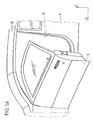
図5Aに、側方からみた自動車の車両構造(車体K)の一部分を示す。車体Kは、自動車の屋根部Dとともに、乗員が自動車内に入るためのドア開口部Oを形成している。変位可能または偏向位置調節可能なサイドドアSの形態の自動車構成部品が、ドア開口部Oを閉じるために回動可能に設けられており、図5Aには、その半開位置が示されている。自動車のサイドドアSを車両構造Kから当該半開位置にまでしか回動させない場合として、例えば、この自動車の隣に別の車両が停まった場合が挙げられる。この場合、サイドドアSをより広く開こうとすると、その別の車両にぶつかる可能性がある。したがって、このとき、サイドドアSを当該半開位置で固定し、突風や歩行者の不意の接触によってそれ以上開かないようにすることが重要となる。これを解決するために、いわゆる「ロック装置」を自動車に設けることにより、サイドドアSを半開位置で固定することができる。 FIG. 5A shows a part of the vehicle structure (vehicle body K) of the automobile as viewed from the side. The vehicle body K, together with the roof portion D of the automobile, forms a door opening O for an occupant to enter the automobile. An automotive component in the form of a displaceable or deflectable adjustable side door S is pivotally provided to close the door opening O, and its half-open position is shown in FIG. 5A. As a case where the side door S of the automobile is rotated only from the vehicle structure K to the half-open position, for example, there is a case where another vehicle stops next to the automobile. In this case, if the side door S is opened more widely, it may hit another vehicle. Therefore, at this time, it is important to fix the side door S at the half-open position so that the side door S does not open further due to a gust of wind or a pedestrian's unexpected contact. In order to solve this, the side door S can be fixed at the half-open position by providing a so-called “lock device” in the automobile.
図5Bに示すように、上記の種類のロック装置は、自動車のサイドドアに限らず、例えば、自動車の後端側RでトランクルームLを閉じるために配置された後尾ドアまたはテールゲートHに設けられてもよい。さらなる実施可能な用途として、荷室の開閉体、エンジン室の開閉体(ボンネット)、スライドドア、調整可能なカーゴフロア、ブラインド、または自動車の構造ユニットに対して変位可能(偏向位置調節可能)な他の自動車構成部品が挙げられる。以下の説明では、特に、回動可能接続(ヒンジ接続)された自動車構成部品を用いるが、本発明のロック装置は、摺動可能な自動車構成部品も含めて偏向位置調節可能な自動車構成部品全般に適用することができる。 As shown in FIG. 5B, the above-described type of locking device is not limited to a side door of an automobile, and is provided, for example, at a rear door or tailgate H arranged to close a trunk room L on the rear end side R of the automobile. May be. Further possible applications include displacement of the cargo compartment opening / closing body, engine compartment opening / closing body (bonnet), sliding door, adjustable cargo floor, blinds, or automotive structural units (adjustable deflection position) Other automotive components are listed. In the following description, in particular, a vehicle component having a pivotable connection (hinge connection) is used. However, the locking device of the present invention is a vehicle component that can adjust the deflection position, including a slidable vehicle component. Can be applied to.
図6Aは、偏向位置調節可能な自動車構成部品、例えば、図5Aに示すサイドドア、図5Bに示す後尾ドア、スライドドアなどを途中の偏向位置で固定するロック装置の第1実施形態を示す断面図である。 FIG. 6A is a cross-sectional view showing a first embodiment of a locking device for fixing a vehicle component that can adjust a deflection position, for example, a side door shown in FIG. 5A, a rear door shown in FIG. FIG.
ロック装置は、ハウジング下部51およびハウジング上部52を有する制動装置5を備えており、これらハウジング下部51およびハウジング上部52は、適切な取付手段、例えば、ねじやナットによって互いに連結されている。ハウジング51,52には、対向する摩擦領域10,20を介して互いに係合可能な2つの摩擦要素1,2が、制動部材として設けられている。これら摩擦領域10,20が係合することにより、(静止)摩擦が働き、偏向位置調節可能な自動車構成部品を途中の連続的に可変な偏向位置で固定することができる。
The locking device comprises a
第1摩擦要素1は、ハウジング51,52の内壁の一部、特に、ハウジング下部51の内壁の一部に形成されている。内壁の当該一部は、ハウジング軸心Aを中心とする回転対称で、かつ、ハウジング下部51のハウジング底部に向かって先細りとなる円錐面状に形成されて、第1摩擦要素の摩擦領域10を画定または形成している。つまり、第1摩擦要素1は、その摩擦領域10(ハウジングの軸心Aを中心とする回転対称で、円錐テーパ状である)がハウジング51,52の内周壁と一体的に形成されていることにより、ハウジングに固定されている。変形例として、ハウジングに対する第1摩擦要素の固定は、例えば、ハウジング内部の内壁と別体の摩擦要素を、ハウジング内部に固定することで行ってもよい。
The first friction element 1 is formed on a part of the inner walls of the
(ディスク状の)第2摩擦要素2は、トルク伝達可能にシャフト3に取り付けられている。シャフト3は、その2つの端部31,32を介して、ハウジング51,52の対応する軸受53,54に回転自在に取り付けられており、その回動軸心Aは、第1摩擦要素1の回転対称軸であるハウジング軸心と合致する。さらに、第2摩擦要素2は、第1摩擦要素1と同様に、摩擦領域の構造を除いて前記軸心Aを中心として実質的に回転対称状であり、かつ、ハウジング下部51内のハウジング底部に向かって先細りに形成されている。第2摩擦要素2は、このようにして円錐状の摩擦領域20を外周に形成しており、この摩擦領域20は、第1摩擦要素1の円錐状の摩擦領域10に対向し、これに係合することで摩擦固定を行うことができる。
The second friction element 2 (disc-shaped) is attached to the
2つの摩擦要素1,2の摩擦領域10,20が互いに係合して摩擦固定を行うように、ばねの形態の弾性要素4、より具体的には、圧縮ばねとして形成されたラップスプリング(コイルばね)が設けられている。この弾性要素4は、シャフト3を取り囲んでおり、その一端がシャフト3の大径端部32に支持され、他端が第2摩擦要素2に支持されている。これにより、第2摩擦要素2が第1摩擦要素1に対して付勢され、これらの2つの摩擦領域10,20が互いに係合する。すなわち、予圧を付与された弾性要素4による力または予圧が、シャフト3またはその軸心Aに沿った方向Rに作用することにより、第2摩擦要素2が当該方向Rに沿って第1摩擦要素1に付勢される。
An elastic element 4 in the form of a spring, more specifically a lap spring (coil) formed as a compression spring, so that the
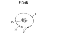
第2摩擦要素2は、その形状係合部25(図6Bおよび6C)とシャフト3の形状係合部33(図6A)とにより、シャフト3と共に回転するようにして当該シャフト3に取り付けられている。形状係合部25,33は、第2摩擦要素2がシャフト3の軸心A(およびこれに合致するハウジングの軸心)に沿って軸方向に動けるように互いに係合している。これにより、シャフト3に取り付けられた第2摩擦要素2は、弾性要素4の予圧作用方向Rに沿って軸方向に移動可能に第1摩擦要素1の摩擦領域10と所定の態様で係合することが可能となる。詳細な実施形態では、形状係合部25,33は、例えば、溝−弾性体接続を形成しており、シャフト軸心Aに沿って延びる、第2摩擦要素に設けられた溝25と、シャフト3から溝25に向かって外方に突出する、当該溝25に対応する突起状の弾性体33とを含む。
The
シャフト3から外方に突出した弾性体の形態の形状係合部33が、第2摩擦要素2の溝の形態の対応する形状係合部25と係合することにより、第2摩擦要素2は、相対回転不能にシャフト3に(任意で回動角度方向の遊びがあってもよい)取り付けられるとともに、弾性要素4の予圧の作用により軸心Aに沿った限定的な移動が可能となる。これにより、第2摩擦要素2の移動範囲には限界(最大限)が設定され、当該第2摩擦要素2の摩擦領域20が第1摩擦要素1の対応する摩擦領域10に圧接する。
When the
第2摩擦要素2は、上述したように軸方向に移動可能に取り付けられているので、弾性要素4の予圧の作用により、(自動的に)運動することができる。よって、第2摩擦要素2は、ロック装置の長期間の動作およびこれに起因する摩耗にもかかわらず、常に第1摩擦要素1の対応する摩擦領域10に所定の形態で係合することが可能になる。つまり、この自動的な追従運動は、弾性要素4の予圧の作用によって第2摩擦要素2がシャフト3に沿って軸方向に移動できることにより実現される。
Since the
2つの摩擦要素1,2の摩擦領域10,20の材料は、弾性要素4の予圧の作用によって当該摩擦領域10,20が互いに係合する際に十分に大きい静止摩擦力を生じるように選択される。これは、車両構造に対して途中まで偏向位置調節された自動車構成部品を、その途中の偏向位置でロック装置により固定できるようにするためである。これら2つの摩擦領域10,20の適切な材料の組合せについては、既に前述したとおりである。この例では、2つの摩擦領域10,20は、それぞれ、POM(ポリオキシメチレン)から作製されている。
The material of the
ロック装置は、偏向位置調節された自動車構成部品を確実に固定可能なだけでなく、当該自動車構成部品の円滑な偏向位置調節運動も可能にする。つまり、摩擦要素1,2の2つの摩擦領域10,20を相対的に運動させた際に働く当該摩擦領域10,20間の摩擦力を、できる限り小さくする必要がある。すなわち、2つの摩擦領域10,20が相対的に運動する際に当該摩擦領域10,20間に働く動摩擦力は、停止位置において弾性要素4が第2摩擦要素2を第1摩擦要素1に付勢する際に当該摩擦領域10,20間に働く静止摩擦力よりも遥かに小さくなり、好ましくは、大幅に小さくなる。
The locking device not only can securely fix the vehicle component that is adjusted in deflection position, but also enables smooth deflection position adjustment movement of the vehicle component. In other words, it is necessary to reduce the frictional force between the
相対回転不能にシャフト3に取り付けられた第2摩擦要素2は、対応する自動車構成部品の偏向位置調節運動に応じて運動する。この運動は、ロック装置の固定対象である当該自動車構成部品、例えば、車両ドア、自動車のサイドドア、後尾ドアなどの偏向位置調節運動がシャフト3の軸心A周りの回転運動に伝達されるように、当該シャフト3と前記偏向位置調節可能な自動車構成部品とが接続されることによって達成される。これを実現するにあたって、シャフト3と偏向位置調節可能な自動車構成部品とは、当該自動車構成部品が回動する回動軸心上で互いに直接接続されていてもよいし、または自動車構成部品の偏向位置調節運動をシャフトの回転運動に伝達する伝動機構が、当該シャフト3の上流に配設されてもよい。当該伝動機構は、例えば、特定比率の変速(第2摩擦要素の速度を上昇させるため)を行うか、例えば、シャフト3周りの偏向位置調節を行う。
The
このようにして、第2摩擦要素2は、シャフト3を介して、車両ドアなどの対応する偏向位置調節可能な自動車構成部品に接続され、当該自動車構成部品の偏向位置調節運動により、シャフト3の回転運動が生じる。
In this way, the
他方、第1摩擦要素1は、シャフト3と共に回転しないように、車両構造に固定される必要がある。これは、特に、内壁に摩擦領域10が形成された第1摩擦要素1を有するハウジング5を、車両構造側、例えば、ロック装置が取り付けられる車両ドアのフレームに設置することで達成できる。
On the other hand, the first friction element 1 needs to be fixed to the vehicle structure so as not to rotate with the
つまり、ロック装置が取り付けられる偏向位置調節可能な自動車構成部品が偏向位置調節運動を行うことにより、シャフト3を介して、第2摩擦要素2に、軸心Aを中心として第1摩擦要素1に対して回転する力が加わる。このとき、2つの円錐状の摩擦領域10,20は互いに摺動する。できる限り大きな静止摩擦力を確保すると同時に、自動車構成部品の偏向位置調節運動に抗して働く摩擦力が大き過ぎないように動摩擦の大きさを設定する必要がある。この目的は、2つの協働する摩擦領域10,20に用いられる材料を適切に選択することで達成できる。特に、静止摩擦力が動摩擦力(すべり摩擦力)よりも遥かに大きい材料の組合せ、特に、静止摩擦力が動摩擦力よりも数倍大きい材料の組合せを使用することで達成できる。
In other words, the deflecting position adjustable automobile component to which the locking device is attached performs the deflecting position adjusting motion, so that the
変形例として、または上記の構成に加えて、第2摩擦要素2が第1摩擦要素1に対して運動する際に2つの摩擦要素1,2の互いに対向する摩擦領域10,20の間に進入し、その摩擦力を低減する添加媒体または介在媒体(流動性の媒体)Zを設けてもよい。摩擦力を低減する潤滑剤として、適切なオイル、例えば、フロロシリコーン系オイルにエステル化合物を添加したものが用いられてもよい。特に、この構成は、POM製の摩擦領域10,20と組み合わせて用いられるのが好ましい。
As a variant or in addition to the above arrangement, when the
潤滑剤の形態の前記添加媒体または介在媒体Z、すなわち、流動性の材料で構成される前記添加媒体または介在媒体Zは、第2摩擦要素2の底側、すなわち、ハウジング底部に対向する面に少なくとも達する充填高さで、ハウジング下部51内に充填されている。
The additive medium or intervening medium Z in the form of a lubricant, that is, the additive medium or intervening medium Z composed of a fluid material is on the bottom side of the
第2摩擦要素2が第1摩擦要素1に対して相対運動、すなわち、回転運動を行う際に、十分な量の流動性の添加媒体または介在媒体Zが当該摩擦要素1,2の摩擦領域10,20間に進入して動摩擦を低減するように、案内用のチャネル21が、第2摩擦要素2の摩擦領域20に沿って設けられている(図6Bおよび図6Cを参照)。第2摩擦要素2の回転運動時には、案内用のチャネル21に沿って添加媒体または介在媒体Zが上昇し、2つの摩擦領域10,20間に進入する。
When the
第2摩擦要素2が停止状態にあるとき、すなわち、偏向位置調節される自動車構成部品がロック装置によってその偏向位置で固定されるとき、弾性要素4の予圧力によって互いに圧接する摩擦領域10,20間の領域から、前記添加媒体または介在媒体Zが押し出される。このため、添加媒体または介在媒体Zは、静止摩擦力に影響を及ぼさない。
When the
図6Bに示した第2摩擦要素2の実施形態において、案内用のチャネル21は、当該第2摩擦要素2の摩擦領域20において凹状構造の部位(溝または狭い通路)として形成されている。この凹状構造の部位は、シャフト3またはその軸心に実質的に沿って延在しているが、摩擦領域20の傾きに合わせて傾いている。
In the embodiment of the
図6Cに示す変形例において、第2摩擦要素2の摩擦領域20は、このディスク状の摩擦要素2の円周方向に沿って並んだ複数の球面部位で構成されている。例えば、これらの各球面部位の球面半径rbは、当該複数の球面部位が並んだ全体としての円形軌道の半径roよりも短い。このようにして、前記流動性の添加媒体または介在媒体を案内する案内用のチャネル21が、複数の球面部位が互いに隣接し合う箇所に形成されている。
In the modification shown in FIG. 6C, the
好ましくは、添加媒体Zの種類および量は、第2摩擦要素2ができる限り浮き上がらないように、かつ、前述のとおり、摩擦要素1,2が互いに接した状態においてこれらの摩擦領域の空間から押し出されるように選択される。これにより、停止状態での静止摩擦が確保される。
Preferably, the kind and amount of the additive medium Z are pushed out of the space of these friction regions so that the
上記をまとめると、図6A〜図6Cの構成により、以下のことが実現できる。ロック装置が取り付けられた自動車構成部品、例えば、車両ドアなどを変位させる偏向位置調節運動が終了すると、シャフト3はそれ以上回転せず、第2摩擦要素2が第1摩擦要素1に対向して停止することにより、摩擦領域10,20が相互に圧接する。このとき、弾性要素4の予圧力により、2つの摩擦領域10,20間に存在する介在媒体Zが、少なくとも摩擦領域10,20が互いに直接圧接する箇所から押し出される。介在媒体Zを押し出すのに必要な短い移行時間を経て、2つの摩擦領域10,20間に増大した(介在媒体Zが存在しない状態の)静止摩擦力が生じる。
In summary, the following can be realized by the configurations of FIGS. 6A to 6C. When the deflection position adjustment movement for displacing the automobile component to which the locking device is attached, for example, the vehicle door, is finished, the
対応する自動車構成部品を再び動かす(例えば、さらなる偏向位置調節を行うため、または開始位置にまで回動させるため)には、まず、ロック装置の摩擦領域10,20間の静止摩擦力を超えなければならない。第2摩擦要素2およびその摩擦領域20が第1摩擦要素1およびその摩擦領域10に対して運動する、すなわち、回転すると直ぐに、案内用のチャネル21を介して、介在媒体Zによって第1摩擦要素1の摩擦領域10が継続的に濡れた状態となる。これは、案内用のチャネル21が、第2摩擦要素2の回転運動時に第1摩擦要素1の摩擦領域の全体を徐々に通過することで確実に達成される。その後、第2摩擦要素2の摩擦領域20が介在媒体Z上を摺動することにより、第2摩擦要素2の摩擦領域20と第1摩擦要素1の摩擦領域10との間の動摩擦が低減される。
In order to move the corresponding car component again (for example to make further deflection position adjustments or to turn to the starting position), the static friction force between the
以上のように、摩擦要素1,2の形態の2つの制動部材を含む第1制動装置を備えた前述のロック装置により、偏向位置調節可能な自動車構成部品、例えば、サイドドア、後尾ドアなどを、ある偏向位置に固定することができる。これにより、例えば、突風や、ドアとの不意の接触によるそれ以上の偏向運動を防ぐことができる。また、当該自動車の周囲に存在する障害物、例えば、別の自動車、壁、街灯との衝突を防ぐことができる。
As described above, the above-mentioned locking device including the first braking device including the two braking members in the form of the
ロック装置の制動作用は、自動車の車両ドアに対して十分に大きい力を与えることで解除することができる。これは、ロック装置、特に、制動装置に対してモーメントをかけることにより、摩擦要素の形態の2つの制動部材1,2の間の制動係合(静止摩擦)が解除され、当該2つの制動部材が互いに動摩擦状態(すべり摩擦状態)で移動可能(回転可能)となることで達成される。
The braking action of the locking device can be released by applying a sufficiently large force to the vehicle door of the automobile. This is because the braking engagement (static friction) between the two
このようなロック装置であっても、偏向位置調節可能な自動車構成部品、特に、自動車の車両ドアに力を与える際に、障害物の存在を見落とすか、またはドアにかける力を誤ることで、当該自動車構成部品、特に、自動車の車両ドアと周囲に存在する障害物とが衝突する可能性がある。 Even with such a locking device, when applying force to a vehicle component that can adjust the deflection position, in particular, the vehicle door of the vehicle, the presence of an obstacle is overlooked or the force applied to the door is mistaken, There is a possibility of collision between the automobile component parts, in particular, the vehicle door of the automobile and obstacles existing around the automobile door.
上述のロック装置を改善するものとして、図1に、例えば図6A〜図6Cに示す構造の制動装置5が組み込まれた自動車の車両ドアであって、(任意の)追加の構成品として、制動モジュール6を備えるものを示す。
As an improvement to the locking device described above, FIG. 1 is a vehicle door of a motor vehicle incorporating a
追加の制動モジュール6の構造を、図2〜図4Bを参照しながら以下で説明する。制動モジュール6は、電気で駆動および/または電気で動作可能なアクチュエータを含み、このアクチュエータは、対応する自動車の車両ドア(サイドドアS)のドア構造T内に配設されたセンサN、例えば、近接センサに(電気的または光学的に)接続されている。
The structure of the
図1に概略的に示すセンサNは、自動車の車両ドアSの周囲の状態を監視することにより、外側に存在する障害物に当該ドアが接近しつつあるか否かを検出する。センサNは、出力信号(センサ信号)を生成し、この出力信号は判定部、例えば、ドア制御部Gに送信され、そこで評価される。センサ信号の評価に基づき、周囲に存在する障害物とドアとの衝突のリスクを判定部(ドア制御部G)が認識すると、当該判定部は、アクチュエータすなわち追加の制御モジュール6を起動させる。このようにして起動されたアクチュエータすなわち追加の制動モジュール6が、車両ドアSの実際の運動を停止させる制御力または制御モーメントを発生させる。これにより、センサNが認識した障害物との衝突を回避することができる。この目的のため、ドア制御部Gの形態の判定部は、センサNと追加の制動モジュール6との間に設けられる。
The sensor N schematically shown in FIG. 1 detects whether or not the door is approaching an obstacle existing outside by monitoring the state around the vehicle door S of the automobile. The sensor N generates an output signal (sensor signal), and this output signal is transmitted to a determination unit, for example, the door control unit G, where it is evaluated. When the determination unit (door control unit G) recognizes the risk of a collision between an obstacle existing in the vicinity and the door based on the evaluation of the sensor signal, the determination unit activates the actuator, that is, the
図1に示す第1制動装置5および追加の制動モジュール6を備えたロック装置の詳細を、図2〜図4B、主に、追加の制動モジュール6の組込み構成を示す図を参照しながら以下で説明する。第1制動装置5は、基本的に、図6A〜図6Cを参照して説明した構造を有する。
Details of the locking device provided with the
ただし、第1制動装置5の利用可能な実施形態は、図6A〜図6Cの実施形態に限定されない。重要なのは、ロック装置が、偏向位置調節可能な自動車構成部品、特に、自動車の車両ドアをある偏向位置(変位位置)に固定することができ、かつ、この固定作用を、偏向位置調節可能な自動車構成部品をさらに変位させることで解除できる第1制動装置5を備えているということである。
However, the embodiment which can utilize the
すなわち、ロック装置の第1制動装置5の機能は、偏向位置調節可能な自動車構成部品を、ある偏向位置(変位位置)に固定してその位置を停止位置とすることであり、追加の制動モジュール6の機能は、開閉体の周囲に存在する障害物に衝突するリスクが存在する場合、偏向位置調節可能な自動車構成部品の実際の運動を制動し、特には、運動を停止させることである。
In other words, the function of the
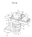
図2、図3A、図3B、図4Aおよび図4Bに、第1制動装置5、追加の制動モジュール6およびドアヒンジの構成品を備える、図1のロック装置を示す。当該ドアヒンジの構成品には、自動車の車両ドアに設けられる支持要素100(ドアヒンジ用の山形材)と、外側ボディ(例えば、車両構造、車体Kなど)側に設けられ、当該支持要素100に接続されることでヒンジを形成する保持部材200(接続用の山形材)が含まれる。ヒンジは、自動車の前側のサイドドアに設けられる場合、Aピラーに配置され、自動車の後側のサイドドアに設けられる場合、Bピラーに配置される。
2, 3A, 3B, 4A and 4B show the locking device of FIG. 1 with a
詳細には、図4Aに示すように、車両ドア側の支持要素100はヒンジ部106を有しており、ヒンジ部106は、ヒンジ300を介して、前記外側ボディ側の保持部材200とヒンジ接続を形成する。
Specifically, as shown in FIG. 4A, the vehicle door
さらに、車両ドア側の支持要素100には、第1制動装置5と追加の制動モジュール6とを保持するための少なくとも1つの保持部102が設けられている。保持部102は互いに反対方向を向く2つの表面102a,102bを有しており、表面102aには第1制動装置5が配置されており、表面102bには追加の制動モジュール6が配置されている。このため、取付部として、例えば、取付用の開口126が保持部102に設けられている。変形例として、第1制動装置5と追加の制動モジュール6とに対して別体に保持部を設けてもよく、この場合、第1制動装置5は、さらに、別体に形成された組み込みユニットとして車両ドア側の支持要素100と一体化された支持部104(図3B)によって支持される。
Furthermore, the
第1制動装置5と追加の制動モジュール6は、いずれも、2つの部材で構成されるハウジング51,52、61,62を有しており、各ハウジングは、第1ハウジング部(ハウジング下部)51,61および第2ハウジング部(ハウジング上部)52,62で構成される。
Each of the
第1制動装置5のハウジングのハウジング部51,52は、掛け止め要素の形態の形状係合要素55,56を介してバヨネット式に互いに接続されている。追加の制動モジュール6のハウジングのハウジング部61,62は、ねじ接続部65,66(図2、図3Aおよび図3B)を介して互いに取付けられている。
The
ロック装置の内部を通るシャフト3と相互作用するラックZは、例えば、シャフト3に設けられた伝動要素(ギヤ)を介して当該シャフト3とを動作させる。これにより、シャフト3は、図4Aおよび図4Bに示すように、自動車の車両ドアを変位させることで回転する。
The rack Z that interacts with the
また、図4Aおよび図4Bにおいて、ロック装置の第1制動装置5は、図6A〜図6Cを参照しながら詳細に前述した制動装置と同じ制動原理に基づいて動作し、かつ、摩擦要素の形態の対応する制動部材1,2、および2つの摩擦要素1,2を互いに付勢する圧縮ばねの形態の弾性要素4を含んでいてもよい。
4A and 4B, the
特に図3A、図3B、図4Aおよび図4Bから明らかなように、追加の制動モジュール6は、その構成品として、(ハウジング部61,62内に設けられた)アクチュエータ7を含む。同図の実施形態において、アクチュエータ7の形態は、駆動軸70を駆動する電気モータ駆動部である。
As can be seen in particular from FIGS. 3A, 3B, 4A and 4B, the
電気モータ駆動部の形態のアクチュエータ7は、電気的に動作されるアクチュエータであり、(例えば、形状固定または摩擦固定を介して)機械的な制動力を生成する。アクチュエータ7の形態は、電動式駆動部の形態の他にも、例えば、さらなる電気手段を介して動作されることで制動力を生成するリフティングマグネットまたはアクチュエータであってもよい。
The
アクチュエータ7が生成する出力または対応する出力モーメントを機械的に作用する制動力に変換するために、アクチュエータ7は、接続機構8,80a,80b(図3B)を介して、ラップスプリングの形態の機械式の制動手段9に接続されている。このラップスプリングは、対応する偏向位置調節可能な自動車構成部品に動作可能に接続されたシャフト3の一部を形成する構成部材である、シャフト部35に巻き付けられている。
In order to convert the output generated by the
アクチュエータ7の上記接続は、当該アクチュエータ7が駆動軸70を介して可撓性の牽引手段8に作用するように行われており、可撓性の牽引手段8の一部81が、アクチュエータ7の駆動軸70に巻き付けられている。なお、この実施形態において、可撓性の牽引手段8はロープである。これにより、アクチュエータ7を動作させることで、特に、アクチュエータ7を形成する電気モータに電流を供給することで、牽引力が、駆動軸70上に環状に形成されたまたは巻き付けられた可撓性の牽引手段8の一部81を介して、その可撓性の牽引手段8に作用する。
The connection of the
可撓性の牽引手段8は、制御レバー85を動作させるためのさらなる一部82を有している。制御レバー85はラップスプリング9の一弾性端部91に固定されており、特には、当該制御レバー85にラップスプリング9の一弾性端部91が挿入されている。ラップスプリング9の他の弾性端部92が、図示されていない拘束部(Anschlag)に支持され、かつ、一弾性端部91が、駆動軸70、可撓性の牽引手段8および制御レバー85を介してアクチュエータ7に接続されていることにより、当該アクチュエータ7が動作されることでラップスプリング9が収縮する。このようにして、摩擦係合による制動力が、シャフトのシャフト部35、つまり、シャフト3に伝達される。これにより、シャフト3の速度が低減し、対応する開閉体(自動車の車両ドア)が摩擦係合を介して固定され、さらなる運動が妨げられる。
The flexible traction means 8 has a
ロープの形態の可撓性の牽引手段8は、そのさらなる一部82が制御レバー85の偏向部位86に巻き付けられており、かつ、ラップスプリングの形態の制動手段9とアクチュエータ7との間において、延在方向に対して交差する方向に互いに離間した2つの長手方向の部位80a,80bを有する。つまり、可撓性の牽引手段8は、まず、その長手方向の第1部位80aが制御レバー85に向かって案内され、その長手方向の第2部位80bがアクチュエータ7の方向に戻ってくる。
The flexible traction means 8 in the form of a rope has its
また、可撓性の牽引手段8の一部81は、駆動軸70に配置された固定ドラムの形態の固定要素83により、アクチュエータ7の当該駆動軸70に巻き付けられている。制御レバー85で偏向して戻ってくる長手方向の第2部位80bは、保持要素84によって(アクチュエータ7の近傍に)保持されて固定されるが、駆動軸70と共に回転することはない。
A
牽引手段8を介してアクチュエータ7から制動手段9に力を伝達させる際、牽引手段8の少なくとも2つの部位80a,80bを、ラップスプリングの形態の制動手段9とアクチュエータ7との間の少なくとも一部に延在させることにより、滑車の原理でアクチュエータ7から制動手段9への伝動が行われる。
When transmitting the force from the
追加の制動モジュール6は、所望の構成に応じて、ロック装置の第1制動装置5と任意で組み合わせることが可能な(すなわち、第1制動装置5に対して脱着可能に構成された)モジュールである。
The
これが可能なのは、当該追加の制動モジュール6が、第1制動装置5と独立して保持部102に固定できるように構成されているからである。すなわち、この実施形態では、第1制動装置5が配置される保持部102の表面(側面)102aと反対側の表面(側面)102bに、追加の制動モジュール6が配置される。
This is possible because the
また、対応する偏向位置調節可能な自動車構成部品に接続されるシャフト3は、追加の制動モジュール6の内部を延びるシャフト部(第1シャフト部)35と、第1制動装置5の内部を延びるシャフト部(第2シャフト部)30とを有しており、かつ、シャフト部30に、特に、シャフト部30の、追加の制動モジュール6に面する端部に、インターフェース領域34(図4A)を有している。この実施形態において、インターフェース領域34は形状係合部の形態の接続部であり、かつ、他方のシャフト部35にも形状係合部の形態の接続部36が設けられており、これら2つの接続部を介して、2つのシャフト部30,35の接続が行われる。
In addition, the
すなわち、追加の制動モジュール6は、対応するシャフト部35を用いることで、インターフェース34,36を介して任意で第1制動装置5、特に、シャフト部30と接続することができる。このようにして、シャフト部30,35は、偏向位置調節可能な自動車構成部品、特に、車両ドアに接続されるシャフト3の一部を形成する。
That is, the
前述したように、シャフト3は、ラックZの形態の伝動要素を介して、対応する車両ドアと相互作用する。特に、ロック装置の固定側部品である第1制動装置5に対応するシャフト部30が、ラックZの形態の伝動要素を介して、対応する車両ドアと相互作用する。この目的のために、ラックと係合するギヤ(ピニオン)が、シャフト部30に設けられてもよい。
As mentioned above, the
なお、制動モジュール6を追加しない場合、第1制動装置5を再構成する必要はない。すなわち、第1制動装置5と反対側の保持部102の表面102bに、追加の制動モジュール6を配置しないだけで済む。これに伴い、追加の制動モジュール6側のシャフト部35と第1制動装置5のシャフト部30との、インターフェース34,36を介した接続もなくなる。
If the
また、追加の制動モジュール6側のシャフト部35の、第1制動装置5と反対側の端部には、当該シャフト部35を位置決めするための軸受部38が設けられている。軸受部38は、第1制動装置5に配置されたシャフト部30のインターフェース領域34と同様の形状を有している。したがって、制動モジュール6を追加しない場合、第1制動装置5のシャフト部30のインターフェース領域34を、軸受部として用いてもよい。
Further, a bearing
また、シャフト3は、図6A〜図6Cを参照しながら前述した構成に基づき、ハウジング51,52内、特に、第1制動装置5のハウジング下部51内に位置決めされる。
The
図2〜図4Bには、アクチュエータ7が、自動車の対応する開閉体、特に、当該開閉体に接続されたシャフト3を、(接続機構8,85およびラップスプリング9を介して、)第1制動装置5の制動部材1,2と独立して制動する構成が示されている。もっとも、摩擦要素1,2の一方と、特に、第2摩擦要素2と、アクチュエータ7を相互作用させる適切な接続機構を設けてもよい。
2 to 4B, the
このような場合、アクチュエータ7が2つの摩擦要素1,2を互いに圧接させることで静止摩擦状態を作り出して、対応する制動力を発生させることにより、対応する開閉体(自動車の車両ドア)の変位運動を制動し、かつ防ぐことが可能になる。つまり、第2摩擦要素2に連結したシャフト3が減速することにより、シャフト3に接続された開閉体(自動車の車両ドア)も減速する。
In such a case, the
(電流を供給して)アクチュエータ7を起動させることによって自動車構成部品の変位運動を制動するという構成の一実施形態において、電流は、特に、図1に示す自動車の車両ドアに対し、限られた(短い)時間、例えば、数秒供給される。アクチュエータ7、接続機構8,85および対応する制動手段9が自己ロック式の構成でない場合には、アクチュエータ7の動作が終了すると、その制動作用も終わる。したがって、ロック装置が生成する静止摩擦力を超える力を与えれば、対応する自動車構成部品(例えば、図1に示す自動車の車両ドア)のさらなる偏向運動は可能である。しかしながら、(電流を供給して)アクチュエータ7を起動させて、偏向位置調節可能な自動車構成部品を制動かつ固定することにより、車両の乗員は、障害物が周囲に存在していることを把握できるので、十分な注意を払いながら自動車構成部品のさらなる変位を実行することができる。
In one embodiment of the arrangement of braking the displacement movement of the automobile component by activating the actuator 7 (supplying current), the current is limited, especially for the vehicle door of the automobile shown in FIG. Provided for (short) time, eg several seconds. When the
一実施形態において、起動の制御に利用されるセンサN(図1を参照)は、アクチュエータ7の最初の動作後、アクチュエータ7のその次の動作後までの短い時間、トリガしないように構成されている。これにより、乗員は、障害物が存在していても、例えば、当該障害物に軽く接触することにより、対応する自動車構成部品の偏向位置調節運動を実行することができる。また、センサNを利用したアクチュエータ7の最初の起動後において、対応する自動車構成部品が障害物にさらに近付き、これにより、衝突の危険性が著しく増した場合にのみアクチュエータ7の次の起動が生じるように設定してもよい。この設定は、障害物が新たな位置に移動されたかまたは自己移動した場合にも適用できる。
In one embodiment, the sensor N (see FIG. 1) used to control activation is configured not to trigger for a short time after the first operation of the
あるいは、アクチュエータ7および/または接続機構8,85および/または制動手段9を自己ロック式に構成し、これにより、アクチュエータ7の起動後の、アクチュエータ7が動作していないあいだも、特に、アクチュエータ7に電流が供給されていないあいだも制動作用が維持されるように設定してもよい。この場合、アクチュエータ7を反対方向に動作させることによって、制動作用を積極的に補償する必要があり、その目的のために、例えば、特定の制御要素を、自動車、特に、自動車の偏向位置調節可能な車両ドアの内側に設けてもよい。
Alternatively, the
上記で説明した実施形態の基本構成となるロック装置は、変位可能な自動車構成部品を、変位可能範囲内における変位によって到達した停止位置で固定するロック装置であって、少なくとも2つの制動部材(1,2)を含む制動装置(5)を備えており、前記少なくとも2つの制動部材(1,2)は、前記自動車構成部品(H,S)の停止位置において相互作用することで、前記自動車構成部品(H,S)を固定するための制動作用を生じるロック装置において、前記自動車構成部品(H,S)を固定するための、当該自動車構成部品(H,S)の変位運動を制動可能なアクチュエータ(7)が、前記制動装置(5)と選択的に組み合わせ可能に取り付けられており、前記アクチュエータ(7)は、前記変位可能な自動車構成部品(H,S)の変位運動によって運動可能な構成部材(35)に動作可能に接続され、かつ、前記構成部材(35)に対して作用することにより、前記制動装置(5)と独立して、前記変位可能な自動車構成部品(H,S)の変位運動を制動可能である。さらに、上記で説明した実施形態またはその変形例は、以下の態様1〜19を含む。The locking device as the basic configuration of the embodiment described above is a locking device that fixes a displaceable automobile component at a stop position reached by displacement within a displaceable range, and includes at least two braking members (1 , 2), and the at least two braking members (1, 2) interact with each other at a stop position of the automobile component (H, S), thereby In a locking device that generates a braking action for fixing the parts (H, S), the displacement movement of the automobile component (H, S) for fixing the automobile component (H, S) can be braked. An actuator (7) is mounted so as to be selectively combined with the braking device (5), and the actuator (7) is the displaceable automobile component (H, S). The displaceable motor vehicle is operatively connected to a component member (35) movable by a displacement movement and acts on the component member (35) so as to be independent of the braking device (5). The displacement movement of the component parts (H, S) can be braked. Furthermore, embodiment described above or its modification contains the following aspects 1-19.
(態様1)(Aspect 1)
前記変位調節可能な自動車構成部品(H,S)に解除力が与えられ、前記変位調節可能な自動車構成部品(H,S)と前記少なくとも2つの制動部材(1,2)とが相互作用することにより、当該少なくとも2つの制動部材(1,2)の互いの制動係合が解除可能であってもよい。 A release force is applied to the vehicle component (H, S) whose displacement can be adjusted, and the vehicle component (H, S) whose displacement can be adjusted interacts with the at least two braking members (1, 2). Accordingly, the brake engagement of the at least two brake members (1, 2) may be releasable.
(態様2)(Aspect 2)
前記制動装置(5)が配置される支持要素(100)を備えていてもよい。 A support element (100) on which the braking device (5) is arranged may be provided.
(態様3)
前記制動装置(5)が配置される支持要素(100)を備えており、前記支持要素(100)は、前記制動装置(5)に加えて、前記追加のモジュール(6)を保持可能であってもよい。
(Aspect 3)
The brake device (5) is provided with a support element (100) on which the support element (100) can hold the additional module (6) in addition to the brake device (5). May be.
(態様4)(Aspect 4)
前記アクチュエータ(7)が電動式の駆動部として構成されていてもよい。 The actuator (7) may be configured as an electric drive unit.
(態様5)(Aspect 5)
前記アクチュエータ(7)が、リフティングマグネットを含んでいてもよい。 The actuator (7) may include a lifting magnet.
(態様6)(Aspect 6)
前記アクチュエータ(7)に少なくとも1つのセンサ(N)が接続されており、当該少なくとも1つのセンサ(N)の出力信号に応じて、前記アクチュエータ(7)が起動されてもよい。 At least one sensor (N) may be connected to the actuator (7), and the actuator (7) may be activated in response to an output signal of the at least one sensor (N).
(態様7)(Aspect 7)
前記少なくとも1つのセンサ(N)が、前記変位可能な自動車構成部品に取り付けられていてもよい。 The at least one sensor (N) may be attached to the displaceable automobile component.
(態様8)(Aspect 8)
前記少なくとも1つのセンサ(N)が、前記変位可能な自動車構成部品の周囲を検出することにより、前記変位可能な自動車構成部品が障害物に近付くと、前記アクチュエータ(7)が起動されてもよい。 When the at least one sensor (N) detects the periphery of the displaceable vehicle component, the actuator (7) may be activated when the displaceable vehicle component approaches an obstacle. .
(態様9)(Aspect 9)
前記アクチュエータ(7)が、前記変位可能な自動車構成部品(H,S)に対する制動作用時に、前記制動装置(5)の前記少なくとも2つの制動部材(1,2)のいずれにも作用しないことにより、前記アクチュエータ(7)が、前記変位可能な自動車構成部品(H,S)の変位運動時に運動する構成部材(35)に対して、前記制動装置とは独立に作用するように接続されていてもよい。 The actuator (7) does not act on any of the at least two braking members (1, 2) of the braking device (5) during the braking action on the displaceable vehicle component (H, S). The actuator (7) is connected to the component member (35) that moves during the displacement movement of the displaceable automobile component (H, S) so as to act independently of the braking device. Also good.
(態様10)(Aspect 10)
さらに、前記変位可能な自動車構成部品(H,S)の変位運動によって回転するように当該自動車構成部品(H,S)に接続されたシャフト(3)を備えており、前記構成部材(35)が、前記シャフト(3)の一部である第1シャフト部として形成されていてもよい。 Furthermore, it comprises a shaft (3) connected to the automobile component (H, S) so as to rotate by the displacement movement of the displaceable vehicle component (H, S), and the component (35) However, you may form as a 1st shaft part which is a part of said shaft (3).
(態様11)(Aspect 11)
前記可撓性の牽引手段(8)が、前記アクチュエータ(7)によって動作可能な駆動軸(70)に巻き付けられていてもよい。 The flexible traction means (8) may be wound around a drive shaft (70) operable by the actuator (7).
(態様12)(Aspect 12)
前記可撓性の牽引手段(8)が、当該牽引手段(8)の一部(82)を介して、前記制動手段(9)と相互作用するものであってもよい。 The flexible traction means (8) may interact with the braking means (9) via a part (82) of the traction means (8).
(態様13)(Aspect 13)
前記可撓性の牽引手段(8)が、制御レバー(85)を介して、前記制動手段(9)と相互作用してもよい。 The flexible traction means (8) may interact with the braking means (9) via a control lever (85).
(態様14)(Aspect 14)
可撓性の牽引手段(8)は、その少なくとも2つの部位(80a,80b)が、前記制動手段(9)と前記アクチュエータ(7)との間の少なくとも一部において互いに離間するように巻かれていることにより、滑車の原理に基づく伝動を行うものであってもよい。 The flexible traction means (8) is wound such that at least two parts (80a, 80b) are separated from each other at least at a part between the braking means (9) and the actuator (7). Therefore, transmission based on the principle of the pulley may be performed.
(態様15)(Aspect 15)
前記機械式の制動手段(9)が、ラップスプリングで形成されていてもよい。 The mechanical braking means (9) may be formed of a wrap spring.
(態様16)(Aspect 16)
前記制動手段が、摩擦ウェッジで形成されていてもよい。 The braking means may be formed of a friction wedge.
(態様17)(Aspect 17)
前記制動装置(5)の前記少なくとも2つの制動部材(1,2)が、互いに圧接するように付勢されており、前記少なくとも2つの制動部材(1,2)のうちの少なくとも一つの制動部材(2)は、他の制動部材(1)に対する予圧が付与されており、この予圧が作用する方向に沿って追従運動可能に取り付けられていてもよい。 The at least two braking members (1, 2) of the braking device (5) are urged so as to come into pressure contact with each other, and at least one braking member of the at least two braking members (1, 2) In (2), a preload is applied to the other braking member (1), and the brake member may be attached so as to be able to follow along the direction in which the preload acts.
(態様18)(Aspect 18)
前記制動部材(1,2)同士が相対運動する際に、これらの互いに対向する摩擦領域(10,20)の間に進入する、流動性の添加媒体(Z)を前記制動装置(5)内に有していてもよい。 When the braking members (1, 2) move relative to each other, a fluid additive medium (Z) that enters between the friction regions (10, 20) facing each other is introduced into the braking device (5). You may have.
(態様19)(Aspect 19)
前記変位可能な自動車構成部品(H,S)が車両ドアとして形成されていてもよい。The displaceable automobile component (H, S) may be formed as a vehicle door.
さらに、上記実施形態に係るロック装置の組み立て方法は、上記実施形態に係る構成を備えたロック装置を組み立てることを含む。Furthermore, the method for assembling the lock device according to the above embodiment includes assembling the lock device having the configuration according to the above embodiment.
1,2 制動部材
5 制動装置
6 追加の制動モジュール
7 アクチュエータ
8,85 接続機構
9 制動手段
35 構成部材
H,S 変位可能な自動車構成部品
DESCRIPTION OF
Claims (13)
前記自動車構成部品(H,S)を固定するための、当該自動車構成部品(H,S)の変位運動を制動可能なアクチュエータ(7)が、前記制動装置(5)と選択的に組み合わせ可能に取り付けられており、
前記アクチュエータ(7)は、前記変位可能な自動車構成部品(H,S)の変位運動によって運動可能な構成部材(35)に動作可能に接続され、かつ、前記構成部材(35)に対して作用することにより、前記制動装置(5)と独立して、前記変位可能な自動車構成部品(H,S)の変位運動を制動可能であり、
前記自動車構成部品(H,S)を固定するための、当該自動車構成部品(H,S)の変位運動を制動可能なアクチュエータ(7)に接続するためのインターフェース(34)が、前記制動装置(5)に設けられている
ことを特徴とするロック装置。 A locking device for fixing a displaceable vehicle component at a plurality of intermediate stop positions reached by displacement of the vehicle component within a displaceable range between a fully open position and a fully closed position. And a braking device (5) including at least two braking members (1, 2), wherein the at least two braking members (1, 2) are arranged at intermediate stop positions of the automobile component (H, S). In the locking device that generates a braking action for fixing the vehicle component (H, S) to the intermediate stop position by interacting with
An actuator (7) that can brake the displacement motion of the automobile component (H, S) for fixing the automobile component (H, S) can be selectively combined with the braking device (5). Installed,
The actuator (7) is operatively connected to a component (35) movable by the displacement movement of the displaceable automobile component (H, S) and acts on the component (35). By doing so, it is possible to brake the displacement movement of the displaceable automobile components (H, S) independently of the braking device (5),
An interface (34) for connecting the displacement movement of the automobile component (H, S) to the actuator (7) capable of braking for fixing the automobile component (H, S) is provided in the braking device ( A locking device provided in 5).
a)少なくとも2つの制動部材(1,2)を含む制動装置(5)を作製する工程であって、前記少なくとも2つの制動部材(1,2)は、前記自動車構成部品(H,S)の各中間停止位置において相互作用することで、前記自動車構成部品(H,S)を前記中間停止位置に固定するための制動作用を生じ、また、当該制動装置(5)に解除力が与えられることで互いの制動係合が解除される、制動装置作製工程と、
b)追加の制動モジュール(6)を作製する工程であって、前記追加の制動モジュール(6)は、電気的に動作可能なアクチュエータ(7)と、前記自動車構成部品(H,S)の変位運動を制動するための、前記ロック装置の部品と前記アクチュエータ(7)との相互作用を介する接続機構(8,85)とを含み、前記自動車構成部品(H,S)を固定するための、当該自動車構成部品(H,S)の変位運動を制動可能な前記アクチュエータ(7)が、前記制動装置(5)と選択的に組み合わせ可能に取り付けられており、前記アクチュエータ(7)は、前記変位可能な自動車構成部品(H,S)の変位運動によって運動可能な構成部材(35)に動作可能に接続され、かつ、前記構成部材(35)に対して作用することにより、前記制動装置(5)と独立して、前記変位可能な自動車構成部品(H,S)の変位運動を制動可能である、制動モジュール作製工程と、
c)前記ロック装置を、前記制動装置(5)に加えて、追加の制動モジュール(6)を備える第1の装置として組み立てるか、または前記ロック装置を前記制動モジュールを備えない第2の装置として組み立てるかについて判断を行う工程と、
d)前記判断の結果に応じて、前記ロック装置の構成品として、前記制動装置(5)のみ、または前記制動装置(5)と前記追加の制動モジュール(6)との組合せを設ける工程であって、前記制動装置(5)が、前記自動車構成部品(H,S)を固定するための、当該自動車構成部品(H,S)の変位運動を制動可能な前記アクチュエータ(7)に接続するためのインターフェース(34)を有する装置である工程と、
を含むロック装置組立方法。 Method for assembling a locking device for fixing a displaceable vehicle component at a plurality of intermediate stop positions reached by displacement of said vehicle component within a displaceable range between a fully open position and a fully closed position Because
a) manufacturing a braking device (5) including at least two braking members (1, 2), wherein the at least two braking members (1, 2) By interacting at each intermediate stop position, a braking action for fixing the vehicle component (H, S) to the intermediate stop position is generated, and a release force is applied to the braking device (5). And a braking device manufacturing process in which mutual braking engagement is released,
b) Step of making an additional braking module (6), the additional braking module (6) comprising an electrically operable actuator (7) and displacement of the vehicle components (H, S) A connection mechanism (8, 85) for the purpose of braking movement, through the interaction between the parts of the locking device and the actuator (7), for fixing the vehicle components (H, S), The actuator (7) capable of braking the displacement movement of the automobile component (H, S) is attached so as to be selectively combined with the braking device (5), and the actuator (7) Operatively connected to a movable component (35) by displacement movement of the possible automotive components (H, S) and acting on said component (35) to (5) independently of said a displacement movement of the displaceable motor vehicle part (H, S) can brake, a brake module manufacturing process,
c) assembling the locking device as a first device with an additional braking module (6) in addition to the braking device (5) or as a second device without the braking module A process of determining whether to assemble, and
d) A step of providing only the braking device (5) or a combination of the braking device (5) and the additional braking module (6) as a component of the locking device according to the result of the determination. The brake device (5) is connected to the actuator (7) capable of braking the displacement movement of the vehicle component (H, S) for fixing the vehicle component (H, S). A process having an interface (34) of:
A method of assembling the lock device.
Applications Claiming Priority (2)
| Application Number | Priority Date | Filing Date | Title |
|---|---|---|---|
| DE102009041498.3 | 2009-09-14 | ||
| DE102009041498A DE102009041498A1 (en) | 2009-09-14 | 2009-09-14 | Locking device for locking a motor vehicle part |
Publications (3)
| Publication Number | Publication Date |
|---|---|
| JP2011058353A JP2011058353A (en) | 2011-03-24 |
| JP2011058353A5 JP2011058353A5 (en) | 2013-07-25 |
| JP5793285B2 true JP5793285B2 (en) | 2015-10-14 |
Family
ID=43603357
Family Applications (1)
| Application Number | Title | Priority Date | Filing Date |
|---|---|---|---|
| JP2010204918A Expired - Fee Related JP5793285B2 (en) | 2009-09-14 | 2010-09-13 | Locking device for fixing automotive components |
Country Status (4)
| Country | Link |
|---|---|
| US (1) | US8596424B2 (en) |
| JP (1) | JP5793285B2 (en) |
| DE (1) | DE102009041498A1 (en) |
| FR (1) | FR2950099B1 (en) |
Families Citing this family (6)
| Publication number | Priority date | Publication date | Assignee | Title |
|---|---|---|---|---|
| JP5578154B2 (en) * | 2011-10-25 | 2014-08-27 | アイシン精機株式会社 | Vehicle door opening and closing device |
| RU2660093C1 (en) | 2015-04-09 | 2018-07-04 | Малтиматик, Инк. | Door system of vehicle with smooth door check |
| DE102016113353A1 (en) * | 2016-07-20 | 2018-01-25 | Brose Fahrzeugteile Gmbh & Co. Kg, Bamberg | Drive arrangement of a closure element arrangement |
| KR102485333B1 (en) * | 2016-12-16 | 2023-01-05 | 현대자동차주식회사 | Gate lifter for vehicle |
| US20190112849A1 (en) * | 2017-10-16 | 2019-04-18 | Magna Closures Inc. | Power-operated variable force door check mechanism for a vehicular closure system |
| JP7304114B2 (en) * | 2019-12-06 | 2023-07-06 | 株式会社アイシン | vehicle door stop |
Family Cites Families (26)
| Publication number | Priority date | Publication date | Assignee | Title |
|---|---|---|---|---|
| US2893506A (en) * | 1958-03-11 | 1959-07-07 | Nat Pneumatic Co Inc | Door controlling linkage |
| US3061362A (en) * | 1958-11-01 | 1962-10-30 | Minoru Okada | Vacuum-actuated, remote control apparatus for opening and closing motor vehicle doors |
| JPS60118028A (en) | 1983-11-30 | 1985-06-25 | 新電元工業株式会社 | Power source for monitor |
| DE3434905A1 (en) * | 1984-09-22 | 1986-04-03 | SWF Auto-Electric GmbH, 7120 Bietigheim-Bissingen | DRIVE UNIT, ESPECIALLY FOR ADJUSTING WINDOW WINDOWS, SLIDING ROOFS, SEATS AND SIMILAR MOTOR VEHICLE PARTS |
| US4628568A (en) * | 1985-08-01 | 1986-12-16 | General Motors Corporation | Friction type hold open mechanism |
| US4995194A (en) * | 1990-03-27 | 1991-02-26 | Yale Security Inc. | Power-assist door closer |
| DE19537816A1 (en) * | 1995-10-11 | 1997-04-17 | Scharwaechter Gmbh Co Kg | Stepless auxiliary motor vehicle door lock |
| DE19800679C2 (en) * | 1998-01-10 | 2002-08-08 | Scharwaechter Ed Gmbh | Actuator for a parking brake |
| US6125768A (en) * | 1998-10-14 | 2000-10-03 | Westinghouse Air Brake Company | Door system for transit vehicle |
| JP2001227237A (en) * | 2000-02-17 | 2001-08-24 | Tok Bearing Co Ltd | Damping mechanism |
| GB0003686D0 (en) * | 2000-02-18 | 2000-04-05 | Meritor Light Vehicle Sys Ltd | Actuator assemblies |
| US6536814B2 (en) * | 2000-03-08 | 2003-03-25 | Brose Schliessysteme Gmbh | Motor vehicle door lock with a controlled actuating element |
| US6459223B2 (en) * | 2000-05-03 | 2002-10-01 | Robert Bosch Gmbh | Motor vehicle door lock and process for its control |
| DE10120832B4 (en) * | 2001-04-27 | 2006-03-02 | Rk Rose + Krieger Gmbh & Co Kg Verbindungs- Und Positioniersysteme | Electromotive actuator |
| US6848759B2 (en) * | 2002-04-03 | 2005-02-01 | Illinois Tool Works Inc. | Self-closing slide mechanism with damping |
| DE10214670B4 (en) * | 2002-04-03 | 2014-01-23 | Knorr-Bremse Systeme für Schienenfahrzeuge GmbH | Brake application device with electrically operated wear adjuster |
| DE10214669B4 (en) * | 2002-04-03 | 2014-01-23 | Knorr-Bremse Systeme für Schienenfahrzeuge GmbH | Method and device for controlling an electrically operated wear adjustment device |
| DE10331466A1 (en) * | 2003-07-11 | 2005-02-10 | Robert Bosch Gmbh | locking device |
| JP4512868B2 (en) * | 2004-03-31 | 2010-07-28 | 日立オートモティブシステムズ株式会社 | Electric brake device |
| JP2006290296A (en) * | 2005-04-14 | 2006-10-26 | Ntn Corp | Door checker |
| DE102005055084B4 (en) * | 2005-09-29 | 2017-02-09 | Robert Bosch Gmbh | Combined service and parking brake device |
| JP4389897B2 (en) | 2006-05-30 | 2009-12-24 | 三菱自動車工業株式会社 | Automobile door opening movement regulating device |
| GB0713116D0 (en) | 2007-07-06 | 2007-08-15 | Therapeutics Ltd E | Treatment of melanoma |
| DE202007009824U1 (en) * | 2007-07-10 | 2008-11-20 | Brose Fahrzeugteile Gmbh & Co. Kommanditgesellschaft, Coburg | Locking device of a motor vehicle for locking a displaceable motor vehicle part |
| DE202008015420U1 (en) * | 2008-11-21 | 2009-02-19 | Brose Fahrzeugteile Gmbh & Co. Kommanditgesellschaft, Coburg | Device for stepless locking of a motor vehicle door |
| DE102009041499A1 (en) * | 2009-09-14 | 2011-03-24 | Brose Fahrzeugteile Gmbh & Co. Kommanditgesellschaft, Coburg | Locking device for locking a motor vehicle part |
-
2009
- 2009-09-14 DE DE102009041498A patent/DE102009041498A1/en not_active Withdrawn
-
2010
- 2010-09-10 FR FR1057229A patent/FR2950099B1/en not_active Expired - Fee Related
- 2010-09-13 JP JP2010204918A patent/JP5793285B2/en not_active Expired - Fee Related
- 2010-09-13 US US12/881,117 patent/US8596424B2/en not_active Expired - Fee Related
Also Published As
| Publication number | Publication date |
|---|---|
| FR2950099A1 (en) | 2011-03-18 |
| DE102009041498A1 (en) | 2011-03-24 |
| US20110061199A1 (en) | 2011-03-17 |
| US8596424B2 (en) | 2013-12-03 |
| FR2950099B1 (en) | 2015-06-05 |
| JP2011058353A (en) | 2011-03-24 |
Similar Documents
| Publication | Publication Date | Title |
|---|---|---|
| JP5514055B2 (en) | Locking device for fixing automotive components | |
| JP5793285B2 (en) | Locking device for fixing automotive components | |
| CN108397075B (en) | Power side door actuator with rotary drive nut | |
| JP2011058353A5 (en) | ||
| JP7085815B2 (en) | Adjustment device | |
| CN108368724B (en) | Spindle drive | |
| US7503374B2 (en) | Sunshade actuation device | |
| ES2944916T3 (en) | Vehicle door system with electric drive module | |
| US8028375B2 (en) | Pinch prevention structure of slide door | |
| KR100597882B1 (en) | Operating device | |
| KR20180065936A (en) | Electric parking brake actuator for actuation of a parking brake in a motor vehicle | |
| KR101912055B1 (en) | Vehicle door system with infinite door check | |
| US20150292253A1 (en) | Method for actuating a drive means of a window positioning device for positioning a window pane of a vehicle, and control device suitable therefor | |
| WO2009147866A1 (en) | Opening/closing device for opening/closing body | |
| JP7183986B2 (en) | Vehicle side door operator | |
| US20230203869A1 (en) | Brake for vehicle closure actuator | |
| US20050217075A1 (en) | Automatic opening and closing system for vehicle | |
| US7028573B2 (en) | Opening and closing device | |
| CN102877734B (en) | A kind of driving mechanism for motor vehicles sliding door | |
| RU2738216C1 (en) | Power drive module for vehicle doors | |
| EP2389490B1 (en) | Mechanism for smooth opening and retaining a car door in a desired position | |
| WO2021106506A1 (en) | Slide door driving device | |
| WO2018066523A1 (en) | Power transmission mechanism, actuator, and actuator for vehicle | |
| JP2021535297A (en) | Electrically operable control elements for automobiles | |
| JP2006336192A (en) | Automatic opening/closing device for vehicle |
Legal Events
| Date | Code | Title | Description |
|---|---|---|---|
| A521 | Request for written amendment filed |
Free format text: JAPANESE INTERMEDIATE CODE: A523 Effective date: 20130610 |
|
| A621 | Written request for application examination |
Free format text: JAPANESE INTERMEDIATE CODE: A621 Effective date: 20130610 |
|
| A977 | Report on retrieval |
Free format text: JAPANESE INTERMEDIATE CODE: A971007 Effective date: 20140228 |
|
| A131 | Notification of reasons for refusal |
Free format text: JAPANESE INTERMEDIATE CODE: A131 Effective date: 20140311 |
|
| A521 | Request for written amendment filed |
Free format text: JAPANESE INTERMEDIATE CODE: A523 Effective date: 20140610 |
|
| A131 | Notification of reasons for refusal |
Free format text: JAPANESE INTERMEDIATE CODE: A131 Effective date: 20150106 |
|
| A521 | Request for written amendment filed |
Free format text: JAPANESE INTERMEDIATE CODE: A523 Effective date: 20150205 |
|
| TRDD | Decision of grant or rejection written | ||
| A01 | Written decision to grant a patent or to grant a registration (utility model) |
Free format text: JAPANESE INTERMEDIATE CODE: A01 Effective date: 20150721 |
|
| A61 | First payment of annual fees (during grant procedure) |
Free format text: JAPANESE INTERMEDIATE CODE: A61 Effective date: 20150810 |
|
| R150 | Certificate of patent or registration of utility model |
Ref document number: 5793285 Country of ref document: JP Free format text: JAPANESE INTERMEDIATE CODE: R150 |
|
| R250 | Receipt of annual fees |
Free format text: JAPANESE INTERMEDIATE CODE: R250 |
|
| R250 | Receipt of annual fees |
Free format text: JAPANESE INTERMEDIATE CODE: R250 |
|
| LAPS | Cancellation because of no payment of annual fees |