JP5793095B2 - Method for forming an inkjet printhead - Google Patents
Method for forming an inkjet printhead Download PDFInfo
- Publication number
- JP5793095B2 JP5793095B2 JP2012042539A JP2012042539A JP5793095B2 JP 5793095 B2 JP5793095 B2 JP 5793095B2 JP 2012042539 A JP2012042539 A JP 2012042539A JP 2012042539 A JP2012042539 A JP 2012042539A JP 5793095 B2 JP5793095 B2 JP 5793095B2
- Authority
- JP
- Japan
- Prior art keywords
- layer
- diaphragm
- trace
- forming
- traces
- Prior art date
- Legal status (The legal status is an assumption and is not a legal conclusion. Google has not performed a legal analysis and makes no representation as to the accuracy of the status listed.)
- Expired - Fee Related
Links
- 238000000034 method Methods 0.000 title claims description 44
- 230000008569 process Effects 0.000 claims description 18
- 239000000463 material Substances 0.000 claims description 16
- 238000002161 passivation Methods 0.000 claims description 8
- 238000005530 etching Methods 0.000 claims description 6
- 238000000059 patterning Methods 0.000 claims description 5
- 238000004140 cleaning Methods 0.000 claims description 3
- 238000002679 ablation Methods 0.000 claims 1
- 230000000873 masking effect Effects 0.000 claims 1
- 239000010410 layer Substances 0.000 description 81
- 239000000976 ink Substances 0.000 description 28
- 239000000853 adhesive Substances 0.000 description 19
- 230000001070 adhesive effect Effects 0.000 description 19
- 230000015572 biosynthetic process Effects 0.000 description 14
- 238000004519 manufacturing process Methods 0.000 description 8
- 239000004020 conductor Substances 0.000 description 7
- 238000013461 design Methods 0.000 description 7
- 238000007639 printing Methods 0.000 description 7
- 238000012546 transfer Methods 0.000 description 7
- 238000005516 engineering process Methods 0.000 description 6
- 238000000206 photolithography Methods 0.000 description 6
- 229920000642 polymer Polymers 0.000 description 6
- 229910052451 lead zirconate titanate Inorganic materials 0.000 description 5
- PXHVJJICTQNCMI-UHFFFAOYSA-N Nickel Chemical compound [Ni] PXHVJJICTQNCMI-UHFFFAOYSA-N 0.000 description 4
- 238000003491 array Methods 0.000 description 4
- 238000000608 laser ablation Methods 0.000 description 4
- 229910052751 metal Inorganic materials 0.000 description 4
- 239000002184 metal Substances 0.000 description 4
- 239000004593 Epoxy Substances 0.000 description 3
- 238000001312 dry etching Methods 0.000 description 3
- 230000003287 optical effect Effects 0.000 description 3
- 229920000647 polyepoxide Polymers 0.000 description 3
- 238000012545 processing Methods 0.000 description 3
- 230000004044 response Effects 0.000 description 3
- 229920001169 thermoplastic Polymers 0.000 description 3
- 239000004416 thermosoftening plastic Substances 0.000 description 3
- RYGMFSIKBFXOCR-UHFFFAOYSA-N Copper Chemical compound [Cu] RYGMFSIKBFXOCR-UHFFFAOYSA-N 0.000 description 2
- 239000012790 adhesive layer Substances 0.000 description 2
- 150000001875 compounds Chemical class 0.000 description 2
- 229910052802 copper Inorganic materials 0.000 description 2
- 239000010949 copper Substances 0.000 description 2
- 125000003700 epoxy group Chemical group 0.000 description 2
- 229910052759 nickel Inorganic materials 0.000 description 2
- 229920002120 photoresistant polymer Polymers 0.000 description 2
- 239000000126 substance Substances 0.000 description 2
- 238000001039 wet etching Methods 0.000 description 2
- OKTJSMMVPCPJKN-UHFFFAOYSA-N Carbon Chemical compound [C] OKTJSMMVPCPJKN-UHFFFAOYSA-N 0.000 description 1
- 239000004642 Polyimide Substances 0.000 description 1
- BQCADISMDOOEFD-UHFFFAOYSA-N Silver Chemical compound [Ag] BQCADISMDOOEFD-UHFFFAOYSA-N 0.000 description 1
- 239000000956 alloy Substances 0.000 description 1
- 229910045601 alloy Inorganic materials 0.000 description 1
- 229910052782 aluminium Inorganic materials 0.000 description 1
- XAGFODPZIPBFFR-UHFFFAOYSA-N aluminium Chemical compound [Al] XAGFODPZIPBFFR-UHFFFAOYSA-N 0.000 description 1
- 239000012080 ambient air Substances 0.000 description 1
- 230000000712 assembly Effects 0.000 description 1
- 238000000429 assembly Methods 0.000 description 1
- 238000005452 bending Methods 0.000 description 1
- 239000003990 capacitor Substances 0.000 description 1
- 229910052799 carbon Inorganic materials 0.000 description 1
- 239000003795 chemical substances by application Substances 0.000 description 1
- 238000005229 chemical vapour deposition Methods 0.000 description 1
- 230000003749 cleanliness Effects 0.000 description 1
- 238000004891 communication Methods 0.000 description 1
- 230000008878 coupling Effects 0.000 description 1
- 238000010168 coupling process Methods 0.000 description 1
- 238000005859 coupling reaction Methods 0.000 description 1
- 230000007423 decrease Effects 0.000 description 1
- 238000000280 densification Methods 0.000 description 1
- 238000010586 diagram Methods 0.000 description 1
- 238000009429 electrical wiring Methods 0.000 description 1
- 238000007772 electroless plating Methods 0.000 description 1
- 239000005447 environmental material Substances 0.000 description 1
- 239000003822 epoxy resin Substances 0.000 description 1
- 239000000835 fiber Substances 0.000 description 1
- 239000012530 fluid Substances 0.000 description 1
- PCHJSUWPFVWCPO-UHFFFAOYSA-N gold Chemical compound [Au] PCHJSUWPFVWCPO-UHFFFAOYSA-N 0.000 description 1
- 229910052737 gold Inorganic materials 0.000 description 1
- 239000010931 gold Substances 0.000 description 1
- 238000002347 injection Methods 0.000 description 1
- 239000007924 injection Substances 0.000 description 1
- HFGPZNIAWCZYJU-UHFFFAOYSA-N lead zirconate titanate Chemical compound [O-2].[O-2].[O-2].[O-2].[O-2].[Ti+4].[Zr+4].[Pb+2] HFGPZNIAWCZYJU-UHFFFAOYSA-N 0.000 description 1
- 239000007788 liquid Substances 0.000 description 1
- 238000005240 physical vapour deposition Methods 0.000 description 1
- 239000004033 plastic Substances 0.000 description 1
- 239000002985 plastic film Substances 0.000 description 1
- 238000007747 plating Methods 0.000 description 1
- 239000004417 polycarbonate Substances 0.000 description 1
- 229920000515 polycarbonate Polymers 0.000 description 1
- 229920001721 polyimide Polymers 0.000 description 1
- 238000003825 pressing Methods 0.000 description 1
- 230000037452 priming Effects 0.000 description 1
- 238000003672 processing method Methods 0.000 description 1
- 229920005989 resin Polymers 0.000 description 1
- 239000011347 resin Substances 0.000 description 1
- 238000000926 separation method Methods 0.000 description 1
- 229910052709 silver Inorganic materials 0.000 description 1
- 239000004332 silver Substances 0.000 description 1
- 239000007787 solid Substances 0.000 description 1
- 238000004544 sputter deposition Methods 0.000 description 1
- 229920001187 thermosetting polymer Polymers 0.000 description 1
Images
Classifications
-
- B—PERFORMING OPERATIONS; TRANSPORTING
- B41—PRINTING; LINING MACHINES; TYPEWRITERS; STAMPS
- B41J—TYPEWRITERS; SELECTIVE PRINTING MECHANISMS, i.e. MECHANISMS PRINTING OTHERWISE THAN FROM A FORME; CORRECTION OF TYPOGRAPHICAL ERRORS
- B41J2/00—Typewriters or selective printing mechanisms characterised by the printing or marking process for which they are designed
- B41J2/005—Typewriters or selective printing mechanisms characterised by the printing or marking process for which they are designed characterised by bringing liquid or particles selectively into contact with a printing material
- B41J2/01—Ink jet
- B41J2/17—Ink jet characterised by ink handling
- B41J2/175—Ink supply systems ; Circuit parts therefor
-
- B—PERFORMING OPERATIONS; TRANSPORTING
- B41—PRINTING; LINING MACHINES; TYPEWRITERS; STAMPS
- B41J—TYPEWRITERS; SELECTIVE PRINTING MECHANISMS, i.e. MECHANISMS PRINTING OTHERWISE THAN FROM A FORME; CORRECTION OF TYPOGRAPHICAL ERRORS
- B41J2/00—Typewriters or selective printing mechanisms characterised by the printing or marking process for which they are designed
- B41J2/005—Typewriters or selective printing mechanisms characterised by the printing or marking process for which they are designed characterised by bringing liquid or particles selectively into contact with a printing material
- B41J2/01—Ink jet
- B41J2/135—Nozzles
- B41J2/14—Structure thereof only for on-demand ink jet heads
- B41J2/14201—Structure of print heads with piezoelectric elements
- B41J2/14233—Structure of print heads with piezoelectric elements of film type, deformed by bending and disposed on a diaphragm
-
- B—PERFORMING OPERATIONS; TRANSPORTING
- B41—PRINTING; LINING MACHINES; TYPEWRITERS; STAMPS
- B41J—TYPEWRITERS; SELECTIVE PRINTING MECHANISMS, i.e. MECHANISMS PRINTING OTHERWISE THAN FROM A FORME; CORRECTION OF TYPOGRAPHICAL ERRORS
- B41J2/00—Typewriters or selective printing mechanisms characterised by the printing or marking process for which they are designed
- B41J2/005—Typewriters or selective printing mechanisms characterised by the printing or marking process for which they are designed characterised by bringing liquid or particles selectively into contact with a printing material
- B41J2/01—Ink jet
- B41J2/135—Nozzles
- B41J2/16—Production of nozzles
- B41J2/1607—Production of print heads with piezoelectric elements
- B41J2/161—Production of print heads with piezoelectric elements of film type, deformed by bending and disposed on a diaphragm
-
- Y—GENERAL TAGGING OF NEW TECHNOLOGICAL DEVELOPMENTS; GENERAL TAGGING OF CROSS-SECTIONAL TECHNOLOGIES SPANNING OVER SEVERAL SECTIONS OF THE IPC; TECHNICAL SUBJECTS COVERED BY FORMER USPC CROSS-REFERENCE ART COLLECTIONS [XRACs] AND DIGESTS
- Y10—TECHNICAL SUBJECTS COVERED BY FORMER USPC
- Y10T—TECHNICAL SUBJECTS COVERED BY FORMER US CLASSIFICATION
- Y10T29/00—Metal working
- Y10T29/42—Piezoelectric device making
-
- Y—GENERAL TAGGING OF NEW TECHNOLOGICAL DEVELOPMENTS; GENERAL TAGGING OF CROSS-SECTIONAL TECHNOLOGIES SPANNING OVER SEVERAL SECTIONS OF THE IPC; TECHNICAL SUBJECTS COVERED BY FORMER USPC CROSS-REFERENCE ART COLLECTIONS [XRACs] AND DIGESTS
- Y10—TECHNICAL SUBJECTS COVERED BY FORMER USPC
- Y10T—TECHNICAL SUBJECTS COVERED BY FORMER US CLASSIFICATION
- Y10T29/00—Metal working
- Y10T29/49—Method of mechanical manufacture
- Y10T29/49401—Fluid pattern dispersing device making, e.g., ink jet
Landscapes
- Engineering & Computer Science (AREA)
- Manufacturing & Machinery (AREA)
- Particle Formation And Scattering Control In Inkjet Printers (AREA)
Description
ドロップオンデマンドインクジェット技術は、印刷産業において広く用いられている。ドロップオンデマンドインクジェット技術を用いるプリンタは、サーマルインクジェット技術、またはピエゾ技術の何れかを用いる可能性がある。ピエゾインクジェットは、サーマルインクジェットよりも製造費用が高いにも関わらず、概して、より広範なインクを使用できかつコゲーションによる問題点をなくすることができるという理由で選好される。 Drop-on-demand inkjet technology is widely used in the printing industry. Printers that use drop-on-demand ink jet technology may use either thermal ink jet technology or piezo technology. Piezo ink jets are generally preferred because they are more expensive to manufacture than thermal ink jets, but can generally use a wider range of inks and eliminate the problems of kogation.
ピエゾインクジェットプリントヘッドは、典型的には、軟質のダイヤフラムと、ダイヤフラムへ付着される圧電素子(トランスデューサ)とを含む。圧電素子へ電圧が、典型的には電圧源へ電気接続される電極との電気接続を介して印加されると、圧電素子は曲がり、または偏向してダイヤフラムを屈曲させ、これにより、チャンバから一定量のインクがノズルを介して放出される。この屈曲はさらに、主インクリザーバから開口を介してチャンバへインクを引き込み、放出されたインクが置換される。 Piezo ink jet print heads typically include a soft diaphragm and a piezoelectric element (transducer) attached to the diaphragm. When a voltage is applied to the piezoelectric element, typically through an electrical connection with an electrode that is electrically connected to a voltage source, the piezoelectric element bends or deflects to flex the diaphragm, thereby constant from the chamber. A quantity of ink is ejected through the nozzle. This bending further draws ink from the main ink reservoir through the opening into the chamber, replacing the discharged ink.
ピエゾインクジェット技術を採用するインクジェットプリンタの印刷解像度を上げることは、設計エンジニアの目標である。ピエゾインクジェットプリントヘッドの噴射密度を高めれば、印刷解像度を上げることができる。噴射密度を高める1つの方法は、ジェットスタック内部のマニホールドをなくすることである。この設計の場合、各ジェット毎にジェットスタックの背面を介する単一のポートを有することが好ましい。このポートは、インクがリザーバから各ジェットチャンバへ移送されるための通路として機能する。高密度プリントヘッドには多数のジェットが存在することから、各ジェット毎に1つという多数のポートがダイヤフラムを介して圧電素子間を垂直に通っていなければならない。 Increasing the printing resolution of inkjet printers that employ piezo inkjet technology is the goal of design engineers. Increasing the jet density of the piezo ink jet print head can increase the printing resolution. One way to increase the injection density is to eliminate the manifold inside the jet stack. For this design, it is preferable to have a single port through the back of the jet stack for each jet. This port functions as a passage for ink to be transferred from the reservoir to each jet chamber. Since there are a large number of jets in a high density printhead, a large number of ports, one for each jet, must pass vertically between the piezoelectric elements through the diaphragm.
ジェットスタックを形成するためのプロセスは、各圧電素子間に侵入型層を形成すること、及びプロセスによっては、各圧電素子の頂部を覆う侵入型層を形成することを含む可能性がある。侵入型層が各圧電素子の頂部を覆って分配される場合、これは、導電性の圧電素子を露出させる際に取り外される。次に、侵入型層へ、内部に開口を有するパターン化されたスタンドオフ層が装着されることが可能であり、各圧電素子の頂部は、これらの開口によって露出される。各圧電素子の頂部へは、導電エポキシ、導電ペーストまたは別の導電材料等の一定量(即ち、一微小液滴)の導体が個々に分配される。フレキシブルプリント回路(即ち、フレックス回路)またはプリント基板(PCB)の電極は、各圧電素子とフレックス回路またはPCBの電極との間の連通を電気的に促進するために、各微小液滴と接触して配置される。スタンドオフ層は、導電性微小液滴の流れを圧電素子頂部の所望されるロケーションへ封じ込めるように機能し、かつ侵入型層とフレックス回路またはPCBとの間の接着材としても機能する。 The process for forming the jet stack can include forming an interstitial layer between each piezoelectric element and, depending on the process, forming an interstitial layer that covers the top of each piezoelectric element. If the interstitial layer is distributed over the top of each piezoelectric element, it is removed when exposing the conductive piezoelectric element. Next, a patterned standoff layer having openings therein can be attached to the interstitial layer, and the top of each piezoelectric element is exposed by these openings. To the top of each piezoelectric element, a certain amount (ie, one microdroplet) of conductor such as conductive epoxy, conductive paste or another conductive material is individually distributed. A flexible printed circuit (ie flex circuit) or printed circuit board (PCB) electrode contacts each microdroplet to electrically facilitate communication between each piezoelectric element and the flex circuit or PCB electrode. Arranged. The standoff layer functions to confine the flow of conductive microdroplets to the desired location on the top of the piezoelectric element and also functions as an adhesive between the interstitial layer and the flex circuit or PCB.
外部マニホールドを有する高密度インクジェットプリントヘッドアッセンブリの製造は、新しい処理方法を必要としてきた。プリントヘッドの印刷解像度及び圧電素子密度が増大するにつれて、電気配線の提供に利用可能な面積は低減する。インク供給構造体等の他の機能をヘッド内にルーティングすることは、この低減されるスペースを巡って競合し、かつ使用される材料のタイプを制限する。よって、従来の構造体より製造が容易な電気接点を有するプリントヘッドを製造する方法、及び結果的に得られるプリントヘッドが望まれている。 Manufacturing high density inkjet printhead assemblies with external manifolds has required new processing methods. As the print head print resolution and piezoelectric element density increase, the area available to provide electrical wiring decreases. Routing other functions, such as ink supply structures, within the head competes for this reduced space and limits the type of material used. Thus, there is a desire for a method of manufacturing a printhead having electrical contacts that is easier to manufacture than conventional structures, and the resulting printhead.
本教示の一実施形態は、インクジェットプリントヘッドを形成するための方法を含むことが可能であり、本方法は、複数の圧電素子をダイヤフラムへ付着することと、隣接する圧電素子間に侵入型層を形成することであって、各圧電素子の表面は侵入型層を介して露出されることと、複数の圧電素子と電気的に接触するように侵入型層上へ複数のパターン化されたトレースを形成することであって、各圧電電極へ1つのトレースが電気的に結合されることと、複数のトレースを覆って誘電体不動態化層を形成することを含む。 One embodiment of the present teachings can include a method for forming an inkjet printhead, the method including attaching a plurality of piezoelectric elements to a diaphragm and an interstitial layer between adjacent piezoelectric elements. A plurality of patterned traces on the interstitial layer so that the surface of each piezoelectric element is exposed through the interstitial layer and in electrical contact with the plurality of piezoelectric elements. Forming a dielectric passivation layer over the plurality of traces and electrically connecting one trace to each piezoelectric electrode.
本教示の別の実施形態は、ジェットスタックを形成することを含む、プリンタを形成するための方法を含むことが可能である。ジェットスタックを形成するための前記方法は、複数の圧電素子をダイヤフラムへ付着することと、隣接する圧電素子間に侵入型層を形成することであって、各圧電素子の表面は侵入型層を介して露出されることと、侵入型層上へ複数のパターン化されたトレースを形成することであって、複数の圧電素子の個々の圧電素子へ複数のトレースのうちの各トレースが電気的に結合されることと、複数のトレースを覆って誘電体不動態化層を形成することを含むことが可能である。ジェットスタックはプリントヘッドのマニホールドへ付着されることが可能であり、この場合、マニホールドの表面及びジェットスタックの表面がインクリザーバを形成する。プリントヘッドは、印刷媒体上へ画像を生成するために、デジタル命令に従って動作するように適合化されることが可能である。 Another embodiment of the present teachings can include a method for forming a printer, including forming a jet stack. The method for forming a jet stack includes attaching a plurality of piezoelectric elements to a diaphragm and forming an interstitial layer between adjacent piezoelectric elements, wherein the surface of each piezoelectric element has an interstitial layer. And forming a plurality of patterned traces on the interstitial layer, wherein each trace of the plurality of traces is electrically connected to the individual piezoelectric elements of the plurality of piezoelectric elements. It can include bonding and forming a dielectric passivation layer over the plurality of traces. The jet stack can be attached to the printhead manifold, where the surface of the manifold and the surface of the jet stack form an ink reservoir. The printhead can be adapted to operate according to digital instructions to generate an image on the print medium.
ある実施形態において、インクジェットプリンタのためのプリントヘッドは、内部に複数の開口を有するダイヤフラムと、ダイヤフラムへ付着される複数の圧電素子と、ダイヤフラムと物理的に接触しかつ隣接する各圧電素子間に位置決めされる侵入型層と、侵入型層と表面接触する複数の導電トレースとを含むことが可能であり、複数のトレースのうちの各導電トレースは複数の圧電素子の個々の圧電素子へ電気結合され、複数のトレースのうちの各トレースと複数の圧電素子のうちの個々の圧電素子との間の電気接触は、各トレースと個々の圧電素子との間の表面接触を介して確立される。 In one embodiment, a print head for an inkjet printer includes a diaphragm having a plurality of openings therein, a plurality of piezoelectric elements attached to the diaphragm, and between each piezoelectric element in physical contact with and adjacent to the diaphragm. It may include an interstitial layer that is positioned and a plurality of conductive traces in surface contact with the interstitial layer, each conductive trace of the plurality of traces being electrically coupled to individual piezoelectric elements of the plurality of piezoelectric elements And electrical contact between each trace of the plurality of traces and individual piezoelectric elements of the plurality of piezoelectric elements is established via surface contact between each trace and the individual piezoelectric elements.
これらの図面が示す詳細の中には、厳密な構造上の精度、ディテール及び縮尺を保持するというよりは発明的実施形態の理解を容易にするために単純化されて描かれたものがある点は留意されるべきである。 Some of the details shown in these drawings have been simplified to facilitate understanding of the inventive embodiments rather than maintaining precise structural accuracy, detail and scale. Should be noted.
本明細書において、「プリンタ」という用語は、任意の目的で印刷出力機能を実行する、デジタルコピー機、製本機械、ファックス機、多機能機械、他等の任意の装置を包含する。「ポリマ」という用語は、熱硬化性ポリイミド、熱プラスチック、樹脂、ポリカーボネート、エポキシ及び技術上既知である関連化合物を含む、長鎖分子から形成される広範な炭素ベース化合物のうちの任意のものを包含する。 As used herein, the term “printer” encompasses any device that performs a printout function for any purpose, such as a digital copier, bookbinding machine, fax machine, multifunction machine, etc. The term “polymer” refers to any of a wide range of carbon-based compounds formed from long chain molecules, including thermosetting polyimides, thermoplastics, resins, polycarbonates, epoxies and related compounds known in the art. Include.
先に論じたもの等のジェットスタックを形成するための従来プロセスの場合、フレックス回路の電極と圧電素子との間の良好な接触を確保するために典型的には銀含有量の高い材料が用いられることから、導体の材料コストは高くなる傾向がある。さらに、少なすぎる導体は電気的開放及び機能しない圧電素子(トランスデューサ)を生じさせる可能性があり、一方で過剰な導体は過充填及び隣接するトランスデューサ間の電気的短絡を生じさせる可能性があることから、導体の量は慎重に制御されなければならない。これにより作業のやり直しを必要とする可能性があるが、これは、トランスデューサアレイのレイアウトが高密度であること、及びフレックス回路に覆われているために圧電素子へアクセスできないことに起因して困難である。さらに、各圧電素子の頂部を露出させるためには、スタンドオフ層の正確な位置合わせ及び配置が要求される。これらの問題点は、トランスデューサアレイの密度が増すにつれて加速する。 For conventional processes to form jet stacks such as those discussed above, high silver content materials are typically used to ensure good contact between flex circuit electrodes and piezoelectric elements. Therefore, the material cost of the conductor tends to be high. Furthermore, too few conductors can cause electrical opening and non-functional piezoelectric elements (transducers), while excess conductors can cause overfilling and electrical shorts between adjacent transducers. From there, the amount of conductor must be carefully controlled. This may require rework, which is difficult due to the high density of the transducer array layout and the inability to access the piezoelectric elements because they are covered by flex circuits. It is. Further, in order to expose the top of each piezoelectric element, accurate alignment and arrangement of the standoff layer is required. These problems accelerate as the transducer array density increases.
本教示による実施形態は、プリンタの一部として用いられることが可能なプリントヘッドのジェットスタックの製造を単純化することができる。さらに、本教示は圧電素子への電気接続を改良することができ、かつ特にトランスデューサアレイの継続的な高密化に伴って、トランスデューサアレイの形成を単純化させることができる。本教示は、スタンドオフ層及びフレックス回路が不要となるようにトランスデューサアレイへの電気接触を達成すべく、光フォトリソグラフィを用いてパターン化されることが可能な導電層の使用を包含することができる。従って、スタンドオフ層及びフレックス回路電極と圧電素子との接続に関連づけられる前述の問題点は回避される。さらに、光フォトリソグラフィプロセスの使用により極小機能の精確な形成がもたらされることから、本明細書で論じているようなジェットスタックを形成するためのプロセスは、トランスデューサアレイの継続的な小型化に伴ってスケーリングされることが可能である。 Embodiments in accordance with the present teachings can simplify the manufacture of a jet stack of printheads that can be used as part of a printer. In addition, the present teachings can improve electrical connections to piezoelectric elements and can simplify the formation of transducer arrays, particularly with continuous densification of transducer arrays. The present teachings encompass the use of a conductive layer that can be patterned using optical photolithography to achieve electrical contact to the transducer array such that a standoff layer and flex circuit are not required. it can. Thus, the aforementioned problems associated with the connection between the standoff layer and the flex circuit electrode and the piezoelectric element are avoided. In addition, the process for forming jet stacks as discussed herein is accompanied by the continued miniaturization of transducer arrays, as the use of an optical photolithography process results in the precise formation of minimal functions. Can be scaled.
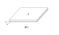
本教示の一実施形態は、ジェットスタック、プリントヘッド及び前記プリントヘッドを含むプリンタの形成を包含することができる。図1の斜視図では、圧電素子層10は接着材14によって転写キャリア12へ分離可能式に接着されている。圧電素子層10は、内部誘電体として機能するための例えばチタン酸ジルコン酸鉛層を、例えば約25μmから約150μmまでの間の厚さで含むことができる。圧電素子層10は、誘電PZTの各側面に導電層を設けるために、両側を例えば無電解メッキ処理を用いてニッケルでメッキされることが可能である。ニッケルメッキされたPZTは、本質的には、内部PZT材料に渡って電位差を発生させる平行板キャパシタとして機能する。キャリア12は、金属シート、プラスチックシートまたは別の転写キャリアを含むことが可能である。圧電素子層10を転写キャリア12へ付着する接着層14は、ダイシングテープ、熱プラスチックまたは別の接着材を含むことが可能である。別の実施形態では、転写キャリア12は、別の接着層14が不要であるように、粘着性熱プラスチック層等の物質であることが可能である。
One embodiment of the present teachings can include the formation of a jet stack, a printhead, and a printer that includes the printhead. In the perspective view of FIG. 1, the piezoelectric element layer 10 is detachably bonded to the
図1の構造体の形成後、図2に描かれているように、圧電素子層10はダイシングされ、複数の個々の圧電素子20が形成される。図2は4x3アレイの圧電素子を描いているが、より大きいアレイが形成される可能性もあることは認識されるであろう。例えば、現行のプリントヘッドは、344x20アレイの圧電素子20を有することも可能である。ダイシングは、ウェーハダイシングソー等のソーのような機械技術を用いて、ドライエッチングプロセスを用いて、レーザアブレーションプロセス、他を用いて実行されてもよい。隣接する各圧電素子20の完全な分離を確保するために、ダイシングプロセスは、接着材14の一部を除去して転写キャリア12上で停止した後に、または接着材14を通過してキャリア12内までダイシングした後に終了することができる。
After the structure of FIG. 1 is formed, the piezoelectric element layer 10 is diced as shown in FIG. 2 to form a plurality of individual
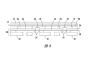
個々の圧電素子20を形成した後、図2のアッセンブリは、図3の断面図に描かれているように、ジェットスタックサブアッセンブリ30へ付着されることが可能である。図3の断面図は、図2の構造体のディテールをより良く示すために拡大されたものであり、2つの完全な圧電素子20及び1つの部分的な圧電素子20の断面を描いている。ジェットスタックサブアッセンブリ30は、既知の技術を用いて製造されることが可能である。ジェットスタックサブアッセンブリ30は、例えば、インレット/アウトレットプレート32と、ボディプレート34と、接着性ダイヤフラムの付着材38を用いてボディプレート34へ付着されるダイヤフラム36とを含むことが可能である。ダイヤフラム36は、後述するように、完成したデバイスにおいてインクを通すための複数の開口40を含むことが可能である。図3の構造体は、さらに、プロセスにおけるこの時点で周囲空気を充填されることが可能な複数のボイド42も含む。ダイヤフラムの付着材38は、ダイヤフラム36を介する開口40が覆われるように、単一のポリマシート等の材料の固体シートであってもよい。
After forming the individual
ある実施形態では、図2の構造体は、ダイヤフラム36と圧電素子20との間の接着材を用いてジェットスタックサブアッセンブリ30へ付着されることが可能である。例えば、測定された一定量の接着材(個々には描かれていない)が圧電素子20の上面上、ダイヤフラム36上または双方の上の何れかへ分配される、スクリーン印刷される、ローラで延ばされる、等々が可能である。ある実施形態では、ダイヤフラム上へ、各圧電素子20毎に一滴の接着材が置かれてもよい。接着材を付した後、ジェットスタックサブアッセンブリ30及び圧電素子20は互いに位置合わせされ、次いで圧電素子20が接着材でダイヤフラム36へ機械的に接続される。接着材は、その接着材が図3の構造体をもたらすことに適する技術によって硬化される。
In some embodiments, the structure of FIG. 2 can be attached to the
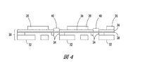
続いて、図3の構造体から転写キャリア12及び接着材14が除去され、図4の構造体がもたらされる。
Subsequently, the
次に、図4の構造体を覆って侵入型層が計量分配され、次には硬化されて侵入型層50が形成される。侵入型層は、例えば、コネチカット州ダンベリー所在のMiller−Stephenson Chemical社から市販されているEpon(商標)828エポキシ樹脂(重量で100パーツ)とオハイオ州コロンバス所在のHexion Specialty Chemicalsから市販されているEpikure(商標)3277硬化剤(重量で49パーツ)とを組み合わせたポリマであってもよい。未硬化の侵入型層は、図5に描かれているように、ダイヤフラム36の上面52の露出された部分を覆いかつ硬化に続いて圧電素子20を封入するに足る量で計量分配されることが可能である。侵入型層はさらに、図に描かれているように、ダイヤフラム36内の開口40も満たすことが可能である。ダイヤフラム36内の開口40を覆うダイヤフラムの付着材38は、未硬化の侵入型層が開口40を通過することを防止する。侵入型層50は、硬化の前または後の何れかで平坦化されることが可能である。平坦化は、例えば、材料のセルフレベリング性または機械的ワイピング及び加圧成形を含む技術によって実行されてもよい。
Next, the interstitial layer is dispensed over the structure of FIG. 4 and then cured to form the
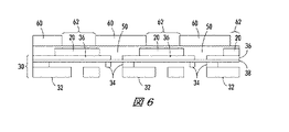
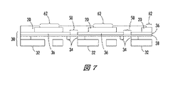
次に、侵入型層50は圧電素子20の上面から除去される。ある実施形態では、図6に描かれているように、既知のフォトリソグラフィ技術を用いて、パターン化されたフォトレジストマスク等のパターン化されたマスク60が開口62を伴って形成される。開口62は、侵入型層50の各圧電素子20を覆っている一部を露出させ、かつさらに、図に描かれているように、各圧電素子20の一部も露出させる。この実施形態では、露出された侵入型層50が湿式または乾式エッチングを用いて各圧電素子20の頂部から除去される。別の実施形態では、侵入型層50は各圧電素子20を露出させるためにレーザアブレーションを用いて除去されてもよく、パターン化されたマスク60の必要性が省かれる。
Next, the
侵入型層50が除去されて各圧電素子20の頂面が暴露された後、パターン化されたマスク60が使用されていれば、これが除去されて結果的に図7の構造体が形成される。次には、図8に描かれているように、図7の構造体を覆ってブランケット導電性トレース層80を形成することができる。トレース層80は、所望される最終設計の構造体に依存して、図示されているような共形層であってもよく、平坦な層であってもよい。トレース層80は、例えば化学気相堆積法、物理的気相成長法、金属メッキ及びスパッタリングである任意の充足したプロセスを用いて形成されてもよい。様々な実施形態において、トレース層80は、銅、アルミニウム、金、合金及びこれらの組合せから形成されてもよい。ある実施形態において、トレース層80は、約0.5マイクロメートル(μm)から約10μmまでの間、または約0.8μmから約1.1μmまでの間の平均厚さまで形成されることが可能であるが、製造されているデバイスの設計に依存して、他の厚さで足りる場合もある。ブランケットトレース層80は、誘電体侵入型層50と表面接触状態にあり、かつ導電性の各圧電素子20とも表面接触状態にある。
After the
ブランケット導電性トレース層80の形成後、トレース層80の表面を覆って、内部にトレース層80を露出させる開口を有するパターン化されたマスク82が形成される。パターン化されたマスク82は、従来のフォトリソグラフィ技術を用いて形成される、例えばフォトレジストであるパターン化された感光層であってもよい。パターン化されるマスク82の設計は、エッチングに続いてトレース層80により形成されるトレースルーティングの所望されるパターンに依存する。
After the blanket
続いて、導電層80の露出された部分を除去するために、湿式または乾式エッチングが実行される。侵入型層50は、エッチング停止層として用いられてもよい。エッチングの後は、パターン化されたマスク82が除去され、図9に描かれているものに類似する構造体がもたらされる。エッチングの後、各圧電素子20は、トレース層から形成される個々の導電トレース80へ電気接続される。各トレース80は、圧電素子20上に形成される。複数のトレース80と複数の圧電素子20との間の電気接触は、各トレース80と圧電素子20のうちの1つとの間の物理的接触(表面接触)を介して確立される。プリントヘッドの使用中、各トレース80は、各圧電素子が個々にアドレス可能であるように、各圧電素子20へ個々の電圧接続を供給する。
Subsequently, wet or dry etching is performed to remove the exposed portion of the
この実施形態は、フォトリソグラフィを用いる導電トレース層のパターニングについて記述しているが、パターン化されたトレース層を形成するためにリフトオフプロセスまたはレーザアブレーションプロセス等の他のパターニングプロセスも使用可能であることは理解されるであろう。 Although this embodiment describes patterning a conductive trace layer using photolithography, other patterning processes such as a lift-off process or a laser ablation process can also be used to form a patterned trace layer. Will be understood.
次には、図10に描かれているように、図9の構造体の表面を覆って誘電体不動態化層100を形成することができる。不動態化層100は導電トレース80を保護し、かつ追加処理用ベースとしての平面層を形成する。不動態化層100は、侵入型層50または別の誘電層を形成するポリマに類似する材料を含むことが可能である。追加処理は任意選択であって、パターン化の有無に関わらず追加の層102によって表される様々な導電及び/または誘電層を含むことが可能であり、かつ製造されているデバイスの設計に依存する。追加処理は、インクをルーティングしかつ/またはヒータ及びマニホールド機能のための積層を形成するために必要とされる層を包含することが可能である。
Next, as depicted in FIG. 10, a
次に、ダイヤフラム36を介する開口40は、インクがダイヤフラム36を介して通過できるように清浄化されることが可能である。開口40の清浄化は、接着性ダイヤフラムの付着材38、侵入型層50、不動態化層100及び追加層102(存在すれば)の一部を除去することを含む。さらに、電気的開放等の望ましくない電気特性をもたらさない限り、1つまたは複数のトレース80の一部が除去されてもよい。様々な実施形態では、化学的または機械的な除去技術が用いられてもよい。ある実施形態において、特にインレット/アウトレットプレート32、ボディプレート34及びダイヤフラム36が金属製である場合、セルフアライン式の除去プロセスは、図11に描かれているように、レーザビーム112を出力するレーザ110の使用を包含することが可能である。インレット/アウトレットプレート32、ボディプレート34及び設計に依存して、場合によりダイヤフラム36は、セルフアライン式のレーザアブレーションプロセスのためにレーザビーム112をマスキングすることができる。この実施形態では、CO2レーザ、エキシマレーザ、固体レーザ、銅蒸気レーザ及びファイバレーザ等のレーザを用いることができる。CO2レーザ及びエキシマレーザは、典型的には、エポキシを含むポリマをアブレートすることができる。CO2レーザは、低い動作コスト及び高い製造スループットを有することが可能である。図11には2つのレーザ110が描かれているが、単一のレーザビームが1つまたは複数のレーザパルスを用いて各ホールを順々に開いてもよい。別の実施形態では、単一の動作において2つ以上の開口が生成されることも可能である。例えば、その表面にマスクを当てることができ、次に単一の幅広レーザビームが、単一の幅広レーザビームからの1つまたは複数のパルスを用いて2つ以上の開口、または全ての開口を開放する可能性もある。インレット/アウトレットプレート32、ボディプレート34及び恐らくはダイヤフラム36によって形成されるマスクをオーバーフィルし得るCO2レーザビームは、順次各開口40を照射し、図11に描かれているように、接着性ダイヤフラムの付着材38、侵入型層50、不動態化層100及び追加層102を介して延長された開口を形成することも可能であり、最終的に図12の構造体が得られる。
Next, the
続いて、図13に描かれているように、インレット/アウトレットプレート32へ接着材(個々には描かれていない)で有孔プレート130を付着することができる。有孔プレート130は、印刷中にインクが通って放出されるノズル132を含む。有孔プレート132が付着されると、ジェットスタック134は完成する。
Subsequently, the
続いて、例えば接着材等の流体密封シール式接続部142を用いて、ジェットスタック134の上面へマニホールド140が接着されることが可能であって、結果的に図14に描かれているようなインクジェットプリントヘッド144が生じる。インクジェットプリントヘッド144は、マニホールド140の表面及びジェットスタック134の上面によって形成される、一定量のインクを貯蔵するためのインクリザーバ146を含むことが可能である。リザーバ146からのインクは、ジェットスタック134内のポート148を介して送出される。図14が簡易図であることは、理解されるであろう。実際のプリントヘッドは、図14には描かれていない、例えば左右への追加的構造体である様々な構造体及び差異を含んでもよいが、これらは、説明を単純にするために描画を省かれている。
図14は2つのポート148を描いているが、ある典型的なジェットスタックは、例えば344x20アレイのポートを有することが可能である。
Subsequently, the manifold 140 can be bonded to the upper surface of the
Although FIG. 14 depicts two
使用に際して、プリントヘッド144のマニホールド140内のリザーバ146は、一定量のインクを含む。プリントヘッドの最初のプライミングは、インクをリザーバ146からジェットスタック134内のポート148を介してジェットスタック134内のチャンバ150へと流れ込ませるために使用されることが可能である。各トレース80上へ印加される電圧152に反応して、各PZT圧電素子20は、デジタル信号に応答する適切な時間に偏向する。圧電素子20の偏向はダイヤフラム36を屈曲させ、これによりチャンバ150内に圧力パルスが生じ、インクの一滴がノズル132から放出される。
In use, the
これにより、上述の方法及び構造体は、インクジェットプリンタのためのジェットスタック134を形成する。ある実施形態では、ジェットスタック134は、図14に描かれているようなインクジェットプリントヘッド144の一部として使用されることが可能である。
Thereby, the method and structure described above forms a
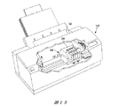
図15は、本教示の一実施形態による、1つまたは複数のプリントヘッド144及び1つまたは複数のノズル132から噴出されるインク164を含むプリンタ162を描いたものである。各プリントヘッド144は、用紙、プラスチック、他等の印刷媒体166上へ所望される画像を生成するために、デジタル命令に従って動作するように適合化される。各プリントヘッド144は、スワス毎に印刷画像を生成するために、走査動作において印刷媒体166に対して前後に移動してもよい。或いは、プリントヘッド144が固定して保持されかつ印刷媒体166がそれと相対的に移動されて、単一の通過でプリントヘッド144と同じ幅の画像が生成されてもよい。さらに、印刷は、プリントヘッド144を用いてドラム等の中間被加熱構造体(単純化のために個々には描かれていない)上にインクパターン164を形成することと、このドラムを用いて画像を印刷媒体166上へ転写(転写定着)することを含んでもよい。プリントヘッド144は、印刷媒体166より狭い、またはこれと同幅であることが可能である。
FIG. 15 depicts a
このように、上述の実施形態は、プリンタに使用されることが可能なインクジェットプリントヘッドのためのジェットスタックを提供することができる。ジェットスタックを形成するための本方法及びジェットスタック完成品は、電極または他の導電素子を圧電素子へ電気結合する導体の流れを包含するためのスタンドオフ層の使用を必要としない。さらに、本方法では、各圧電素子の頂部から侵入型層を除去する必要がない。この実施形態では、デジタル信号に応答して電圧152を各圧電素子20へ供給するために用いられるパターン化ブランケットトレース層80は、光フォトリソグラフィを用いてパターン化されることが可能である。その結果、フレックス回路電極を各圧電素子へ電気結合する液体またはペースト接着材を包含するためのスタンドオフ層を必要としないジェットスタック及びプリントヘッドが得られる。同様に、このジェットスタック及びプリントヘッドは、各圧電素子へ電圧をルーティングするためのフレックス回路も必要としない。圧電素子へ繋がるフレックス回路が不要であることから、圧電素子20及びトレース80へのアクセスは単純化され、任意の必要な作業のし直しが単純化される。
Thus, the above-described embodiments can provide a jet stack for an inkjet printhead that can be used in a printer. The present method for forming a jet stack and the finished jet stack do not require the use of a standoff layer to contain a conductor stream that electrically couples an electrode or other conductive element to a piezoelectric element. Furthermore, in this method, it is not necessary to remove the interstitial layer from the top of each piezoelectric element. In this embodiment, the patterned
圧電素子へ電圧を供給するためには、トレース80及び制御側プリントヘッド電子機器へ様々なルーティング及び配線を電気結合することができる。これらのルーティング及び配線は、必要に応じて複雑なルーティングを解くために追加の誘電層及び金属層によって形成されることが可能であり、かつPCBまたはフレックス回路によって供給されてもよい。さらに、入力/出力の再分配がより効率的であれば、スペーシングの制約も緩和される可能性がある。トレースは、ドライバチップまたは特定用途向け集積回路を、トレース80を介して圧電素子へ電気結合するために、例えばフリップチップボンディングを用いてジェットスタック134の頂面へ取り付けさせることが可能である。その他のフレックス回路接続は、クロック信号、データ信号及び制御信号のみならず様々な電圧供給に限定されることが可能であり、一方で圧電素子への直接的接続は省かれる。本教示は、先行する幾つかのプロセスよりも、コンポーネント、材料及び組立てステージの数を減らすことができる。さらに、本教示は、結果として導電路またはトレースの解像度を高めることができ、よって、レーザカットパーツをなくすることによるトランスデューサ密度の高度化及び清浄度の向上を見込んでいる。収量は、例えばチャネル間ショート及びチャネル−接地間ショートである短絡等の現行の多くの故障モードの解消によって向上する可能性がある。素材セットを単純化することにより、インクジェットプリントヘッドに典型的なインク及び他の環境素材に付随する適合性も改善されることが可能である。このタイプの配線技術は、さらに、画像入力スキャナ及び他のセンサまたはトランスデューサ等の他の高密度アレイ構造体へも適用されることが可能である。
In order to supply voltage to the piezoelectric element, various routing and wiring can be electrically coupled to the
この例示的な方法は、一連の行動またはイベントとして示されかつ記述されているが、本発明がこのような行動またはイベントの例示された順序に限定されないことは認識されるであろう。例えば、幾つかの行動は、本教示に従って、本明細書に例示されかつ/または記述されている順序とは異なる順序で、かつ/または他の行動またはイベントと同時に発生する場合もある。さらに、本教示による方法論を実装する際には、例示されている全てのステップが必要とされなくてもよい。明細書の本文及び図面を参照すれば、一般的な当業者には他の実施形態も明らかとなるであろう。 Although this exemplary method has been shown and described as a series of actions or events, it will be appreciated that the invention is not limited to the illustrated order of such actions or events. For example, some actions may occur in an order different from that illustrated and / or described herein and / or coincident with other actions or events in accordance with the present teachings. Moreover, not all illustrated steps may be required to implement a methodology in accordance with the present teachings. Other embodiments will be apparent to those of ordinary skill in the art by reference to the text and drawings of the specification.
Claims (7)
ダイヤフラム内の複数の開口をダイヤフラム付着材で覆うステップと、
前記ダイヤフラムへボディプレートを前記ダイヤフラム付着材で付着するステップと、
複数の圧電素子を前記ダイヤフラムへ付着するステップと、
隣接する圧電素子間に直接侵入型層を形成することであって、各圧電素子の表面は前記侵入型層を介して露出されるステップと、
前記侵入型層上へ複数のパターン化されたトレースを形成するステップであって、複数のトレースが、前記侵入型層に物理的に接触し、且つ、前記複数の圧電素子と物理的及び電気的に接触するように形成され、各トレースが、前記複数の圧電素子の1つに対して物理的な接触によって電気的に結合されるステップと、
前記複数のトレースを覆って誘電体不動態化層を形成するステップを含み、
前記ダイヤフラム付着材は、前記侵入型層が形成される際に、前記侵入型層が前記ダイヤフラム内の前記複数の開口を通過することを防止する、
ことを特徴とする方法。 A method for forming an inkjet printhead comprising:
Covering a plurality of openings in the diaphragm with a diaphragm adhering material;
Attaching a body plate to the diaphragm with the diaphragm adhering material;
A step of attaching a plurality of piezoelectric elements to the diaphragm,
A method comprising: forming a direct interstitial layer between the piezoelectric element, the surface of each piezoelectric element is exposed through the interstitial layer adjacent,
And forming a plurality of patterned traced to the interstitial layer, a plurality of traces, in physical contact with the interstitial layer, and the physical and electrical and the plurality of piezoelectric elements is formed so as to be in contact with each trace, the steps that are electrically coupled by physical contact with one of said plurality of piezoelectric elements,
Look including the step of forming the dielectric passivation layer over said plurality of traces,
The diaphragm adhering material prevents the interstitial layer from passing through the plurality of openings in the diaphragm when the interstitial layer is formed.
A method characterized by that .
前記ブランケットトレース層を覆って感光層をパターン化するステップと、
前記パターン化された感光層を前記複数のトレースを形成するためのパターンとして用いて、前記ブランケットトレース層をエッチングするステップをさらに含む、請求項1に記載の方法。 Forming a blanket trace layer to the plurality of piezoelectric elements and electrical contact to as the interstitial layer,
A step of patterning a photosensitive layer over the blanket trace layer,
Using the patterned photosensitive layer as a pattern for forming a plurality of traces, further comprising the step of the blanket trace layer etching method of claim 1.
前記複数のトレースを形成すべく前記ブランケットトレース層の一部をアブレートするために、レーザパターニングプロセスを実行するステップをさらに含む、請求項1に記載の方法。 Forming a blanket trace layer,
Wherein the plurality of portions of the blanket trace layer to form traces for ablating, further comprising the step of performing the laser patterning process, method according to claim 1.
ことを特徴とする請求項1に記載の方法。 Electrical contact between the plurality of traces and the plurality of piezoelectric elements is established by surface contact between the plurality of traces and the plurality of piezoelectric elements;
The method according to claim 1.
ことを特徴とする請求項2に記載の方法。 The interstitial layer is used as an etch stop layer when etching the blanket trace layer to form the plurality of traces,
The method according to claim 2.
Applications Claiming Priority (2)
| Application Number | Priority Date | Filing Date | Title |
|---|---|---|---|
| US13/053,968 | 2011-03-22 | ||
| US13/053,968 US8585183B2 (en) | 2011-03-22 | 2011-03-22 | High density multilayer interconnect for print head |
Publications (3)
| Publication Number | Publication Date |
|---|---|
| JP2012196960A JP2012196960A (en) | 2012-10-18 |
| JP2012196960A5 JP2012196960A5 (en) | 2015-04-09 |
| JP5793095B2 true JP5793095B2 (en) | 2015-10-14 |
Family
ID=46855316
Family Applications (1)
| Application Number | Title | Priority Date | Filing Date |
|---|---|---|---|
| JP2012042539A Expired - Fee Related JP5793095B2 (en) | 2011-03-22 | 2012-02-28 | Method for forming an inkjet printhead |
Country Status (4)
| Country | Link |
|---|---|
| US (1) | US8585183B2 (en) |
| JP (1) | JP5793095B2 (en) |
| KR (1) | KR101819882B1 (en) |
| CN (1) | CN102689517B (en) |
Families Citing this family (9)
| Publication number | Priority date | Publication date | Assignee | Title |
|---|---|---|---|---|
| US8727508B2 (en) * | 2011-11-10 | 2014-05-20 | Xerox Corporation | Bonded silicon structure for high density print head |
| US8826539B2 (en) * | 2012-05-16 | 2014-09-09 | Xerox Corporation | Method for flex circuit bonding without solder mask for high density electrical interconnect |
| US10607642B2 (en) * | 2013-03-18 | 2020-03-31 | Magnecomp Corporation | Multi-layer PZT microactuator with active PZT constraining layers for a DSA suspension |
| US9802408B2 (en) * | 2015-02-24 | 2017-10-31 | Xerox Corporation | Raised fluid pass-through structure in print heads |
| US9643408B1 (en) | 2016-02-09 | 2017-05-09 | Xerox Corporation | Joint quantization of drop probability functions in multi-size drop inkjet printers |
| US10166777B2 (en) | 2016-04-21 | 2019-01-01 | Xerox Corporation | Method of forming piezo driver electrodes |
| WO2018013093A1 (en) | 2016-07-12 | 2018-01-18 | Hewlett-Packard Development Company, L.P. | Printhead comprising a thin film passivation layer |
| CN111216452B (en) * | 2018-11-27 | 2021-08-17 | 西安增材制造国家研究院有限公司 | Piezoelectric type MEMS ink-jet printing head and manufacturing method |
| JP2021136248A (en) * | 2020-02-21 | 2021-09-13 | 株式会社ディスコ | Processing method for device wafer |
Family Cites Families (9)
| Publication number | Priority date | Publication date | Assignee | Title |
|---|---|---|---|---|
| US6464324B1 (en) * | 2000-01-31 | 2002-10-15 | Picojet, Inc. | Microfluid device and ultrasonic bonding process |
| JP2007290238A (en) * | 2006-04-25 | 2007-11-08 | Fuji Xerox Co Ltd | Manufacturing method for liquid droplet ejection head and liquid droplet ejection head |
| US7699441B2 (en) * | 2006-12-12 | 2010-04-20 | Eastman Kodak Company | Liquid drop ejector having improved liquid chamber |
| US7959266B2 (en) * | 2007-03-28 | 2011-06-14 | Xerox Corporation | Self aligned port hole opening process for ink jet print heads |
| US8082641B2 (en) * | 2007-06-01 | 2011-12-27 | Xerox Corporation | Method of manufacturing a ductile polymer-piezoelectric material composite |
| JP2009177149A (en) * | 2007-12-26 | 2009-08-06 | Konica Minolta Holdings Inc | Metal oxide semiconductor, method for manufacturing it, and thin-film transistor |
| US8857020B2 (en) * | 2008-05-23 | 2014-10-14 | Fujifilm Corporation | Actuators and methods of making the same |
| US8360557B2 (en) * | 2008-12-05 | 2013-01-29 | Xerox Corporation | Method for laser drilling fluid ports in multiple layers |
| JP5321832B2 (en) * | 2009-03-26 | 2013-10-23 | セイコーエプソン株式会社 | Liquid ejecting head, liquid ejecting apparatus, and actuator device |
-
2011
- 2011-03-22 US US13/053,968 patent/US8585183B2/en active Active
-
2012
- 2012-02-28 JP JP2012042539A patent/JP5793095B2/en not_active Expired - Fee Related
- 2012-03-21 KR KR1020120028622A patent/KR101819882B1/en active IP Right Grant
- 2012-03-21 CN CN201210090475.5A patent/CN102689517B/en not_active Expired - Fee Related
Also Published As
| Publication number | Publication date |
|---|---|
| US8585183B2 (en) | 2013-11-19 |
| KR20120107870A (en) | 2012-10-04 |
| KR101819882B1 (en) | 2018-01-19 |
| US20120242756A1 (en) | 2012-09-27 |
| CN102689517B (en) | 2015-07-22 |
| JP2012196960A (en) | 2012-10-18 |
| CN102689517A (en) | 2012-09-26 |
Similar Documents
| Publication | Publication Date | Title |
|---|---|---|
| JP5793095B2 (en) | Method for forming an inkjet printhead | |
| US8205971B2 (en) | Electrically grounded inkjet ejector and method for making an electrically grounded inkjet ejector | |
| US8585187B2 (en) | High density electrical interconnect for printing devices using flex circuits and dielectric underfill | |
| US8491747B2 (en) | Method for facilitating assembly of a printhead having a polymer layer | |
| JP4325693B2 (en) | Head module, liquid discharge head, and liquid discharge apparatus | |
| WO2001042017A1 (en) | Ink-jet head and printer | |
| JP5934058B2 (en) | In situ flexible circuit embossing to form electrical interconnects | |
| JP5914304B2 (en) | Inkjet print head | |
| JP5886723B2 (en) | Bonded silicon structures for high density printheads | |
| CN102689518B (en) | Use of photoresist material as an interstitial fill for pzt printhead fabrication | |
| WO2001042024A1 (en) | Ink jet head and printer | |
| JP3942118B2 (en) | Inkjet recording apparatus and inkjet head | |
| WO2001042023A1 (en) | Ink jet head, method of producing ink jet heads, and printer | |
| JP4586427B2 (en) | Inkjet recording head | |
| CN107303757B (en) | Method of forming piezoelectric actuator electrode | |
| JP2013067166A (en) | High density electrical interconnect using limited density flex circuits | |
| JP6604035B2 (en) | Liquid ejection device and method of manufacturing liquid ejection device | |
| JP2007001192A (en) | Manufacturing method for head module, manufacturing method for liquid delivering head, and manufacturing method for liquid delivering apparatus | |
| JP5800738B2 (en) | Inkjet print head | |
| JP3667134B2 (en) | Inkjet head | |
| US8205969B2 (en) | Jet stack with precision port holes for ink jet printer and associated method | |
| JP2006044217A (en) | Inkjet recording head and inkjet recorder | |
| JPH11170494A (en) | Ink jet recording device | |
| JPH11198365A (en) | Ink jet head | |
| JP2001063037A (en) | Ink jet head |
Legal Events
| Date | Code | Title | Description |
|---|---|---|---|
| RD04 | Notification of resignation of power of attorney |
Free format text: JAPANESE INTERMEDIATE CODE: A7424 Effective date: 20131011 |
|
| A521 | Request for written amendment filed |
Free format text: JAPANESE INTERMEDIATE CODE: A523 Effective date: 20150223 |
|
| A621 | Written request for application examination |
Free format text: JAPANESE INTERMEDIATE CODE: A621 Effective date: 20150223 |
|
| A871 | Explanation of circumstances concerning accelerated examination |
Free format text: JAPANESE INTERMEDIATE CODE: A871 Effective date: 20150223 |
|
| A975 | Report on accelerated examination |
Free format text: JAPANESE INTERMEDIATE CODE: A971005 Effective date: 20150304 |
|
| A131 | Notification of reasons for refusal |
Free format text: JAPANESE INTERMEDIATE CODE: A131 Effective date: 20150428 |
|
| A521 | Request for written amendment filed |
Free format text: JAPANESE INTERMEDIATE CODE: A523 Effective date: 20150624 |
|
| TRDD | Decision of grant or rejection written | ||
| A01 | Written decision to grant a patent or to grant a registration (utility model) |
Free format text: JAPANESE INTERMEDIATE CODE: A01 Effective date: 20150714 |
|
| A61 | First payment of annual fees (during grant procedure) |
Free format text: JAPANESE INTERMEDIATE CODE: A61 Effective date: 20150807 |
|
| R150 | Certificate of patent or registration of utility model |
Ref document number: 5793095 Country of ref document: JP Free format text: JAPANESE INTERMEDIATE CODE: R150 |
|
| R250 | Receipt of annual fees |
Free format text: JAPANESE INTERMEDIATE CODE: R250 |
|
| R250 | Receipt of annual fees |
Free format text: JAPANESE INTERMEDIATE CODE: R250 |
|
| R250 | Receipt of annual fees |
Free format text: JAPANESE INTERMEDIATE CODE: R250 |
|
| LAPS | Cancellation because of no payment of annual fees |
