JP5788409B2 - Minimally invasive heart valve - Google Patents
Minimally invasive heart valve Download PDFInfo
- Publication number
- JP5788409B2 JP5788409B2 JP2012546343A JP2012546343A JP5788409B2 JP 5788409 B2 JP5788409 B2 JP 5788409B2 JP 2012546343 A JP2012546343 A JP 2012546343A JP 2012546343 A JP2012546343 A JP 2012546343A JP 5788409 B2 JP5788409 B2 JP 5788409B2
- Authority
- JP
- Japan
- Prior art keywords
- valve
- stent
- minimally invasive
- heart valve
- tubular stent
- Prior art date
- Legal status (The legal status is an assumption and is not a legal conclusion. Google has not performed a legal analysis and makes no representation as to the accuracy of the status listed.)
- Active
Links
- ALNXFULNBUSUBH-UHFFFAOYSA-N CC(C)[NH+](S)[I-]C Chemical compound CC(C)[NH+](S)[I-]C ALNXFULNBUSUBH-UHFFFAOYSA-N 0.000 description 1
Images


Classifications
-
- A—HUMAN NECESSITIES
- A61—MEDICAL OR VETERINARY SCIENCE; HYGIENE
- A61F—FILTERS IMPLANTABLE INTO BLOOD VESSELS; PROSTHESES; DEVICES PROVIDING PATENCY TO, OR PREVENTING COLLAPSING OF, TUBULAR STRUCTURES OF THE BODY, e.g. STENTS; ORTHOPAEDIC, NURSING OR CONTRACEPTIVE DEVICES; FOMENTATION; TREATMENT OR PROTECTION OF EYES OR EARS; BANDAGES, DRESSINGS OR ABSORBENT PADS; FIRST-AID KITS
- A61F2/00—Filters implantable into blood vessels; Prostheses, i.e. artificial substitutes or replacements for parts of the body; Appliances for connecting them with the body; Devices providing patency to, or preventing collapsing of, tubular structures of the body, e.g. stents
- A61F2/02—Prostheses implantable into the body
- A61F2/24—Heart valves ; Vascular valves, e.g. venous valves; Heart implants, e.g. passive devices for improving the function of the native valve or the heart muscle; Transmyocardial revascularisation [TMR] devices; Valves implantable in the body
- A61F2/2412—Heart valves ; Vascular valves, e.g. venous valves; Heart implants, e.g. passive devices for improving the function of the native valve or the heart muscle; Transmyocardial revascularisation [TMR] devices; Valves implantable in the body with soft flexible valve members, e.g. tissue valves shaped like natural valves
- A61F2/2415—Manufacturing methods
-
- A—HUMAN NECESSITIES
- A61—MEDICAL OR VETERINARY SCIENCE; HYGIENE
- A61F—FILTERS IMPLANTABLE INTO BLOOD VESSELS; PROSTHESES; DEVICES PROVIDING PATENCY TO, OR PREVENTING COLLAPSING OF, TUBULAR STRUCTURES OF THE BODY, e.g. STENTS; ORTHOPAEDIC, NURSING OR CONTRACEPTIVE DEVICES; FOMENTATION; TREATMENT OR PROTECTION OF EYES OR EARS; BANDAGES, DRESSINGS OR ABSORBENT PADS; FIRST-AID KITS
- A61F2/00—Filters implantable into blood vessels; Prostheses, i.e. artificial substitutes or replacements for parts of the body; Appliances for connecting them with the body; Devices providing patency to, or preventing collapsing of, tubular structures of the body, e.g. stents
- A61F2/02—Prostheses implantable into the body
- A61F2/24—Heart valves ; Vascular valves, e.g. venous valves; Heart implants, e.g. passive devices for improving the function of the native valve or the heart muscle; Transmyocardial revascularisation [TMR] devices; Valves implantable in the body
- A61F2/2412—Heart valves ; Vascular valves, e.g. venous valves; Heart implants, e.g. passive devices for improving the function of the native valve or the heart muscle; Transmyocardial revascularisation [TMR] devices; Valves implantable in the body with soft flexible valve members, e.g. tissue valves shaped like natural valves
- A61F2/2418—Scaffolds therefor, e.g. support stents
-
- A—HUMAN NECESSITIES
- A61—MEDICAL OR VETERINARY SCIENCE; HYGIENE
- A61F—FILTERS IMPLANTABLE INTO BLOOD VESSELS; PROSTHESES; DEVICES PROVIDING PATENCY TO, OR PREVENTING COLLAPSING OF, TUBULAR STRUCTURES OF THE BODY, e.g. STENTS; ORTHOPAEDIC, NURSING OR CONTRACEPTIVE DEVICES; FOMENTATION; TREATMENT OR PROTECTION OF EYES OR EARS; BANDAGES, DRESSINGS OR ABSORBENT PADS; FIRST-AID KITS
- A61F2/00—Filters implantable into blood vessels; Prostheses, i.e. artificial substitutes or replacements for parts of the body; Appliances for connecting them with the body; Devices providing patency to, or preventing collapsing of, tubular structures of the body, e.g. stents
- A61F2/02—Prostheses implantable into the body
- A61F2/30—Joints
- A61F2002/30001—Additional features of subject-matter classified in A61F2/28, A61F2/30 and subgroups thereof
- A61F2002/30108—Shapes
- A61F2002/30199—Three-dimensional shapes
- A61F2002/30205—Three-dimensional shapes conical
- A61F2002/3021—Three-dimensional shapes conical frustoconical
-
- A—HUMAN NECESSITIES
- A61—MEDICAL OR VETERINARY SCIENCE; HYGIENE
- A61F—FILTERS IMPLANTABLE INTO BLOOD VESSELS; PROSTHESES; DEVICES PROVIDING PATENCY TO, OR PREVENTING COLLAPSING OF, TUBULAR STRUCTURES OF THE BODY, e.g. STENTS; ORTHOPAEDIC, NURSING OR CONTRACEPTIVE DEVICES; FOMENTATION; TREATMENT OR PROTECTION OF EYES OR EARS; BANDAGES, DRESSINGS OR ABSORBENT PADS; FIRST-AID KITS
- A61F2/00—Filters implantable into blood vessels; Prostheses, i.e. artificial substitutes or replacements for parts of the body; Appliances for connecting them with the body; Devices providing patency to, or preventing collapsing of, tubular structures of the body, e.g. stents
- A61F2/95—Instruments specially adapted for placement or removal of stents or stent-grafts
- A61F2002/9528—Instruments specially adapted for placement or removal of stents or stent-grafts for retrieval of stents
-
- A—HUMAN NECESSITIES
- A61—MEDICAL OR VETERINARY SCIENCE; HYGIENE
- A61F—FILTERS IMPLANTABLE INTO BLOOD VESSELS; PROSTHESES; DEVICES PROVIDING PATENCY TO, OR PREVENTING COLLAPSING OF, TUBULAR STRUCTURES OF THE BODY, e.g. STENTS; ORTHOPAEDIC, NURSING OR CONTRACEPTIVE DEVICES; FOMENTATION; TREATMENT OR PROTECTION OF EYES OR EARS; BANDAGES, DRESSINGS OR ABSORBENT PADS; FIRST-AID KITS
- A61F2/00—Filters implantable into blood vessels; Prostheses, i.e. artificial substitutes or replacements for parts of the body; Appliances for connecting them with the body; Devices providing patency to, or preventing collapsing of, tubular structures of the body, e.g. stents
- A61F2/95—Instruments specially adapted for placement or removal of stents or stent-grafts
- A61F2002/9534—Instruments specially adapted for placement or removal of stents or stent-grafts for repositioning of stents
-
- A—HUMAN NECESSITIES
- A61—MEDICAL OR VETERINARY SCIENCE; HYGIENE
- A61F—FILTERS IMPLANTABLE INTO BLOOD VESSELS; PROSTHESES; DEVICES PROVIDING PATENCY TO, OR PREVENTING COLLAPSING OF, TUBULAR STRUCTURES OF THE BODY, e.g. STENTS; ORTHOPAEDIC, NURSING OR CONTRACEPTIVE DEVICES; FOMENTATION; TREATMENT OR PROTECTION OF EYES OR EARS; BANDAGES, DRESSINGS OR ABSORBENT PADS; FIRST-AID KITS
- A61F2220/00—Fixations or connections for prostheses classified in groups A61F2/00 - A61F2/26 or A61F2/82 or A61F9/00 or A61F11/00 or subgroups thereof
- A61F2220/0025—Connections or couplings between prosthetic parts, e.g. between modular parts; Connecting elements
- A61F2220/0075—Connections or couplings between prosthetic parts, e.g. between modular parts; Connecting elements sutured, ligatured or stitched, retained or tied with a rope, string, thread, wire or cable
-
- A—HUMAN NECESSITIES
- A61—MEDICAL OR VETERINARY SCIENCE; HYGIENE
- A61F—FILTERS IMPLANTABLE INTO BLOOD VESSELS; PROSTHESES; DEVICES PROVIDING PATENCY TO, OR PREVENTING COLLAPSING OF, TUBULAR STRUCTURES OF THE BODY, e.g. STENTS; ORTHOPAEDIC, NURSING OR CONTRACEPTIVE DEVICES; FOMENTATION; TREATMENT OR PROTECTION OF EYES OR EARS; BANDAGES, DRESSINGS OR ABSORBENT PADS; FIRST-AID KITS
- A61F2230/00—Geometry of prostheses classified in groups A61F2/00 - A61F2/26 or A61F2/82 or A61F9/00 or A61F11/00 or subgroups thereof
- A61F2230/0002—Two-dimensional shapes, e.g. cross-sections
- A61F2230/0017—Angular shapes
- A61F2230/0021—Angular shapes square
-
- A—HUMAN NECESSITIES
- A61—MEDICAL OR VETERINARY SCIENCE; HYGIENE
- A61F—FILTERS IMPLANTABLE INTO BLOOD VESSELS; PROSTHESES; DEVICES PROVIDING PATENCY TO, OR PREVENTING COLLAPSING OF, TUBULAR STRUCTURES OF THE BODY, e.g. STENTS; ORTHOPAEDIC, NURSING OR CONTRACEPTIVE DEVICES; FOMENTATION; TREATMENT OR PROTECTION OF EYES OR EARS; BANDAGES, DRESSINGS OR ABSORBENT PADS; FIRST-AID KITS
- A61F2230/00—Geometry of prostheses classified in groups A61F2/00 - A61F2/26 or A61F2/82 or A61F9/00 or A61F11/00 or subgroups thereof
- A61F2230/0002—Two-dimensional shapes, e.g. cross-sections
- A61F2230/0017—Angular shapes
- A61F2230/0023—Angular shapes triangular
-
- A—HUMAN NECESSITIES
- A61—MEDICAL OR VETERINARY SCIENCE; HYGIENE
- A61F—FILTERS IMPLANTABLE INTO BLOOD VESSELS; PROSTHESES; DEVICES PROVIDING PATENCY TO, OR PREVENTING COLLAPSING OF, TUBULAR STRUCTURES OF THE BODY, e.g. STENTS; ORTHOPAEDIC, NURSING OR CONTRACEPTIVE DEVICES; FOMENTATION; TREATMENT OR PROTECTION OF EYES OR EARS; BANDAGES, DRESSINGS OR ABSORBENT PADS; FIRST-AID KITS
- A61F2230/00—Geometry of prostheses classified in groups A61F2/00 - A61F2/26 or A61F2/82 or A61F9/00 or A61F11/00 or subgroups thereof
- A61F2230/0002—Two-dimensional shapes, e.g. cross-sections
- A61F2230/0028—Shapes in the form of latin or greek characters
- A61F2230/0054—V-shaped
-
- A—HUMAN NECESSITIES
- A61—MEDICAL OR VETERINARY SCIENCE; HYGIENE
- A61F—FILTERS IMPLANTABLE INTO BLOOD VESSELS; PROSTHESES; DEVICES PROVIDING PATENCY TO, OR PREVENTING COLLAPSING OF, TUBULAR STRUCTURES OF THE BODY, e.g. STENTS; ORTHOPAEDIC, NURSING OR CONTRACEPTIVE DEVICES; FOMENTATION; TREATMENT OR PROTECTION OF EYES OR EARS; BANDAGES, DRESSINGS OR ABSORBENT PADS; FIRST-AID KITS
- A61F2230/00—Geometry of prostheses classified in groups A61F2/00 - A61F2/26 or A61F2/82 or A61F9/00 or A61F11/00 or subgroups thereof
- A61F2230/0063—Three-dimensional shapes
- A61F2230/0067—Three-dimensional shapes conical
-
- A—HUMAN NECESSITIES
- A61—MEDICAL OR VETERINARY SCIENCE; HYGIENE
- A61F—FILTERS IMPLANTABLE INTO BLOOD VESSELS; PROSTHESES; DEVICES PROVIDING PATENCY TO, OR PREVENTING COLLAPSING OF, TUBULAR STRUCTURES OF THE BODY, e.g. STENTS; ORTHOPAEDIC, NURSING OR CONTRACEPTIVE DEVICES; FOMENTATION; TREATMENT OR PROTECTION OF EYES OR EARS; BANDAGES, DRESSINGS OR ABSORBENT PADS; FIRST-AID KITS
- A61F2230/00—Geometry of prostheses classified in groups A61F2/00 - A61F2/26 or A61F2/82 or A61F9/00 or A61F11/00 or subgroups thereof
- A61F2230/0063—Three-dimensional shapes
- A61F2230/0073—Quadric-shaped
- A61F2230/008—Quadric-shaped paraboloidal
-
- A—HUMAN NECESSITIES
- A61—MEDICAL OR VETERINARY SCIENCE; HYGIENE
- A61F—FILTERS IMPLANTABLE INTO BLOOD VESSELS; PROSTHESES; DEVICES PROVIDING PATENCY TO, OR PREVENTING COLLAPSING OF, TUBULAR STRUCTURES OF THE BODY, e.g. STENTS; ORTHOPAEDIC, NURSING OR CONTRACEPTIVE DEVICES; FOMENTATION; TREATMENT OR PROTECTION OF EYES OR EARS; BANDAGES, DRESSINGS OR ABSORBENT PADS; FIRST-AID KITS
- A61F2250/00—Special features of prostheses classified in groups A61F2/00 - A61F2/26 or A61F2/82 or A61F9/00 or A61F11/00 or subgroups thereof
- A61F2250/0014—Special features of prostheses classified in groups A61F2/00 - A61F2/26 or A61F2/82 or A61F9/00 or A61F11/00 or subgroups thereof having different values of a given property or geometrical feature, e.g. mechanical property or material property, at different locations within the same prosthesis
- A61F2250/0039—Special features of prostheses classified in groups A61F2/00 - A61F2/26 or A61F2/82 or A61F9/00 or A61F11/00 or subgroups thereof having different values of a given property or geometrical feature, e.g. mechanical property or material property, at different locations within the same prosthesis differing in diameter
Description
本発明は医療機器技術分野に関し、特に低侵襲性心臓弁に関する。 The present invention relates to the field of medical device technology, and more particularly to a minimally invasive heart valve.
心臓弁は薄くて強靭なシート状組織からなり、弁は心臓の収縮と拡張に伴って開放、閉鎖する。正常な人の心臓は毎日約10万回拍動し、弁は10万回開放、閉鎖する。故に心臓の弁は柔軟性、強靭性、弾力性を生涯保たなければならず心臓の圧力と血液の流れを長期的に受けなければならない。 The heart valve consists of a thin and strong sheet-like tissue, and the valve opens and closes as the heart contracts and dilates. A normal person's heart beats about 100,000 times daily and the valve opens and closes 100,000 times. Therefore, the heart valve must maintain its flexibility, toughness and elasticity throughout its life, and must be subjected to heart pressure and blood flow for a long time.
心臓弁膜症はわが国で最もよく見られる心臓疾患の一つであり、その中で主なものはリウマチ熱による弁膜損傷である。近年、人口の高齢化が進むにつれ、弁膜の退行性病変(石灰化や粘液変性などを含む)及び代謝障害性弁膜損傷はわが国でも日増しに増加している。この他、先天性弁膜症もよく見られる先天性心臓疾患の一つである。 Valvular disease is one of the most common heart diseases in Japan, and the main one is rheumatic fever valve damage. In recent years, with the aging of the population, degenerative lesions (including calcification and mucus degeneration) and metabolic disorders of valvular membranes are increasing day by day in Japan. In addition, congenital valvular disease is one of the most common congenital heart diseases.
前世紀60年代、Albert STAR教授が最初の人工心臓機械弁を人体に移植し、Alain CARPENTIER教授が最初の人工心臓生体弁を人体に移植して以来、瞬く間に50年余りが過ぎた。二種類の弁は二つの智慧であり、両方の共通点は共に心臓弁膜症患者に生命の新たなターニングポイントを与えてくれたことである。 In the 60s of the last century, more than 50 years have passed since Professor Albert STAR transplanted the first artificial heart mechanical valve into the human body and Professor Alain CARPENTIER transplanted the first artificial heart biological valve into the human body. The two types of valves are two wisdoms, and the common point of both is that they provide a new turning point in life for patients with valvular heart disease.
メリットもあればデメリットもある。長年の臨床運用に基づき、次のような対比が見られる。機械弁が患者の体内に移植された後、患者は抗凝固薬を生涯服用する必要がある。抗凝固薬は出血や血栓塞栓症を非常に起こしやすくなるなど、複数の副作用がある。これに対して、生体弁は抗凝固薬を服用する必要はないが、生体弁が患者の体内に移植された後、弁葉は早期中期石灰化を起こすため、弁の狭窄や閉鎖不全を起こす。石灰化現象は中高年患者において最も重い。 There are advantages and disadvantages. Based on many years of clinical practice, the following contrasts can be seen. After the mechanical valve is implanted in the patient's body, the patient needs to take anticoagulant drugs for life. Anticoagulants have a number of side effects, such as bleeding and thromboembolism. In contrast, biological valves do not need to take anticoagulants, but after the biological valve is implanted into the patient's body, the valve leaflets cause early mid-stage calcification, resulting in stenosis or insufficiency of the valve . Calcification is the most severe in middle-aged and elderly patients.
正に上記の理由により、科学者は、この二種類の弁が誕生してからの半世紀において、それらをどのように改善し、進歩させるかをずっと探求してきた。早期の研究方向は主に石灰化を防ぐことにあり、後期は医療技術の発展に伴い、研究分野が弁構造の改善に拡大された。 For exactly the above reasons, scientists have continually explored how to improve and improve them in the half-century since the birth of these two valves. The early research direction was mainly to prevent calcification, and in the latter period, with the development of medical technology, the research field was expanded to improve the valve structure.
重度な弁閉鎖不全の患者、外科弁置換手術が適されない高齢の患者、末期腫瘍かつ弁閉鎖不全の患者、複数臓器機能不全かつ弁膜症の患者など、かなり多くの危険性が高い心臓弁膜症の患者に対して、新たな創が小さい低侵襲治療が必要となる。心臓弁の低侵襲治療は外科の心臓弁置換手術の触発のもとで発展したものであり、ここ数年来、経皮的低侵襲心臓弁膜症手術、例えば経皮的肺動脈弁ステント置換術、経皮的大動脈弁置換術、経皮的僧帽弁修復術及び経皮的僧帽弁輪縫縮術が時運に応じて現れた。2000年後、次々と人間に応用されて成功し、初歩的結果によりこれらの方法は実行可能であることが示されが、低侵襲治療の有効性と危険性についてさらに評価し比較する必要があり、現在のところ、外科手術に耐えられない危険性の高い患者のみに応用されている。低侵襲性経皮的肺動脈弁移植術、経皮的大動脈弁置換術、経皮的僧帽弁修復術、経皮的僧帽弁輪形成術及び経皮的僧帽弁輪縫縮術はみな実行可能であり、移植後の心臓機能が改善されている。 For patients with severe valve regurgitation, elderly patients who are not suitable for surgical valve replacement, end-stage tumors and patients with valve regurgitation, multi-organ dysfunction and valvular disease A minimally invasive treatment with a small new wound is required for the patient. Minimally invasive therapies of heart valves have been developed under the instigation of surgical heart valve replacement surgery, and for the past few years, percutaneous minimally invasive cardiac valvular surgery, such as percutaneous pulmonary valve replacement, Percutaneous aortic valve replacement, percutaneous mitral valve repair, and percutaneous mitral annuloplasty emerged over time. After 2000, it has been successfully applied to humans one after another, and rudimentary results show that these methods are feasible, but the effectiveness and risk of minimally invasive treatment needs to be further evaluated and compared At present, it is applied only to high-risk patients who cannot withstand surgery. Minimally invasive percutaneous pulmonary valve implantation, percutaneous aortic valve replacement, percutaneous mitral valve repair, percutaneous mitral annuloplasty and percutaneous mitral annuloplasty It is feasible and has improved cardiac function after transplantation.
ここ10年で低侵襲治療の方向は、以下の通りである。内科でも外科でも治療できる病例について、低侵襲はどちらも治療でき、外科手術では治療できない病例についても低侵襲であれば治療できる。新世紀における弁膜症の低侵襲治療の研究は明らかに加速し、低侵襲治療による経皮的心臓弁移植術は実験研究から小規模な臨床と並行した研究段階にまで発展した。弁膜症の低侵襲治療は技術上のボトルネックを突破し、広い臨床応用が迅速に実現される可能性があるため、再び低侵襲心臓病分野の注目の的になっている。 The direction of minimally invasive treatment in the last 10 years is as follows. For cases that can be treated by both internal medicine and surgery, both minimally invasive can be treated, and cases that cannot be treated by surgery can be treated if minimally invasive. Research into minimally invasive treatment of valvular disease in the new century has clearly accelerated, and percutaneous heart valve transplantation with minimally invasive treatment has evolved from experimental research to a research stage parallel to small clinical practice. Minimally invasive treatment of valvular disease is once again attracting attention in the field of minimally invasive heart disease, as it breaks through the technical bottleneck and widespread clinical application may be realized quickly.
特許文献1はバルーン拡張型の低侵襲性心臓弁を記載しており、可塑変形のステントに生体弁を固定し、径方向にステントを圧縮することでそれをバルーンに固定し、経皮的移植し、大動脈弁に達した後、バルーンを加圧してステントを拡張し固定する。このようなバルーン拡張型の生体弁には以下のような欠点と問題が存在する。ステント圧縮とバルーン拡張の過程で生体弁の弁葉組織構造が大きな損傷を受け、心臓弁移植後の使用寿命に重大な影響を与えることである。心臓弁のステントはバルーンの直径で決まり、サイズが小さすぎると、弁は弛んだり、動いたりするリスクがあり、2回のバルーンの拡張を行うしかない。サイズが大きすぎると、大動脈弁口が裂けるリスクがあり、他の合併症を発症する。このような心臓弁はバルーンが一旦拡張されると再載置することができないため、載置する位置が適切でない場合、その場で患者に危篤の危険が及ぶ。心臓弁が一旦移植されると、問題が起きても、回収することはできず、外科手術で置換するしかない。
特許文献2は自己拡張型の低侵襲性心臓弁を記載しており、自己拡張するステントに生体弁を固定し、ステントをキャリヤーのカテーテルに入れ、経皮的移植し、大動脈弁に達した後、ステントを置き、ステント自身の構造により大動脈弁口に固定する。このような自己拡張型の生体弁には以下のような欠点と問題が存在する。ステントの長さが長すぎ、開口設計が理想的ではなく、左右冠動脈口の血行動力学に影響しやすく、心臓機能が異常をきたす。心臓弁の載置位置が適切でないと、再載置することができないため、患者に危篤の危険が及ぶ。心臓弁が一旦移植されると、問題が起きても、回収することはできず、外科手術で置換するしかない。
特許文献3は低侵襲性人工心臓弁を記載しており、拡張と圧縮が可能な管状ステントに弁葉を縫合し、これとセット設計された移植及び回収装置を使用し、経皮的移植と低侵襲性取り出しを行い、弁の置換を行う。このような心臓弁には以下のような欠点と問題が存在する。ステントは糸織成構造であるため、圧縮と拡張の過程で、網目が容易に変形し、径方向の支持力が不安定になる。ステント外側には複数のバーブが設けられ、変位防止の作用を果たすが、血管壁への損傷が大きく、また内皮化後、ステント回収は血管を容易に裂き、予期した回収目的を実現し難くする。ステントの設計は左右冠動脈口の位置が考慮されるが、2〜3個の開口しか残していないため、左右冠動脈血流への影響を無くすことができず、また、心臓弁を置換するときに位置決めが難しい。
現在、臨床に用いられる全ての製品は構造分野での探求が難しい情況にある。現在の生体心臓弁は一旦開くと再載置できず、載置する位置が適切でない場合、その場で患者に危篤の危険が及ぶ。 Currently, all products used in clinical practice are difficult to explore in the structural field. Once the current biological heart valve is opened, it cannot be re-placed, and if the placement position is not appropriate, there is a risk of serious injury to the patient on the spot.
[発明の開示]
これらの問題に鑑み、本発明は血流衝撃による心臓弁の変位を防止し、心臓弁が一旦開くと再載置できない問題を解決する低侵襲性心臓弁を提供する。
[Disclosure of the Invention]
In view of these problems, the present invention provides a minimally invasive heart valve that prevents displacement of the heart valve due to blood flow shock and solves the problem that the heart valve cannot be re-mounted once it is opened.
上記の目的を実現するために、本発明は以下の技術手段を提供する。 In order to achieve the above object, the present invention provides the following technical means.
管状ステントと弁とを備えた低侵襲性心臓弁であって、前記管状ステントの一端は円錐台構造であり、他端は開口状であり、かつ、前記開口状の他端の直径は前記円錐台の一端の直径よりも大きく、前記弁は前記管状ステントの円錐台構造の一端に貼り付けられ、前記管状ステントの開口状の他端の頂部に心臓弁の送達回収孔が設けられ、前記管状ステントの円錐台端は、その母線が直線、円弧、又は直線と円弧の結合である低侵襲性心臓弁。 A minimally invasive heart valve comprising a tubular stent and a valve, wherein one end of the tubular stent has a truncated cone structure, the other end has an opening shape, and the diameter of the other end of the opening shape is the cone. Larger than the diameter of one end of the platform, the valve is affixed to one end of the frustoconical structure of the tubular stent, the delivery recovery hole of the heart valve is provided at the top of the other open end of the tubular stent, and the tubular The frustoconical end of the stent is a minimally invasive heart valve whose generatrix is a straight line, an arc, or a combination of a straight line and an arc.
好ましくは、前記管状ステントの開口端はラッパ状であり、かつ、前記管状ステントの全体は両端が大きく、中間が小さい構造である前記低侵襲性心臓弁。 Preferably, the open end of the tubular stent has a trumpet shape, and the tubular stent has a structure in which both ends are large and the middle is small.
好ましくは、前記管状ステントは複数の菱形ステントユニットからなる網目構造である前記低侵襲性心臓弁。 Preferably, the tubular stent is a minimally invasive heart valve having a mesh structure composed of a plurality of rhombus stent units.
好ましくは、前記管状ステントは両端を除き、内部の網目が閉鎖型構造である前記低侵襲性心臓弁。 Preferably, the tubular stent is the minimally invasive heart valve except for both ends, and the inner mesh is a closed structure.
好ましくは、前記管状ステントは開口状の一端から円錐台状の他端にかけて、網目が徐々に小さくなる前記低侵襲性心臓弁。 Preferably, the tubular stent is the minimally invasive heart valve in which the mesh gradually decreases from one open end to the other end of the truncated cone.
好ましくは、前記開口箇所の網目は左右冠動脈の直径よりも大きい前記低侵襲性心臓弁。 Preferably, the network of the opening portion is the minimally invasive heart valve larger than the diameter of the left and right coronary arteries.
好ましくは、前記管状ステントの網目はステントロッドからなり、かつ、網目が大きいほど前記ステントロッドは太くなる前記低侵襲性心臓弁。 Preferably, the network of the tubular stent includes a stent rod, and the larger the mesh, the thicker the stent rod, the less invasive heart valve.
好ましくは、前記管状ステントの開口端は三つの菱形網目からなり、花びら状に四方へ開き、かつ、前記心臓弁の送達回収孔は三つであり、それぞれ前記三つの菱形網目の頂端に設けられている前記低侵襲性心臓弁。 Preferably, the open end of the tubular stent is composed of three rhombus meshes, opens in four directions like petals, and the delivery collection holes of the heart valve are three, each provided at the top end of the three rhombus meshes. Said minimally invasive heart valve.
好ましくは、前記管状ステントはニッケルチタン合金材料である前記低侵襲性心臓弁。 Preferably, said minimally invasive heart valve wherein said tubular stent is a nickel titanium alloy material.
好ましくは、前記弁は縫合線により前記管状ステント内に縫製固定されている前記低侵襲性心臓弁。 Preferably, the minimally invasive heart valve is secured to the tubular stent by a suture line.
好ましくは、前記弁は具体的に弁葉と弁裾であり、前記弁葉と弁裾は一体式構造、又は弁葉を前記弁裾に縫製した分割式構造に設計される前記低侵襲性心臓弁。 Preferably, the valve is specifically a leaflet and a valve skirt, and the valve leaf and the valve skirt are integrally structured, or the minimally invasive heart designed in a split structure in which a valve leaf is sewn to the valve skirt. valve.
好ましくは、前記弁葉は生体組織、高分子材料、金属材料、又は組織工学弁とする前記低侵襲性心臓弁。 Preferably, the valve leaf is a living tissue, a polymer material, a metal material, or a tissue engineering valve.
好ましくは、前記弁葉と弁裾は分割式構造を採用し、前記弁裾は前記管状ステントの網目に縫製され、前記弁葉は前記弁裾に縫製される、又は弁裾とステント網目の両方に縫製される前記低侵襲性心臓弁。 Preferably, the valve leaf and the valve skirt adopt a split structure, the valve skirt is sewn to the mesh of the tubular stent, and the valve leaf is sewn to the valve hem, or both the valve hem and the stent mesh Said minimally invasive heart valve sewn in.
好ましくは、前記弁裾は生体組織、高分子材料、金属材料、又は組織工学弁とすることができる前記低侵襲性心臓弁。 Preferably, the valve base is the minimally invasive heart valve, which can be a biological tissue, a polymer material, a metal material, or a tissue engineering valve.
好ましくは、前記弁裾は同じ台形の三つの弁裾基体が縫製されてなる円錐台形状である前記低侵襲性心臓弁。 Preferably, the valve skirt has a truncated cone shape formed by sewing three valve-base bodies having the same trapezoid shape.
好ましくは、前記弁葉の基部はアーチ構造であり、前記弁葉の基部の両端に弁葉縫合耳状部が設けられ、前記弁葉縫合耳状部は前記管状ステントに縫製され、かつ、任意の隣接する二つの弁葉縫合耳状部は弁と弁の縫合線により一緒に縫合され、前記弁葉と弁裾は弁葉の基部のアーチ線に沿って縫合される前記低侵襲性心臓弁。 Preferably, the base portion of the leaflet has an arch structure, and a leaflet suture ear-like portion is provided at both ends of the base portion of the leaflet, and the leaflet suture ear-like portion is sewn to the tubular stent, and is optional. The minimally invasive heart valve in which two adjacent leaflet suture ears are stitched together by a valve and valve suture line, and the leaflet and valve hem are stitched along the arch line of the base of the leaflet .
好ましくは、前記弁は弁裾と弁葉の一体式構造を採用し、前記弁は管状ステントの網目に縫製され、かつ、前記弁の中部に縫合線により一本の横向きアーチ線を有している前記低侵襲性心臓弁。 Preferably, the valve adopts an integral structure of a valve skirt and a leaflet, the valve is sewn in a mesh of a tubular stent, and has a lateral arch line by a suture line in the inside of the valve. Said minimally invasive heart valve.
好ましくは、前記弁は生体組織、高分子材料、金属材料、又は組織工学弁とすることができる前記低侵襲性心臓弁。 Preferably, the valve is a minimally invasive heart valve, which can be a biological tissue, a polymer material, a metal material, or a tissue engineering valve.
好ましくは、前記弁は同じ形状の三つの弁基体からなり、前記弁基体の一端は、両側に弁葉縫合耳状部を設け、前記弁葉縫合耳状部は前記管状ステントに縫合され、任意の隣接する二つの弁葉縫合耳状部の根元が一緒に縫合され、前記弁基体に縫製された横向きアーチ線はステント網目と縫合される前記低侵襲性心臓弁。 Preferably, the valve is composed of three valve bases having the same shape, and one end of the valve base is provided with leaflet suture ears on both sides, and the leaflet suture ears are sewn to the tubular stent. The minimally invasive heart valve in which the roots of two adjacent leaflet suture ears are stitched together, and the transverse arch line sewn to the valve base is stitched to the stent network.
上記技術手段からわかるように、本発明の実施例では管状ステントの一端を開口状とし、かつ、開口状の一端の直径を円錐台状の他端の直径よりも大きくしているため、大動脈弁口の位置に有効的に固定でき、血流衝撃による心臓弁の変位を防止できる。弁は前記管状ステントの円錐台構造の他端に貼り付けられるため、左右冠動脈口を完全に避けることができ、冠動脈の血行動力学への影響がない。管状ステントの開口状の一端の頂部には心臓弁の送達回収孔が設けられており、心臓弁を置く過程で、載置する位置が適切でないことがわかった場合、ハンドルにより随時回収でき、再載置できる。 As can be seen from the above technical means, in the embodiment of the present invention, one end of the tubular stent has an opening shape, and the diameter of one end of the opening shape is larger than the diameter of the other end of the truncated cone shape. It can be effectively fixed at the position of the mouth, and the displacement of the heart valve due to blood flow impact can be prevented. Since the valve is affixed to the other end of the truncated cone structure of the tubular stent, the left and right coronary artery openings can be completely avoided, and there is no influence on the hemodynamics of the coronary artery. A delivery recovery hole for the heart valve is provided at the top of the open end of the tubular stent. If it is found that the placement position is not appropriate during the placement of the heart valve, it can be retrieved at any time by the handle. Can be placed.
また、本発明のステントの意匠は人体解剖学構造に適合し、大動脈弁口位置に有効的に固定でき、血流衝撃による心臓弁の変位を防止できる。 In addition, the stent design of the present invention is compatible with the human anatomy, can be effectively fixed at the position of the aortic valve opening, and can prevent displacement of the heart valve due to blood flow impact.
異なるステントロッド幅の設計と異なるステントユニット(網目)構造により、心臓弁の移植後、均一的な径方向の支持力を与え、血流衝撃による心臓弁の変位を防止できる。 Different stent rod width designs and different stent unit (mesh) structures provide uniform radial support after implantation of the heart valve and prevent heart valve displacement due to blood flow impact.
異なるステントロッド幅の設計と異なるステントユニット構造により、ステントの円周形状を適宜変形させることができ、大動脈弁口部分に有効的に貼り付けることができる。 With different stent rod width designs and different stent unit structures, the circumferential shape of the stent can be appropriately deformed and can be effectively affixed to the aortic valve orifice.
独自の弁縫合設計により、心臓弁の移植後、血管周囲の血液の滲み出しリスクを有効的に防止することができる。 The unique valve suturing design can effectively prevent the risk of seepage of blood around the blood vessel after implantation of the heart valve.
独自の弁葉結合部位及び結合点の縫合設計により、弁の動作過程でステントに対する付勢力の影響を有効的に低減させ、ステントの耐久性を強化することができる。 Due to the unique leaflet joint site and joint stitch design, the impact of the biasing force on the stent can be effectively reduced during the operation of the valve, and the durability of the stent can be enhanced.
独自の生体弁葉の形状設計により、弁の動作過程における耐久性を向上させることができる。 Durability in the operation process of the valve can be improved by the unique shape design of the living leaflets.
本発明とセットのキャリヤーのサイズは小さく(18F)、血管に対する刺激と損傷を有効的に低減させることができ、キャリヤーの先端はハンドルにより曲がり、大動脈弓の生理構造に適合し、大動脈弓部に対する損傷を避けることができる。 The size of the carrier of the present invention and the set is small (18F), which can effectively reduce irritation and damage to the blood vessel, the tip of the carrier is bent by the handle, adapts to the physiology of the aortic arch, and against the aortic arch Damage can be avoided.
本発明の実施例又は従来技術における技術手段をより明確に説明するために、実施例又は従来技術の説明に必要な図面について以下に簡単に説明する。以下の説明の中の図面は本発明の一部の実施例でしかなく、当該発明の属する技術の分野における通常の知識を有する者にとって、創造的労働をしない前提において、これらの図面に基づいて他の図面を得ることができることは言うまでもない。 In order to more clearly describe the technical means in the embodiments of the present invention or the prior art, the drawings necessary for describing the embodiments or the prior art will be briefly described below. The drawings in the following description are only some embodiments of the present invention, and based on these drawings on the premise that the person having ordinary knowledge in the technical field to which the invention belongs does not perform creative labor. It goes without saying that other drawings can be obtained.
実施形態
本発明は血流衝撃による心臓弁の変位を防止し、心臓弁が一旦開くと再載置できない問題を解決する低侵襲性心臓弁を開示する。
Embodiment
The present invention discloses a minimally invasive heart valve that prevents the heart valve from being displaced by a blood flow shock and solves the problem that the heart valve cannot be remounted once it is opened.
以下に本発明の実施例における図面をあわせて、本発明の実施例の技術手段について明瞭に全面的に説明する。説明する実施例は本発明の全部の実施例ではなく一部の実施例にすぎない。本発明の実施例に基づき、当該発明の属する技術の分野における通常の知識を有する者が創造的労働をしない前提で得られる他の実施例もすべて本発明の保護範囲に入ることは言うまでもない。 The technical means of the embodiments of the present invention will be clearly and entirely described below with reference to the drawings in the embodiments of the present invention. The described embodiments are only a part rather than all embodiments of the present invention. Needless to say, based on the embodiments of the present invention, all other embodiments obtained on the premise that a person having ordinary knowledge in the technical field to which the invention belongs does not perform creative labor fall within the protection scope of the present invention.
実施例1
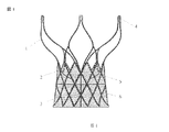
図1〜5を参照し、図1は本発明の実施例1の心臓弁の正面図であり、図2は本発明の実施例1の弁閉鎖状態時の心臓弁の平面図であり、図3は本発明の実施例1の弁開放状態時の心臓弁の平面図であり、図4は本発明の実施例1のステントの一部分の拡大図であり、図5は本発明の実施例1の心臓弁の圧縮状態の概略図である。
Example 1
1 to 5, FIG. 1 is a front view of the heart valve according to the first embodiment of the present invention, and FIG. 2 is a plan view of the heart valve in the valve closed state according to the first embodiment of the present invention. 3 is a plan view of the heart valve when the valve is opened according to the first embodiment of the present invention, FIG. 4 is an enlarged view of a part of the stent according to the first embodiment of the present invention, and FIG. 5 is a first embodiment of the present invention. It is the schematic of the compression state of this heart valve.
そのうち、1は管状ステント、2は弁葉、3は弁裾、4は心臓弁の送達回収孔、5は弁葉の縁形状、6は弁裾とステントの縫合痕、7は弁葉閉鎖線、8は弁葉とステントの縫合箇所、9は第1のステントユニット、10は第2のステントユニット、11は第3のステントユニットを示す。 Among them, 1 is a tubular stent, 2 is a leaflet, 3 is a valve hem, 4 is a heart valve delivery collection hole, 5 is a leaflet edge shape, 6 is a valve foot and a suture mark of a stent, 7 is a leaflet closing line , 8 are stitched portions of leaflets and stents, 9 is a first stent unit, 10 is a second stent unit, and 11 is a third stent unit.
本発明の低侵襲性心臓弁は、
管状ステント1と、弁葉2と、弁裾3とを備え、
前記管状ステント1の一端は円錐台構造であり、他端は開口状であり、かつ、前記開口状の他端の直径は前記円錐台構造の一端の直径よりも大きく、前記管状ステントの円錐台端は、その母線が直線、円弧、又は直線と円弧の結合である。
The minimally invasive heart valve of the present invention comprises
A
One end of the
弁2は弁裾3に縫製され、弁の縁形状5はアーチ状であり、弁裾3は前記管状ステント1の円錐台構造の一端に縫製して貼り付けられ、符号6は弁裾とステントの縫合痕である。
The
前記管状ステント1の開口状の他端の頂部に心臓弁の送達回収孔4が設けられる。
A
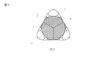
弁2は閉鎖状態時に閉鎖円形を呈し、三つの弁葉閉鎖線7により全周が等分されている。弁2が開放状態時に管状を呈する。
The
以上のように、本発明の実施例は管状ステントの他端を開口状とし、かつ、開口状の他端の直径を円錐台構造の一端の直径よりも大きくしているため、大動脈弁口の位置に有効的に固定でき、血流衝撃による心臓弁の変位を防止できる。弁は前記管状ステントの円錐台構造の一端に貼り付けられるため、左右冠動脈口を完全に避けることができ、冠動脈の血行動力学への影響がない。管状ステントの開口状の他端の頂部には心臓弁の送達回収孔が設けられており、心臓弁を置く過程で、載置する位置が適切でないことがわかった場合、ハンドルにより随時回収でき、再載置できる。 As described above, in the embodiment of the present invention, the other end of the tubular stent has an opening shape, and the diameter of the other end of the opening shape is larger than the diameter of one end of the truncated cone structure. The position can be effectively fixed, and the heart valve can be prevented from being displaced by a blood flow shock. Since the valve is affixed to one end of the truncated cone structure of the tubular stent, the left and right coronary artery openings can be completely avoided, and there is no influence on the hemodynamics of the coronary artery. A delivery recovery hole for a heart valve is provided at the top of the other open end of the tubular stent, and in the process of placing the heart valve, if it is found that the placement position is not appropriate, it can be collected at any time by the handle, Can be remounted.
前記管状ステント1の開口端はラッパ状又は花びら形状であり、独自のステント開口設計及び送達システムとの接続方式により、心臓弁を完全に置いた後、載置する位置が適切でなかったり又は弁の動きが正常ではないことがわかった場合、ハンドルにより完全に回収でき、心臓弁を再載置したり又は新しい心臓弁に交換することができる。
The open end of the
前記管状ステント1は複数の菱形又はその他の対称図形からなる網目構造であり、各網目をそれぞれ一つのステントユニットと呼ぶ。本発明の管状ステント1は複数のステントユニットからなる。管状ステント1は開口状の一端から円錐台構造の他端にかけて、網目が徐々に小さくなり、開口状の一端に近いほどステントユニットは大きくなり、ラッパ状開口端のステントユニットが最も大きい。図4に、第1のステントユニット9、第2のステントユニット10、第3のステントユニット11が示されているが、そのうち、第1のステントユニット9は管状ステント1の底部のステントユニットであり、第3のステントユニット11はラッパ開口端の頂部のステントユニットであり、第2のステントユニット10は管状ステント1の中間位置のステントユニットである。図面から、第3のステントユニット11の網目が最も大きく、第1のステントユニット9の網目が最も小さく、また、第2のステントユニット10の網目のサイズは第1のステントユニット9と第3のステントユニット11の間であることがわかる。
The
本実施例では3種類のステントユニットしか挙げていないが、その他のステントユニットについては逓増する網目構造を採用してもよいし、同じ網目構造を採用してもよく、開口端の網目構造が最も大きく、直管端の網目構造が最も小さいことを確保できればよく、本発明は上記3種類のステントユニットに限るものではないと当業者は理解できる。 In this embodiment, only three types of stent units are listed. However, for other stent units, an increasing network structure or the same network structure may be employed, and the network structure at the open end is the most. A person skilled in the art can understand that the present invention is not limited to the above-described three types of stent units as long as it is possible to ensure that the network structure is large and has the smallest network structure at the straight pipe end.
開口端の網目、即ち第3のステントユニット11の網目は左右冠動脈の直径より大きいため、左右冠動脈を避けることができる。管状ステントの網目はステントロッドからなり、即ち各ステントユニットはいずれもステントロッドからなる閉鎖ユニットであり、かつ、網目が大きくなれば前記ステントロッドは太くなる。異なるステントロッド幅の設計と異なるステントユニット構造により、心臓弁の移植後、均一的な径方向の支持力を与え、血流衝撃による心臓弁の変位を防止できる。また、ステントの円周形状も適宜変形させることができ、大動脈弁口部分に有効的に貼り付けることができる。管状ステント構造設計は一層ずつ収縮するため、上から下まで管状ステントの金属密度は異なり、ラッパ開口箇所までに三つの点しかない。均一な支持力を提供するために、設計時に上に向かうほどステントのロッドも太くする。網目が大きいほどステントも太くなり、ステントのロッドが細くなるほど容易に変形するとも理解でき、このように、心臓弁の下部は容易に変形するため、大動脈弁口部分に有効的に貼り付けることができ、上部は容易に変形しないため、血流衝撃による心臓弁の変位を防止できる。
Since the mesh at the open end, that is, the mesh of the
管状ステント1の開口端は三つの菱形のステントユニットからなり、花びら状に外へ開き、かつ、前記心臓弁の送達回収孔4は三つであり、それぞれ前記三つの菱形網目の頂端に設けられている。管状ステント1はニッケルチタン合金管をレーザー彫刻してなり、熱処理、ジェーピング、サンドブラスト、研磨等の工程を経て設計した構造に製作する。
The open end of the
図6〜11を参照し、図6は本発明の実施例1の弁葉設計構造の概略図であり、図7は本発明の実施例1の弁裾構造の概略図であり、図8は本発明の実施例1の弁葉の折り畳み図であり、図9は本発明の実施例1の弁葉と弁裾の縫合展開図であり、図10は本発明の実施例1の弁裾縫合立体図であり、図11は本発明の実施例1の弁葉と、弁裾と、ステントの縫合痕概略図である。 6 to 11, FIG. 6 is a schematic diagram of the leaflet design structure of the first embodiment of the present invention, FIG. 7 is a schematic diagram of the valve foot structure of the first embodiment of the present invention, and FIG. FIG. 9 is a folded view of a leaflet of Example 1 of the present invention, FIG. 9 is a suture development view of a leaflet and a valve foot of Example 1 of the present invention, and FIG. 10 is a valve foot suture of Example 1 of the present invention. FIG. 11 is a schematic view of a leaflet, a valve skirt, and a suture mark of a stent according to Example 1 of the present invention.
そのうち、2は弁葉、3は弁裾、12は弁葉縫合耳状部、13は弁葉と弁裾の縫合線、14は弁裾と弁裾の縫合線、15は弁と弁の縫合線を示す。 Of these, 2 is a leaflet, 3 is a valve hem, 12 is a valve leaf stitching ear, 13 is a suture line between the valve leaf and the valve skirt, 14 is a suture line between the valve hem and the valve skirt, and 15 is a suture between the valve and the valve. Show the line.
前記弁2の基部はアーチ構造であり、前記弁の基部の両端(即ちアーチ形状のアーチ線と直線と接する両端)に弁葉縫合耳状部12が設けられ、前記弁葉縫合耳状部12は前記管状ステント1に縫製され、かつ、任意の隣接する二つの弁葉縫合耳状部12は弁の基部と接する位置(即弁と弁の縫合線15の位置)により一緒に縫合され、前記弁2の底部のアーチ線は前記弁裾3に縫合される。
The base of the
前記弁2は、牛心膜、ブタ心膜、ブタ弁、馬心膜、牛頚静脈などの生体組織を選んでもよいし、PU、e−PTFEなどの高分子材料を選んでもよいし、特殊加工で製作されたニッケルチタン合金片などの金属材料を選んでもよいし、組織工学弁を選んでもよい。
The
弁裾3は同じ台形の三つの弁裾基体が縫製されてなる円錐台形状である。任意の二つの弁裾基体の隣接する縁が一緒に縫合され、符号14は弁裾と弁裾の縫合線である。
The
弁裾3は、牛心膜、ブタ心膜、ブタ弁、馬心膜、牛頚静脈などの生体組織を選んでもよいし、PU、e−PTFEなどの高分子材料を選んでもよいし、特殊加工で製作されたニッケルチタン合金片などの金属材料を選んでもよいし、組織工学弁を選んでもよい。
The
本発明の低侵襲性心臓弁は複数の規格を有し、直径はそれぞれ20〜29mm、流入口の直径は23〜31mm、流出口の直径は35〜50mm、心臓弁の高さは35〜50mmである。 The minimally invasive heart valve of the present invention has a plurality of standards, each having a diameter of 20 to 29 mm, an inlet diameter of 23 to 31 mm, an outlet diameter of 35 to 50 mm, and a heart valve height of 35 to 50 mm. It is.
図12を参照し、図12は本発明の実施例1の心臓弁移植後の冠動脈口との位置関係の概略図である。 Referring to FIG. 12, FIG. 12 is a schematic view of the positional relationship with the coronary artery opening after heart valve transplantation in Example 1 of the present invention.
そのうち、1は管状ステント、16は左冠動脈、17は右冠動脈、18は大動脈弁口を示す。 Of these, 1 is a tubular stent, 16 is a left coronary artery, 17 is a right coronary artery, and 18 is an aortic valve opening.
心臓弁は大動脈弁口18の位置に置かれる。本発明の心臓弁頭部、即ちラッパ開口箇所には弁が設けられておらず、かつ、網目(即ちステントユニット)は大きく、網目は左右冠動脈16、17よりも遥かに大きいため、左右冠動脈16、17を完全に避けることができる。
The heart valve is positioned at the
実施例2
図13〜20を参照し、図13は本発明の実施例2の心臓弁の正面図であり、図14は本発明の実施例2の心臓弁の圧縮状態の概略図であり、図15は本発明の実施例2の弁設計構造の概略図であり、図16は本発明の実施例2の弁の折り畳み図であり、図17は本発明の実施例2の弁縫合展開図であり、図18は本発明の実施例2の弁縫合立体図であり、図19は本発明の実施例2の弁とステントの縫合痕概略図であり、図20は本発明の実施例2の心臓弁移植後の冠動脈口との位置関係の概略図である。
Example 2
13 to 20, FIG. 13 is a front view of the heart valve according to the second embodiment of the present invention, FIG. 14 is a schematic view of a compressed state of the heart valve according to the second embodiment of the present invention, and FIG. FIG. 16 is a schematic view of the valve design structure of Example 2 of the present invention, FIG. 16 is a folded view of the valve of Example 2 of the present invention, and FIG. 17 is a valve suture development view of Example 2 of the present invention; FIG. 18 is a three-dimensional view of valve suturing according to the second embodiment of the present invention, FIG. 19 is a schematic view of the suture mark of the valve and stent according to the second embodiment of the present invention, and FIG. 20 is a heart valve according to the second embodiment of the present invention. It is the schematic of the positional relationship with the coronary artery opening after a transplant.
そのうち、1は管状ステント、2は弁、3は心臓弁の送達回収孔、4は弁とステントの縫合箇所、5はステントと弁の縫合痕、6は弁葉縫合耳状部、7は弁と弁の縫合線、8は左冠動脈、9は右冠動脈、10は大動脈弁口を示す。 Among them, 1 is a tubular stent, 2 is a valve, 3 is a heart valve delivery / recovery hole, 4 is a suture point of the valve and stent, 5 is a suture mark of the stent and valve, 6 is a leaflet suture ear, 7 is a valve And the suture line of the valve, 8 is the left coronary artery, 9 is the right coronary artery, and 10 is the aortic valve opening.
管状ステント1の構造は実施例1と同じであり、同じく開口端に心臓弁の送達回収孔3が設けられる。ここで同じ説明を省略する。
The structure of the
弁2は同じ不規則形状な三つの弁基体が縫製されてなり、全体形状は弁葉と弁裾を縫製してなる弁形状と同じであり、前記弁2は弁葉と弁裾を一体式構造に設計している。
The
前記弁基体の一端は、両側に弁葉縫合耳状部6を設け、前記弁葉縫合耳状部6は前記管状ステント1に縫合され、前記弁2の弁基体のうち、前記弁の中部に縫合線により一本の横向きアーチ線を縫製されており、横向きの弁の縫合線と前記管状ステント1は縫合して固定され、ステントと弁の縫合痕5がこの横向きアーチ線である。任意の隣接する二つの弁葉縫合耳状部6が一緒に縫合され、弁と弁の縫合線7がこの縫合位置である。
One end of the valve base is provided with leaf-leaf stitching ears 6 on both sides, and the leaf-leaf stitching ears 6 are stitched to the
本発明は以下の方法により大動脈弁の位置に置くことができる。
実施方法1
外科手術により胸開置換。病変の大動脈弁を拡張した後、心臓弁を大動脈弁の位置に置く。
The present invention can be placed at the position of the aortic valve by the following method.
Surgical replacement of the thoracotomy. After dilation of the lesioned aortic valve, the heart valve is placed at the aortic valve position.
実施方法2
心臓弁をキャリヤーに入れ、胸に小さな切口を開け、内径がキャリヤーよりも大きなシース管を心尖部から挿入し、DSA装置の誘導のもと、バルーンを大動脈弁に置き、バルーンを加圧した後、病変の弁を拡張し、バルーンを抜去した後、シース管により心臓弁を搭載したキャリヤーを入れ、DSAの誘導で大動脈弁位置に到達した後、心臓弁を置くとともに、キャリヤーを体外へ抜去し、切口を縫合する。
Place the heart valve in the carrier, open a small incision in the chest, insert a sheath tube with a larger inner diameter than the carrier through the apex, place the balloon on the aortic valve under the guidance of the DSA device, and pressurize the balloon After expanding the valve of the lesion and removing the balloon, the carrier carrying the heart valve is inserted by the sheath tube, and after reaching the aortic valve position by the induction of DSA, the heart valve is placed and the carrier is removed from the body. Suture the cut.
実施方法3
股動脈箇所に小さな切口を開け、シース管を入れ、DSA装置の誘導のもと、バルーンを大動脈弁に置き、バルーンを加圧した後、病変の弁を拡張し、バルーンを抜去した後、シース管により心臓弁を搭載したキャリヤーを入れ、DSAの誘導で大動脈弁位置に到達した後、心臓弁を置く。置く過程において、載置する位置が適切でないことがわかった場合、キャリヤーにより心臓弁を回収できる。弁が完全に開いた後であってキャリヤーが離れる前に、先に心臓弁の載置する位置が適切であるか否か、弁の動きが正常か否かを検査し、心臓弁のサイズ選択が適切でない、又は弁の動きが理想的でないとわかった場合、キャリヤーにより完全に回収でき、体外に抜去し、新しい心臓弁に交換できる。
Open a small incision in the hip artery, insert a sheath tube, place the balloon on the aortic valve under the guidance of the DSA device, pressurize the balloon, expand the valve of the lesion, remove the balloon, and then sheath A carrier carrying a heart valve is inserted through a tube, and after reaching the aortic valve position by induction of DSA, the heart valve is placed. In the process of placing, if it is found that the placement position is not appropriate, the heart valve can be retrieved by the carrier. After the valve is fully opened and before the carrier leaves, it is checked whether the heart valve is in the proper position and whether the valve is operating normally. Is not appropriate or if the valve movement is not ideal, it can be completely recovered by the carrier, removed from the body, and replaced with a new heart valve.
以上のように、本発明は管状ステントの一端を開口状とし、かつ、開口状の一端の直径を円錐台構造の他端の直径よりも大きくしているため、大動脈弁口の位置に有効的に固定でき、血流衝撃による心臓弁の変位を防止できる。弁は前記管状ステントの円錐台構造の他端に貼り付けられるため、左右冠動脈口を完全に避けることができ、冠動脈の血行動力学への影響がない。管状ステントの開口状の一端の頂部には心臓弁の送達回収孔が設けられており、心臓弁を置く過程で、載置する位置が適切でないことがわかった場合、ハンドルにより随時回収でき、再載置できる。本発明は弁葉と弁裾の一体化設計を採用してもよいし、両者が分離している分割式設計を採用してもよく、縫合により設置できる。 As described above, the present invention is effective at the position of the aortic valve opening because one end of the tubular stent has an opening shape and the diameter of one end of the opening shape is larger than the diameter of the other end of the truncated cone structure. The heart valve can be prevented from being displaced by a blood flow shock. Since the valve is affixed to the other end of the truncated cone structure of the tubular stent, the left and right coronary artery openings can be completely avoided, and there is no influence on the hemodynamics of the coronary artery. A delivery recovery hole for the heart valve is provided at the top of the open end of the tubular stent. Can be placed. The present invention may adopt an integrated design of the leaflet and the valve skirt, or may adopt a split design in which both are separated, and can be installed by stitching.
また、本発明のステントの意匠は人体解剖学構造に適合し、大動脈弁口位置に有効的に固定でき、血流衝撃による心臓弁の変位を防止できる。 In addition, the stent design of the present invention is compatible with the human anatomy, can be effectively fixed at the position of the aortic valve opening, and can prevent displacement of the heart valve due to blood flow impact.
異なるステントロッド幅の設計と異なるステントユニット(網目)構造により、心臓弁の移植後、均一的な径方向の支持力を与え、血流衝撃による心臓弁の変位を防止できる。 Different stent rod width designs and different stent unit (mesh) structures provide uniform radial support after implantation of the heart valve and prevent heart valve displacement due to blood flow impact.
異なるステントロッド幅の設計と異なるステントユニット構造により、ステントの円周形状を適宜変形させることができ、大動脈弁口箇部分に有効的に貼り付けることができる。 With different stent rod width designs and different stent unit structures, the circumferential shape of the stent can be appropriately deformed and can be effectively affixed to the aortic valve portion.
独自の弁縫合設計により、心臓弁の移植後、血管周囲の血液の滲み出しリスクを有効的に防止することができる。 The unique valve suturing design can effectively prevent the risk of seepage of blood around the blood vessel after implantation of the heart valve.
独自の弁葉結合部位及び結合点の縫合設計により、弁の動作過程でステントに対する付勢力の影響を有効的に低減させ、ステントの耐久性を向上させることができる。 The suture design of the unique leaflet joint site and joint point can effectively reduce the influence of the biasing force on the stent during the operation of the valve and improve the durability of the stent.
独自の生体弁葉形状設計により、弁の動作過程における耐久性を向上させることができる。 The unique design of the living leaflet shape can improve the durability of the valve in the operation process.
本発明とセットのキャリヤーのサイズは小さく(18F)、血管に対する刺激と損傷を有効的に低減させることができ、キャリヤーの先端はハンドルにより曲がり、大動脈弓の生理構造に適合し、大動脈弓部に対する損傷を避けることができる。 The size of the carrier of the present invention and the set is small (18F), which can effectively reduce irritation and damage to the blood vessel, the tip of the carrier is bent by the handle, adapts to the physiology of the aortic arch, and against the aortic arch Damage can be avoided.
本発明の各実施例は漸進的に説明したが、各実施例において重点的に説明しているのは他の実施例と異なる部分であるため、各実施例の間で同一類似部分については互いに参照できる。 Although each embodiment of the present invention has been described progressively, what is mainly described in each embodiment is a portion different from the other embodiments. You can refer to it.
開示された実施例の上記説明について、当該発明の属する技術の分野における通常の知識を有する者は実施又は本発明を利用できる。これら実施例の複数の変更について、当業者にとって容易に想到でき、本文で定義する一般的原理は本発明の思想又は範囲を超えない限り、その他の実施例において実施できる。よって、本発明は本文に示されるこれら実施例に限定されるものではなく、本文で開示した原理及び新規的特徴と一致する最も広い範囲に符合するものである。
以下に、出願当初の特許請求の範囲の記載事項をそのまま付記しておく。
[1]
管状ステントと弁とを備えた低侵襲性心臓弁であって、
前記管状ステントの一端は円錐台構造であり、他端は開口状であり、かつ、前記開口状の他端の直径は前記円錐台構造の一端の直径よりも大きく、
前記弁は前記管状ステントの円錐台構造の一端に貼り付けられ、
前記管状ステントの開口状の他端の頂部に心臓弁の送達回収孔が設けられ、
前記管状ステントの円錐台端は、母線が直線、円弧、又は直線と円弧の結合であることを特徴とする低侵襲性心臓弁。
[2]
前記管状ステントの開口端はラッパ状であり、かつ、前記管状ステントの全体は両端が大きく、中間が小さい構造であることを特徴とする請求項1に記載の低侵襲性心臓弁。
[3]
前記管状ステントは複数の菱形ステントユニットからなる網目構造であることを特徴とする請求項2に記載の低侵襲性心臓弁。
[4]
前記管状ステントは、両端を除き、内部の網目が閉鎖型構造であることを特徴とする請求項2に記載の低侵襲性心臓弁。
[5]
前記管状ステントは、開口状の他端から円錐台構造の一端にかけて、網目が徐々に小さくなることを特徴とする請求項3に記載の低侵襲性心臓弁。
[6]
前記開口箇所の網目は左右冠動脈の直径よりも大きいことを特徴とする請求項5に記載の低侵襲性心臓弁。
[7]
前記管状ステントの網目はステントロッドからなり、かつ、網目が大きいほど前記ステントロッドは太くなることを特徴とする請求項6に記載の低侵襲性心臓弁。
[8]
前記管状ステントの開口端は三つの菱形網目からなり、花びら状に四方へ開き、かつ、前記心臓弁の送達回収孔は三つであり、それぞれ前記三つの菱形網目の頂端に設けられていることを特徴とする請求項7に記載の低侵襲性心臓弁。
[9]
前記管状ステントはニッケルチタン合金材料であることを特徴とする請求項1に記載の低侵襲性心臓弁。
[10]
前記弁は縫合線により前記管状ステント内に縫製して固定されていることを特徴とする請求項1に記載の低侵襲性心臓弁。
[11]
前記弁は具体的に弁葉と弁裾であり、前記弁葉と弁裾は一体式構造、又は弁葉を前記弁裾に縫製した分割式構造に設計されることを特徴とする請求項9に記載の低侵襲性心臓弁。
[12]
前記弁葉は生体組織、高分子材料、金属材料、又は組織工学弁とすることができることを特徴とする請求項11に記載の低侵襲性心臓弁。
[13]
前記弁葉と弁裾は分割式構造を採用し、前記弁裾は前記管状ステントの網目に縫製され、前記弁葉は前記弁裾に縫製される、又は弁裾とステント網目の両方に縫製されることを特徴とする請求項11に記載の低侵襲性心臓弁。
[14]
前記弁裾は生体組織、高分子材料、金属材料、又は組織工学弁とすることができることを特徴とする請求項13に記載の低侵襲性心臓弁。
[15]
前記弁裾は同じ台形形状の三つの弁裾基体が縫製されてなる円錐台形状であることを特徴とする請求項11に記載の低侵襲性心臓弁。
[16]
前記弁葉の基部はアーチ構造であり、前記弁葉の基部の両端に弁葉縫合耳状部が設けられ、前記弁葉縫合耳状部は前記管状ステントに縫製され、かつ、任意の隣接する二つの弁葉縫合耳状部は弁と弁の縫合線により一緒に縫合され、前記弁葉と弁裾は弁葉の基部のアーチ線に沿って縫合されることを特徴とする請求項13〜15のいずれか1項に記載の低侵襲性心臓弁。
[17]
前記弁は弁裾と弁葉の一体式構造を採用し、前記弁は管状ステントの網目に縫製され、かつ、前記弁の中部に縫合線により一本の横向きアーチ線を縫製されていることを特徴とする請求項11に記載の低侵襲性心臓弁。
[18]
前記弁は生体組織、高分子材料、金属材料、又は組織工学弁とすることができることを特徴とする請求項17に記載の低侵襲性心臓弁。
[19]
前記弁は同じ形状の三つの弁基体からなり、前記弁基体の一端は両側に弁葉縫合耳状部を設け、前記弁葉縫合耳状部は前記管状ステントに縫合され、任意の隣接する二つの弁葉縫合耳状部の根元が一緒に縫合され、前記弁基体に縫製された横向きアーチ線はステント網目と縫合されることを特徴とする請求項17に記載の低侵襲性心臓弁。
With respect to the above description of the disclosed embodiments, those having ordinary knowledge in the technical field to which the invention pertains may practice or utilize the invention. Multiple modifications of these embodiments can be readily conceived by those skilled in the art, and the general principles defined herein can be implemented in other embodiments without departing from the spirit or scope of the present invention. Thus, the present invention is not limited to these examples shown in the text, but is consistent with the widest scope consistent with the principles and novel features disclosed herein.
In the following, the matters described in the scope of claims at the beginning of the application are appended as they are.
[1]
A minimally invasive heart valve comprising a tubular stent and a valve,
One end of the tubular stent has a truncated cone structure, the other end has an opening shape, and the diameter of the other end of the opening shape is larger than the diameter of one end of the truncated cone structure;
The valve is affixed to one end of the frustoconical structure of the tubular stent;
A delivery recovery hole for a heart valve is provided at the top of the other open end of the tubular stent;
The minimally invasive heart valve, wherein the frustoconical end of the tubular stent has a generatrix line that is a straight line, an arc, or a combination of a straight line and an arc.
[2]
The minimally invasive heart valve according to
[3]
The minimally invasive heart valve according to
[4]
The minimally invasive heart valve according to
[5]
4. The minimally invasive heart valve according to
[6]
The minimally invasive heart valve according to
[7]
The minimally invasive heart valve according to claim 6, wherein the mesh of the tubular stent includes a stent rod, and the larger the mesh, the thicker the stent rod.
[8]
The open end of the tubular stent consists of three rhombus meshes, opens in four directions like petals, and the heart valve has three delivery collection holes, each provided at the apex of the three rhombus meshes. The minimally invasive heart valve according to
[9]
The minimally invasive heart valve of
[10]
The minimally invasive heart valve according to
[11]
10. The valve according to claim 9, wherein the valve is specifically a valve leaf and a valve skirt, and the valve leaf and the valve skirt are designed as an integral structure or a split structure in which a valve leaf is sewn to the valve skirt. A minimally invasive heart valve as described in 1.
[12]
The minimally invasive heart valve according to
[13]
The leaflets and valve hems adopt a split structure, the valve hems are sewn into the mesh of the tubular stent, and the leaflets are sewn into the valve hems, or sewn into both the valve hem and the stent mesh. The minimally invasive heart valve according to
[14]
The minimally invasive heart valve according to
[15]
The minimally invasive heart valve according to
[16]
The base of the leaflet has an arch structure, and leaflet suture ears are provided at both ends of the base of the leaflet. The leaflet suture ears are sewn to the tubular stent and are arbitrarily adjacent to each other. The two leaflet suture ears are stitched together by a valve and valve suture line, and the leaflet and the valve foot are stitched along the arch line of the base of the leaflet. The minimally invasive heart valve according to any one of 15.
[17]
The valve adopts an integral structure of a valve skirt and a leaflet, the valve is sewn in a mesh of a tubular stent, and one lateral arch line is sewn by a suture line in the middle of the valve. 12. A minimally invasive heart valve according to claim 11 characterized in that
[18]
The minimally invasive heart valve of
[19]
The valve is composed of three valve bases having the same shape. One end of the valve base is provided with a leaflet stitching ear on both sides, and the leaflet stitching ear is stitched to the tubular stent. 18. The minimally invasive heart valve according to
Claims (17)
前記管状ステントの一端は円錐台構造であり、他端は開口状であり、かつ、前記開口状の他端の直径は前記円錐台構造の一端の直径よりも大きく、
前記弁は前記管状ステントの円錐台構造の一端に貼り付けられ、
前記管状ステントの開口状の他端の頂部に心臓弁の送達回収孔が設けられ、
前記管状ステントの円錐台構造は、その母線が直線、円弧、又は直線と円弧の結合であり、
前記管状ステントは、各々がステントロッドからなる複数の菱形ステントユニットから構成される網目構造であり、該ステントロッドは、前記円錐台構造の他端から開口状の一端にかけて徐々に太くなることを特徴とする低侵襲性心臓弁。 A minimally invasive heart valve comprising a tubular stent and a valve,
One end of the tubular stent has a truncated cone structure, the other end has an opening shape, and the diameter of the other end of the opening shape is larger than the diameter of one end of the truncated cone structure;
The valve is affixed to one end of the frustoconical structure of the tubular stent;
A delivery recovery hole for a heart valve is provided at the top of the other open end of the tubular stent;
Frustoconical structure of the tubular stent, the generatrix lines, arcs, or Ri binding der of lines and circles,
The tubular stent has a mesh structure composed of a plurality of rhomboid stent units each composed of a stent rod, and the stent rod gradually increases from the other end of the truncated cone structure to one end of the opening. And a minimally invasive heart valve.
Applications Claiming Priority (3)
| Application Number | Priority Date | Filing Date | Title |
|---|---|---|---|
| CN2009102480657A CN102113921A (en) | 2009-12-30 | 2009-12-30 | Intervention-type heart valve |
| CN200910248065.7 | 2009-12-30 | ||
| PCT/CN2010/080497 WO2011079803A1 (en) | 2009-12-30 | 2010-12-30 | Invasive cardiac valve |
Publications (2)
| Publication Number | Publication Date |
|---|---|
| JP2013516198A JP2013516198A (en) | 2013-05-13 |
| JP5788409B2 true JP5788409B2 (en) | 2015-09-30 |
Family
ID=44212926
Family Applications (1)
| Application Number | Title | Priority Date | Filing Date |
|---|---|---|---|
| JP2012546343A Active JP5788409B2 (en) | 2009-12-30 | 2010-12-30 | Minimally invasive heart valve |
Country Status (6)
| Country | Link |
|---|---|
| US (1) | US9095431B2 (en) |
| EP (1) | EP2520249B1 (en) |
| JP (1) | JP5788409B2 (en) |
| CN (1) | CN102113921A (en) |
| ES (1) | ES2918373T3 (en) |
| WO (1) | WO2011079803A1 (en) |
Families Citing this family (62)
| Publication number | Priority date | Publication date | Assignee | Title |
|---|---|---|---|---|
| US7914569B2 (en) * | 2005-05-13 | 2011-03-29 | Medtronics Corevalve Llc | Heart valve prosthesis and methods of manufacture and use |
| US8652201B2 (en) * | 2006-04-26 | 2014-02-18 | The Cleveland Clinic Foundation | Apparatus and method for treating cardiovascular diseases |
| AU2008305600B2 (en) | 2007-09-26 | 2013-07-04 | St. Jude Medical, Inc. | Collapsible prosthetic heart valves |
| US9532868B2 (en) | 2007-09-28 | 2017-01-03 | St. Jude Medical, Inc. | Collapsible-expandable prosthetic heart valves with structures for clamping native tissue |
| DE202009019058U1 (en) | 2008-07-15 | 2016-01-26 | St. Jude Medical, Inc. | Heart valve prosthesis and arrangement for delivering a heart valve prosthesis |
| US8579964B2 (en) | 2010-05-05 | 2013-11-12 | Neovasc Inc. | Transcatheter mitral valve prosthesis |
| US10321998B2 (en) | 2010-09-23 | 2019-06-18 | Transmural Systems Llc | Methods and systems for delivering prostheses using rail techniques |
| US9579193B2 (en) | 2010-09-23 | 2017-02-28 | Transmural Systems Llc | Methods and systems for delivering prostheses using rail techniques |
| DK2624785T3 (en) | 2010-10-05 | 2021-05-10 | Edwards Lifesciences Corp | Heart valve prosthesis |
| US9155619B2 (en) | 2011-02-25 | 2015-10-13 | Edwards Lifesciences Corporation | Prosthetic heart valve delivery apparatus |
| US9554897B2 (en) | 2011-04-28 | 2017-01-31 | Neovasc Tiara Inc. | Methods and apparatus for engaging a valve prosthesis with tissue |
| US9308087B2 (en) | 2011-04-28 | 2016-04-12 | Neovasc Tiara Inc. | Sequentially deployed transcatheter mitral valve prosthesis |
| US9549817B2 (en) | 2011-09-22 | 2017-01-24 | Transmural Systems Llc | Devices, systems and methods for repairing lumenal systems |
| US9480558B2 (en) | 2011-12-05 | 2016-11-01 | Medtronic, Inc. | Transcatheter valve having reduced seam exposure |
| CN102764169B (en) * | 2012-04-19 | 2015-07-29 | 杭州启明医疗器械有限公司 | Cardiac valve prosthesis and valve bracket thereof |
| US10206775B2 (en) | 2012-08-13 | 2019-02-19 | Medtronic, Inc. | Heart valve prosthesis |
| CN102949253B (en) * | 2012-10-16 | 2015-12-30 | 北京迈迪顶峰医疗科技有限公司 | A kind of stent valve and conveyer device thereof |
| CN103006352B (en) * | 2012-12-24 | 2015-05-13 | 杭州启明医疗器械有限公司 | Prosthesis valve and prosthesis valve device |
| US10918479B2 (en) | 2013-02-25 | 2021-02-16 | Shanghai Microport Cardioflow Medtech Co., Ltd. | Heart valve prosthesis |
| CN104000672B (en) * | 2013-02-25 | 2016-06-15 | 上海微创心通医疗科技有限公司 | Heart valve prosthesis |
| CN110393608B (en) * | 2013-03-15 | 2023-02-17 | 心脏结构导航公司 | Catheter-guided valve replacement devices and methods |
| CN103190968B (en) * | 2013-03-18 | 2015-06-17 | 杭州启明医疗器械有限公司 | Bracket and stably-mounted artificial valve displacement device with same |
| CN103431931B (en) * | 2013-06-25 | 2015-10-28 | 杭州启明医疗器械有限公司 | Lung arterial support and there is the pulmonary artery valve replacement device of this lung arterial support |
| US10117743B2 (en) * | 2013-07-01 | 2018-11-06 | St. Jude Medical, Cardiology Division, Inc. | Hybrid orientation paravalvular sealing stent |
| EP3035890A1 (en) * | 2013-08-22 | 2016-06-29 | St. Jude Medical, Cardiology Division, Inc. | Stent with alternative cell shapes |
| US10117742B2 (en) | 2013-09-12 | 2018-11-06 | St. Jude Medical, Cardiology Division, Inc. | Stent designs for prosthetic heart valves |
| US9662202B2 (en) * | 2013-10-24 | 2017-05-30 | Medtronic, Inc. | Heart valve prosthesis |
| US9913715B2 (en) | 2013-11-06 | 2018-03-13 | St. Jude Medical, Cardiology Division, Inc. | Paravalvular leak sealing mechanism |
| US10314693B2 (en) * | 2013-11-27 | 2019-06-11 | St. Jude Medical, Cardiology Division, Inc. | Cuff stitching reinforcement |
| EP3583921A1 (en) | 2013-12-19 | 2019-12-25 | St. Jude Medical, Cardiology Division, Inc. | Leaflet-cuff attachments for prosthetic heart valve |
| US10058315B2 (en) | 2014-03-27 | 2018-08-28 | Transmural Systems Llc | Devices and methods for closure of transvascular or transcameral access ports |
| EP3231392B1 (en) * | 2014-12-19 | 2019-08-07 | National Cerebral and Cardiovascular Center | Substrate for forming artificial valve and artificial valve |
| CN104720936B (en) * | 2015-03-26 | 2017-07-07 | 杭州启明医疗器械有限公司 | Valve bracket using safety and the valve replacement device with the valve bracket |
| CN104720937B (en) * | 2015-03-26 | 2017-09-26 | 杭州启明医疗器械有限公司 | Reduce the valve bracket of reduction length and the valve replacement device with the valve bracket |
| CN104758091B (en) * | 2015-04-20 | 2018-09-21 | 上海纽脉医疗科技有限公司 | A kind of holder of insertion type artificial cardiac valve and preparation method thereof |
| US10426482B2 (en) | 2015-09-15 | 2019-10-01 | The United States Of America, As Represented By The Secretary, Department Of Health And Human Services | Devices and methods for effectuating percutaneous Glenn and Fontan procedures |
| CN105287051B (en) * | 2015-09-30 | 2017-10-10 | 复旦大学附属中山医院 | A kind of aortic valve prosthesis's loop system being implanted into through peripheral arterial approach |
| US9872765B2 (en) * | 2015-10-12 | 2018-01-23 | Venus Medtech (Hangzhou) Inc | Mitral valve assembly |
| US11833034B2 (en) | 2016-01-13 | 2023-12-05 | Shifamed Holdings, Llc | Prosthetic cardiac valve devices, systems, and methods |
| CN105726167A (en) * | 2016-02-02 | 2016-07-06 | 上海纽脉医疗科技有限公司 | Involved artificial heart valve prosthesis |
| PL423186A1 (en) * | 2017-10-18 | 2019-04-23 | Chodor Piotr | Aortic valve stent |
| WO2018080328A1 (en) | 2016-10-19 | 2018-05-03 | Chodor Piotr | Stent of aortic valve implanted transcatheterly |
| EP3541462A4 (en) | 2016-11-21 | 2020-06-17 | Neovasc Tiara Inc. | Methods and systems for rapid retraction of a transcatheter heart valve delivery system |
| CN108245281A (en) * | 2016-12-28 | 2018-07-06 | 上海微创心通医疗科技有限公司 | Valve prosthesis |
| CN106890035A (en) * | 2017-04-17 | 2017-06-27 | 乐普(北京)医疗器械股份有限公司 | One kind is through conduit implanted aorta petal film device |
| CN108720972A (en) * | 2017-04-19 | 2018-11-02 | 北京航空航天大学 | A kind of self expandable for avoiding coronary artery from blocking intervention valve bracket |
| EP3672530A4 (en) | 2017-08-25 | 2021-04-14 | Neovasc Tiara Inc. | Sequentially deployed transcatheter mitral valve prosthesis |
| CN109966023A (en) * | 2017-12-28 | 2019-07-05 | 上海微创心通医疗科技有限公司 | Heart valve prosthesis and its bracket |
| CN110101486B (en) * | 2018-02-01 | 2024-02-27 | 上海微创心通医疗科技有限公司 | Heart valve prosthesis and conveyor thereof |
| CN108125732A (en) * | 2018-02-06 | 2018-06-08 | 北京迈迪顶峰医疗科技有限公司 | Artificial valve and prosthetic valve apparatus |
| CN108542554B (en) * | 2018-03-05 | 2021-07-02 | 沛嘉医疗科技(苏州)有限公司 | Transcatheter heart aortic valve stent |
| CN109124829A (en) * | 2018-06-29 | 2019-01-04 | 金仕生物科技(常熟)有限公司 | It is a kind of through conduit aortic valve and preparation method thereof |
| JP2022504241A (en) | 2018-10-05 | 2022-01-13 | シファメド・ホールディングス・エルエルシー | Artificial heart valve device, system, and method |
| JP7260930B2 (en) | 2018-11-08 | 2023-04-19 | ニオバスク ティアラ インコーポレイテッド | Ventricular deployment of a transcatheter mitral valve prosthesis |
| EP3941391A4 (en) | 2019-03-19 | 2022-11-23 | Shifamed Holdings, LLC | Prosthetic cardiac valve devices, systems, and methods |
| CN109985274A (en) * | 2019-03-28 | 2019-07-09 | 北京航空航天大学 | Organizational project with regeneration function is through conduit valve skirt body and preparation method thereof |
| EP3946163A4 (en) | 2019-04-01 | 2022-12-21 | Neovasc Tiara Inc. | Controllably deployable prosthetic valve |
| EP3972673A4 (en) | 2019-05-20 | 2023-06-07 | Neovasc Tiara Inc. | Introducer with hemostasis mechanism |
| WO2020257643A1 (en) | 2019-06-20 | 2020-12-24 | Neovasc Tiara Inc. | Low profile prosthetic mitral valve |
| US11484407B2 (en) * | 2020-01-07 | 2022-11-01 | Highlife Sas | Transcatheter valve prosthesis |
| CN115867209A (en) * | 2021-06-24 | 2023-03-28 | 杭州启明医疗器械股份有限公司 | Intervention instrument preassembling and conveying system, preassembling and conveying assembly and loading method |
| CN116616962B (en) * | 2023-07-24 | 2023-12-19 | 乐普(北京)医疗器械股份有限公司 | Suture-free artificial heart valve |
Family Cites Families (13)
| Publication number | Priority date | Publication date | Assignee | Title |
|---|---|---|---|---|
| FR2683449A1 (en) * | 1991-11-08 | 1993-05-14 | Cardon Alain | ENDOPROTHESIS FOR TRANSLUMINAL IMPLANTATION. |
| US6454799B1 (en) | 2000-04-06 | 2002-09-24 | Edwards Lifesciences Corporation | Minimally-invasive heart valves and methods of use |
| US8052749B2 (en) * | 2003-12-23 | 2011-11-08 | Sadra Medical, Inc. | Methods and apparatus for endovascular heart valve replacement comprising tissue grasping elements |
| CN2726561Y (en) | 2004-09-08 | 2005-09-21 | 王蓉珍 | Intervention type artificial cardiac valves |
| US7914569B2 (en) * | 2005-05-13 | 2011-03-29 | Medtronics Corevalve Llc | Heart valve prosthesis and methods of manufacture and use |
| DE102005051849B4 (en) * | 2005-10-28 | 2010-01-21 | JenaValve Technology Inc., Wilmington | Device for implantation and attachment of heart valve prostheses |
| CN100584292C (en) * | 2005-11-09 | 2010-01-27 | 温宁 | Artificial heart valve with scaffold |
| CN1961847A (en) * | 2005-11-09 | 2007-05-16 | 温宁 | Artificial heart valve with scaffold and delivery apparatus thereof |
| US8876895B2 (en) * | 2006-09-19 | 2014-11-04 | Medtronic Ventor Technologies Ltd. | Valve fixation member having engagement arms |
| JP5114548B2 (en) * | 2007-04-13 | 2013-01-09 | イエナバルブ テクノロジー インク | Medical device for treating heart valve dysfunction or stenosis |
| US8317858B2 (en) * | 2008-02-26 | 2012-11-27 | Jenavalve Technology, Inc. | Stent for the positioning and anchoring of a valvular prosthesis in an implantation site in the heart of a patient |
| CN201168081Y (en) * | 2008-03-05 | 2008-12-24 | 中国人民解放军第二军医大学 | Recoverable aorta stent with valve with adjustable position |
| CN101243999A (en) | 2008-03-05 | 2008-08-20 | 中国人民解放军第二军医大学 | Aorta bracket with valve of recoverable and adjustable position |
-
2009
- 2009-12-30 CN CN2009102480657A patent/CN102113921A/en active Pending
-
2010
- 2010-12-30 US US13/519,930 patent/US9095431B2/en active Active
- 2010-12-30 WO PCT/CN2010/080497 patent/WO2011079803A1/en active Application Filing
- 2010-12-30 ES ES10840590T patent/ES2918373T3/en active Active
- 2010-12-30 JP JP2012546343A patent/JP5788409B2/en active Active
- 2010-12-30 EP EP10840590.3A patent/EP2520249B1/en active Active
Also Published As
| Publication number | Publication date |
|---|---|
| EP2520249A1 (en) | 2012-11-07 |
| EP2520249A4 (en) | 2017-12-06 |
| EP2520249B1 (en) | 2022-03-30 |
| US20120316642A1 (en) | 2012-12-13 |
| US9095431B2 (en) | 2015-08-04 |
| ES2918373T3 (en) | 2022-07-15 |
| CN102113921A (en) | 2011-07-06 |
| JP2013516198A (en) | 2013-05-13 |
| WO2011079803A1 (en) | 2011-07-07 |
Similar Documents
| Publication | Publication Date | Title |
|---|---|---|
| JP5788409B2 (en) | Minimally invasive heart valve | |
| KR101617052B1 (en) | Stented heart valve devices | |
| JP7314203B2 (en) | mitral valve assembly | |
| US20200360138A1 (en) | Method and Design for a Mitral Regurgitation Treatment Device | |
| JP6050534B2 (en) | Prosthetic heart valve | |
| JP7036556B2 (en) | Stent with valve for replacement of heart mitral and tricuspid valves | |
| EP3220856B1 (en) | Heart valve prosthesis | |
| AU2011312517B2 (en) | Prosthetic heart valve frame with flexible commissures | |
| US9522062B2 (en) | Mitral prosthesis and methods for implantation | |
| EP1883375B1 (en) | Rapid deployment prosthetic heart valve | |
| EP3141219A1 (en) | Stented heart valve devices | |
| JP2018047242A5 (en) | ||
| JP2005535384A (en) | Minimally invasive implantable heart prosthesis and method to help improve the function of the heart valve | |
| US20230172709A1 (en) | Expandable frame for improved hemodynamic performance of transcatheter replacement heart valve | |
| CN112022439A (en) | Artificial heart valve | |
| CN212788787U (en) | Artificial heart valve | |
| EP3960129A1 (en) | Prosthetic heart valve |
Legal Events
| Date | Code | Title | Description |
|---|---|---|---|
| A621 | Written request for application examination |
Free format text: JAPANESE INTERMEDIATE CODE: A621 Effective date: 20131205 |
|
| A977 | Report on retrieval |
Free format text: JAPANESE INTERMEDIATE CODE: A971007 Effective date: 20140911 |
|
| A131 | Notification of reasons for refusal |
Free format text: JAPANESE INTERMEDIATE CODE: A131 Effective date: 20140924 |
|
| A601 | Written request for extension of time |
Free format text: JAPANESE INTERMEDIATE CODE: A601 Effective date: 20141224 |
|
| A521 | Request for written amendment filed |
Free format text: JAPANESE INTERMEDIATE CODE: A523 Effective date: 20150119 |
|
| TRDD | Decision of grant or rejection written | ||
| A01 | Written decision to grant a patent or to grant a registration (utility model) |
Free format text: JAPANESE INTERMEDIATE CODE: A01 Effective date: 20150630 |
|
| A61 | First payment of annual fees (during grant procedure) |
Free format text: JAPANESE INTERMEDIATE CODE: A61 Effective date: 20150729 |
|
| R150 | Certificate of patent or registration of utility model |
Ref document number: 5788409 Country of ref document: JP Free format text: JAPANESE INTERMEDIATE CODE: R150 |
|
| S111 | Request for change of ownership or part of ownership |
Free format text: JAPANESE INTERMEDIATE CODE: R313113 |
|
| R350 | Written notification of registration of transfer |
Free format text: JAPANESE INTERMEDIATE CODE: R350 |
|
| R250 | Receipt of annual fees |
Free format text: JAPANESE INTERMEDIATE CODE: R250 |
|
| R250 | Receipt of annual fees |
Free format text: JAPANESE INTERMEDIATE CODE: R250 |
|
| R250 | Receipt of annual fees |
Free format text: JAPANESE INTERMEDIATE CODE: R250 |
|
| R250 | Receipt of annual fees |
Free format text: JAPANESE INTERMEDIATE CODE: R250 |
|
| R250 | Receipt of annual fees |
Free format text: JAPANESE INTERMEDIATE CODE: R250 |
|
| R250 | Receipt of annual fees |
Free format text: JAPANESE INTERMEDIATE CODE: R250 |