JP5786413B2 - Image forming apparatus, processing method, and program - Google Patents
Image forming apparatus, processing method, and program Download PDFInfo
- Publication number
- JP5786413B2 JP5786413B2 JP2011080389A JP2011080389A JP5786413B2 JP 5786413 B2 JP5786413 B2 JP 5786413B2 JP 2011080389 A JP2011080389 A JP 2011080389A JP 2011080389 A JP2011080389 A JP 2011080389A JP 5786413 B2 JP5786413 B2 JP 5786413B2
- Authority
- JP
- Japan
- Prior art keywords
- message
- authentication
- display
- time
- redisplay
- Prior art date
- Legal status (The legal status is an assumption and is not a legal conclusion. Google has not performed a legal analysis and makes no representation as to the accuracy of the status listed.)
- Active
Links
Images


Description
本発明は、メッセージを表示する画像処理装置と、画像処理装置における処理方法、プログラムに関する。 The present invention relates to an image processing apparatus that displays a message, a processing method in the image processing apparatus, and a program.
近年、複合機を使用する際に、利用者に情報を通知する目的から、例えば管理者がオペレータ/ユーザに印刷装置の故障やメンテナンス告知等のメッセージを伝えるための掲示板機能が既に存在する。 In recent years, there is already a bulletin board function for an administrator / user to notify a message such as a printer failure or a maintenance notice for the purpose of notifying a user of information when using a multifunction machine.
掲示板機能について、例えば特許文献1には、掲示板機能に表示されるメッセージを設定する仕組みが記載されている。
Regarding the bulletin board function, for example,
近年、複合機では、ICカードを用いた認証技術が広く普及しており、そのような認証システムは、ICカードから読み取った製造番号等のカード情報を、例えば予め登録された認証用サーバに問い合わせて、認証用サーバに当該カード情報が登録されている場合には複合機を利用可能とする仕組みである。 In recent years, authentication technology using an IC card has been widely used in multi-function peripherals. Such an authentication system inquires a pre-registered authentication server for card information such as a manufacturing number read from the IC card. Thus, when the card information is registered in the authentication server, the MFP can be used.
また、このような認証システムには、掲示板機能が設定されているケースも存在する。 In some cases, such an authentication system has a bulletin board function.
掲示板機能は、複合機のメッセージ表示画面を用いて利用者に情報を通知することができる機能である。 The bulletin board function is a function capable of notifying the user of information using the message display screen of the multifunction peripheral.
しかし、ユーザが認証システムの操作を習熟することで認証システムを素早く利用するようになると、掲示板機能により提供されているメッセージを確認せずに、認証システムを利用してしまう。 However, if the user becomes familiar with the operation of the authentication system and quickly uses the authentication system, the authentication system is used without confirming the message provided by the bulletin board function.
これにより、ユーザに通知すべき必要なメッセージを表示させている掲示板機能の役割を果たさない結果を生じてしまう。 As a result, a result that does not serve as a bulletin board function for displaying a necessary message to be notified to the user is generated.
そこで、本発明は、ユーザに通知すべき必要なメッセージについて、ユーザが見落とすことを防止するための仕組みを提供することを目的とする。 Therefore, an object of the present invention is to provide a mechanism for preventing a user from overlooking a necessary message to be notified to the user.
本発明は、認証に関する処理を実行する認証アプリケーションをインストール可能に構成された画像処理装置であって、当該画像処理装置で表示するメッセージを記憶するメッセージ記憶手段と、前記メッセージ記憶手段に記憶されたメッセージを前記認証アプリケーションにより表示される画面に表示するメッセージ表示手段と、メッセージを再表示するか否かを示す情報を記憶する記憶手段と、前記メッセージ表示手段により表示したメッセージを認証処理の実行後にも表示するか否かを、前記記憶手段に記憶されたメッセージを再表示するか否かを示す情報に基づき判断する再表示判断手段と、前記再表示判断手段により認証処理の実行後にも表示すると判断された場合、当該メッセージを認証処理の実行後に表示するメッセージ再表示手段と、を備えることを特徴とする。 The present invention is an image processing apparatus configured to be able to install an authentication application for executing a process related to authentication, a message storage means for storing a message to be displayed on the image processing apparatus, and a message storage means stored in the message storage means A message display means for displaying a message on a screen displayed by the authentication application, a storage means for storing information indicating whether or not to redisplay the message, and a message displayed by the message display means after the authentication process is executed. Display based on information indicating whether or not to redisplay the message stored in the storage unit, and display after the authentication process is performed by the redisplay determination unit. If it is determined, the message is displayed again after executing the authentication process. Characterized in that it comprises a means.
また、本発明は、認証に関する処理を実行する認証アプリケーションをインストール可能に構成され、当該画像処理装置で表示するメッセージと、メッセージを再表示するか否かを示す情報とを記憶する画像処理装置における情報処理方法であって、前記画像形成装置のメッセージ表示手段が、前記記憶されたメッセージを前記認証アプリケーションにより表示される画面に表示するメッセージ表示工程と、前記画像形成装置の再表示判断手段が、前記メッセージ表示工程により表示したメッセージを認証処理の実行後にも表示するか否かを、前記記憶されたメッセージを再表示するか否かを示す情報に基づき判断する再表示判断工程と、前記画像形成装置のメッセージ再表示手段が、前記再表示判断工程により認証処理の実行後にも表示すると判断された場合、当該メッセージを認証処理の実行後に表示するメッセージ再表示工程と、を備えることを特徴とする。 Further, the present invention is an image processing apparatus configured to be able to install an authentication application for executing processing related to authentication , and storing a message to be displayed on the image processing apparatus and information indicating whether or not to redisplay the message. In the information processing method, the message display unit of the image forming apparatus displays the stored message on a screen displayed by the authentication application, and the redisplay determination unit of the image forming apparatus includes: A redisplay determination step of determining whether or not to display the message displayed in the message display step even after execution of an authentication process based on information indicating whether or not to redisplay the stored message; and the image formation The message re-display means of the device displays it even after executing the authentication process in the re-display determination step. If it is determined that, characterized in that it comprises a message re-display step of displaying the message after the authentication processing, the.
また、本発明は、認証に関する処理を実行する認証アプリケーションをインストール可能に構成され、当該画像処理装置で表示するメッセージと、メッセージを再表示するか否かを示す情報とを記憶する画像処理装置において実行可能なプログラムであって、前記画像処理装置を、前記記憶されたメッセージを前記認証アプリケーションにより表示される画面に表示するメッセージ表示手段と、前記メッセージ表示手段により表示したメッセージを認証処理の実行後にも表示するか否かを、前記記憶手段に記憶されたメッセージを再表示するか否かを示す情報に基づき判断する再表示判断手段と、前記再表示判断手段により認証処理の実行後にも表示すると判断された場合、当該メッセージを認証処理の実行後に表示するメッセージ再表示手段として機能させることを特徴とする。 Further, the present invention is an image processing apparatus configured to be able to install an authentication application for executing processing relating to authentication , and storing a message to be displayed on the image processing apparatus and information indicating whether or not to redisplay the message. a executable program, the image processing apparatus, and message display means for displaying the stored message on the screen displayed by the authentication application, after the execution of the authentication processing message displayed by the message display unit Display based on information indicating whether or not to redisplay the message stored in the storage unit, and display after the authentication process is performed by the redisplay determination unit. If it is determined, the message redisplaying method that displays the message after executing the authentication process. Characterized in that to function as a.
本発明によれば、ユーザに通知すべき必要なメッセージについて、ユーザが見落とすことを防止するための仕組みを提供することが可能となる。 According to the present invention, it is possible to provide a mechanism for preventing a user from overlooking a necessary message to be notified to the user.
以下、図面を参照して本発明の実施形態を詳細に説明する。 Hereinafter, embodiments of the present invention will be described in detail with reference to the drawings.
図1は、本発明に係るクライアントPC100、メッセージ送信クライアント200、複合機300、認証サーバ500により構成される掲示板機能および認証システムの構成の一例を示す図である。
FIG. 1 is a diagram showing an example of a configuration of a bulletin board function and an authentication system including a client PC 100, a
図1は、1つ又は複数の複合機300、クライアントPC100、メッセージ送信クライアント200および1つ又は複数の認証サーバ500が、ローカルエリアネットワーク(LAN)400を介して接続される構成となっている。
FIG. 1 shows a configuration in which one or a plurality of
ここで、複合機300は、1つ又は複数台で構成されていても良い。その場合に複合機300は、例えば階毎に設置され、クライアントPC100は、例えば管理者に1台設置され、メッセージ送信クライアント200、認証サーバは例えば拠点ごとに設置される。
Here, the multifunction peripheral 300 may be configured with one or a plurality of units. In this case, the
以下、本発明の情報処理システムを構成する各装置について説明する。 Hereinafter, each apparatus which comprises the information processing system of this invention is demonstrated.
クライアントPC100は、複合機300の設定を行う情報処理装置であり、ネットワークを介してHTTP(Hyper Text Transfer Protocol)で複合機300と通信することができる。
The client PC 100 is an information processing apparatus for setting the
また、クライアントPC100は、例えばマイクロソフト社のInternetExplorer(登録商標)などのWebブラウザ機能を搭載した情報処理装置である。 The client PC 100 is an information processing apparatus equipped with a Web browser function such as Internet Explorer (registered trademark) of Microsoft Corporation.
メッセージ送信クライアント200は、複合機300で動作するアプリケーションに対してメッセージの送信を行う情報処理装置である。
The
認証サーバ500は、ユーザ情報(複合機を利用するユーザを識別する情報)を保持している情報処理装置である。複合機300により送信されたユーザ情報にしたがってユーザを検索し、ユーザ情報を複合機300に返信する。
The
以下、図2を用いて、図1に示したクライアントPC100、メッセージ送信クライアント200、認証サーバ500に適用可能な情報処理装置のハードウエア構成の一例について説明する。
Hereinafter, an example of a hardware configuration of an information processing apparatus applicable to the client PC 100, the
図2において、201はCPUで、システムバス204に接続される各デバイスやコントローラを統括的に制御する。また、ROM203あるいは外部メモリ211には、CPU201の制御プログラムであるBIOS(Basic Input / Output System)やオペレーティングシステムプログラム(以下、OS)や、各サーバ或いは各PCの実行する機能を実現するために必要な各種プログラム等が記憶されている。
In FIG. 2,
202はRAMで、CPU201の主メモリ、ワークエリア等として機能する。CPU201は、処理の実行に際して必要なプログラム等をROM203あるいは外部メモリ211からRAM202にロードして、該ロードしたプログラムを実行することで各種動作を実現するものである。
A
また、205は入力コントローラで、入力装置209等からの入力を制御する。206はビデオコントローラで、液晶ディスプレイ等のディスプレイ装置210への表示を制御する。なお、ディスプレイ装置は、液晶ディスプレイに限られず、CRTディスプレイなどであっても良い。これらは必要に応じてクライアントが使用するものである。
An
207はメモリコントローラで、ブートプログラム,各種のアプリケーション,フォントデータ,ユーザファイル,編集ファイル,各種データ等を記憶するハードディスク(HD)や、フレキシブルディスク(FD)、或いはPCMCIAカードスロットにアダプタを介して接続されるコンパクトフラッシュ(登録商標)メモリ等の外部メモリ211へのアクセスを制御する。
A
ハードディスクには、ブートプログラム、各種のアプリケーション、フォントデータ、ユーザファイル、編集ファイル、各種データ等が記憶される。 The hard disk stores a boot program, various applications, font data, user files, editing files, various data, and the like.
認証システムと連携して動作する認証サーバ500は、不図示のICカード認証用テーブル(カード番号、ユーザ名、パスワードなどを保持した情報)を記憶し、複合機300からのICカードによる認証依頼、またはユーザ名とパスワードによる認証依頼に応じて、ICカード認証用テーブルを用いて認証処理をおこなう。
An
208は通信I/Fコントローラで、ネットワーク(例えば、図1に示したLAN400)を介して外部機器と接続・通信するものであり、ネットワークでの通信制御処理を実行する。例えば、TCP/IPを用いた通信等が可能である。
A communication I /
なお、CPU201は、例えばRAM202内の表示情報用領域へアウトラインフォントの展開(ラスタライズ)処理を実行することにより、ディスプレイ装置210上での表示を可能としている。また、CPU201は、ディスプレイ装置210上の不図示のマウスカーソル等でのユーザ指示を可能とする。
Note that the
ハードウエア上で動作する各種プログラムは、外部メモリ211に記録されており、必要に応じてRAM202にロードされることによりCPU201によって実行されるものである。
Various programs that operate on the hardware are recorded in the
なお、全ての装置がこれらの構成を備えているわけではなく、必要なものを夫々備えていればよい。 It should be noted that not all devices have these configurations, and it is only necessary to provide necessary devices.
次に、図3を用いて、本発明の複合機300を制御するコントローラユニットのハードウエア構成について説明する。 Next, the hardware configuration of the controller unit that controls the multifunction peripheral 300 of the present invention will be described with reference to FIG.
図3は、複合機300のコントローラユニット316のハードウエア構成例を示すブロック図である。
FIG. 3 is a block diagram illustrating a hardware configuration example of the
図3において、コントローラユニット316は、画像入力デバイスとして機能するスキャナ314や、画像出力デバイスとして機能するプリンタ312と接続されるとともに、図1に示したLAN400のようなローカルエリアネットワークや、例えばPSTNまたはISDN等の公衆回線(WAN)と接続することで、画像データやデバイス情報の入出力を行なう。
In FIG. 3, a
図3に示すように、コントローラユニット316は、CPU301、RAM302、ROM303、外部記憶装置(ハードディスクドライブ(HDD))304、ネットワークインタフェース(Network I/F)305、モデム(Modem)306、操作部インタフェース(操作部I/F)307、外部インタフェース(外部I/F)318、イメージバスインタフェース(IMAGE BUS I/F)320、ラスタイメージプロセッサ(RIP)310、プリンタインタフェース(プリンタI/F)311、スキャナインタフェース(スキャナI/F)313、画像処理部317等で構成される。
As shown in FIG. 3, the
CPU301は、システム全体を制御するプロセッサである。
The
RAM302は、CPU301が動作するためのシステムワークメモリであり、プログラムを記録するためのプログラムメモリや、画像データを一時記憶するための画像メモリである。
A
ROM303は、システムのブートプログラムや各種制御プログラムが格納されている。
The
外部記憶装置(ハードディスクドライブHDD)304は、システムを制御するための各種プログラム、画像データ等を格納する。 An external storage device (hard disk drive HDD) 304 stores various programs for controlling the system, image data, and the like.
操作部インタフェース(操作部I/F)307は、操作部(UI)308とのインタフェース部であり、操作部308に表示する画像データを操作部308に対して出力する。
An operation unit interface (operation unit I / F) 307 is an interface unit with the operation unit (UI) 308, and outputs image data to be displayed on the
また、操作部I/F307は、操作部308から本システム使用者が入力した情報(例えば、ユーザ情報等)をCPU301に伝える役割をする。なお、操作部308はタッチパネルを有する表示部を備え、該表示部に表示されたボタンを、ユーザが押下(指等でタッチ)することにより、各種指示を行うことができる。
The operation unit I /
ネットワークインタフェース(Network I/F)305は、ネットワーク(LAN)に接続し、データの入出力を行なう。 A network interface (Network I / F) 305 is connected to a network (LAN) and inputs / outputs data.
モデム(MODEM)306は公衆回線に接続し、FAXの送受信等のデータの入出力を行う。 A modem (MODEM) 306 is connected to a public line and inputs / outputs data such as FAX transmission / reception.
外部インタフェース(外部I/F)318は、USB、IEEE1394、プリンタポート、RS−232C等の外部入力を受け付けるインタフェース部であり、本実施形態においては、認証で必要となるICカード読み取り用のカードリーダ319が接続されている。 An external interface (external I / F) 318 is an interface unit that accepts external inputs such as USB, IEEE 1394, printer port, RS-232C, etc. In this embodiment, a card reader for reading an IC card required for authentication is used. 319 is connected.
そして、CPU301は、この外部I/F318を介してカードリーダ319によるICカードからの情報の読み取りを制御し、該ICカードから読み取られた情報を取得可能である。尚、ICカードに限らず、ユーザを特定することが可能な記憶媒体であればよい。この場合、記憶媒体には、ユーザを識別するための識別情報が記憶される。この識別情報は、記憶媒体の製造番号でも、ユーザが企業内で与えられるユーザコードであってもよい。
以上のデバイスがシステムバス上に配置される。
The
The above devices are arranged on the system bus.
一方、イメージバスインタフェース(IMAGE BUS I/F)320は、システムバス309と画像データを高速で転送する画像バス315とを接続し、データ構造を変換するバスブリッジである。
On the other hand, an image bus interface (IMAGE BUS I / F) 320 is a bus bridge that connects a
画像バス315は、PCIバスまたはIEEE1394で構成される。画像バス315上には以下のデバイスが配置される。
The
ラスタイメージプロセッサ(RIP)310は、例えば、PDLコード等のベクトルデータをビットマップイメージに展開する。 A raster image processor (RIP) 310 develops vector data such as a PDL code into a bitmap image, for example.
プリンタインタフェース(プリンタI/F)311は、プリンタ312とコントローラユニット316を接続し、画像データの同期系/非同期系の変換を行う。
A printer interface (printer I / F) 311 connects the
また、スキャナインタフェース(スキャナI/F)313は、スキャナ314とコントローラユニット316を接続し、画像データの同期系/非同期系の変換を行う。
A scanner interface (scanner I / F) 313 connects the
画像処理部317は、入力画像データに対し、補正、加工、編集を行ったり、プリント出力画像データに対して、プリンタの補正、解像度変換等を行う。また、これに加えて、画像処理部317は、画像データの回転や、多値画像データに対してはJPEG、2値画像データはJBIG、MMR、MH等の圧縮伸張処理を行う。
An
スキャナI/F313に接続されるスキャナ314は、原稿となる紙上の画像を照明し、CCDラインセンサで走査することで、ラスタイメージデータとして電気信号に変換する。原稿用紙は原稿フィーダのトレイにセットし、装置使用者が操作部308から読み取り起動指示することにより、CPU301がスキャナに指示を与え、フィーダは原稿用紙を1枚ずつフィードし、原稿画像の読み取り動作を行う。
A
プリンタI/F311に接続されるプリンタ312は、ラスタイメージデータを用紙上の画像に変換する部分であり、その方式は感光体ドラムや感光体ベルトを用いた電子写真方式、微小ノズルアレイからインクを吐出して用紙上に直接画像を印字するインクジェット方式等があるが、どの方式でも構わない。プリント動作の起動は、CPU301からの指示によって開始する。尚、プリンタ部312には、異なる用紙サイズまたは異なる用紙向きを選択できるように複数の給紙段を持ち、それに対応した用紙カセットがある。
The
操作部I/F307に接続される操作部308は、液晶ディスプレイ(LCD)表示部を有する。LCD上にはタッチパネルシートが貼られており、システムの操作画面を表示するとともに、表示してあるキーが押されると、その位置情報を操作部I/F307を介してCPU301に伝える。また、操作部308は、各種操作キーとして、例えば、スタートキー、ストップキー、IDキー、リセットキー、ログアウトボタン等を備える。
The
ここで、操作部308のスタートキーは、原稿画像の読み取り動作を開始する時などに用いる。スタートキーの中央部には、緑と赤の2色のLEDがあり、その色によってスタートキーが使える状態であるか否かを示す。また、操作部308のストップキーは、稼動中の動作を止める働きをする。また、操作部308のIDキーは、使用者のユーザIDを入力する時に用いる。リセットキーは、操作部308からの設定を初期化する時に用いる。ログアウトボタンは、ユーザが複合機からログアウトする際に押下されるボタンであり、当該ボタンが押下されることで、複合機からのログアウト処理が実行される。
Here, the start key of the
外部I/F318に接続されるカードリーダ319は、CPU301からの制御により、ICカード(例えば、ソニー社のFeliCa(登録商標))内に記憶されている情報を読み取り、読み取った情報を外部I/F318を介してCPU301へ通知する。
A
センサー321は、CPU301からの制御により、人が複合機300の前にいることを感知し、感知したことを外部I/F318を介してCPU301に通知する。
The
以上のような構成により、複合機300は、スキャナ314から読み込んだ画像データをLANに送信し、LANから受信した印刷データをプリンタ312により印刷出力することができる。
With the configuration described above, the
また、複合機300は、スキャナ314から読み込んだ画像データをモデム306により、公衆回線上にFAX送信し、公衆回線からFAX受信した画像データをプリンタ312により出力することができる。
In addition, the
上述したように、複合機300では、複合機300を制御するためのプラットフォームが存在し、このプラットフォーム上で、認証サーバ500と通信するための認証アプリケーションが動作している。認証アプリケーションはHDD304に記憶されている。プラットフォームが管理するログイン時にユーザ情報を格納するログインコンテキストや、掲示板機能や認証アプリケーションが利用する掲示板メッセージはHDD上に領域が確保されている。
As described above, in the
次に図4を用いて、複合機300内の環境の前提を説明する。追加で設けられたソフトウェア動作環境はアプリケーションプラットフォーム2009(以下、プラットフォームということがある。)と呼ばれる。このプラットフォーム2009は、インタプリタとひとそろいのアプリケーションプログラムインタフェース(以下、API)群やフレームワーク群から構成される。そして、このプラットフォーム2009は、その上で動作するソフトウェアのために一種の疑似OSあるいはコンピューティングプラットフォームというべきものを提供する。インタプリタは、所定の命令セットに含まれる命令からなる一連の命令列を逐次的に読み出し解釈し実行する。この命令セットをハードウェアのCPUのための命令セットと同等の位置づけに捉える場合、インタプリタは特に仮想マシンと呼ばれることもある。API群およびフレームワーク群は、このソフトウェア動作環境の下層に内在する実際にリアルタイムOSが提供する資源やハードウェア資源を抽象化した各種の資源群に対するアクセスを、ソフトウェア動作環境上で動作するソフトウェアのために提供する。資源にはプロセッサによる命令実行コンテクストやメモリ、ファイルシステム、ネットワークインターフェイスを含む各種入出力(I/O)などがある。特に、命令実行コンテクストは実際のCPUとリアルタイムOSが提供するマルチタスク機構とは独立に、ソフトウェア動作環境が独自にインタプリタ上の命令実行コンテクストを管理できる。また、メモリも同様にソフトウェア動作環境が独自のメモリ管理を提供できる。
Next, the premise of the environment in the
プラットフォームで動作するソフトウェアはインタプリタによって逐次的に読み込み解釈実行されるため、これらの処理の過程で命令列を監視しシステムに悪影響を与える動作を除外できる可能性がある。また、ソフトウェア実行環境上のソフトウェアから各種資源に対するアクセスは、プラットフォームが提供するAPI群やフレームワーク群を経由して間接的に資源を操作するため、この過程でシステムに悪影響を与える動作を除外できる。したがって、ファームウェア内部にインタプリタおよびAPI群とフレームワーク群からなるソフトウェア実行環境の階層を設けるアプローチは、基本的には静的かつ固定的に構成されるべき低コスト組み込みシステムのファームウェアにおいて、ソフトウェアの動的な特性を部分的に導入するために非常に有効である。また、プラットフォーム2009上には、アプリケーション1(2005)およびアプリケーション2(2006)などが配置される。これらアプリケーション1などは、プラットフォームのAPIを用いて実行される。
Since software operating on the platform is sequentially read and interpreted and executed by the interpreter, there is a possibility that operations that adversely affect the system can be excluded by monitoring the instruction sequence in the course of these processes. In addition, access to various resources from software on the software execution environment indirectly manipulates the resources via APIs and frameworks provided by the platform, so operations that adversely affect the system in this process can be excluded. . Therefore, the approach of providing a hierarchy of software execution environments consisting of an interpreter, API group, and framework group inside the firmware is basically the operation of software in the firmware of a low-cost embedded system that should be configured statically and fixedly. It is very effective for introducing partial characteristics. On the
2007は、メッセージ受信モジュールで、メッセージ送信クライアント200より、掲示板メッセージを受け取り、掲示板メッセージをRTOS上に格納するアプリケーションプラットフォーム上で動作するアプリケーションである。
A
2008は、アプリケーションプラットフォーム上で動作する認証アプリケーションであり、RTOS上に格納された掲示板メッセージを定期的に確認し、掲示板メッセージ情報が存在する場合には、そのメッセージを表示する認証アプリケーションシステムである。なお、定期的にメッセージを確認する際、掲示板メッセージが変更されている場合は、操作部I/F307上に表示するメッセージも更新する。また、この認証アプリケーションシステムでのログインとは、複合機認証システムでのログインを示すものである。
2008 is an authentication application that operates on the application platform, and is an authentication application system that periodically checks a bulletin board message stored on the RTOS and displays the message if bulletin board message information exists. Note that when the message is periodically checked and the bulletin board message is changed, the message displayed on the operation unit I /
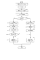
以下、掲示板メッセージをユーザに再通知するための処理の流れについて説明する。図5、図6、図7、図8、図9および図10は掲示板メッセージをユーザに再通知するための制御を示すフローチャートであり、動作詳細については後述する。 Hereinafter, a flow of processing for re-notifying the user of the bulletin board message will be described. 5, FIG. 6, FIG. 7, FIG. 8, FIG. 9 and FIG. 10 are flowcharts showing the control for re-notifying the user of the bulletin board message. Details of the operation will be described later.
図11は、図1に示した複合機300上で動作する認証アプリケーション2008が参照するデータの一例を示すデータ構成図であり、データは、複合機300上で動作するメッセージ受信モジュール2007によって、データファイル2011に書き込まれる。
FIG. 11 is a data configuration diagram illustrating an example of data referred to by the
図12は、掲示板メッセージを持つ、複合機300上で動作する認証アプリケーション2008が図3の操作部308に表示されている一例を示す図である。
FIG. 12 is a diagram illustrating an example in which an
図13は、掲示板メッセージを持たない、複合機300上で動作する認証アプリケーション2008が図3の操作部308に表示されている一例を示す図である。
FIG. 13 is a diagram showing an example in which an
図14は、複合機300上で動作する認証アプリケーション2008の掲示板メッセージが、複合機認証システムにログインした後に、図3の操作部308に、再通知され表示されている一例を示す図である。ユーザは、再通知されたメッセージを閉じる(画面を閉じる)ことによって、複合機300の操作が実施可能となる。内容については、本発明でその仕組みを提供しており、動作詳細については、図5、図6、図7、図8、図9および図10のフローチャートの説明において後述する。
FIG. 14 is a diagram illustrating an example in which a bulletin board message of the
図15は、複合機300上で動作する認証アプリケーション2008の掲示板メッセージが、複合機認証システムにログインした後に、図3の操作部308に、再通知されない一例を示す図である。ユーザは、即座に複合機300の操作が実施可能となる。内容については、図5、図6、図7、図8、図9および図10のフローチャートの説明において後述する。
FIG. 15 is a diagram illustrating an example in which the bulletin board message of the
図16は、メッセージ送信クライアント200の一例を示す図である。ここで示す情報をメッセージ受信モジュール2007へ送信する。内容については、図5、図7および図9のフローチャートの説明において後述する。
FIG. 16 is a diagram illustrating an example of the
次に、図5を用いて、本発明の実施形態におけるメッセージ送信クライアント200とメッセージ受信モジュール2007におけるメッセージ再通知のためのアラートフラグに関する処理の流れについて説明する。
Next, a flow of processing related to an alert flag for message re-notification in the
ステップS100では、メッセージ送信クライアント200は、予め設定されたメッセージ送信時刻が到来したか否かを判断する。
In step S100, the
メッセージ送信時刻が到来したと判断した場合(ステップS100:YES)は、処理をステップS101に移行する。 If it is determined that the message transmission time has arrived (step S100: YES), the process proceeds to step S101.
メッセージ送信時刻が到来していないと判断した場合(ステップS100:NO)は、メッセージ送信時刻が到来するまで待機する。 If it is determined that the message transmission time has not arrived (step S100: NO), the process waits until the message transmission time arrives.
ステップS101では、メッセージ送信クライアント200は、複合機300のメッセージ受信モジュール2007と通信が可能であるか否かを確認する。
In step S <b> 101, the
通信が可能であると判断すると(ステップS101:YES)、処理をステップS102に移行する。 If it is determined that communication is possible (step S101: YES), the process proceeds to step S102.
通信が不可能であると判断すると(ステップS101:NO)、本フローチャートの処理を終了し、再度、設定されたメッセージ送信時刻が到来するまで待機する。 If it is determined that communication is impossible (step S101: NO), the process of this flowchart is terminated, and the process waits again until the set message transmission time arrives.
ステップS102では、メッセージ送信クライアント200は、メッセージ受信モジュール2007に送信する掲示板メッセージが再通知する必要があるメッセージであるか否かの情報(アラートフラグがONであるかOFFであるか)を取得する。
In step S102, the
ステップS103では、メッセージ送信クライアント200は、ステップS102で取得した情報(アラートフラグ)を複合機300のメッセージ受信モジュール2007に送信する。
In step S103, the
ステップS104では、メッセージ受信モジュール2007は、ステップS103でメッセージ送信クライアント200から送信されたアラートフラグを受信する。
In step S104, the
ステップS105では、メッセージ受信モジュール2007は、ステップS104で受信したアラートフラグが「ON」であるか「OFF」であるかを判断する。
In step S105, the
ステップS105にてアラートフラグが「ON」であると判断された場合(ステップS105:ON)は、処理をステップS107に移行する If it is determined in step S105 that the alert flag is “ON” (step S105: ON), the process proceeds to step S107.
ステップS105にてアラートフラグが「OFF」であると判断された場合(ステップS105:NO)は、処理をステップS106に移行する。 If it is determined in step S105 that the alert flag is “OFF” (step S105: NO), the process proceeds to step S106.
ステップS106では、メッセージ受信モジュール2007は、図11におけるデータファイル2011にアラートフラグを「OFF」で情報を書き込み、処理をステップS108に移行する。
In step S106, the
ステップS107では、メッセージ受信モジュール2007は、図11におけるデータファイル2011にアラートフラグを「ON」で情報を書き込み、処理をステップS108に移行する。
In step S107, the
ステップS108では、メッセージ受信モジュール2007は、メッセージ送信クライアントに対して、処理結果を返信する。
In step S108, the
ステップS109では、メッセージ送信クライアント200は、ステップS108でメッセージ受信モジュールから送信された処理結果を受信する。
In step S109, the
ステップ110では、メッセージ送信クライアント200は、ステップS109で受信した処理結果がエラーであるか否かを判断する。例えば、メッセージ受信モジュール2007がデータファイル2011に情報書き込みを失敗した場合などがエラーに該当する。
In
ステップS110でエラーであると判断した場合(ステップS110:YES)は、処理をステップS111へ移行する。 If it is determined in step S110 that an error has occurred (step S110: YES), the process proceeds to step S111.
エラーではないと判断した場合(ステップS110:NO)は、処理をステップS112へ移行する。 If it is determined that there is no error (step S110: NO), the process proceeds to step S112.
ステップS111では、メッセージ送信クライアント200は、エラーメッセージを表示し、本フローチャートに示す処理を終了する。なお、次のメッセージ送信時刻が到来すると、再度本フローチャートに示す処理が開始される。
In step S111, the
ステップS112では、メッセージ送信クライアント200は、掲示板メッセージをメッセージ受信モジュール2007へ送信する。
In step S112, the
ステップS113では、メッセージ受信モジュール2007は、ステップS112でメッセージ送信クライアントから送信された掲示板メッセージを受信する。なお、メッセージが存在しない場合は、空メッセージを受信する。
In step S113, the
ステップS114では、メッセージ受信モジュール2007は、ステップS113で受信した掲示板メッセージを、図11におけるデータファイル2011の「掲示板メッセージ行1」、「掲示板メッセージ行2」、「掲示板メッセージ行3」、「掲示板メッセージ行4」へ書き込む。なお、ステップS113で受信した掲示板メッセージが空メッセージの場合は、「「掲示板メッセージ行1」、「掲示板メッセージ行2」、「掲示板メッセージ行3」、「掲示板メッセージ行4」に空文字を書き込む。
In step S114, the
ステップS115では、メッセージ受信モジュール2007は、メッセージ送信クライアント200に対して、処理結果を送信する。
In step S <b> 115, the
ステップS116では、メッセージ送信クライアント200は、ステップS115でメッセージ受信モジュール2007から送信された処理結果を受信する。
In step S116, the
ステップS117では、メッセージ送信クライアント200は、ステップS116で受信した処理結果がエラー(例えばメッセージ受信モジュール2007がデータファイル2011に情報書き込みを失敗した等)であるか否かを判断する。
In step S117, the
エラーであると判断した場合(ステップS117:YES)は、処理をステップS118に移行し、エラーメッセージを表示して(ステップS118)、本フローチャートに示す処理を終了する。 If it is determined that an error has occurred (step S117: YES), the process proceeds to step S118, an error message is displayed (step S118), and the process shown in this flowchart is terminated.
エラーではないと判断した場合(ステップS117:NO)は、本フローチャートの処理を終了する。 If it is determined that there is no error (step S117: NO), the process of this flowchart is terminated.
なお、次のメッセージ送信時刻が到来すると、再度本フローチャートに示す処理が開始される。 When the next message transmission time comes, the process shown in this flowchart is started again.
次に、図6を用いて、複合機300における認証アプリケーション2008において実行される、アラートフラグを用いた処理および掲示板メッセージの再通知について説明する。
Next, processing using an alert flag and bulletin board message re-notification executed in the
ステップS200では、ユーザの電源ON操作などにより、複合機300が起動される。そして、複合機300が起動すると処理がステップS201に移行する。
In step S200, the
ステップS201では、複合機300の起動時に、図11におけるデータファイル2011の「掲示板メッセージ行1」、「掲示板メッセージ行2」、「掲示板メッセージ行3」、「掲示板メッセージ行4」および「アラートフラグ」の情報を取得する。
In step S201, at the time of activation of the
ステップS202では、ステップS201で取得した情報のうち「掲示板メッセージ行1」、「掲示板メッセージ行2」、「掲示板メッセージ行3」、「掲示板メッセージ行4」のいずれかにメッセージが存在するか否かを判断する。
In step S202, whether or not there is a message in any of “Bulletin
いずれかにメッセージが存在すると判断した場合(ステップS202:YES)は、処理をステップS203に移行する。 If it is determined that there is a message in any one (step S202: YES), the process proceeds to step S203.
いずれにもメッセージが存在しない(空メッセージである)と判断した場合(ステップS202:NO)は、処理をステップS204に移行する。
まず、メッセージが存在する場合の処理について説明する。
If it is determined that there is no message (empty message) in either case (step S202: NO), the process proceeds to step S204.
First, processing when a message exists will be described.
ステップS203では、複合機300の操作部308に表示される認証アプリケーション2008のトップ画面に掲示板メッセージを表示する。なお表示される掲示板メッセージの一例を図12に示す。
In step S203, a bulletin board message is displayed on the top screen of the
ステップS205では、複合機300の認証アプリケーション2008は認証が行われるまで待機する。ユーザによりICカードがカードリーダにかざされる等の処理があった場合には、処理をステップS207に移行する。
In step S205, the
ステップS207では、複合機300における認証アプリケーション2008は、認証処理を実行する。
In step S207, the
なお、認証処理とは、複合機300のカードリーダ319にかざされたICカードから、カード情報等の識別情報を取得し、取得した識別情報を認証サーバ500に送信し、認証サーバによる認証処理(認証サーバが記憶する認証用テーブルと識別情報とを照合する処理)の結果を受信する処理をいう。
The authentication process refers to acquiring identification information such as card information from an IC card held over the
なお、本実施例においては、認証に成功した旨の結果を受信することを前提としている。認証に失敗した場合(認証サーバ500の認証用テーブルに送信した識別情報が登録されていない場合や、認証サーバ500との通信が不可能である場合等)には、ステップS209以降の処理は実行されず、エラーとして本フローチャートの処理を終了する。
In the present embodiment, it is assumed that a result indicating that the authentication is successful is received. When authentication fails (when the identification information transmitted to the authentication table of the
ステップS209では、複合機300は、ステップS201で取得したメッセージに含まれる「アラートフラグ」の状態を確認する。 In step S209, the multifunction peripheral 300 checks the state of the “alert flag” included in the message acquired in step S201.
「アラートフラグ」が「ON」である場合(ステップS209:YES)には、処理をステップS210に移行する。「アラートフラグ」が「OFF」である場合(ステップS209:NO) には、処理をステップS211に移行する。 If the “alert flag” is “ON” (step S209: YES), the process proceeds to step S210. If the “alert flag” is “OFF” (step S209: NO), the process proceeds to step S211.
ステップS210では、複合機300における認証アプリケーション2008による認証処理が成功した後、操作部に図14に一例を示す画面(掲示板メッセージ)を表示し、掲示板メッセージの再通知を行う。
In step S210, after the authentication process by the
なお、掲示板メッセージの再通知内容を閉じると、操作部は、図15に一例を示す画面に移行し、本フローチャートに示す処理を終了する。 When the notice content of the bulletin board message is closed, the operation unit shifts to a screen illustrated in FIG. 15 and ends the processing illustrated in this flowchart.
次に、メッセージが存在しない場合の処理について説明する。 Next, processing when there is no message will be described.
ステップS204では、複合機300の表示部に認証アプリケーション2008のトップ画面に図13に一例を示す画面(掲示板メッセージが表示されていない画面)を表示する。
In step S <b> 204, a screen (an example in which a bulletin board message is not displayed) shown in FIG. 13 is displayed on the top screen of the
ステップS206では、複合機300の認証アプリケーション2008は認証が行われるまで待機する。ユーザによりICカードがカードリーダにかざされる等の処理があった場合には、処理をステップS208に移行する。
In step S206, the
ステップS208では、複合機300における認証アプリケーション2008は、認証処理を実行する(ステップS207で説明した処理と同じ処理である)。
In step S208, the
ステップS211では、ステップS208で複合機300における認証アプリケーション2008による認証処理が実行されると、複合機300の表示部に図15に一例を示す画面(掲示板メッセージを再通知しない画面)を表示する。
そして、本フローチャートの処理を終了する。
In step S211, when the authentication process by the
And the process of this flowchart is complete | finished.
図5および図6に示す処理を実行することにより、アラートフラグが設定された掲示板メッセージについては、認証画面(図12)だけでなく認証処理が行われ複合機300にログインした後にも再度掲示板メッセージが表示されることになる(図14)。これにより、ユーザに対して確実に伝えたいメッセージを伝えることが可能となる。
By executing the processing shown in FIG. 5 and FIG. 6, the bulletin board message in which the alert flag is set is not only the authentication screen (FIG. 12), but also after the authentication process is performed and the
次に、図7のフローチャートを用いて、本発明におけるメッセージ送信クライアント200とメッセージ受信モジュール2007におけるメッセージ再通知のためのアラート時刻設定に関する処理について説明する。
Next, processing related to alert time setting for message re-notification in the
なお、図7のフローチャートでは、本来、メッセージ送信クライアント200により掲示板メッセージの送信も行われるが、掲示板メッセージの送信処理については図5に示す処理と同様(ステップS112〜S118に相当)であるため、ここでは説明を省略する。
In the flowchart of FIG. 7, the
ステップS300では、メッセージ送信クライアント200は、予め設定されたメッセージ送信時刻が到来したか否かを判断する。
In step S300, the
メッセージ送信時刻が到来したと判断した場合(ステップS300:YES)は、処理をステップS301に移行する。 If it is determined that the message transmission time has arrived (step S300: YES), the process proceeds to step S301.
メッセージ送信時刻が到来していないと判断した場合(ステップS300:NO)は、メッセージ送信時刻が到来するまで待機する。 If it is determined that the message transmission time has not arrived (step S300: NO), the process waits until the message transmission time arrives.
ステップS301では、メッセージ送信クライアント200は、複合機300のメッセージ受信モジュール2007と通信が可能であるか否かを確認する。
In step S <b> 301, the
通信が可能であると判断すると(ステップS301:YES)、処理をステップS302に移行する。 If it is determined that communication is possible (step S301: YES), the process proceeds to step S302.
通信が不可能であると判断すると(ステップS301:NO)、本フローチャートの処理を終了し、再度、設定されたメッセージ送信時刻が到来するまで待機する。 If it is determined that communication is impossible (step S301: NO), the process of this flowchart is terminated, and the process waits again until the set message transmission time arrives.
ステップS302では、メッセージ送信クライアント200は、「アラート時刻」をメッセージ受信モジュールに送信する。
In step S302, the
なお、「アラート時刻」とは、図16に示す「アラート開始時刻」および「アラート終了時刻」の双方を示すものである。 The “alert time” indicates both “alert start time” and “alert end time” shown in FIG.
ステップS303では、メッセージ受信モジュール2007は、ステップS302でメッセージ送信クライアント200から送信されたアラート時刻を受信する。
In step S303, the
ステップS304では、メッセージ受信モジュール2007は、図11に示すデータファイル2011に、ステップS303で受信した「アラート開始時刻」「アラート終了時刻」の情報を書き込む。
In step S304, the
ステップS305では、メッセージ受信モジュール2007は、メッセージ送信クライアント200に対して、処理結果を返信する。
In step S <b> 305, the
ステップS306では、メッセージ送信クライアント200は、ステップS305でメッセージ送信クライアント200から送信された処理結果を受信する。
In step S306, the
ステップS307では、メッセージ送信クライアント200は、ステップS306で受信した処理結果がエラーであるか否かを判断する。なお、エラーである場合とは、例えばステップS304においてメッセージ受信モジュール2007がデータファイル2011に情報の書き込みを失敗した場合などがある。
In step S307, the
処理結果がエラーであると判断した場合(ステップS307:YES)は、処理をステップS308に移行し、処理結果がエラーである旨のメッセージを表示する。そして、本フローチャートの処理を終了し、次回のメッセージ送信時刻が到来するまで待機する。 If it is determined that the processing result is an error (step S307: YES), the process proceeds to step S308, and a message indicating that the processing result is an error is displayed. Then, the processing of this flowchart is ended, and the process waits until the next message transmission time comes.
処理結果がエラーではないと判断した場合(ステップS307:NO)は、本フローチャートの処理を終了し、次回のメッセージ送信時刻が到来するまで待機する。 If it is determined that the processing result is not an error (step S307: NO), the processing of this flowchart is terminated, and the process waits until the next message transmission time comes.
次に、図8に示すフローチャートを用いて、複合機300における認証アプリケーション2008による、アラート時刻(アラート開始時刻およびアラート終了時刻)を用いた処理および掲示板メッセージの再通知処理について説明する。
Next, processing using the alert time (alert start time and alert end time) and bulletin board message re-notification processing by the
なお、図8に示すフローチャートでは本来、掲示板メッセージが存在するか否かによって、掲示板メッセージの再通知が実施されるか否かが決定するが、掲示板メッセージの存在を判断する動作については、図6に示すフローチャートと同様(掲示板メッセージが存在しない場合には、アラート時刻にかかわらず掲示板メッセージは再通知されない)であるため、ここではその処理の説明については省略する。 In the flowchart shown in FIG. 8, it is originally determined whether or not the bulletin board message is re-notified depending on whether or not the bulletin board message exists. (The bulletin board message is not re-notified regardless of the alert time when there is no bulletin board message), and the description of the processing is omitted here.
ステップS400では、ユーザの電源ON操作などにより、複合機300が起動される。そして、複合機300が起動すると処理がステップS401に移行する。
In step S400, the
ステップS401では、複合機における認証アプリケーション2008は、認証が行われるまで待機する。ユーザによりICカードがカードリーダにかざされる等の処理があった場合には、処理をステップS402に移行する。
In step S401, the
ステップS402では、複合機300における認証アプリケーション2008は、認証処理を実行する。
In step S402, the
ステップS403では、複合機300の起動時に、図11に示すデータファイル2011の「アラート開始時刻」および「アラート終了時刻」を取得する。 In step S403, the “alert start time” and “alert end time” of the data file 2011 shown in FIG.
ステップS404では、複合機300は、現在時刻が「アラート開始時刻」と「アラート終了時刻」との間であるか否かを判断する。
In step S404, the
現在時刻が「アラート開始時刻」と「アラート終了時刻」との間にあると判断した場合(ステップS404:YES)は、処理をステップS405に移行する。 If it is determined that the current time is between “alert start time” and “alert end time” (step S404: YES), the process proceeds to step S405.
現在時刻が「アラート開始時刻」と「アラート終了時刻」との間ではないと判断した場合(ステップS404:NO)は、処理をステップS406に移行する。 If it is determined that the current time is not between “alert start time” and “alert end time” (step S404: NO), the process proceeds to step S406.
ステップS405では、複合機300は、認証アプリケーション2008による認証処理が成功すると、操作部に掲示板メッセージを再通知する(図14に示す画面を表示する)。そして、表示された掲示板メッセージの再通知内容が閉じられると、表示部に図15に示す画面を表示し、ステップS407に処理を移行し、本フローチャートに示す処理終了する。
In step S405, when the authentication process by the
ステップS406では、複合機300は、認証アプリケーション2008による認証処理が成功すると、表示部に図15に示す画面を表示し、ステップS407に処理を移行し、本フローチャートに示す処理終了する。
In step S406, when the authentication process by the
図7および図8に示す処理を実行することにより、アラート時刻内にログインされた場合には、認証画面(図12)だけでなく認証処理が行われ複合機300にログインした後にも再度掲示板メッセージが表示されることになる(図14)。これにより、ユーザに対して確実に伝えたいメッセージを伝えることが可能となる。
When logged in within the alert time by executing the processes shown in FIGS. 7 and 8, not only the authentication screen (FIG. 12) but also the authentication process is performed, and the bulletin board message is again displayed after logging in to the
次に、図9に示すフローチャートを用いて、本発明におけるメッセージ送信クライアント200とメッセージ受信モジュール2007におけるカード検知までの時間とメッセージ再通知に関する処理について説明する。
Next, processing relating to the time until card detection and message re-notification in the
なお、図9に示すフローチャートでは、本来、メッセージ送信クライアント200により、掲示板メッセージの送信も行われるが、図5で示すフローチャートと同様(ステップS112〜S118に相当)であるため、ここではその処理についての説明は省略する。
In the flowchart shown in FIG. 9, the
ステップS500では、メッセージ送信クライアント200は、予め設定されたメッセージ送信時刻が到来したか否かを判断する。
In step S500, the
メッセージ送信時刻が到来したと判断した場合(ステップS500:YES)は、処理をステップS501に移行する。 If it is determined that the message transmission time has arrived (step S500: YES), the process proceeds to step S501.
メッセージ送信時刻が到来していないと判断した場合(ステップS500:NO)は、メッセージ送信時刻が到来するまで待機する。 If it is determined that the message transmission time has not arrived (step S500: NO), the process waits until the message transmission time arrives.
ステップS501では、メッセージ送信クライアント200は、複合機300のメッセージ受信モジュール2007と通信が可能であるか否かを確認する。
In step S <b> 501, the
通信が可能であると判断すると(ステップS501:YES)、処理をステップS502に移行する。 If it is determined that communication is possible (step S501: YES), the process proceeds to step S502.
通信が不可能であると判断すると(ステップS501:NO)、本フローチャートの処理を終了し、再度、設定されたメッセージ送信時刻が到来するまで待機する。 If it is determined that communication is impossible (step S501: NO), the processing of this flowchart is terminated, and the process waits again until the set message transmission time arrives.
ステップS502では、メッセージ送信クライアント200は、「カード検知までの閾値」をメッセージ受信モジュールに送信する。
In step S502, the
なお、「カード検知までの閾値」とは、図16に示す値であり、人検知時刻(複合機300の周辺に人がいることを検知した時刻)からカード検知時刻(ユーザにより認証処理のためにICカードがカードリーダ319にかざされた(認証処理が開始された)時刻)までの時間により掲示板メッセージを再通知するか否かを決定するための閾値である。 Note that the “threshold value until card detection” is the value shown in FIG. 16, and the card detection time (for the authentication process by the user) from the person detection time (the time when it is detected that there is a person around the MFP 300) This is a threshold value for determining whether or not to re-notify the bulletin board message based on the time until the IC card is held over the card reader 319 (the time when the authentication process is started).
ステップS503では、メッセージ受信モジュール2007は、ステップS502でメッセージ送信クライアント200から送信された「カード検知までの閾値」を受信する。
In step S503, the
ステップS504では、メッセージ受信モジュール2007は、図11におけるデータファイル2011に「カード検知までの閾値」の情報を書き込み、ステップS505に処理を移行する。
In step S504, the
ステップS505では、メッセージ受信モジュール2007は、処理結果をメッセージ送信クライアント200に対して送信する。
In step S505, the
ステップS506では、メッセージ送信クライアント200は、ステップS505でメッセージ送信クライアント200から送信された処理結果を受信する。
In step S506, the
ステップS507では、メッセージ送信クライアント200は、ステップS506で受信した処理結果がエラーであるか否かを判断する。なお、エラーである場合とは、例えばステップS504においてメッセージ受信モジュール2007がデータファイル2011に情報の書き込みを失敗した場合などがある。
In step S507, the
処理結果がエラーであると判断した場合(ステップS507:YES)は、処理をステップS508に移行し、処理結果がエラーである旨のメッセージを表示する。そして、本フローチャートの処理を終了し、次回のメッセージ送信時刻が到来するまで待機する。 If it is determined that the processing result is an error (step S507: YES), the process proceeds to step S508, and a message indicating that the processing result is an error is displayed. Then, the processing of this flowchart is ended, and the process waits until the next message transmission time comes.
処理結果がエラーではないと判断した場合(ステップS507:NO)は、本フローチャートの処理を終了し、次回のメッセージ送信時刻が到来するまで待機する。 If it is determined that the processing result is not an error (step S507: NO), the processing of this flowchart is terminated and the process waits until the next message transmission time comes.
次に、図10に示すフローチャートを用いて、複合機300における認証アプリケーション2008により実行されるカード検知までの閾値を用いた処理および掲示板メッセージの再通知について説明する。
Next, processing using a threshold up to card detection executed by the
なお、図10のフローチャートでは、本来、掲示板メッセージが存在するか否かで、掲示板メッセージの再通知が実施されるか否かが決定するが、掲示板メッセージの存在による動作については、図6に示すフローチャートと同様(掲示板メッセージが存在しない場合は、カード検知までの閾値に関わらず、掲示板メッセージは再通知されない)であるため、ここではその処理の説明については省略する。 In the flowchart of FIG. 10, it is originally determined whether or not the notice of the bulletin board message is executed again depending on whether or not the bulletin board message exists. The operation due to the presence of the bulletin board message is shown in FIG. Since this is the same as the flowchart (when there is no bulletin board message, the bulletin board message is not re-notified regardless of the threshold until card detection), the description of the processing is omitted here.
ステップS600において、複合機300は、図3におけるセンサー321が人を検知するまで待機する。センサー321が人を検知した場合は、検知した旨の情報が図3における外部I/F318に伝わり、認証アプリケーション2008が人を検知したことを判別する。そして、処理をステップS601に移行する。なお、センサー321が人を検知したことを判別し、センサー321が検知できる範囲で人が操作し続ける限りは、新たな検知を実施しない。検知したことを判別し、ステップS601に進むのは、センサー321が人を検知していない状態から、センサー321が人を検知した状態に遷移した場合である。
In step S600, the multifunction peripheral 300 waits until the
ステップS601では、複合機300における認証アプリケーション2008は「人検知時刻」(ステップS600でセンサー321が人を検知した時刻)をRAM302に記録し、処理をステップS602に移行する。なお、センサー321が新たに人を検知した際は、新しい「人検知時刻」がRAM302に記録されるものとし、「人検知時刻」は複数保持することができない。つまり、前回の「人検知時刻」は新たに上書きされる。
In step S601, the
ステップS602において、複合機300は、認証アプリケーション2008のログイン状態を確認し、認証アプリケーション2008がログオフ状態にある場合(ステップS602:NO)は、ステップS612に処理を移行する。他方、ログオフ状態にない場合(ログインしている状態)(ステップS602:YES)は、処理をステップS603に移行する。
In step S602, the
ステップS603では、認証アプリケーション2008は、ユーザによりICカードがかざされる操作(認証操作)を待機し、ユーザによる認証操作を検知すると、ステップS604に処理を移行する。
In step S603, the
なお、ユーザの認証操作を待機している間に、センサー321が新たな人を検知し、ステップS601、S602の処理を経て、ステップS603に到達した場合、ステップS603は当該新たなユーザの認証操作を待機する。
If the
ステップS604において、複合機300は、ユーザによりICカードがかざされた時刻(「カード検知時刻」)をRAM302に記録し、ステップS605に処理を移行する。
In step S604, the
なお、本実施例において、RAM302で記録される「カード検知時刻」は複数保持しない。すなわち、前回の「カード検知時刻」は新たに上書きされる。
In this embodiment, a plurality of “card detection times” recorded in the
ステップS605では、複合機300における認証アプリケーション2008の認証処理が実施される。
In step S605, authentication processing of the
ステップS606では、複合機300は、図11におけるデータファイル2011の「カード検知までの閾値」の情報を取得する。
In step S <b> 606, the
ステップS607では、複合機300の認証アプリケーション2008は、RAM302に記録された「カード検知時刻」と「人検知時刻」の差(人を検知してからカードを検知するまでの時間)を算出し、その値がステップS606で取得した「カード検知までの閾値」未満であるかを判断する。
In step S607, the
閾値未満であると判断した場合(ステップS607:NO)は、処理をステップS608に移行する。 If it is determined that the value is less than the threshold (step S607: NO), the process proceeds to step S608.
閾値以上であると判断した場合(ステップS607:YES)は、処理をステップS609に移行する。 If it is determined that the value is equal to or greater than the threshold (step S607: YES), the process proceeds to step S609.
ステップS608では、複合機300は、認証アプリケーション2008による認証処理が成功すると、操作部に掲示板メッセージを再通知する(図14に示す画面を表示する)。そして、表示された掲示板メッセージの再通知内容が閉じられると、表示部に図15に示す画面を表示し、ステップS610に処理を移行する。
In step S608, when the authentication process by the
ステップS609では、複合機300は、認証アプリケーション2008による認証処理が成功すると、表示部に図15に示す画面を表示し、ステップS610に処理を移行する。
In step S609, when the authentication process by the
ステップS611では、複合機300は、RAM302に記録された「カード検知時刻」をリセットする。
In step S <b> 611, the
ステップS612では、複合機300は、RAM302に記録された「人検知時刻」をリセットし、本フローチャートに示す処理を終了する。そして、次の利用者を検知するまで待機する。
In step S612, the
図9および図10に示す処理を実行することにより、複合機300が人を検知してからカードを検知するまでの時間差が閾値以下である場合(すなわち、複合機にログインしたユーザが認証画面に表示された掲示板メッセージを確認せずに認証処理を行った可能性が高い場合)には、認証画面(図12)だけでなく認証処理が行われ複合機300にログインした後にも再度掲示板メッセージが表示されることになる(図14)。これにより、ユーザに対して確実に伝えたいメッセージを伝えることが可能となる。
By executing the processing shown in FIG. 9 and FIG. 10, when the time difference from when the
上述したように、複合機300における認証アプリケーション2008において、掲示板メッセージを再通知する仕組みとして、図5および図6では、アラートフラグを用いる仕組みについて示した。また、図7および図8では、アラート時刻、つまりはアラート開始時刻およびアラート終了時刻を用いる仕組みについて示した。また、図9および図10では、カード検知までの閾値を用いる仕組みについて示した。これらは、それぞれを独立して動作させることで、メッセージ再通知を実現することが可能である。
As described above, in the
また、各仕組みを組み合わせて動作させることでも、メッセージ再通知を実現することが可能である。例えば、アラートフラグとアラート時刻の仕組みを組み合わせて、メッセージ再通知の仕組みを実現する場合は、アラートフラグとアラート時刻の双方がメッセージ再通知の条件を満たす場合に、再通知が実施されるという動作となる。 Further, message re-notification can also be realized by operating each mechanism in combination. For example, when a message re-notification mechanism is realized by combining an alert flag and an alert time mechanism, the re-notification is performed when both the alert flag and the alert time satisfy the message re-notification condition. It becomes.
同様に、アラートフラグとカード検知までの閾値との組み合わせや、アラート時刻とカード検知までの閾値との組み合わせや、全て仕組みの組み合わせによって、メッセージ再通知の仕組みを実現することも可能である。 Similarly, a message re-notification mechanism can be realized by a combination of an alert flag and a threshold until card detection, a combination of an alert time and a threshold until card detection, or a combination of all mechanisms.
なお、上述した各種データの構成及びその内容はこれに限定されるものではなく、用途や目的に応じて、様々な構成や内容で構成されることは言うまでもない。 It should be noted that the configuration and contents of the various data described above are not limited to this, and it goes without saying that the various data and configurations are configured according to the application and purpose.
また、本発明におけるプログラムは、図5〜図10の処理方法をコンピュータが実行可能なプログラムである。なお、本発明におけるプログラムは図5〜図10の各装置の処理方法ごとのプログラムであってもよい。 Moreover, the program in this invention is a program which a computer can perform the processing method of FIGS. The program in the present invention may be a program for each processing method of each apparatus in FIGS.
以上のように、前述した実施形態の機能を実現するプログラムを記録した記録媒体を、システムあるいは装置に供給し、そのシステムあるいは装置のコンピュータ(またはCPUやMPU)が記録媒体に格納されたプログラムを読み出し、実行することによっても本発明の目的が達成されることは言うまでもない。 As described above, a recording medium that records a program that implements the functions of the above-described embodiments is supplied to a system or apparatus, and a computer (or CPU or MPU) of the system or apparatus stores the program stored in the recording medium. It goes without saying that the object of the present invention can also be achieved by reading and executing.
この場合、記録媒体から読み出されたプログラム自体が本発明の新規な機能を実現することになり、そのプログラムを記録した記録媒体は本発明を構成することになる。 In this case, the program itself read from the recording medium realizes the novel function of the present invention, and the recording medium recording the program constitutes the present invention.
プログラムを供給するための記録媒体としては、例えば、フレキシブルディスク、ハードディスク、光ディスク、光磁気ディスク、CD−ROM、CD−R、DVD−ROM、磁気テープ、不揮発性のメモリカード、ROM、EEPROM、シリコンディスク等を用いることが出来る。 As a recording medium for supplying the program, for example, a flexible disk, hard disk, optical disk, magneto-optical disk, CD-ROM, CD-R, DVD-ROM, magnetic tape, nonvolatile memory card, ROM, EEPROM, silicon A disk or the like can be used.
また、コンピュータが読み出したプログラムを実行することにより、前述した実施形態の機能が実現されるだけでなく、そのプログラムの指示に基づき、コンピュータ上で稼働しているOS(オペレーティングシステム)等が実際の処理の一部または全部を行い、その処理によって前述した実施形態の機能が実現される場合も含まれることは言うまでもない。 Further, by executing the program read by the computer, not only the functions of the above-described embodiments are realized, but also an OS (operating system) operating on the computer based on an instruction of the program is actually It goes without saying that a case where the function of the above-described embodiment is realized by performing part or all of the processing and the processing is included.
さらに、記録媒体から読み出されたプログラムが、コンピュータに挿入された機能拡張ボードやコンピュータに接続された機能拡張ユニットに備わるメモリに書き込まれた後、そのプログラムコードの指示に基づき、その機能拡張ボードや機能拡張ユニットに備わるCPU等が実際の処理の一部または全部を行い、その処理によって前述した実施形態の機能が実現される場合も含まれることは言うまでもない。 Furthermore, after the program read from the recording medium is written to the memory provided in the function expansion board inserted into the computer or the function expansion unit connected to the computer, the function expansion board is based on the instructions of the program code. It goes without saying that the case where the CPU or the like provided in the function expansion unit performs part or all of the actual processing and the functions of the above-described embodiments are realized by the processing.
また、本発明は、複数の機器から構成されるシステムに適用しても、ひとつの機器から成る装置に適用しても良い。また、本発明は、システムあるいは装置にプログラムを供給することによって達成される場合にも適応できることは言うまでもない。この場合、本発明を達成するためのプログラムを格納した記録媒体を該システムあるいは装置に読み出すことによって、そのシステムあるいは装置が、本発明の効果を享受することが可能となる。 The present invention may be applied to a system constituted by a plurality of devices or an apparatus constituted by a single device. Needless to say, the present invention can be applied to a case where the present invention is achieved by supplying a program to a system or apparatus. In this case, by reading a recording medium storing a program for achieving the present invention into the system or apparatus, the system or apparatus can enjoy the effects of the present invention.
さらに、本発明を達成するためのプログラムをネットワーク上のサーバ、データベース等から通信プログラムによりダウンロードして読み出すことによって、そのシステムあるいは装置が、本発明の効果を享受することが可能となる。なお、上述した各実施形態およびその変形例を組み合わせた構成も全て本発明に含まれるものである。 Furthermore, by downloading and reading a program for achieving the present invention from a server, database, etc. on a network using a communication program, the system or apparatus can enjoy the effects of the present invention. In addition, all the structures which combined each embodiment mentioned above and its modification are also included in this invention.
100 クライアントPC
200 メッセージ送信クライアント
300 複合機
400 LAN
500 認証サーバ
100 client PC
200
500 Authentication server
Claims (8)
当該画像処理装置で表示するメッセージを記憶するメッセージ記憶手段と、
前記メッセージ記憶手段に記憶されたメッセージを前記認証アプリケーションにより表示される画面に表示するメッセージ表示手段と、
メッセージを再表示するか否かを示す情報を記憶する記憶手段と、
前記メッセージ表示手段により表示したメッセージを認証処理の実行後にも表示するか否かを、前記記憶手段に記憶されたメッセージを再表示するか否かを示す情報に基づき判断する再表示判断手段と、
前記再表示判断手段により認証処理の実行後にも表示すると判断された場合、当該メッセージを認証処理の実行後に表示するメッセージ再表示手段と、
を備えることを特徴とする画像処理装置。 An image processing apparatus configured to be able to install an authentication application for executing processing related to authentication,
Message storage means for storing a message to be displayed on the image processing apparatus;
Message display means for displaying a message stored in the message storage means on a screen displayed by the authentication application;
Storage means for storing information indicating whether to redisplay the message;
Redisplay determination means for determining whether or not to display the message displayed by the message display means even after execution of authentication processing, based on information indicating whether or not to redisplay the message stored in the storage means;
A message redisplay means for displaying the message after the execution of the authentication process when it is determined by the redisplay determination means to be displayed even after the execution of the authentication process;
An image processing apparatus comprising:
前記再表示判断手段は、前記メッセージ毎に記憶された再表示するか否かを示す情報に従い、認証処理の実行後にも当該メッセージを表示するか否かを判断することを特徴とする請求項1に記載の画像処理装置。 The storage means stores information on whether to redisplay for each message,
2. The re-display determining unit determines whether or not to display the message even after execution of an authentication process, according to information indicating whether or not to display again for each message. An image processing apparatus according to 1.
前記人検知手段により人物の存在を検知した時刻を取得する人検知時刻取得手段と、
前記認証処理が開始された時刻を取得する認証時刻取得手段と、
をさらに備え、
前記再表示判断手段は、前記人検知時刻取得手段で取得した人物の存在を検知した時刻と、前記認証時刻取得手段で取得した認証処理が開始された時刻との時間差に基づき、認証処理の実行後にも当該メッセージを表示するか否かを判断することを特徴とする請求項1乃至4のいずれか1項に記載の画像処理装置。 Human detection means for detecting the presence of a person around the image forming apparatus;
Human detection time acquisition means for acquiring the time when the presence of a person is detected by the human detection means;
Authentication time acquisition means for acquiring the time at which the authentication process was started;
Further comprising
The re-display determination unit executes the authentication process based on a time difference between the time when the presence of the person acquired by the person detection time acquisition unit is detected and the time when the authentication process acquired by the authentication time acquisition unit is started. 5. The image processing apparatus according to claim 1, wherein it is determined whether or not to display the message later.
前記画像形成装置のメッセージ表示手段が、前記記憶されたメッセージを前記認証アプリケーションにより表示される画面に表示するメッセージ表示工程と、
前記画像形成装置の再表示判断手段が、前記メッセージ表示工程により表示したメッセージを認証処理の実行後にも表示するか否かを、前記記憶されたメッセージを再表示するか否かを示す情報に基づき判断する再表示判断工程と、
前記画像形成装置のメッセージ再表示手段が、前記再表示判断工程により認証処理の実行後にも表示すると判断された場合、当該メッセージを認証処理の実行後に表示するメッセージ再表示工程と、
を備えることを特徴とする情報処理方法。 An information processing method in an image processing apparatus configured to be able to install an authentication application for executing processing related to authentication, and storing a message to be displayed on the image processing apparatus and information indicating whether or not to redisplay the message. ,
A message display step in which the message display means of the image forming apparatus displays the stored message on a screen displayed by the authentication application;
Based on the information indicating whether or not the redisplay determination unit of the image forming apparatus displays the message displayed in the message display step even after executing the authentication process, and whether or not to redisplay the stored message. Re-display determination process to determine,
A message redisplaying step of displaying the message after executing the authentication process when the message redisplaying unit of the image forming apparatus determines that the message is displayed even after the authentication process is executed by the redisplay determining step;
An information processing method comprising:
前記画像処理装置のコンピュータを、
前記記憶されたメッセージを前記認証アプリケーションにより表示される画面に表示するメッセージ表示手段と、
前記メッセージ表示手段により表示したメッセージを認証処理の実行後にも表示するか否かを、前記記憶手段に記憶されたメッセージを再表示するか否かを示す情報に基づき判断する再表示判断手段と、
前記再表示判断手段により認証処理の実行後にも表示すると判断された場合、当該メッセージを認証処理の実行後に表示するメッセージ再表示手段として機能させることを特徴とするプログラム。
It is a program that can be installed in an authentication application that executes processing related to authentication, and that can be executed in an image processing apparatus that stores a message to be displayed on the image processing apparatus and information indicating whether to redisplay the message. And
A computer of the image processing apparatus;
Message display means for displaying the stored message on a screen displayed by the authentication application;
Redisplay determination means for determining whether or not to display the message displayed by the message display means even after execution of authentication processing, based on information indicating whether or not to redisplay the message stored in the storage means;
A program that functions as message redisplay means for displaying the message after execution of authentication processing when it is determined by the redisplay determination means that it is displayed even after execution of authentication processing.
Priority Applications (1)
| Application Number | Priority Date | Filing Date | Title |
|---|---|---|---|
| JP2011080389A JP5786413B2 (en) | 2011-03-31 | 2011-03-31 | Image forming apparatus, processing method, and program |
Applications Claiming Priority (1)
| Application Number | Priority Date | Filing Date | Title |
|---|---|---|---|
| JP2011080389A JP5786413B2 (en) | 2011-03-31 | 2011-03-31 | Image forming apparatus, processing method, and program |
Publications (3)
| Publication Number | Publication Date |
|---|---|
| JP2012213905A JP2012213905A (en) | 2012-11-08 |
| JP2012213905A5 JP2012213905A5 (en) | 2014-07-31 |
| JP5786413B2 true JP5786413B2 (en) | 2015-09-30 |
Family
ID=47267206
Family Applications (1)
| Application Number | Title | Priority Date | Filing Date |
|---|---|---|---|
| JP2011080389A Active JP5786413B2 (en) | 2011-03-31 | 2011-03-31 | Image forming apparatus, processing method, and program |
Country Status (1)
| Country | Link |
|---|---|
| JP (1) | JP5786413B2 (en) |
Families Citing this family (6)
| Publication number | Priority date | Publication date | Assignee | Title |
|---|---|---|---|---|
| JP5805121B2 (en) * | 2013-03-12 | 2015-11-04 | 京セラドキュメントソリューションズ株式会社 | Electronic device, message display control program, and message management system |
| JP5818835B2 (en) * | 2013-03-12 | 2015-11-18 | 京セラドキュメントソリューションズ株式会社 | Electronic device, message display control program, and message management system |
| JP6128905B2 (en) * | 2013-03-12 | 2017-05-17 | 京セラドキュメントソリューションズ株式会社 | Electronic device and message display control program |
| JP5907925B2 (en) * | 2013-04-18 | 2016-04-26 | 京セラドキュメントソリューションズ株式会社 | Device management system, electronic device, device management program, and device management method |
| JP6639430B2 (en) | 2017-01-31 | 2020-02-05 | キヤノン株式会社 | Information processing apparatus, control method, and program |
| JP6833759B2 (en) * | 2018-05-14 | 2021-02-24 | キヤノン株式会社 | Image forming apparatus and its control method |
Family Cites Families (6)
| Publication number | Priority date | Publication date | Assignee | Title |
|---|---|---|---|---|
| JP3174650B2 (en) * | 1992-11-20 | 2001-06-11 | キヤノン株式会社 | Image forming apparatus and control method of image forming apparatus |
| JP3492332B2 (en) * | 2000-06-13 | 2004-02-03 | キヤノン株式会社 | Image processing apparatus having bulletin board function, control method therefor, program, and storage medium |
| GB2420880A (en) * | 2004-11-26 | 2006-06-07 | Ibm | Inhibiting overlooking notifications in applications |
| JP2007088665A (en) * | 2005-09-21 | 2007-04-05 | Fuji Xerox Co Ltd | Information display system |
| JP2009061709A (en) * | 2007-09-07 | 2009-03-26 | Seiko Epson Corp | Tape printing system and tape cartridge |
| JP4820438B2 (en) * | 2009-08-03 | 2011-11-24 | シャープ株式会社 | Display screen control system for control server and multifunction machine |
-
2011
- 2011-03-31 JP JP2011080389A patent/JP5786413B2/en active Active
Also Published As
| Publication number | Publication date |
|---|---|
| JP2012213905A (en) | 2012-11-08 |
Similar Documents
| Publication | Publication Date | Title |
|---|---|---|
| JP4197188B2 (en) | Print management server, print system, print management server control method, print system control method, and program | |
| US10694057B2 (en) | Apparatus, method and storage medium that stores program | |
| JP5786413B2 (en) | Image forming apparatus, processing method, and program | |
| US8988699B2 (en) | Device, information processing apparatus, information processing system, control method, and program | |
| JP2010108348A (en) | Image forming apparatus, information processing system, processing method thereof and program | |
| US8863264B2 (en) | Image forming apparatus, controlling method and program | |
| JP4425238B2 (en) | PRINT SYSTEM, PRINT MANAGEMENT SERVER, PRINTING DEVICE, PRINT SYSTEM CONTROL METHOD, PRINT MANAGEMENT SERVER CONTROL METHOD, PRINT DEVICE CONTROL METHOD, AND PROGRAM | |
| JP4998965B2 (en) | Image forming apparatus, information processing method, and program | |
| JP5637078B2 (en) | Image forming apparatus, image forming system, control method thereof, and program | |
| JP5177673B2 (en) | Image forming apparatus, information processing system, processing method thereof, and program | |
| JP2011029848A (en) | Image forming device, information processing method, and program therefor | |
| JP5673077B2 (en) | Image processing apparatus, processing method thereof, and program. | |
| JP5954104B2 (en) | Print management apparatus, control method for print management apparatus, print management system and program | |
| JP5305160B2 (en) | Image forming apparatus, processing method thereof, and program | |
| JP5387543B2 (en) | Image forming apparatus, information processing method, and program | |
| JP2013123805A (en) | Image forming device, print server, print management system, control method, and program | |
| JP7161826B2 (en) | PRINTING DEVICE, CONTROL METHOD, AND PROGRAM | |
| JP5266007B2 (en) | Information processing apparatus, authentication server, information processing system, control method, program | |
| JP2011043979A (en) | Printing system, control method of the same, and program | |
| JP2013006329A (en) | Image processor, processing method, and program | |
| JP2017154319A (en) | Control system, method for processing the same and program | |
| JP5565284B2 (en) | Image forming apparatus, information processing method, and program | |
| JP5750660B2 (en) | Image forming apparatus, information processing method, and program | |
| JP2019133321A (en) | Image processing apparatus, information processing system, information processing method, and program | |
| JP2014015015A (en) | Image forming system, image forming apparatus and method for controlling the same, and program |
Legal Events
| Date | Code | Title | Description |
|---|---|---|---|
| RD03 | Notification of appointment of power of attorney |
Free format text: JAPANESE INTERMEDIATE CODE: A7423 Effective date: 20130531 |
|
| RD04 | Notification of resignation of power of attorney |
Free format text: JAPANESE INTERMEDIATE CODE: A7424 Effective date: 20130531 |
|
| A621 | Written request for application examination |
Free format text: JAPANESE INTERMEDIATE CODE: A621 Effective date: 20140328 |
|
| A521 | Request for written amendment filed |
Free format text: JAPANESE INTERMEDIATE CODE: A523 Effective date: 20140616 |
|
| A977 | Report on retrieval |
Free format text: JAPANESE INTERMEDIATE CODE: A971007 Effective date: 20150209 |
|
| A131 | Notification of reasons for refusal |
Free format text: JAPANESE INTERMEDIATE CODE: A131 Effective date: 20150217 |
|
| A711 | Notification of change in applicant |
Free format text: JAPANESE INTERMEDIATE CODE: A711 Effective date: 20150410 |
|
| A521 | Request for written amendment filed |
Free format text: JAPANESE INTERMEDIATE CODE: A523 Effective date: 20150413 |
|
| A521 | Request for written amendment filed |
Free format text: JAPANESE INTERMEDIATE CODE: A821 Effective date: 20150416 |
|
| TRDD | Decision of grant or rejection written | ||
| A01 | Written decision to grant a patent or to grant a registration (utility model) |
Free format text: JAPANESE INTERMEDIATE CODE: A01 Effective date: 20150630 |
|
| A61 | First payment of annual fees (during grant procedure) |
Free format text: JAPANESE INTERMEDIATE CODE: A61 Effective date: 20150713 |
|
| R150 | Certificate of patent or registration of utility model |
Ref document number: 5786413 Country of ref document: JP Free format text: JAPANESE INTERMEDIATE CODE: R150 |
|
| R250 | Receipt of annual fees |
Free format text: JAPANESE INTERMEDIATE CODE: R250 |
|
| R250 | Receipt of annual fees |
Free format text: JAPANESE INTERMEDIATE CODE: R250 |
|
| R250 | Receipt of annual fees |
Free format text: JAPANESE INTERMEDIATE CODE: R250 |
|
| S531 | Written request for registration of change of domicile |
Free format text: JAPANESE INTERMEDIATE CODE: R313531 |
|
| R350 | Written notification of registration of transfer |
Free format text: JAPANESE INTERMEDIATE CODE: R350 |
|
| R250 | Receipt of annual fees |
Free format text: JAPANESE INTERMEDIATE CODE: R250 |
|
| R250 | Receipt of annual fees |
Free format text: JAPANESE INTERMEDIATE CODE: R250 |
|
| R250 | Receipt of annual fees |
Free format text: JAPANESE INTERMEDIATE CODE: R250 |
|
| R250 | Receipt of annual fees |
Free format text: JAPANESE INTERMEDIATE CODE: R250 |