JP5783966B2 - Underwater sliding member, underwater sliding member manufacturing method, and hydraulic machine - Google Patents
Underwater sliding member, underwater sliding member manufacturing method, and hydraulic machine Download PDFInfo
- Publication number
- JP5783966B2 JP5783966B2 JP2012165761A JP2012165761A JP5783966B2 JP 5783966 B2 JP5783966 B2 JP 5783966B2 JP 2012165761 A JP2012165761 A JP 2012165761A JP 2012165761 A JP2012165761 A JP 2012165761A JP 5783966 B2 JP5783966 B2 JP 5783966B2
- Authority
- JP
- Japan
- Prior art keywords
- sliding member
- underwater
- layer
- base material
- underwater sliding
- Prior art date
- Legal status (The legal status is an assumption and is not a legal conclusion. Google has not performed a legal analysis and makes no representation as to the accuracy of the status listed.)
- Active
Links
Images


Classifications
-
- F—MECHANICAL ENGINEERING; LIGHTING; HEATING; WEAPONS; BLASTING
- F16—ENGINEERING ELEMENTS AND UNITS; GENERAL MEASURES FOR PRODUCING AND MAINTAINING EFFECTIVE FUNCTIONING OF MACHINES OR INSTALLATIONS; THERMAL INSULATION IN GENERAL
- F16C—SHAFTS; FLEXIBLE SHAFTS; ELEMENTS OR CRANKSHAFT MECHANISMS; ROTARY BODIES OTHER THAN GEARING ELEMENTS; BEARINGS
- F16C33/00—Parts of bearings; Special methods for making bearings or parts thereof
- F16C33/02—Parts of sliding-contact bearings
- F16C33/04—Brasses; Bushes; Linings
- F16C33/20—Sliding surface consisting mainly of plastics
- F16C33/208—Methods of manufacture, e.g. shaping, applying coatings
-
- B—PERFORMING OPERATIONS; TRANSPORTING
- B23—MACHINE TOOLS; METAL-WORKING NOT OTHERWISE PROVIDED FOR
- B23K—SOLDERING OR UNSOLDERING; WELDING; CLADDING OR PLATING BY SOLDERING OR WELDING; CUTTING BY APPLYING HEAT LOCALLY, e.g. FLAME CUTTING; WORKING BY LASER BEAM
- B23K35/00—Rods, electrodes, materials, or media, for use in soldering, welding, or cutting
- B23K35/001—Interlayers, transition pieces for metallurgical bonding of workpieces
- B23K35/004—Interlayers, transition pieces for metallurgical bonding of workpieces at least one of the workpieces being of a metal of the iron group
-
- B—PERFORMING OPERATIONS; TRANSPORTING
- B23—MACHINE TOOLS; METAL-WORKING NOT OTHERWISE PROVIDED FOR
- B23K—SOLDERING OR UNSOLDERING; WELDING; CLADDING OR PLATING BY SOLDERING OR WELDING; CUTTING BY APPLYING HEAT LOCALLY, e.g. FLAME CUTTING; WORKING BY LASER BEAM
- B23K35/00—Rods, electrodes, materials, or media, for use in soldering, welding, or cutting
- B23K35/22—Rods, electrodes, materials, or media, for use in soldering, welding, or cutting characterised by the composition or nature of the material
- B23K35/24—Selection of soldering or welding materials proper
- B23K35/30—Selection of soldering or welding materials proper with the principal constituent melting at less than 1550 degrees C
- B23K35/302—Cu as the principal constituent
-
- B—PERFORMING OPERATIONS; TRANSPORTING
- B32—LAYERED PRODUCTS
- B32B—LAYERED PRODUCTS, i.e. PRODUCTS BUILT-UP OF STRATA OF FLAT OR NON-FLAT, e.g. CELLULAR OR HONEYCOMB, FORM
- B32B15/00—Layered products comprising a layer of metal
- B32B15/01—Layered products comprising a layer of metal all layers being exclusively metallic
- B32B15/013—Layered products comprising a layer of metal all layers being exclusively metallic one layer being formed of an iron alloy or steel, another layer being formed of a metal other than iron or aluminium
- B32B15/015—Layered products comprising a layer of metal all layers being exclusively metallic one layer being formed of an iron alloy or steel, another layer being formed of a metal other than iron or aluminium the said other metal being copper or nickel or an alloy thereof
-
- B—PERFORMING OPERATIONS; TRANSPORTING
- B32—LAYERED PRODUCTS
- B32B—LAYERED PRODUCTS, i.e. PRODUCTS BUILT-UP OF STRATA OF FLAT OR NON-FLAT, e.g. CELLULAR OR HONEYCOMB, FORM
- B32B15/00—Layered products comprising a layer of metal
- B32B15/04—Layered products comprising a layer of metal comprising metal as the main or only constituent of a layer, which is next to another layer of the same or of a different material
- B32B15/08—Layered products comprising a layer of metal comprising metal as the main or only constituent of a layer, which is next to another layer of the same or of a different material of synthetic resin
-
- B—PERFORMING OPERATIONS; TRANSPORTING
- B32—LAYERED PRODUCTS
- B32B—LAYERED PRODUCTS, i.e. PRODUCTS BUILT-UP OF STRATA OF FLAT OR NON-FLAT, e.g. CELLULAR OR HONEYCOMB, FORM
- B32B15/00—Layered products comprising a layer of metal
- B32B15/18—Layered products comprising a layer of metal comprising iron or steel
-
- B—PERFORMING OPERATIONS; TRANSPORTING
- B32—LAYERED PRODUCTS
- B32B—LAYERED PRODUCTS, i.e. PRODUCTS BUILT-UP OF STRATA OF FLAT OR NON-FLAT, e.g. CELLULAR OR HONEYCOMB, FORM
- B32B27/00—Layered products comprising a layer of synthetic resin
- B32B27/18—Layered products comprising a layer of synthetic resin characterised by the use of special additives
- B32B27/20—Layered products comprising a layer of synthetic resin characterised by the use of special additives using fillers, pigments, thixotroping agents
-
- B—PERFORMING OPERATIONS; TRANSPORTING
- B32—LAYERED PRODUCTS
- B32B—LAYERED PRODUCTS, i.e. PRODUCTS BUILT-UP OF STRATA OF FLAT OR NON-FLAT, e.g. CELLULAR OR HONEYCOMB, FORM
- B32B27/00—Layered products comprising a layer of synthetic resin
- B32B27/32—Layered products comprising a layer of synthetic resin comprising polyolefins
- B32B27/322—Layered products comprising a layer of synthetic resin comprising polyolefins comprising halogenated polyolefins, e.g. PTFE
-
- C—CHEMISTRY; METALLURGY
- C22—METALLURGY; FERROUS OR NON-FERROUS ALLOYS; TREATMENT OF ALLOYS OR NON-FERROUS METALS
- C22C—ALLOYS
- C22C38/00—Ferrous alloys, e.g. steel alloys
- C22C38/02—Ferrous alloys, e.g. steel alloys containing silicon
-
- C—CHEMISTRY; METALLURGY
- C22—METALLURGY; FERROUS OR NON-FERROUS ALLOYS; TREATMENT OF ALLOYS OR NON-FERROUS METALS
- C22C—ALLOYS
- C22C38/00—Ferrous alloys, e.g. steel alloys
- C22C38/04—Ferrous alloys, e.g. steel alloys containing manganese
-
- C—CHEMISTRY; METALLURGY
- C22—METALLURGY; FERROUS OR NON-FERROUS ALLOYS; TREATMENT OF ALLOYS OR NON-FERROUS METALS
- C22C—ALLOYS
- C22C38/00—Ferrous alloys, e.g. steel alloys
- C22C38/18—Ferrous alloys, e.g. steel alloys containing chromium
- C22C38/40—Ferrous alloys, e.g. steel alloys containing chromium with nickel
- C22C38/44—Ferrous alloys, e.g. steel alloys containing chromium with nickel with molybdenum or tungsten
-
- C—CHEMISTRY; METALLURGY
- C22—METALLURGY; FERROUS OR NON-FERROUS ALLOYS; TREATMENT OF ALLOYS OR NON-FERROUS METALS
- C22C—ALLOYS
- C22C9/00—Alloys based on copper
-
- F—MECHANICAL ENGINEERING; LIGHTING; HEATING; WEAPONS; BLASTING
- F03—MACHINES OR ENGINES FOR LIQUIDS; WIND, SPRING, OR WEIGHT MOTORS; PRODUCING MECHANICAL POWER OR A REACTIVE PROPULSIVE THRUST, NOT OTHERWISE PROVIDED FOR
- F03B—MACHINES OR ENGINES FOR LIQUIDS
- F03B11/00—Parts or details not provided for in, or of interest apart from, the preceding groups, e.g. wear-protection couplings, between turbine and generator
- F03B11/06—Bearing arrangements
-
- F—MECHANICAL ENGINEERING; LIGHTING; HEATING; WEAPONS; BLASTING
- F04—POSITIVE - DISPLACEMENT MACHINES FOR LIQUIDS; PUMPS FOR LIQUIDS OR ELASTIC FLUIDS
- F04D—NON-POSITIVE-DISPLACEMENT PUMPS
- F04D29/00—Details, component parts, or accessories
- F04D29/02—Selection of particular materials
- F04D29/026—Selection of particular materials especially adapted for liquid pumps
-
- F—MECHANICAL ENGINEERING; LIGHTING; HEATING; WEAPONS; BLASTING
- F04—POSITIVE - DISPLACEMENT MACHINES FOR LIQUIDS; PUMPS FOR LIQUIDS OR ELASTIC FLUIDS
- F04D—NON-POSITIVE-DISPLACEMENT PUMPS
- F04D29/00—Details, component parts, or accessories
- F04D29/04—Shafts or bearings, or assemblies thereof
- F04D29/046—Bearings
- F04D29/047—Bearings hydrostatic; hydrodynamic
-
- F—MECHANICAL ENGINEERING; LIGHTING; HEATING; WEAPONS; BLASTING
- F16—ENGINEERING ELEMENTS AND UNITS; GENERAL MEASURES FOR PRODUCING AND MAINTAINING EFFECTIVE FUNCTIONING OF MACHINES OR INSTALLATIONS; THERMAL INSULATION IN GENERAL
- F16C—SHAFTS; FLEXIBLE SHAFTS; ELEMENTS OR CRANKSHAFT MECHANISMS; ROTARY BODIES OTHER THAN GEARING ELEMENTS; BEARINGS
- F16C17/00—Sliding-contact bearings for exclusively rotary movement
- F16C17/12—Sliding-contact bearings for exclusively rotary movement characterised by features not related to the direction of the load
- F16C17/14—Sliding-contact bearings for exclusively rotary movement characterised by features not related to the direction of the load specially adapted for operating in water
-
- F—MECHANICAL ENGINEERING; LIGHTING; HEATING; WEAPONS; BLASTING
- F16—ENGINEERING ELEMENTS AND UNITS; GENERAL MEASURES FOR PRODUCING AND MAINTAINING EFFECTIVE FUNCTIONING OF MACHINES OR INSTALLATIONS; THERMAL INSULATION IN GENERAL
- F16C—SHAFTS; FLEXIBLE SHAFTS; ELEMENTS OR CRANKSHAFT MECHANISMS; ROTARY BODIES OTHER THAN GEARING ELEMENTS; BEARINGS
- F16C33/00—Parts of bearings; Special methods for making bearings or parts thereof
- F16C33/02—Parts of sliding-contact bearings
- F16C33/04—Brasses; Bushes; Linings
- F16C33/06—Sliding surface mainly made of metal
- F16C33/12—Structural composition; Use of special materials or surface treatments, e.g. for rust-proofing
- F16C33/122—Multilayer structures of sleeves, washers or liners
- F16C33/127—Details of intermediate layers, e.g. nickel dams
-
- F—MECHANICAL ENGINEERING; LIGHTING; HEATING; WEAPONS; BLASTING
- F16—ENGINEERING ELEMENTS AND UNITS; GENERAL MEASURES FOR PRODUCING AND MAINTAINING EFFECTIVE FUNCTIONING OF MACHINES OR INSTALLATIONS; THERMAL INSULATION IN GENERAL
- F16C—SHAFTS; FLEXIBLE SHAFTS; ELEMENTS OR CRANKSHAFT MECHANISMS; ROTARY BODIES OTHER THAN GEARING ELEMENTS; BEARINGS
- F16C33/00—Parts of bearings; Special methods for making bearings or parts thereof
- F16C33/02—Parts of sliding-contact bearings
- F16C33/04—Brasses; Bushes; Linings
- F16C33/06—Sliding surface mainly made of metal
- F16C33/14—Special methods of manufacture; Running-in
-
- F—MECHANICAL ENGINEERING; LIGHTING; HEATING; WEAPONS; BLASTING
- F16—ENGINEERING ELEMENTS AND UNITS; GENERAL MEASURES FOR PRODUCING AND MAINTAINING EFFECTIVE FUNCTIONING OF MACHINES OR INSTALLATIONS; THERMAL INSULATION IN GENERAL
- F16C—SHAFTS; FLEXIBLE SHAFTS; ELEMENTS OR CRANKSHAFT MECHANISMS; ROTARY BODIES OTHER THAN GEARING ELEMENTS; BEARINGS
- F16C33/00—Parts of bearings; Special methods for making bearings or parts thereof
- F16C33/02—Parts of sliding-contact bearings
- F16C33/04—Brasses; Bushes; Linings
- F16C33/20—Sliding surface consisting mainly of plastics
- F16C33/203—Multilayer structures, e.g. sleeves comprising a plastic lining
- F16C33/205—Multilayer structures, e.g. sleeves comprising a plastic lining with two layers
-
- B—PERFORMING OPERATIONS; TRANSPORTING
- B32—LAYERED PRODUCTS
- B32B—LAYERED PRODUCTS, i.e. PRODUCTS BUILT-UP OF STRATA OF FLAT OR NON-FLAT, e.g. CELLULAR OR HONEYCOMB, FORM
- B32B2264/00—Composition or properties of particles which form a particulate layer or are present as additives
- B32B2264/10—Inorganic particles
- B32B2264/102—Oxide or hydroxide
-
- B—PERFORMING OPERATIONS; TRANSPORTING
- B32—LAYERED PRODUCTS
- B32B—LAYERED PRODUCTS, i.e. PRODUCTS BUILT-UP OF STRATA OF FLAT OR NON-FLAT, e.g. CELLULAR OR HONEYCOMB, FORM
- B32B2264/00—Composition or properties of particles which form a particulate layer or are present as additives
- B32B2264/10—Inorganic particles
- B32B2264/107—Ceramic
- B32B2264/108—Carbon, e.g. graphite particles
-
- B—PERFORMING OPERATIONS; TRANSPORTING
- B32—LAYERED PRODUCTS
- B32B—LAYERED PRODUCTS, i.e. PRODUCTS BUILT-UP OF STRATA OF FLAT OR NON-FLAT, e.g. CELLULAR OR HONEYCOMB, FORM
- B32B2307/00—Properties of the layers or laminate
- B32B2307/70—Other properties
- B32B2307/714—Inert, i.e. inert to chemical degradation, corrosion
-
- B—PERFORMING OPERATIONS; TRANSPORTING
- B32—LAYERED PRODUCTS
- B32B—LAYERED PRODUCTS, i.e. PRODUCTS BUILT-UP OF STRATA OF FLAT OR NON-FLAT, e.g. CELLULAR OR HONEYCOMB, FORM
- B32B2475/00—Frictional elements
-
- F—MECHANICAL ENGINEERING; LIGHTING; HEATING; WEAPONS; BLASTING
- F05—INDEXING SCHEMES RELATING TO ENGINES OR PUMPS IN VARIOUS SUBCLASSES OF CLASSES F01-F04
- F05B—INDEXING SCHEME RELATING TO WIND, SPRING, WEIGHT, INERTIA OR LIKE MOTORS, TO MACHINES OR ENGINES FOR LIQUIDS COVERED BY SUBCLASSES F03B, F03D AND F03G
- F05B2260/00—Function
- F05B2260/95—Preventing corrosion
-
- F—MECHANICAL ENGINEERING; LIGHTING; HEATING; WEAPONS; BLASTING
- F05—INDEXING SCHEMES RELATING TO ENGINES OR PUMPS IN VARIOUS SUBCLASSES OF CLASSES F01-F04
- F05D—INDEXING SCHEME FOR ASPECTS RELATING TO NON-POSITIVE-DISPLACEMENT MACHINES OR ENGINES, GAS-TURBINES OR JET-PROPULSION PLANTS
- F05D2230/00—Manufacture
- F05D2230/30—Manufacture with deposition of material
- F05D2230/31—Layer deposition
-
- F—MECHANICAL ENGINEERING; LIGHTING; HEATING; WEAPONS; BLASTING
- F05—INDEXING SCHEMES RELATING TO ENGINES OR PUMPS IN VARIOUS SUBCLASSES OF CLASSES F01-F04
- F05D—INDEXING SCHEME FOR ASPECTS RELATING TO NON-POSITIVE-DISPLACEMENT MACHINES OR ENGINES, GAS-TURBINES OR JET-PROPULSION PLANTS
- F05D2230/00—Manufacture
- F05D2230/40—Heat treatment
-
- F—MECHANICAL ENGINEERING; LIGHTING; HEATING; WEAPONS; BLASTING
- F05—INDEXING SCHEMES RELATING TO ENGINES OR PUMPS IN VARIOUS SUBCLASSES OF CLASSES F01-F04
- F05D—INDEXING SCHEME FOR ASPECTS RELATING TO NON-POSITIVE-DISPLACEMENT MACHINES OR ENGINES, GAS-TURBINES OR JET-PROPULSION PLANTS
- F05D2260/00—Function
- F05D2260/95—Preventing corrosion
-
- F—MECHANICAL ENGINEERING; LIGHTING; HEATING; WEAPONS; BLASTING
- F05—INDEXING SCHEMES RELATING TO ENGINES OR PUMPS IN VARIOUS SUBCLASSES OF CLASSES F01-F04
- F05D—INDEXING SCHEME FOR ASPECTS RELATING TO NON-POSITIVE-DISPLACEMENT MACHINES OR ENGINES, GAS-TURBINES OR JET-PROPULSION PLANTS
- F05D2300/00—Materials; Properties thereof
- F05D2300/10—Metals, alloys or intermetallic compounds
- F05D2300/17—Alloys
- F05D2300/171—Steel alloys
-
- F—MECHANICAL ENGINEERING; LIGHTING; HEATING; WEAPONS; BLASTING
- F05—INDEXING SCHEMES RELATING TO ENGINES OR PUMPS IN VARIOUS SUBCLASSES OF CLASSES F01-F04
- F05D—INDEXING SCHEME FOR ASPECTS RELATING TO NON-POSITIVE-DISPLACEMENT MACHINES OR ENGINES, GAS-TURBINES OR JET-PROPULSION PLANTS
- F05D2300/00—Materials; Properties thereof
- F05D2300/40—Organic materials
- F05D2300/43—Synthetic polymers, e.g. plastics; Rubber
- F05D2300/432—PTFE [PolyTetraFluorEthylene]
-
- F—MECHANICAL ENGINEERING; LIGHTING; HEATING; WEAPONS; BLASTING
- F05—INDEXING SCHEMES RELATING TO ENGINES OR PUMPS IN VARIOUS SUBCLASSES OF CLASSES F01-F04
- F05D—INDEXING SCHEME FOR ASPECTS RELATING TO NON-POSITIVE-DISPLACEMENT MACHINES OR ENGINES, GAS-TURBINES OR JET-PROPULSION PLANTS
- F05D2300/00—Materials; Properties thereof
- F05D2300/50—Intrinsic material properties or characteristics
- F05D2300/514—Porosity
-
- F—MECHANICAL ENGINEERING; LIGHTING; HEATING; WEAPONS; BLASTING
- F05—INDEXING SCHEMES RELATING TO ENGINES OR PUMPS IN VARIOUS SUBCLASSES OF CLASSES F01-F04
- F05D—INDEXING SCHEME FOR ASPECTS RELATING TO NON-POSITIVE-DISPLACEMENT MACHINES OR ENGINES, GAS-TURBINES OR JET-PROPULSION PLANTS
- F05D2300/00—Materials; Properties thereof
- F05D2300/60—Properties or characteristics given to material by treatment or manufacturing
- F05D2300/603—Composites; e.g. fibre-reinforced
-
- F—MECHANICAL ENGINEERING; LIGHTING; HEATING; WEAPONS; BLASTING
- F16—ENGINEERING ELEMENTS AND UNITS; GENERAL MEASURES FOR PRODUCING AND MAINTAINING EFFECTIVE FUNCTIONING OF MACHINES OR INSTALLATIONS; THERMAL INSULATION IN GENERAL
- F16C—SHAFTS; FLEXIBLE SHAFTS; ELEMENTS OR CRANKSHAFT MECHANISMS; ROTARY BODIES OTHER THAN GEARING ELEMENTS; BEARINGS
- F16C2204/00—Metallic materials; Alloys
- F16C2204/40—Alloys based on refractory metals
- F16C2204/44—Alloys based on chromium
-
- F—MECHANICAL ENGINEERING; LIGHTING; HEATING; WEAPONS; BLASTING
- F16—ENGINEERING ELEMENTS AND UNITS; GENERAL MEASURES FOR PRODUCING AND MAINTAINING EFFECTIVE FUNCTIONING OF MACHINES OR INSTALLATIONS; THERMAL INSULATION IN GENERAL
- F16C—SHAFTS; FLEXIBLE SHAFTS; ELEMENTS OR CRANKSHAFT MECHANISMS; ROTARY BODIES OTHER THAN GEARING ELEMENTS; BEARINGS
- F16C2204/00—Metallic materials; Alloys
- F16C2204/40—Alloys based on refractory metals
- F16C2204/46—Alloys based on molybdenum
-
- F—MECHANICAL ENGINEERING; LIGHTING; HEATING; WEAPONS; BLASTING
- F16—ENGINEERING ELEMENTS AND UNITS; GENERAL MEASURES FOR PRODUCING AND MAINTAINING EFFECTIVE FUNCTIONING OF MACHINES OR INSTALLATIONS; THERMAL INSULATION IN GENERAL
- F16C—SHAFTS; FLEXIBLE SHAFTS; ELEMENTS OR CRANKSHAFT MECHANISMS; ROTARY BODIES OTHER THAN GEARING ELEMENTS; BEARINGS
- F16C2208/00—Plastics; Synthetic resins, e.g. rubbers
- F16C2208/02—Plastics; Synthetic resins, e.g. rubbers comprising fillers, fibres
-
- F—MECHANICAL ENGINEERING; LIGHTING; HEATING; WEAPONS; BLASTING
- F16—ENGINEERING ELEMENTS AND UNITS; GENERAL MEASURES FOR PRODUCING AND MAINTAINING EFFECTIVE FUNCTIONING OF MACHINES OR INSTALLATIONS; THERMAL INSULATION IN GENERAL
- F16C—SHAFTS; FLEXIBLE SHAFTS; ELEMENTS OR CRANKSHAFT MECHANISMS; ROTARY BODIES OTHER THAN GEARING ELEMENTS; BEARINGS
- F16C2208/00—Plastics; Synthetic resins, e.g. rubbers
- F16C2208/20—Thermoplastic resins
- F16C2208/58—Several materials as provided for in F16C2208/30 - F16C2208/54 mentioned as option
-
- F—MECHANICAL ENGINEERING; LIGHTING; HEATING; WEAPONS; BLASTING
- F16—ENGINEERING ELEMENTS AND UNITS; GENERAL MEASURES FOR PRODUCING AND MAINTAINING EFFECTIVE FUNCTIONING OF MACHINES OR INSTALLATIONS; THERMAL INSULATION IN GENERAL
- F16C—SHAFTS; FLEXIBLE SHAFTS; ELEMENTS OR CRANKSHAFT MECHANISMS; ROTARY BODIES OTHER THAN GEARING ELEMENTS; BEARINGS
- F16C2223/00—Surface treatments; Hardening; Coating
- F16C2223/30—Coating surfaces
- F16C2223/44—Coating surfaces by casting molten material on the substrate
-
- F—MECHANICAL ENGINEERING; LIGHTING; HEATING; WEAPONS; BLASTING
- F16—ENGINEERING ELEMENTS AND UNITS; GENERAL MEASURES FOR PRODUCING AND MAINTAINING EFFECTIVE FUNCTIONING OF MACHINES OR INSTALLATIONS; THERMAL INSULATION IN GENERAL
- F16C—SHAFTS; FLEXIBLE SHAFTS; ELEMENTS OR CRANKSHAFT MECHANISMS; ROTARY BODIES OTHER THAN GEARING ELEMENTS; BEARINGS
- F16C2226/00—Joining parts; Fastening; Assembling or mounting parts
- F16C2226/30—Material joints
- F16C2226/32—Material joints by soldering
- F16C2226/34—Material joints by soldering by brazing
-
- F—MECHANICAL ENGINEERING; LIGHTING; HEATING; WEAPONS; BLASTING
- F16—ENGINEERING ELEMENTS AND UNITS; GENERAL MEASURES FOR PRODUCING AND MAINTAINING EFFECTIVE FUNCTIONING OF MACHINES OR INSTALLATIONS; THERMAL INSULATION IN GENERAL
- F16C—SHAFTS; FLEXIBLE SHAFTS; ELEMENTS OR CRANKSHAFT MECHANISMS; ROTARY BODIES OTHER THAN GEARING ELEMENTS; BEARINGS
- F16C2300/00—Application independent of particular apparatuses
- F16C2300/30—Application independent of particular apparatuses related to direction with respect to gravity
- F16C2300/34—Vertical, e.g. bearings for supporting a vertical shaft
-
- F—MECHANICAL ENGINEERING; LIGHTING; HEATING; WEAPONS; BLASTING
- F16—ENGINEERING ELEMENTS AND UNITS; GENERAL MEASURES FOR PRODUCING AND MAINTAINING EFFECTIVE FUNCTIONING OF MACHINES OR INSTALLATIONS; THERMAL INSULATION IN GENERAL
- F16C—SHAFTS; FLEXIBLE SHAFTS; ELEMENTS OR CRANKSHAFT MECHANISMS; ROTARY BODIES OTHER THAN GEARING ELEMENTS; BEARINGS
- F16C2380/00—Electrical apparatus
- F16C2380/26—Dynamo-electric machines or combinations therewith, e.g. electro-motors and generators
-
- Y—GENERAL TAGGING OF NEW TECHNOLOGICAL DEVELOPMENTS; GENERAL TAGGING OF CROSS-SECTIONAL TECHNOLOGIES SPANNING OVER SEVERAL SECTIONS OF THE IPC; TECHNICAL SUBJECTS COVERED BY FORMER USPC CROSS-REFERENCE ART COLLECTIONS [XRACs] AND DIGESTS
- Y02—TECHNOLOGIES OR APPLICATIONS FOR MITIGATION OR ADAPTATION AGAINST CLIMATE CHANGE
- Y02E—REDUCTION OF GREENHOUSE GAS [GHG] EMISSIONS, RELATED TO ENERGY GENERATION, TRANSMISSION OR DISTRIBUTION
- Y02E10/00—Energy generation through renewable energy sources
- Y02E10/20—Hydro energy
Description
本発明の実施形態は、水中摺動部材、及び水中摺動部材の製造方法、並びに水力機械に関する。 Embodiments described herein relate generally to an underwater sliding member, a method for manufacturing the underwater sliding member, and a hydraulic machine.
一般に、水力発電機の摺動部材は油で潤滑されているが、油の流出による河川汚染の環境問題から水潤滑軸受の適用が要求されている。 In general, sliding members of hydroelectric generators are lubricated with oil, but application of water-lubricated bearings is required due to environmental problems of river pollution caused by oil spills.
水潤滑軸受の摺動部材は、金属材料からなる基材と、この基材上に接合され、金属材料からなる多孔質構造の中間層と、この中間層上に形成された樹脂材料からなる摺動層とを有する。 The sliding member of the water-lubricated bearing includes a base material made of a metal material, an intermediate layer having a porous structure joined to the base material and made of a metal material, and a slide made of a resin material formed on the intermediate layer. And a dynamic layer.
摺動部材の中間層は、金属材料からなる複数の球状部材が基材の主面上に、この主面と結合するようにして形成され、多孔質構造を構成している。複数の球状部材によって構成される多孔質構造の空孔の形状は異方である。 The intermediate layer of the sliding member is formed so that a plurality of spherical members made of a metal material are bonded to the main surface of the base material to form a porous structure. The shape of the pores of the porous structure constituted by a plurality of spherical members is anisotropic.
摺動層の樹脂材料を空孔内に充填させる場合、空孔内の隅々まで充填するのは困難であり、空孔内に樹脂材料が充填されない部分がすき間として残留する場合がある。 When filling the resin material of the sliding layer into the pores, it is difficult to fill every corner of the pores, and a portion of the pores not filled with the resin material may remain as a gap.
水中環境においては、中間層の多孔質構造の空孔内に樹脂材料が充填されない部分(すき間)があると、すき間に水が入り込むようになって、すき間を起点として腐食が生じるようになる(すき間腐食)。すき間腐食により、摺動部材(軸受部材)を水中で長時間使用した場合には、機械特性が経時的に劣化する問題がある。 In an underwater environment, if there is a portion (a gap) that is not filled with a resin material in the pores of the porous structure of the intermediate layer, water enters the gap, and corrosion starts from the gap ( Crevice corrosion). When the sliding member (bearing member) is used in water for a long time due to crevice corrosion, there is a problem that mechanical characteristics deteriorate with time.
本発明が解決しようとする課題は、水中環境において長時間使用した場合においても、機械特性が経時的に劣化するのを抑制することができる水中摺動部材、及び水中摺動部材の製造方法、並びに水力機械を提供することである。 The problem to be solved by the present invention is an underwater sliding member capable of suppressing deterioration of mechanical properties over time even when used in an underwater environment for a long time, and an underwater sliding member manufacturing method, As well as providing a hydraulic machine.
実施形態の水中摺動部材は、水中で使用する水中摺動部材であって、第1の金属材料か
らなる基材と、前記基材に接合され、第2の金属材料からなる多孔質構造の中間層と、少
なくとも前記中間層の多孔質構造の空孔内に一部が溶融して充填された腐食防止層と、少
なくとも前記腐食防止層上に形成され、四フッ化エチレン樹脂からなる母材と、前記母材より電気伝導度が高い炭素、グラファイト、チタン酸カリウム、ホウ酸アルミニウム及び酸化亜鉛の少なくとも一つの、繊維、ウィスカー及び粒子の少なくとも一つからなる充填材とを含む摺動層を備える。
An underwater sliding member according to an embodiment is an underwater sliding member used in water, and has a base material made of a first metal material and a porous structure joined to the base material and made of a second metal material. An intermediate layer, a corrosion prevention layer partially melted and filled in pores of the porous structure of the intermediate layer, and a base material made of tetrafluoroethylene resin and formed on at least the corrosion prevention layer And a filler comprising at least one of carbon, graphite, potassium titanate, aluminum borate, and zinc oxide having a higher electrical conductivity than the base material, and a filler made of at least one of fibers, whiskers, and particles. Prepare.
(第1の実施形態)
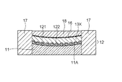
図1は、本実施形態における水中摺動部材の概略構成を示す外観図であり、図2は、本実施形態における水中摺動部材の概略構成を示す断面図である。
(First embodiment)
FIG. 1 is an external view showing a schematic configuration of an underwater sliding member in the present embodiment, and FIG. 2 is a cross-sectional view showing a schematic configuration of the underwater sliding member in the present embodiment.
図1及び図2に示すように、本実施形態の水中摺動部材(以下、「摺動部材」と略す場合がある)10は、第1の金属材料からなる基材11と、この基材11上に接合され、第2の金属材料からなる多孔質構造の中間層12と、少なくとも中間層12の多孔質構造の空孔内に一部が溶融して充填された腐食防止層122と、少なくとも腐食防止層122上に形成され、樹脂材料からなる摺動層13とを有している。
As shown in FIGS. 1 and 2, an underwater sliding member (hereinafter sometimes abbreviated as “sliding member”) 10 of the present embodiment includes a
この樹脂材料は、機械特性向上の観点からカーボン繊維等の導電性のある充填材を含有している。なお、図1において、参照符号15で示す部材は、摺動部材10が摺動する部材である軸を示し、これによって、本実施形態における摺動部材10は軸受として機能する。
This resin material contains a conductive filler such as carbon fiber from the viewpoint of improving mechanical properties. In FIG. 1, a member denoted by
中間層12は、第2の金属材料からなる複数の球状部材121が基材11の主面11A上に、この主面11Aと結合するようにして形成され、多孔質構造を構成している。なお、複数の球状部材121の基材11の主面11Aに対する結合は、例えば以下に説明するろう材を用いる方法(ろう付け接合法)あるいは固相拡散接合法によって行うことができる。球状部材121は、一部又は全部が繊維状部材であってもよい。
The
図1及び図2から明らかなように、複数の球状部材121によって構成される多孔質構造の第1の空孔121Aの形状は異方である。摺動層13の樹脂材料を第1の空孔121A中に充填させる場合、第1の空孔121Aの隅々まで充填するのは困難であり、第1の空孔121A内に樹脂材料が充填されない部分がすき間として残留する場合がある。
As apparent from FIGS. 1 and 2, the shape of the
腐食防止層122は、基材11の主面11A及び複数の球状部材121の表面を覆うように形成されている。腐食防止層122は、樹脂材料よりも融点が低い材料の場合は、第1の空孔121Aの摺動層13の樹脂材料が充填されない部分(すき間)に入り込み、すき間を充填する。
The
摺動層13は、腐食防止層122上に形成され、その一部が中間層12の第1の空孔121Aを腐食防止層122で被覆後の第2の空孔122A内に入り込み、第2の空孔122Aに充填される。
The
本実施形態の水中摺動部材は、基材11の主面11A及び複数の球状部材121の表面を覆うようにして腐食防止層122を形成するようにしているので、摺動層13の樹脂材料がカーボン繊維等の導電性のある充填材を含む場合であっても、水中環境において軸15から摺動部材10を通して軸受基材に流れる腐食電流を遮断することができ、軸の腐食を防止することができる。
Since the underwater sliding member of this embodiment forms the
また、水中環境において中間層12の多孔質構造の第1の空孔121A内に樹脂材料が充填されない部分(すき間)があると、すき間に水が入り込むようになって、すき間を起点として腐食が生じるようになる(すき間腐食)。
In addition, if there is a portion (a gap) in which the resin material is not filled in the
しかしながら、本実施形態においては、基材11の主面11A及び複数の球状部材121の表面を覆うようにして腐食防止層122を形成するようにしているので、上述のようなすき間を抑制することができ、これによってすき間腐食を抑制し、摺動部材10(軸受部材)を水中で長時間使用した場合においても、機械特性が経時的に劣化するのを抑制することができる。
However, in the present embodiment, since the
このように本実施形態によれば、摺動部材10を水中で長時間使用した場合においても、軸15から摺動部材10を通して軸受基材に流れる腐食電流を遮断することで軸の腐食を防止することができるとともに、長期に亘って高い機械特性を呈することができる。
Thus, according to the present embodiment, even when the sliding
基材11は耐食性及び機械特性に優れた、鉄及びクロムからなるステンレス鋼、鉄、クロム、及びニッケルからなるステンレス鋼、並びに鉄、クロム、ニッケル、モリブデン、マンガン、シリコン、ニオブ及びチタンからなるステンレス鋼から構成することができる。
The
中間層12を構成する球状部材121も同じく耐食性及び機械特性に優れた、鉄及びクロムからなるステンレス鋼、鉄、クロム、及びニッケルからなるステンレス鋼、並びに鉄、クロム、ニッケル、モリブデン、マンガン、シリコン、ニオブ及びチタンからなるステンレス鋼から構成することができる。
The
腐食防止層122は、電気的絶縁性を有していれば如何なる材料から構成してもよいが、以下に説明する製造方法に起因して融点の低いフッ素樹脂、特にはパーフルオロエチレン樹脂(融点300〜310℃)、テトラフルオロエチレン・ヘキサフルオロエチレン共重合体(融点260℃)から構成することが好ましい。なお、これらの樹脂及び共重合体には、必要に応じて樹脂系、セラミックス系、金属系の充填材、例えばウィスカーや繊維、粒子状の充填材を含有させることができる。
The
摺動層13は所定の樹脂材料から構成することができ、例えば四フッ化エチレン樹脂(融点327℃)、パーフルオロエチレン系樹脂(融点300〜310℃)、ヘキサフルオロプロピレン樹脂(融点260℃)、ポリエーテルエーテルケトン樹脂(融点334℃)、ポリフェニレンサルファイド樹脂(融点280℃)などを使用することができる。四フッ化エチレン樹脂などのフッ素系樹脂は摩擦係数が低いが、機械特性が若干低い。一方、ポリエーテルエーテルケトン樹脂などの樹脂は摩擦係数は高いが、機械特性も高い。したがって、摺動層13、すなわち摺動部材10に対して要求される特性を適宜考慮して、最適な材料を選択する必要がある。
The sliding
但し、本実施形態で示すように、摺動部材10を軸受部材として使用する場合において、摺動部材10の機械特性は基材11によってある程度担保されているので、摺動層13は主として摩擦係数が低く、摺動特性に優れることが好ましい。したがって、上述した材料の中でもフッ素系樹脂、特に四フッ化エチレン樹脂が好ましい。なお、これらの樹脂材料は、機械特性向上の観点からウィスカーや繊維、粒子等の充填材を含有させている。
However, as shown in the present embodiment, when the sliding
樹脂材料に含有させる充填材は、炭素及びグラファイトの少なくとも一方を含む繊維及び粒子からなる充填材、さらには、チタン酸カリウム、ホウ酸アルミニウム及び酸化亜鉛の少なくとも一種のウィスカー、繊維及び粒子からなる追加の充填材を含む。これらの充填材は、特に、摺動する相手部材がステンレス鋼等からなる場合において、相手部材を摩耗させたり、損傷させたりすることなく、高い耐摩耗性を有することができる。 The filler to be contained in the resin material is a filler composed of fibers and particles containing at least one of carbon and graphite, and additionally, at least one kind of whisker, fiber and particles of potassium titanate, aluminum borate and zinc oxide. Containing fillers. These fillers can have high wear resistance without causing wear or damage to the mating member, particularly when the sliding mating member is made of stainless steel or the like.
次に、本実施形態の摺動部材10の製造方法について説明する。図3〜図6は、摺動部材10の製造方法の一例を示す工程図である。なお、図3〜図6は、図2に示す摺動部材10の断面図に関連させて、摺動部材10の製造過程における各工程の状態を示したものである。
Next, the manufacturing method of the sliding
最初に、図3に示すように、金型17を準備し、この金型17内に基材11を配置し、基材11の主面11A上に図示しないろう材を塗布する。次いで、基材11の主面11A上に、複数の球状部材121を所定のピッチで配置するとともに、基材11及び球状部材121、並びにろう材を減圧雰囲気下、加熱してろう材を溶融させ、その後、冷却することによって、複数の球状部材121を基材11の主面11A上にろう材を介して結合する(ろう付け接合法)。
First, as shown in FIG. 3, a
なお、ろう材を用いる代わりに、固相拡散接合法により、複数の球状部材121を基材11の主面11Aに対して直接結合させることもできる。
Instead of using the brazing material, the plurality of
次いで、フッ素樹脂等の原料粉末をあらかじめ有機溶媒中に溶解あるいは分散させて溶液あるいは分散液を得、この溶液あるいは分散液に複数の球状部材121を結合した基材11を含浸させながら、この溶液あるいは分散液を基材11の主面11A及び複数の球状部材121の表面に塗布及び乾燥することによって、上記原料粉末を基材11の主面11A及び複数の球状部材121上に付着させる。その後、上記原料粉末を加熱して溶融処理させることによって腐食防止層122を形成する。
Next, a raw material powder such as fluororesin is dissolved or dispersed in advance in an organic solvent to obtain a solution or dispersion, and this solution or dispersion is impregnated with the
なお、原料粉末の加熱溶融処理は、以下に説明する摺動層13を形成する際の焼成の工程において同時に行うことができる。この場合、腐食防止層122を形成する場合の工程を別途設ける必要がないので、摺動部材10の製造工程を簡略化することができる。
In addition, the heat-melting process of raw material powder can be performed simultaneously in the baking process at the time of forming the sliding
次いで、図4に示すように、摺動層13の原料粉末である四フッ化エチレン樹脂等の原料粉末13Xを、複数の球状部材121を内包した腐食防止層122上に分散配置させるとともに、分散配置した原料粉末13X上に不織布16及び圧力伝達媒体18を配置する。なお、不織布16及び圧力伝達媒体18は、後に上パンチを用いて圧縮成型した際に、当該上パンチの離型性を向上させるためのものであり、このような観点から、圧力伝達媒体18としては、摩擦係数の低いフッ素系樹脂、特には四フッ化エチレン樹脂の粉末から構成することが好ましい。
Next, as shown in FIG. 4, the
なお、この工程において、原料粉末13Xの一部は腐食防止層122で被覆後の多孔質構造の第2の空孔122Aに充填されるようになる。
In this step, part of the
次いで、図5に示すように、不織布16及び圧力伝達媒体18を介し、上パンチ19を用いて原料粉末13Xを圧縮成型するとともに、所定の温度で加熱して原料粉末13Xを焼成させ、摺動層13を形成する。なお、上述したように、図5に示す工程において、原料粉末Xを焼成する際に併せて腐食防止層122の原料粉末を加熱溶融処理させ、当該腐食防止層122を形成することもできる。
Next, as shown in FIG. 5, the
上記加熱温度は、原料粉末13Xを四フッ化エチレン樹脂等の低融点のフッ素系樹脂から構成する場合は、400℃以下の温度に設定する。また、腐食防止層122を図5に示す工程において、その原料粉末を上述のようにパーフルオロエチレン樹脂等とし、上記同様に400℃以下の温度で加熱することにより、原料粉末13Xの焼成と同時に加熱溶着処理することができ、目的とする腐食防止層122を形成することができる。
The heating temperature is set to a temperature of 400 ° C. or lower when the
なお、この工程において、原料粉末13Xは中間層12の多孔質構造の第2の空孔122A内に十分に充填される。この際、空孔内にすき間が生じたとしても、上述のように、中間層12を構成する腐食防止層122によって、第1の空孔121Aのすき間が生じるような箇所には予め腐食防止層122が形成されて、当該すき間を埋設しているので、すき間腐食の原因となるすき間の生成を抑制することができる。
In this step, the
次いで、図6に示すように、上パンチ19を開放した後、不織布16及び圧力伝達媒体18を除去することによって、図1及び図2に示すような目的とする摺動部材10を得ることができる。
Next, as shown in FIG. 6, after the
上記例では、金型17内で基材11上に中間層12を形成したが、金型17外で、基材11上に中間層12を予め形成した後、図4に関連させて説明する、摺動層13を形成する段階で、基材11及び中間層12を含むアセンブリを金型17内に配置するようにすることもできる。
In the above example, the
なお、本実施形態の摺動部材10(軸受部材)は、例えば、水車、水車発電機、ポンプなどの水力機械における摺動部材(軸受部材)として好適に用いることができる。 In addition, the sliding member 10 (bearing member) of this embodiment can be used suitably as a sliding member (bearing member) in hydraulic machines, such as a water turbine, a water turbine generator, a pump, for example.
(第2の実施形態)
図7は、本実施形態における水中摺動部材の概略構成を示す断面図である。なお、本実施形態の水中摺動部材の外観図は、第1の実施形態における図1に示す形態と同様の構成を有する。
(Second Embodiment)
FIG. 7 is a cross-sectional view showing a schematic configuration of the underwater sliding member in the present embodiment. In addition, the external view of the underwater sliding member of this embodiment has the structure similar to the form shown in FIG. 1 in 1st Embodiment.
図7に示すように、本実施形態の水中摺動部材(以下、「摺動部材」と略す場合がある)20は、中間層22の構成が、図2に示す第1の実施形態における中間層12の構成と異なるのみで、その他の構成については同様であるので、本実施形態において、中間層22の構造を中心に説明する。なお、図1及び図2に示す構成要素と同一あるいは類似の構成要素については、同一の参照符号を用いている。
As shown in FIG. 7, the underwater sliding member 20 (hereinafter sometimes abbreviated as “sliding member”) 20 of the present embodiment has an
図7に示すように、本実施形態の摺動部材20は、第1の金属材料からなる基材11と、この基材11に接合され、第2の金属材料からなる多孔質構造の中間層22と、少なくとも中間層22の多孔質構造の空孔221A内に一部が溶融して充填された腐食防止層222と、少なくとも腐食防止層222上に形成され、樹脂材料からなる摺動層13とを有している。この樹脂材料は、機械特性向上の観点からカーボン繊維等の導電性のある充填材を含有している。なお、本実施形態における摺動部材20も、第1の実施形態における摺動部材10と同様に、軸受として機能させることができる。
As shown in FIG. 7, the sliding
中間層22は、第2の金属材料からなり、例えば、複数のパンチングプレートのパンチ穴の少なくとも一部が連通するように積層させて、その厚さ方向に沿った断面が、例えばT字型の複数の楔型部材221が基材11の主面11A上に、この主面11Aと結合するようにして形成され、多孔質構造を構成している。腐食防止層222は、基材11の主面11A及び複数の楔型部材221の表面を覆うように形成されている。
The
本実施形態の水中摺動部材は、基材11の主面11A及び複数の楔型部材221の表面を覆うようにして腐食防止層122を形成するようにしているので、摺動層13の樹脂材料がカーボン繊維等の導電性のある充填材を含む場合であっても、水中環境において軸15から摺動部材10を通して軸受基材に流れる腐食電流を遮断することができ、軸の腐食を防止することができる。
Since the underwater sliding member of this embodiment forms the
また、水中環境において中間層22の多孔質構造の第1の空孔221A内に樹脂材料が充填されない部分(すき間)があると、すき間に水が入り込むようになって、すき間を起点として腐食が生じるようになる(すき間腐食)。
In addition, if there is a portion (a gap) in which the resin material is not filled in the
しかしながら、本実施形態においては、基材11の主面11A及び複数の楔型部材221の表面を覆うようにして腐食防止層222を形成するようにしているので、上述のような第1のすき間を抑制することができ、これによってすき間腐食を抑制し、摺動部材20(軸受部材)を水中で長時間使用した場合においても、機械特性が経時的に劣化するのを抑制することができる。
However, in the present embodiment, since the
このように本実施形態によれば、摺動部材20を水中で長時間使用した場合においても、軸15から摺動部材20を通して軸受基材に流れる腐食電流を遮断することで軸の腐食を防止することができるとともに、長期に亘って高い機械特性を呈することができる。
As described above, according to this embodiment, even when the sliding
なお、その他の特徴、例えば、中間層22の楔型部材221の構成材料等は第1の実施形態における摺動部材10における球状部材121と同一であるので、説明を省略する。
Other features such as the constituent material of the wedge-shaped
本実施形態の摺動部材20の製造方法は、基本的には、中間層22の多孔質構造が複数の球状部材121で構成される代わりに、複数の楔型部材221で構成される点で異なり、その他の点については、図3〜図6に示すような工程を経て得ることができる。
The manufacturing method of the sliding
なお、複数の楔型部材221は、複数の球状部材121のように、予め断面形状がT字型の複数の楔型部材221を準備し、これらを複数の球状部材121の代わりに用いることもできる。一方、例えば大きさの異なる複数のパンチ穴が形成された2枚の板状部材を、当該パンチ穴が重複するようにして積層することによって、複数の楔型部材221とすることもできる。
As the plurality of wedge-shaped
図8及び図9は、パンチ穴が形成された2枚の板状部材を用いて複数の楔型部材221を形成する場合の一例を示す工程図である。
8 and 9 are process diagrams showing an example in which a plurality of wedge-shaped
図8に示すように、基板11の主面11A上に、パンチ穴221−2Aが形成された下板状部材221−2Xをろう付け等によって結合配置し、次いで、図9に示すように、パンチ穴221−1Aが形成された上板状部材221−2Xを、パンチ穴221−1Aとパンチ穴221−2Aとが一致するようにして、ろう付け等によって下板状部材221−1Xに対して結合配置する。この結果、図7に示すような楔型部材221を形成することができる。
As shown in FIG. 8, on the
なお、その他の腐食防止層122や摺動層13等を形成する工程は、図3〜図6に示す工程と同じであるので、説明を省略する。
In addition, since the process of forming the other
本実施形態の摺動部材20(軸受部材)は、例えば、水車、水車発電機、ポンプなどの水力機械における摺動部材(軸受部材)として好適に用いることができる。 The sliding member 20 (bearing member) of the present embodiment can be suitably used as a sliding member (bearing member) in a hydraulic machine such as a water wheel, a water turbine generator, or a pump.
上記第1の実施形態及び第2の実施形態においては、中間層12及び22の多孔質構造を構成する部材を球状及び楔型としたが、中間層12及び22の多孔質構造が摺動層13に対するアンカー効果を奏するという要件を満足すれば、上記部材の形状は特に限定されるものではない。例えば、中間層12及び22の多孔質構造の空孔は貫通していなくてもよい。
In the first embodiment and the second embodiment, the members constituting the porous structure of the
(実施例1)
まず、円筒形状を持つSUS316ステンレスからなる基材11の主面11AにAg−56質量%Cuろう材を塗布し、直径3mmのSUS316ステンレスからなる複数の鋼球121をその上に散布した後、1050℃、10−3Torrの真空中で加熱処理を行い、複数の鋼球121を基材11の主面11Aに結合させ、多孔質構造を形成した。
Example 1
First, an Ag-56 mass% Cu brazing material is applied to the
次いで、基材11の主面11A及び複数の鋼球121の表面に、テトラフルオロエチレン・ヘキサフルオロプロピレン共重合体の樹脂粉末を溶媒に分散してなる分散液を塗布し、乾燥させるという工程を、最終的な厚さが0.5mmとなるまで繰り返し、基材11の主面11A及び複数の鋼球121の表面に上記樹脂粉末を付着させた。
Next, a step of applying a dispersion liquid in which a resin powder of tetrafluoroethylene / hexafluoropropylene copolymer is dispersed in a solvent on the
次いで、基材11及び複数の鋼球121を内包し、腐食防止層122を含む中間層12からなるアセンブリを金型17内に配置し、このアセンブリ上に30質量%炭素繊維を含有した四フッ化エチレン樹脂の原料粉末を充填した。炭素繊維は、直径7〜10μm、長さ3mmの短繊維を用いた。
Next, an assembly composed of the
次いで、原料粉末上に厚さ0.3mmの不織布16及びPTFEからなる圧力伝達媒体(粉末)18を配置し、平面形状を有する成形パンチ19により、圧力50MPaで一方向に圧縮成形した。
Next, a
次いで、不織布16及び圧力伝達媒体18を除去した後、上記原料粉末の成型体を370℃、2時間加熱し、成型体を加熱溶融して摺動層13を形成するとともに、基材11の主面11A及び複数の鋼球121の表面に付着した樹脂粉末を加熱溶融して、当該表面に腐食防止層122を形成した。
Next, after removing the
このようにして得た摺動部材の腐食電流の流れ具合を調べたところ、腐食電流は遮断され、すき間腐食が生じないことを確認した。 When the corrosion current flow of the sliding member thus obtained was examined, it was confirmed that the corrosion current was cut off and no crevice corrosion occurred.
以上説明した少なくともひとつの実施形態によれば、水中環境において長時間使用した場合においても、機械特性が経時的に劣化するのを抑制することができる。 According to at least one embodiment described above, it is possible to suppress deterioration of mechanical characteristics over time even when used for a long time in an underwater environment.
以上、本発明のいくつかの実施形態を説明したが、これらの実施形態は例として掲示したものであり、発明の範囲を限定することは意図していない。これら新規な実施形態は、その他の様々な形態で実施されることが可能であり、発明の要旨を逸脱しない範囲で、種々の省略、置き換え、変更を行うことができる。これら実施形態やその変形は、発明の範囲や要旨に含まれるとともに、特許請求の範囲に記載された発明とその均等の範囲に含まれる。 As mentioned above, although several embodiment of this invention was described, these embodiment was posted as an example and is not intending limiting the range of invention. These novel embodiments can be implemented in various other forms, and various omissions, replacements, and changes can be made without departing from the scope of the invention. These embodiments and modifications thereof are included in the scope and gist of the invention, and are included in the invention described in the claims and the equivalents thereof.
10 水中摺動部材(軸受部材)
11 基材
11A 基材の主面
12、22 中間層
121 球状部材
122 腐食防止層
13 摺動層
15 軸
20 水中摺動部材(軸受部材)
221 楔型部材
10 Underwater sliding member (bearing member)
DESCRIPTION OF
221 wedge-shaped member
Claims (9)
第1の金属材料からなる基材と、
前記基材に接合され、第2の金属材料からなる多孔質構造の中間層と、
少なくとも前記中間層の多孔質構造の空孔内に一部が溶融して充填された腐食防止層と、
少なくとも前記腐食防止層上に形成され、四フッ化エチレン樹脂からなる母材と、前記母材より電気伝導度が高い炭素、グラファイト、チタン酸カリウム、ホウ酸アルミニウム及び酸化亜鉛の少なくとも一つの、繊維、ウィスカー及び粒子の少なくとも一つからなる充填材とを含む摺動層と、
を備えることを特徴とする水中摺動部材。 An underwater sliding member for use in water,
A base material made of a first metal material;
An intermediate layer of a porous structure joined to the substrate and made of a second metal material;
A corrosion preventing layer partially melted and filled in pores of the porous structure of the intermediate layer, and
A base material formed on at least the corrosion prevention layer and made of a tetrafluoroethylene resin, and at least one of carbon, graphite, potassium titanate, aluminum borate and zinc oxide having higher electrical conductivity than the base material. A sliding layer comprising a filler comprising at least one of whiskers and particles ,
An underwater sliding member comprising:
第1の金属材料からなる基材に第2の金属材料からなる多孔質構造の中間層を結合させる工程と、Bonding a porous intermediate layer made of a second metal material to a base material made of a first metal material;
少なくとも前記中間層の多孔質構造の空孔内に一部が溶融して充填された腐食防止層を形成する工程と、Forming a corrosion prevention layer that is at least partially melted and filled in the pores of the porous structure of the intermediate layer; and
少なくとも前記腐食防止層上に、四フッ化エチレン樹脂からなる母材と、前記母材より電気伝導度が高い炭素、グラファイト、チタン酸カリウム、ホウ酸アルミニウム及び酸化亜鉛の少なくとも一つの、繊維、ウィスカー及び粒子の少なくとも一つからなる充填材とを含む摺動層を形成する工程と、At least on the corrosion prevention layer, a base material made of tetrafluoroethylene resin, at least one of carbon, graphite, potassium titanate, aluminum borate, and zinc oxide having higher electrical conductivity than the base material, fibers, whiskers And forming a sliding layer comprising a filler consisting of at least one of particles,
を備えることを特徴とする水中摺動部材の製造方法。A method for producing an underwater sliding member.
Priority Applications (1)
| Application Number | Priority Date | Filing Date | Title |
|---|---|---|---|
| JP2012165761A JP5783966B2 (en) | 2011-08-08 | 2012-07-26 | Underwater sliding member, underwater sliding member manufacturing method, and hydraulic machine |
Applications Claiming Priority (3)
| Application Number | Priority Date | Filing Date | Title |
|---|---|---|---|
| JP2011173132 | 2011-08-08 | ||
| JP2011173132 | 2011-08-08 | ||
| JP2012165761A JP5783966B2 (en) | 2011-08-08 | 2012-07-26 | Underwater sliding member, underwater sliding member manufacturing method, and hydraulic machine |
Publications (2)
| Publication Number | Publication Date |
|---|---|
| JP2013052675A JP2013052675A (en) | 2013-03-21 |
| JP5783966B2 true JP5783966B2 (en) | 2015-09-24 |
Family
ID=47668122
Family Applications (1)
| Application Number | Title | Priority Date | Filing Date |
|---|---|---|---|
| JP2012165761A Active JP5783966B2 (en) | 2011-08-08 | 2012-07-26 | Underwater sliding member, underwater sliding member manufacturing method, and hydraulic machine |
Country Status (8)
| Country | Link |
|---|---|
| US (1) | US9404536B2 (en) |
| EP (1) | EP2743521B8 (en) |
| JP (1) | JP5783966B2 (en) |
| KR (1) | KR101536319B1 (en) |
| CN (1) | CN103717924B (en) |
| BR (1) | BR112014002858B1 (en) |
| CA (1) | CA2844238C (en) |
| WO (1) | WO2013021584A1 (en) |
Families Citing this family (9)
| Publication number | Priority date | Publication date | Assignee | Title |
|---|---|---|---|---|
| US20150192172A1 (en) * | 2011-05-17 | 2015-07-09 | Dresser-Rand Company | Coast down bushing for magnetic bearing systems |
| US9105561B2 (en) * | 2012-05-14 | 2015-08-11 | The Boeing Company | Layered bonded structures formed from reactive bonding of zinc metal and zinc peroxide |
| JP6193032B2 (en) * | 2013-07-18 | 2017-09-06 | 株式会社荏原製作所 | Sliding bearing device and pump equipped with the same |
| DE102014113971A1 (en) * | 2014-09-26 | 2016-03-31 | Thyssenkrupp Ag | Outboard device and method for coating an outboard device |
| PL3234386T3 (en) * | 2014-12-19 | 2019-11-29 | Saint Gobain Performance Plastics Pampus Gmbh | Sliding component and method of forming the same |
| US9835200B2 (en) * | 2015-04-15 | 2017-12-05 | Siemens Energy, Inc. | Generator bearing assembly and a method for lubricating a generator bearing assembly |
| EP3333437B1 (en) * | 2015-08-10 | 2021-03-03 | Dalian Sanhuan Composite Material Technology Development Co., Ltd. | Water lubricated composite thrust bearing of nuclear main pump |
| JP6885719B2 (en) * | 2016-12-27 | 2021-06-16 | 大豊工業株式会社 | Bush for sliding members and compressors |
| CN109989999A (en) * | 2017-12-29 | 2019-07-09 | 圣戈班性能塑料帕姆普斯有限公司 | Parts of bearings and its preparation and application |
Family Cites Families (20)
| Publication number | Priority date | Publication date | Assignee | Title |
|---|---|---|---|---|
| JPS59140298A (en) * | 1983-01-31 | 1984-08-11 | N D C Kk | Multi-layer bearing |
| JPS63314372A (en) * | 1987-06-15 | 1988-12-22 | Hitachi Ltd | Water-lubrication type bearing device for water wheel |
| DE69317605T2 (en) * | 1992-07-30 | 1998-08-20 | Oiles Industry Co Ltd | Multi-layer sliding part |
| DE69327377T2 (en) * | 1992-09-25 | 2000-06-08 | Oiles Industry Co Ltd | Multi-layer sliding part |
| JP3194866B2 (en) * | 1996-05-17 | 2001-08-06 | 株式会社東芝 | Composite material and method for producing the same |
| US6416846B2 (en) * | 1996-05-17 | 2002-07-09 | Kabushiki Kaisha Toshiba | Composite material and manufacturing method thereof |
| CN2313097Y (en) * | 1997-11-14 | 1999-04-07 | 何绍宗 | Water-lubricating axle sleeve |
| JPH11315294A (en) * | 1998-02-17 | 1999-11-16 | Oiles Ind Co Ltd | Oil-containing multilayered sliding member |
| JP2000055054A (en) * | 1998-08-11 | 2000-02-22 | Ntn Corp | Combined layer bearing |
| JP2000145785A (en) | 1998-11-10 | 2000-05-26 | Hitachi Ltd | Thrust bearing device |
| JP2001263340A (en) * | 2000-03-16 | 2001-09-26 | Hitachi Ltd | Method for manufacturing bearing |
| JP2002194380A (en) * | 2000-12-27 | 2002-07-10 | Daido Metal Co Ltd | Multilayer sliding member |
| JP2002225164A (en) * | 2001-02-05 | 2002-08-14 | Toshiba Corp | Slide material and method for manufacturing the same |
| JP4519355B2 (en) | 2001-04-25 | 2010-08-04 | オイレス工業株式会社 | Underwater sliding member and manufacturing method thereof |
| JP2003021144A (en) * | 2001-07-10 | 2003-01-24 | Toshiba Corp | Resin composite sliding member and manufacturing method of the same |
| JP2005036819A (en) * | 2003-07-15 | 2005-02-10 | Daido Metal Co Ltd | Multiple layered sliding member |
| DE60326780D1 (en) * | 2003-11-25 | 2009-04-30 | Oiles Industry Co Ltd | BUSH CAMP |
| JP2006063279A (en) * | 2004-08-30 | 2006-03-09 | Ntn Corp | In-liquid sliding material |
| CN100398855C (en) * | 2005-07-21 | 2008-07-02 | 重庆大学 | Circular arc groove water lubricating rubber alloy bearing |
| EP2696087B1 (en) | 2011-04-05 | 2017-01-18 | Kabushiki Kaisha Toshiba | Bearing device and hydraulic machine |
-
2012
- 2012-07-26 JP JP2012165761A patent/JP5783966B2/en active Active
- 2012-08-01 CA CA2844238A patent/CA2844238C/en active Active
- 2012-08-01 EP EP12821440.0A patent/EP2743521B8/en active Active
- 2012-08-01 BR BR112014002858-3A patent/BR112014002858B1/en not_active IP Right Cessation
- 2012-08-01 CN CN201280038534.2A patent/CN103717924B/en active Active
- 2012-08-01 KR KR1020147002408A patent/KR101536319B1/en active IP Right Grant
- 2012-08-01 WO PCT/JP2012/004884 patent/WO2013021584A1/en unknown
-
2014
- 2014-02-06 US US14/173,839 patent/US9404536B2/en active Active
Also Published As
| Publication number | Publication date |
|---|---|
| EP2743521A4 (en) | 2015-06-03 |
| BR112014002858A2 (en) | 2017-02-21 |
| EP2743521B8 (en) | 2018-10-31 |
| EP2743521B1 (en) | 2018-09-19 |
| CA2844238C (en) | 2017-04-25 |
| EP2743521A1 (en) | 2014-06-18 |
| KR101536319B1 (en) | 2015-07-13 |
| JP2013052675A (en) | 2013-03-21 |
| CN103717924A (en) | 2014-04-09 |
| US9404536B2 (en) | 2016-08-02 |
| CN103717924B (en) | 2016-08-17 |
| WO2013021584A1 (en) | 2013-02-14 |
| US20140153852A1 (en) | 2014-06-05 |
| CA2844238A1 (en) | 2013-02-14 |
| BR112014002858B1 (en) | 2021-05-25 |
| KR20140031988A (en) | 2014-03-13 |
Similar Documents
| Publication | Publication Date | Title |
|---|---|---|
| JP5783966B2 (en) | Underwater sliding member, underwater sliding member manufacturing method, and hydraulic machine | |
| JP5443734B2 (en) | Composite bearing member, method for manufacturing composite bearing member, bearing device, and rotating electrical machine | |
| CN101788015B (en) | Three-layer self lubricating abrasion-resistant slide bearing material and preparation method thereof | |
| JP5615293B2 (en) | Sliding element and method for manufacturing the same | |
| JP5318619B2 (en) | Sintered metal bearing | |
| US10584748B2 (en) | Plain bearing and method for producing the same | |
| WO2010106909A1 (en) | Sintered metallic bearing and fluid dynamic bearing device equipped with the bearing | |
| JP2015537173A (en) | High strength, low friction engineering materials for bearings and other applications | |
| KR20100125251A (en) | Sintered bearing | |
| JP2016500430A (en) | Thrust washer | |
| KR20160133237A (en) | Oilless bearing comprising sliding layer consisted of complex element | |
| JP6287721B2 (en) | Polymer electrolyte fuel cell and separator | |
| JP2015232382A (en) | Cage for rolling bearing and rolling bearing | |
| JP6377452B2 (en) | Composite, its manufacturing method, and composite bearing member | |
| JP2014152914A (en) | Resin bearing, manufacturing method of the same, and component member separation method of the same | |
| JP3794192B2 (en) | Thrust bearing manufacturing method | |
| JP2011058542A (en) | Sintered metallic bearing and fluid dynamic pressure bearing device equipped with the bearing | |
| JP2000145785A (en) | Thrust bearing device | |
| KR102048386B1 (en) | Composite bearing comprising solid lubrication layer and method for manufacturing the same | |
| JP7453894B2 (en) | Sliding member for vertical shaft rotating electrical machine and manufacturing method of sliding member for vertical shaft rotating electrical machine | |
| JP3852407B2 (en) | Liquid-containing molded porous body | |
| KR20200081332A (en) | Flexible lithium battery | |
| JP2018062580A (en) | Friction material and method for producing the same | |
| JP2015055329A (en) | Resin roller, and method of manufacturing the same |
Legal Events
| Date | Code | Title | Description |
|---|---|---|---|
| A621 | Written request for application examination |
Free format text: JAPANESE INTERMEDIATE CODE: A621 Effective date: 20140220 |
|
| A977 | Report on retrieval |
Free format text: JAPANESE INTERMEDIATE CODE: A971007 Effective date: 20141114 |
|
| A131 | Notification of reasons for refusal |
Free format text: JAPANESE INTERMEDIATE CODE: A131 Effective date: 20141125 |
|
| A521 | Request for written amendment filed |
Free format text: JAPANESE INTERMEDIATE CODE: A523 Effective date: 20150109 |
|
| TRDD | Decision of grant or rejection written | ||
| A01 | Written decision to grant a patent or to grant a registration (utility model) |
Free format text: JAPANESE INTERMEDIATE CODE: A01 Effective date: 20150623 |
|
| A61 | First payment of annual fees (during grant procedure) |
Free format text: JAPANESE INTERMEDIATE CODE: A61 Effective date: 20150721 |
|
| R150 | Certificate of patent or registration of utility model |
Ref document number: 5783966 Country of ref document: JP Free format text: JAPANESE INTERMEDIATE CODE: R150 |
|
| S111 | Request for change of ownership or part of ownership |
Free format text: JAPANESE INTERMEDIATE CODE: R313115 |
|
| R350 | Written notification of registration of transfer |
Free format text: JAPANESE INTERMEDIATE CODE: R350 |
|
| S111 | Request for change of ownership or part of ownership |
Free format text: JAPANESE INTERMEDIATE CODE: R313115 Free format text: JAPANESE INTERMEDIATE CODE: R313114 |
|
| R350 | Written notification of registration of transfer |
Free format text: JAPANESE INTERMEDIATE CODE: R350 |
|
| R350 | Written notification of registration of transfer |
Free format text: JAPANESE INTERMEDIATE CODE: R350 |