JP5779985B2 - Laminate for authenticity judgment - Google Patents
Laminate for authenticity judgment Download PDFInfo
- Publication number
- JP5779985B2 JP5779985B2 JP2011117857A JP2011117857A JP5779985B2 JP 5779985 B2 JP5779985 B2 JP 5779985B2 JP 2011117857 A JP2011117857 A JP 2011117857A JP 2011117857 A JP2011117857 A JP 2011117857A JP 5779985 B2 JP5779985 B2 JP 5779985B2
- Authority
- JP
- Japan
- Prior art keywords
- layer
- laminate
- concavo
- phase difference
- polarizer
- Prior art date
- Legal status (The legal status is an assumption and is not a legal conclusion. Google has not performed a legal analysis and makes no representation as to the accuracy of the status listed.)
- Active
Links
Images

Landscapes
- Credit Cards Or The Like (AREA)
- Polarising Elements (AREA)
- Inspection Of Paper Currency And Valuable Securities (AREA)
Description
本発明は、例えば、偽造防止効果、装飾効果及び/又は美的効果を提供する表示技術に関する。 The present invention relates to a display technology that provides, for example, an anti-counterfeit effect, a decorative effect, and / or an aesthetic effect.
クレジットカード及び紙幣などの物品には、その偽造を防止することなどを目的として、特殊な視覚効果を有した光学素子が貼り付けられている。また、同様の目的で、物品を包装する包装体に光学素子を貼り付けることがある。さらに、装飾効果や美的効果を狙って、このような光学素子が物品に貼り付けられることがある。 Optical elements having a special visual effect are attached to articles such as credit cards and banknotes for the purpose of preventing counterfeiting. For the same purpose, an optical element may be attached to a package for packaging an article. Furthermore, such an optical element may be affixed to an article for a decorative effect or an aesthetic effect.
このような例として、特許文献1または2に記載される光学素子が存在する。これらの光学素子では、互いに異なる偏光を生じさせる2つの偏光子が潜像を形成している。これらの潜像は、別の偏光子を介して観察したときに高コントラスト比の像として視認可能となる。しかしながら、これらの光学素子では直線偏光が利用されており、最適な表示のためには、検証器としての偏光フィルムを光学素子に対して一定の角度に維持する必要があり、操作が煩雑となる。特に、光学素子を例えばステッカーとして物品の立体的な部位に貼り付ける場合、検証器に対する角度が部位によって異なるため、像全体を高いコントラストで表示させることは困難となる。
As such an example, there is an optical element described in
一方、特許文献3には、視認可能な観察角度の範囲を広くすることを課題する、円偏光子を利用した光学素子が記載されている。しかし、この光学素子では、複屈折性層を遅相軸が互いに異なる2つの部分に作りわける必要があるため、効率良く生産することが困難である。 On the other hand, Patent Document 3 describes an optical element using a circular polarizer, which has a problem of widening the range of viewing angles that can be visually recognized. However, in this optical element, it is difficult to produce the birefringent layer efficiently in two parts having different slow axes.
本発明は、クレジットカード及び紙幣などの物品の偽造防止において、より高精度でセキュリティー性の高い、光学素子を有する真贋判定用の積層体を提供することを目的とする。 An object of the present invention is to provide a layered body for authenticity determination having an optical element with higher accuracy and higher security in preventing forgery of articles such as credit cards and banknotes.
本発明は上記課題を解決する為のものであり、本発明の請求項1に係る発明は、線状の凹凸構造が形成された偏光層を背面に、λ/4の位相差値を有する位相差層を表示面に配する真贋判定用の積層体であって、前記偏光層が深さ100〜500nm、中心線間距離150nm以上の凹凸構造を有し、該凹凸構造が前記位相差層の位相差光軸に対して±45°に位置するように配置して円偏光子機能を付与したパターンと、且つ、前記凹凸構造を位相差光軸に対して、0°および90°に位置するように配置して直線偏光子機能を付与したパターンとからなることを特徴とする真贋判定用の積層体である。
The present invention has been made to solve the above problems, the invention according to
また、本発明の請求項2に係る発明は、前記凹凸構造の表面に金属薄膜からなる反射層を設けることを特徴とする請求項1に記載の真贋判定用の積層体である。
The invention according to
また、本発明の請求項3に係る発明は、前記位相差層が、液晶または樹脂フィルムからなることを特徴とする請求項1または2に記載の真贋判定用の積層体である。
The invention according to claim 3 of the present invention is the laminate for authenticity determination according to
本発明により、クレジットカード及び紙幣などの物品の偽造防止において、より高精度でセキュリティー性の高い、光学素子を有する真贋判定用の積層体を提供することができる。 According to the present invention, it is possible to provide a layered body for authenticity determination having an optical element with higher accuracy and higher security in preventing forgery of articles such as credit cards and banknotes.
以下、本発明の態様について、図面を参照しながら詳細に説明する。なお、全ての図面を通じて同様又は類似した機能を発揮する構成要素には同一の参照符号を付し、重複する説明は省略する。 Hereinafter, embodiments of the present invention will be described in detail with reference to the drawings. In addition, the same referential mark is attached | subjected to the component which exhibits the same or similar function through all the drawings, and the overlapping description is abbreviate | omitted.
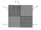
図1は、本発明の積層体の一実施形態を示す基本的な偏光子の平面概略図である。前記回折構造を位相差光軸に対して、90°に位置するように配置した直線偏光子(1)と0°に位置するように配置した直線偏光子(1´)の異なる2種の直線偏光子機能と、前記回折構造を位相差光軸に対して、−45°に位置するように配置した円偏光子(2)と+45°に位置するように配置した円偏光子(2´)の異なる2種の円偏光子機能からなる基本的な偏光子を示す。 FIG. 1 is a schematic plan view of a basic polarizer showing an embodiment of a laminate of the present invention. Two different straight lines, the linear polarizer (1) arranged so that the diffractive structure is located at 90 ° with respect to the phase difference optical axis and the linear polarizer (1 ′) arranged so as to be located at 0 ° Polarizer function, a circular polarizer (2 ′) arranged so that the diffraction structure is located at −45 ° with respect to the phase difference optical axis, and a circular polarizer (2 ′) arranged so as to be located at + 45 ° The basic polarizer which consists of two types of circular polarizer functions from which these are different is shown.
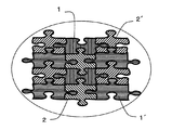
図2は、本発明の積層体の一実施形態を示す偏光子の平面概略図である。図1に示す基本的な4つの異なる偏光子を組み合わせて様々なデザインを潜像として作成することができる。具体的な用途としては、様々なデザインを潜像として作成した積層体を、高度なセキュリティ性が要求されるパスポート、商品券やBPステッカーとして真贋判定に利用できる。 FIG. 2 is a schematic plan view of a polarizer showing an embodiment of the laminate of the present invention. Various basic polarizers shown in FIG. 1 can be combined to create various designs as latent images. As a specific application, a laminate in which various designs are created as latent images can be used for authenticity determination as a passport, gift certificate or BP sticker that requires high security.
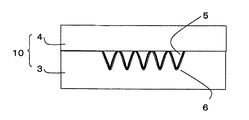
図3は、本発明の積層体の一実施形態を示す断面概略図である。具体的には偏光層(3)上に基本的な偏光子の組み合わせで凹凸形状(6)を形成し、その上に金属などの薄膜を施して反射層(5)を設け、さらにその上に位相差層(4)を設けて積層体(10)を得る。 FIG. 3 is a schematic cross-sectional view showing an embodiment of the laminate of the present invention. Specifically, the concave / convex shape (6) is formed on the polarizing layer (3) by a combination of basic polarizers, and a reflective layer (5) is provided thereon by applying a thin film of metal or the like thereon. A retardation layer (4) is provided to obtain a laminate (10).
図4は、偏光層(3)上に図1に示す基本的な偏光子の組み合わせで凹凸構造(6)を形成した、本発明の積層体の一実施形態を示す平面概略図である。 FIG. 4 is a schematic plan view showing an embodiment of the laminate of the present invention in which the concavo-convex structure (6) is formed on the polarizing layer (3) by the combination of the basic polarizers shown in FIG.
<積層体>
本発明に係る積層体(10)は図3に示すように、偏光層(3)およびそれに向かい合った)位相差層(4)を含んでいる。積層体(10)の前面、すなわち表示面は位相差層(4)側の面であり、積層体(10)の背面は偏光層(3)である。
<Laminate>
As shown in FIG. 3, the laminate (10) according to the present invention includes a polarizing layer (3) and a retardation layer (4) facing the polarizing layer (3). The front surface of the laminate (10), that is, the display surface is the surface on the phase difference layer (4) side, and the back surface of the laminate (10) is the polarizing layer (3).
<偏光層>
本発明に係る偏光層は、線状の凹凸構造が形成された樹脂層と、該凹凸構造をアルミニウムなどの金属やアルミニウム合金などの合金からなる金属薄膜で覆う反射層(5)から構成される。
<Polarizing layer>
The polarizing layer according to the present invention includes a resin layer in which a linear concavo-convex structure is formed, and a reflective layer (5) that covers the concavo-convex structure with a metal thin film made of a metal such as aluminum or an alloy such as an aluminum alloy. .
前記樹脂層は、線状の凹凸構造(6)が形成できるものであれば特に限定されない。例えば、汎用の熱可塑性樹脂や紫外線硬化型樹脂などが使用できる。 The resin layer is not particularly limited as long as the linear uneven structure (6) can be formed. For example, a general-purpose thermoplastic resin or ultraviolet curable resin can be used.
前記、線状の凹凸構造(6)は偏光機能を有するように設計されていてる。ここにいう偏光分離機能とは、端的には、自然光として可視域内の少なくとも一部の波長範囲内の光を照射したときに、反射光として直線偏光または自然光に直線偏光が混ざってなる部分偏光を射光する機能である。特に凹凸構造の溝の長さ方向に依存した偏光分離機能を示し、より効果的な偏光分離機能を引き出す為には、前記凹凸構造の溝の深さ100〜500nm、中心線間距離150nm以上が好ましい。 The linear concavo-convex structure (6) is designed to have a polarization function. In short, the polarization separation function referred to here is a linearly polarized light as a reflected light or a partially polarized light that is mixed with a linearly polarized light as a reflected light when irradiated with light in at least a part of the visible wavelength range as natural light. It is a function to shine. In particular, in order to exhibit a polarization separation function depending on the length direction of the groove of the concavo-convex structure, and to extract a more effective polarization separation function, the groove depth of the concavo-convex structure is 100 to 500 nm, and the distance between the center lines is 150 nm or more. preferable.
上記偏光層の線状の凹凸構造を形成方法としては、凹凸構造(6)が形成できる方法であれば限定するものではない。例えば、下記の位相差層上に、前記樹脂を塗布し、凹凸構造(6)を別途作製の偏光子形成用エンボス版にてエンボス形成し、その後、前記凹凸構造(6)を金属薄膜で覆うように反射層(5)を形成して作製することができる。あるいは別途、前記樹脂層に凹凸構造(6)を形成し、その裏面に接着層を設けた転写箔を作製し、位相差層(4)に転写して偏光層(3)を作製することも出来る。 The method for forming the linear uneven structure of the polarizing layer is not limited as long as the uneven structure (6) can be formed. For example, the resin is applied onto the following retardation layer, and the concavo-convex structure (6) is embossed with a separately prepared emboss plate for forming a polarizer, and then the concavo-convex structure (6) is covered with a metal thin film. Thus, the reflective layer (5) can be formed and produced. Alternatively, a polarizing foil (3) may be prepared by forming a concavo-convex structure (6) on the resin layer, producing a transfer foil having an adhesive layer on the back surface, and transferring it to the retardation layer (4). I can do it.
また、前記反射層(5)は、凹凸構造の偏光分離効果を向上させるためのものであり、アルミニウムなどの金属やアルミニウム合金などの合金からなる金属材料の薄膜層からなる。前記薄膜層は、蒸着法やスパッタ法などの気相薄膜形成方法などにより形成することができる。 The reflective layer (5) is for improving the polarization separation effect of the concavo-convex structure, and comprises a thin film layer of a metal material made of a metal such as aluminum or an alloy such as an aluminum alloy. The thin film layer can be formed by a vapor phase thin film forming method such as an evaporation method or a sputtering method.
<位相差層>
本発明に係る位相差層(4)は、液晶もしくは樹脂フィルムを用いることができ、複屈折性の層であり、その主面に平行な光学軸を有している。
<Phase difference layer>
The retardation layer (4) according to the present invention can be a liquid crystal or a resin film, is a birefringent layer, and has an optical axis parallel to the principal surface.
本発明の真贋判定用の積層体(10)は、例えば、表示面である位相差層(4)が有する光学軸に対して、背面の偏光層(3)の線状の凹凸構造をいろいろな角度で配置することにより、様々な角度の偏光機能を付与することができ、その結果、様々な潜像をデザインすることができる。 The laminated body (10) for authenticity determination of the present invention has various linear concavo-convex structures of the back polarizing layer (3) with respect to the optical axis of the retardation layer (4) as the display surface, for example. By arranging at an angle, polarization functions at various angles can be provided, and as a result, various latent images can be designed.
例えば液晶の場合、△n=0.1の複屈折を有する液晶は、膜厚1.4μmでおよそλ/4の位相差を持つことが知られている。前記液晶を、配向処理したフィルムまたは延伸フィルムの分子配向に沿って並べることで位相差層(4)を得ることができる。なお、延伸フィルムは樹脂フィルムを一軸延伸することにより得られる。樹脂フィルムを一軸延伸すると、樹脂の構成分子またはその官能基が延伸方向に配向し、その結果、樹脂フィルムに複屈折性が生じる。 For example, in the case of a liquid crystal, it is known that a liquid crystal having a birefringence of Δn = 0.1 has a phase difference of approximately λ / 4 with a film thickness of 1.4 μm. A phase difference layer (4) can be obtained by aligning the liquid crystals along the molecular orientation of the oriented film or stretched film. The stretched film can be obtained by uniaxially stretching a resin film. When the resin film is uniaxially stretched, the constituent molecules of the resin or their functional groups are oriented in the stretching direction, resulting in birefringence in the resin film.
また、例えばセロファンフィルムやポリカーボネートフィルムなどの市販の位相差フィルムを使用することもできる。 Moreover, commercially available retardation films, such as a cellophane film and a polycarbonate film, can also be used, for example.
以下、位相差層(4)の作用について、ここではλ/4の位相差値を有する位相差層を例により具体的に説明する。 Hereinafter, the operation of the retardation layer (4) will be described in detail by way of an example of a retardation layer having a retardation value of λ / 4.
位相差層(4)は、波長がλの自然光を入射させたときに、電界ベクトルの振動方向が遅相軸に対して平行な直線偏光を、電界ベクトルの振動方向が遅相軸に対して垂直な直線偏光に対してλ/4だけ遅延させて透過させる。このため、位相差層(4)に直線偏光を透過させると、その偏光面が遅相軸に対して斜めである場合、位相差層(4)は、透過光として円偏光または楕円偏光を射出する。なお、ここでは、ある直線偏光の「偏光面」は、その直線偏光の進行方向と電界ベクトルの振動方向とに対して平行な平面であるとする。 The phase difference layer (4) is a linearly polarized light whose electric field vector oscillation direction is parallel to the slow axis when natural light having a wavelength of λ is incident, and the electric field vector oscillation direction is relative to the slow axis. Transmission is performed with a delay of λ / 4 with respect to vertical linearly polarized light. For this reason, when linearly polarized light is transmitted through the retardation layer (4), when the plane of polarization is oblique with respect to the slow axis, the retardation layer (4) emits circularly or elliptically polarized light as transmitted light. To do. Here, it is assumed that the “polarization plane” of a certain linearly polarized light is a plane parallel to the traveling direction of the linearly polarized light and the vibration direction of the electric field vector.
例えば、上記の位相差層(4)の位相差光軸に対して、90°に位置するように配置した直線偏光子(1)と0°に位置するように配置した直線偏光子(1´)の異なる2種の直線偏光子機能と、前記回折構造を位相差光軸に対して、−45°に位置するように配置した円偏光子(2)と+45°に位置するように配置した円偏光子(2´)の異なる2種の円偏光機能からなる基本的な偏光子を、デザインに応じて前記偏光層に設けることができる。 For example, a linear polarizer (1) disposed at 90 ° and a linear polarizer (1 ′ disposed at 0 ° with respect to the phase difference optical axis of the retardation layer (4). ) And two types of linear polarizer functions, and the diffraction structure is arranged to be located at + 45 ° with the circular polarizer (2) arranged to be located at −45 ° with respect to the phase difference optical axis. Basic polarizers composed of two types of circular polarization functions having different circular polarizers (2 ′) can be provided in the polarizing layer according to the design.
上記の積層体の前面を白色光で照明し、その反射光を、円偏光子を介して観察した場合、例えば、一方の円偏光子(2)が明るく見え、且つ他方の円偏光子(2´)が暗く見えるか、または、一方の円偏光子(2)が暗く見え、且つ他方の円偏光子(2´)が明るく見える。すなわち、円偏光子を用いることで潜像を可視化することができ、セキュリティー性の高い真贋判定用の積層体を得ることができる。 When the front surface of the laminate is illuminated with white light and the reflected light is observed through a circular polarizer, for example, one circular polarizer (2) looks bright and the other circular polarizer (2 ′) Appears dark or one circular polarizer (2) appears dark and the other circular polarizer (2 ′) appears bright. That is, by using a circular polarizer, a latent image can be visualized, and a highly secure laminated body for authenticity determination can be obtained.
<用途>
本発明の積層体(10)は、紙幣、商品券、パスポートなどの真贋判定に利用する表示体として使用することができる。例えば、真正品としての物品に前記積層体をラベルとして、あるいは転写箔として転写法により貼り付け、検証具である円偏光子を介して観察し、潜像の可視化と所定の像を視認できれば真正品として判断し、視認できなければ偽造品と判断することができる。
<Application>
The laminated body (10) of this invention can be used as a display body utilized for authenticity determination, such as a banknote, a gift certificate, and a passport. For example, if the laminate is affixed to a genuine article as a label or a transfer foil by a transfer method and observed through a circular polarizer as a verification tool, the latent image can be visualized and a predetermined image can be visually confirmed. If it is judged as a product and is not visible, it can be judged as a counterfeit product.
以下に実施例により本発明を具体的に説明する。 The present invention will be specifically described below with reference to examples.
<実施例1>
[偏光子形成用エンボス版の作製]
ガラス基板に膜厚0.6μmのポジレジストを塗布し、そのポジレジスト面に電子線描画機を用いて方向の異なる(用いる位相差層の位相差光軸に対して、0°、90°、45°、−45°)線状の凹凸構造を形成し、その後現像して、深さ400nm、中心線間300nmの凹凸構造からなる、異なる偏光子が形成されたガラス原版を作製した。
<Example 1>
[Preparation of emboss plate for polarizer formation]
A positive resist with a film thickness of 0.6 μm is applied to a glass substrate, and the direction of the positive resist is different using an electron beam drawing machine (0 °, 90 ° with respect to the phase difference optical axis of the phase difference layer used) (45 °, −45 °) linear concavo-convex structure was formed and then developed to produce a glass original plate having a different polarizer having a concavo-convex structure with a depth of 400 nm and a center line of 300 nm.
次に、上記凹凸構造が形成された側のガラス原版上に、スパッタリング法により導電性薄膜(Ni)を設け、その後、Niのメッキを施して、前記ガラス基板と剥離して複版を作製しエンボス版を得た。 Next, a conductive thin film (Ni) is provided by sputtering on the glass original plate on the side where the concavo-convex structure is formed, and then Ni plating is applied to separate the glass substrate to produce a duplicate plate. I got an embossed version.
[偏光子の作製]
次に、以下の手順で偏光子を有する転写箔を作製した。
厚さ19μmのポリエステルフィルム(東レ社製、商品名「ルミラー19528」)の一方の面上に、アクリル系剥離剤(PMMA)を、乾燥後の膜厚が2μmになるようにグラビアコーティング法により塗布して剥離層を設けた。その後、前記剥離層上にUV硬化型樹脂(和信化学工業社製、「ポリスター200」)を膜厚2μmで塗布し、その塗布面に前記エンボス版を押し付け、前記ポリエステルフィルムの他方の面側から200mJ/cm2の紫外線を照射して硬化した。その後、前記ポリエステルフィルムとエンボス版を
剥がして、前記ポリエステルフィルム面に異なる凹凸構造からなる格子偏光子を形成した。
[Production of polarizer]
Next, the transfer foil which has a polarizer was produced in the following procedures.
On one side of a 19 μm thick polyester film (trade name “Lumirror 19528” manufactured by Toray Industries, Inc.), an acrylic release agent (PMMA) is applied by a gravure coating method so that the film thickness after drying becomes 2 μm. Then, a release layer was provided. Thereafter, a UV curable resin (manufactured by Washin Chemical Industry Co., Ltd., “Polystar 200”) is applied with a film thickness of 2 μm on the release layer, and the embossed plate is pressed against the coated surface, from the other surface side of the polyester film. It hardened | cured by irradiating a 200mJ / cm < 2 > ultraviolet-ray. Thereafter, the polyester film and the embossed plate were peeled off to form a lattice polarizer having a different uneven structure on the polyester film surface.
次に、上記ポリエステルフィルム全面に膜厚50nmのAl蒸着薄膜を形成し、その上に塩酢ビ系のマスクインク(東洋インキ社製、「LPVMS OPワニス」)を用いて、上記凹凸構造表面に同調させて印刷して、その後アルカリエッチングにより凹凸構造表面以外のAl蒸着薄膜を削除し、前記マスクインクを残したままで、Al薄膜を反射層とする凹凸構造を有する偏光子を形成した。
[転写箔の作製]
上記偏光子を形成した側のポリエステルフィルムの全面に、シリカフィラーを分散させた塩化ビニル−酢酸ビニル共重合体からなる接着剤(和信化学工業社製、「プラスコート
UA−1」)を用いて、厚さ2μmの接着層を形成し、偏光子の転写箔を作製した。
Next, an Al vapor-deposited thin film having a film thickness of 50 nm is formed on the entire surface of the polyester film, and a vinyl chloride-based mask ink (“LPVMS OP Varnish” manufactured by Toyo Ink Co., Ltd.) is used on the Al film. Printing was performed in synchronization, and then the Al deposited thin film other than the surface of the concavo-convex structure was deleted by alkali etching, and a polarizer having a concavo-convex structure using the Al thin film as a reflective layer was formed while leaving the mask ink.
[Production of transfer foil]
Using an adhesive made of a vinyl chloride-vinyl acetate copolymer in which a silica filler is dispersed (“Washin Chemical Industry Co., Ltd.,“ Plus Coat UA-1 ”) on the entire surface of the polyester film on the side where the polarizer is formed. Then, an adhesive layer having a thickness of 2 μm was formed to produce a polarizer transfer foil.
[積層体の作製]
次に、膜厚21μmの一軸延伸セロハンフィルムをλ/4の位相差値を有する位相差層として用い、この一軸延伸セロハンフィルムと上記偏光子の転写箔の接着層側と重ね、表面温度200℃のゴムロールにて加圧し、冷却後、前記転写箔の支持体であるポリエステルフィルムから剥離して真贋判定用の積層体を得た。
[Production of laminate]
Next, a uniaxially stretched cellophane film having a thickness of 21 μm is used as a retardation layer having a retardation value of λ / 4, and this uniaxially stretched cellophane film and the adhesive layer side of the transfer foil of the polarizer are overlapped, and the surface temperature is 200 ° C. After being pressed with a rubber roll and cooled, the laminate was peeled off from the polyester film as a support for the transfer foil to obtain a laminate for authenticity determination.
<実施例2>
実施例1と同様にして偏光子形成用エンボス版を作製した。
<Example 2>
An embossing plate for forming a polarizer was produced in the same manner as in Example 1.
次に、膜厚21μmの一軸延伸セロハンフィルムをλ/4の位相差値を有する位相差層として用い、一方の面にUV硬化型樹脂(和信化学工業社製、「ポリスター 200」)を膜厚2μmで塗布し、その塗布面に前記ポリエステルフィルムを支持体とするエンボス版を押し付け、前記セロハンフィルムの他方の面側から下記条件の紫外線を照射して硬化した。その後、前記エンボス版を剥がして真贋判定用の積層体を得た。 Next, a uniaxially stretched cellophane film having a film thickness of 21 μm is used as a retardation layer having a retardation value of λ / 4, and a UV curable resin (“Polystar 200” manufactured by Washin Chemical Industry Co., Ltd.) is formed on one surface. The embossed plate having the polyester film as a support was pressed against the coated surface, and cured by irradiating ultraviolet rays under the following conditions from the other surface side of the cellophane film. Thereafter, the embossed plate was peeled off to obtain a laminate for authenticity determination.
<実施例3>
下記の位相差層以外は実施例2と同様にして真贋判定用の積層体を得た。
膜厚15μmの一軸延伸フィルム(ユニチカ社製、「NC−15RT」)の一方の面に、△n=0.1の複屈折を有する液晶(BASF社製、「Lumogen S250」)を、膜厚1.4μmで塗布し、その後硬化させてλ/4の位相差値を有する位相差層を作製した。
<Example 3>
A laminated body for authenticity determination was obtained in the same manner as in Example 2 except for the retardation layer described below.
A liquid crystal having a birefringence of Δn = 0.1 (manufactured by BASF, “Lumogen S250”) is applied to one surface of a uniaxially stretched film (manufactured by Unitika, “NC-15RT”) having a film thickness of 15 μm. A retardation layer having a retardation value of λ / 4 was prepared by coating at 1.4 μm and then curing.
[積層体の検証]
実施例1〜3で得られた本発明品を、円偏光フィルムを介して視認したところ潜像が見えた。また、前記円偏光フィルムと異なる方向の円偏光フィルムを介して視認したところ、前記潜像とは異なる潜像が見えた。
[Verification of laminate]
When the product of the present invention obtained in Examples 1 to 3 was viewed through a circularly polarizing film, a latent image was seen. Moreover, when it visually recognized through the circularly-polarizing film of the direction different from the said circularly-polarizing film, the latent image different from the said latent image was seen.
1 90°の直線偏光、
1´ 0°の直線偏光
2 −45°の円偏光
2´ +45°の円偏光
3 偏光層
4 位相差層
5 反射層
6 凹凸構造
10 積層体
1 90 ° linearly polarized light,
1 '0 ° linearly polarized light 2-45 ° circularly polarized light 2' + 45 ° circularly polarized light 3 Polarizing layer 4
Claims (3)
The retardation layer laminate for authenticity determination according to claim 1 or 2, characterized in that a liquid crystal or a resin film.
Priority Applications (1)
| Application Number | Priority Date | Filing Date | Title |
|---|---|---|---|
| JP2011117857A JP5779985B2 (en) | 2011-05-26 | 2011-05-26 | Laminate for authenticity judgment |
Applications Claiming Priority (1)
| Application Number | Priority Date | Filing Date | Title |
|---|---|---|---|
| JP2011117857A JP5779985B2 (en) | 2011-05-26 | 2011-05-26 | Laminate for authenticity judgment |
Publications (2)
| Publication Number | Publication Date |
|---|---|
| JP2012247538A JP2012247538A (en) | 2012-12-13 |
| JP5779985B2 true JP5779985B2 (en) | 2015-09-16 |
Family
ID=47468039
Family Applications (1)
| Application Number | Title | Priority Date | Filing Date |
|---|---|---|---|
| JP2011117857A Active JP5779985B2 (en) | 2011-05-26 | 2011-05-26 | Laminate for authenticity judgment |
Country Status (1)
| Country | Link |
|---|---|
| JP (1) | JP5779985B2 (en) |
Family Cites Families (5)
| Publication number | Priority date | Publication date | Assignee | Title |
|---|---|---|---|---|
| EP0980536B1 (en) * | 1997-05-09 | 2004-05-26 | Rolic AG | Optical element |
| JP2004077954A (en) * | 2002-08-21 | 2004-03-11 | Dainippon Printing Co Ltd | Medium and method for confirming authenticity |
| JP4967298B2 (en) * | 2005-10-06 | 2012-07-04 | 凸版印刷株式会社 | Sticker with verification function, authenticity determination medium, thread body and authenticity determination paper |
| JP4983504B2 (en) * | 2007-09-21 | 2012-07-25 | 凸版印刷株式会社 | Information recording medium and information reading apparatus |
| JP5659786B2 (en) * | 2010-12-27 | 2015-01-28 | 凸版印刷株式会社 | Laminated body and method for producing the same |
-
2011
- 2011-05-26 JP JP2011117857A patent/JP5779985B2/en active Active
Also Published As
| Publication number | Publication date |
|---|---|
| JP2012247538A (en) | 2012-12-13 |
Similar Documents
| Publication | Publication Date | Title |
|---|---|---|
| AU2016201176B2 (en) | Forgery-proof medium and verification method | |
| JP4967298B2 (en) | Sticker with verification function, authenticity determination medium, thread body and authenticity determination paper | |
| JP2008309898A (en) | Forgery-prevented medium and discrimination method | |
| JP5381023B2 (en) | Image forming body | |
| JP5365292B2 (en) | Latent image forming body, authenticity determination method thereof, and medium using the same | |
| JP4670470B2 (en) | Hidden image laminate and method for producing the same | |
| US10647147B2 (en) | Anti-counterfeiting medium | |
| JP2013109129A (en) | Display body for forgery prevention, affixation label thereof, transfer foil and authenticity determination method | |
| JP2012159771A (en) | Forgery prevention medium and production method of the same, and method for determining authenticity of forgery prevention medium | |
| JP5779985B2 (en) | Laminate for authenticity judgment | |
| JP5310984B2 (en) | Anti-counterfeit medium having flexibility and its verification method | |
| JP5659786B2 (en) | Laminated body and method for producing the same | |
| JP5012681B2 (en) | Laminated body and method for producing the same | |
| JP5310983B2 (en) | Anti-counterfeit medium having flexibility and its verification method | |
| JP2013127593A (en) | Forgery prevention medium and forgery prevention label including the same, printed matter, transfer foil, and authenticity determination method of the same | |
| JP5834683B2 (en) | Anti-counterfeit medium, authenticity determination method thereof, and manufacturing method of anti-counterfeit medium | |
| US20190056628A1 (en) | Display and method of manufacturing display | |
| JP2011053274A (en) | Forgery preventing medium, polarizing plate for verification, and method of determining authenticity of forgery preventing medium | |
| JP5696506B2 (en) | Anti-counterfeit medium, authenticity determination method thereof, and manufacturing method of anti-counterfeit medium | |
| JP2015221523A (en) | Forgery prevention medium | |
| JP5573600B2 (en) | Indicator | |
| JP2010221540A (en) | Latent image formed body, truth decision method for the same, and medium using the same | |
| JP2012098348A (en) | Display body | |
| JP2012234010A (en) | Forgery prevention medium, forgery prevention label, forgery prevention transfer sheet, and forgery prevention article | |
| JP2017083605A (en) | Transfer foil, forgery prevention medium and manufacturing method thereof |
Legal Events
| Date | Code | Title | Description |
|---|---|---|---|
| A621 | Written request for application examination |
Free format text: JAPANESE INTERMEDIATE CODE: A621 Effective date: 20140422 |
|
| A977 | Report on retrieval |
Free format text: JAPANESE INTERMEDIATE CODE: A971007 Effective date: 20150224 |
|
| A131 | Notification of reasons for refusal |
Free format text: JAPANESE INTERMEDIATE CODE: A131 Effective date: 20150331 |
|
| A521 | Request for written amendment filed |
Free format text: JAPANESE INTERMEDIATE CODE: A523 Effective date: 20150527 |
|
| TRDD | Decision of grant or rejection written | ||
| A01 | Written decision to grant a patent or to grant a registration (utility model) |
Free format text: JAPANESE INTERMEDIATE CODE: A01 Effective date: 20150616 |
|
| A61 | First payment of annual fees (during grant procedure) |
Free format text: JAPANESE INTERMEDIATE CODE: A61 Effective date: 20150629 |
|
| R150 | Certificate of patent or registration of utility model |
Ref document number: 5779985 Country of ref document: JP Free format text: JAPANESE INTERMEDIATE CODE: R150 |
|
| R250 | Receipt of annual fees |
Free format text: JAPANESE INTERMEDIATE CODE: R250 |
|
| R250 | Receipt of annual fees |
Free format text: JAPANESE INTERMEDIATE CODE: R250 |
|
| R250 | Receipt of annual fees |
Free format text: JAPANESE INTERMEDIATE CODE: R250 |
|
| R250 | Receipt of annual fees |
Free format text: JAPANESE INTERMEDIATE CODE: R250 |