JP5779534B2 - Inkjet recording apparatus and printing control method - Google Patents
Inkjet recording apparatus and printing control method Download PDFInfo
- Publication number
- JP5779534B2 JP5779534B2 JP2012078876A JP2012078876A JP5779534B2 JP 5779534 B2 JP5779534 B2 JP 5779534B2 JP 2012078876 A JP2012078876 A JP 2012078876A JP 2012078876 A JP2012078876 A JP 2012078876A JP 5779534 B2 JP5779534 B2 JP 5779534B2
- Authority
- JP
- Japan
- Prior art keywords
- printing
- moving speed
- line clock
- clock signal
- recording apparatus
- Prior art date
- Legal status (The legal status is an assumption and is not a legal conclusion. Google has not performed a legal analysis and makes no representation as to the accuracy of the status listed.)
- Active
Links
Images


Classifications
-
- B—PERFORMING OPERATIONS; TRANSPORTING
- B41—PRINTING; LINING MACHINES; TYPEWRITERS; STAMPS
- B41J—TYPEWRITERS; SELECTIVE PRINTING MECHANISMS, i.e. MECHANISMS PRINTING OTHERWISE THAN FROM A FORME; CORRECTION OF TYPOGRAPHICAL ERRORS
- B41J2/00—Typewriters or selective printing mechanisms characterised by the printing or marking process for which they are designed
- B41J2/005—Typewriters or selective printing mechanisms characterised by the printing or marking process for which they are designed characterised by bringing liquid or particles selectively into contact with a printing material
- B41J2/01—Ink jet
- B41J2/015—Ink jet characterised by the jet generation process
- B41J2/04—Ink jet characterised by the jet generation process generating single droplets or particles on demand
- B41J2/045—Ink jet characterised by the jet generation process generating single droplets or particles on demand by pressure, e.g. electromechanical transducers
- B41J2/04501—Control methods or devices therefor, e.g. driver circuits, control circuits
- B41J2/04573—Timing; Delays
-
- B—PERFORMING OPERATIONS; TRANSPORTING
- B41—PRINTING; LINING MACHINES; TYPEWRITERS; STAMPS
- B41J—TYPEWRITERS; SELECTIVE PRINTING MECHANISMS, i.e. MECHANISMS PRINTING OTHERWISE THAN FROM A FORME; CORRECTION OF TYPOGRAPHICAL ERRORS
- B41J2/00—Typewriters or selective printing mechanisms characterised by the printing or marking process for which they are designed
- B41J2/005—Typewriters or selective printing mechanisms characterised by the printing or marking process for which they are designed characterised by bringing liquid or particles selectively into contact with a printing material
- B41J2/01—Ink jet
- B41J2/07—Ink jet characterised by jet control
- B41J2/105—Ink jet characterised by jet control for binary-valued deflection
Landscapes
- Ink Jet (AREA)
- Particle Formation And Scattering Control In Inkjet Printers (AREA)
Description
本発明は、ノズルより粒子化するインクを連続的に噴出するインクジェット記録装置及びその印字制御方法に関する。 The present invention relates to an ink jet recording apparatus that continuously ejects ink that becomes particle from a nozzle and a printing control method therefor.
本技術分野の背景技術として、特開平6−305125号公報(特許文献1)がある。この公報には、「エンコーダの単位移動量、被印字物の幅、書き出し位置を入力するパネルおよびパネルインターフェース回路を設けエンコーダの単位移動量、被印字物の幅、書き出し位置を記憶するバッテリーバックアップRAM、エンコーダの単位移動量を計算するソフトウェアで構成する。」と記載されている(要約参照)。 As background art of this technical field, there is JP-A-6-305125 (Patent Document 1). In this publication, “a battery backup RAM for storing the unit movement amount of the encoder, the width of the printing object, and the writing position by providing a panel and a panel interface circuit for inputting the unit movement amount of the encoder, the width of the printing object, and the writing position. It is composed of software that calculates the amount of unit movement of the encoder. ”(See summary).
例えば特許文献1に記載の従来のインクジェット記録装置においては、印字の書出し位置(印字物に最初の印字スキャンの帯電粒子が着弾する位置)調整を行う場合、あらかじめ入力しておく被印字物の長さと、被印字物がセンサを通過中の時間とから移動速度を計算して制御を行うか、あるいは、被印字物の移動速度に同期した周波数のパルスを発生する装置を使用して、文字の幅が一定となるようにパルスを発生させて制御し、書出し位置の調整を行っている。
For example, in the conventional ink jet recording apparatus described in
書出し位置の調整は、上記のパルス発生から印字開始タイミング(最初の印字スキャンの帯電粒子に帯電電圧を印加するタイミング)までのみならず、帯電電圧印加後から被印字物にインク粒子が着弾するまでの被印字物の移動量に対しても制御している。ただし、このときの書出し位置の調整は、移動速度が一定速度のときのみを考慮しているものであり、加減速する分のずれに対しては考慮されていない。 The adjustment of the writing position is not only from the above pulse generation to the printing start timing (timing to apply the charging voltage to the charged particles in the first printing scan) but also from the time after the charging voltage is applied until the ink particles land on the substrate. The amount of movement of the printing object is also controlled. However, the adjustment of the writing position at this time takes into consideration only when the moving speed is a constant speed, and does not take into account the deviation of acceleration / deceleration.
被印字物の移動速度が変化することによる課題の一つとして、印字書出し位置のずれがあり、移動速度が遅いときに比べて、速いときは印字書出し位置が後ろにずれてしまうという問題がある。 One of the problems caused by the change in the moving speed of the substrate is that the print writing position shifts, and when the moving speed is slow, the print writing position shifts backward. .
従来技術では、被印字物の移動速度が一定速であることを前提としているため、被印字物の長さとセンサの遮光時間から移動速度を計測後に、その移動速度のみに基づいてラインクロック信号を生成し、書出し位置制御を実行する。 In the prior art, since it is assumed that the moving speed of the substrate is constant, after measuring the moving speed from the length of the substrate and the light shielding time of the sensor, the line clock signal is generated based only on the moving speed. Generate and execute write position control.
よってセンサで計測時の速度のみでラインクロック信号を生成しており、ラインクロック信号生成後のセンサから印字位置間の移動速度の変化に対する書出し位置の変化に応じることはできず、印字部の書出し位置はずれてしまう。 Therefore, the line clock signal is generated only by the speed at the time of measurement by the sensor, and it cannot respond to the change in the writing position with respect to the change in the moving speed from the sensor to the printing position after the line clock signal is generated. It will be out of position.
そこで本発明の目的は、被印字物の移動速度が加減速している場合においても、書出し位置差を低減させ、印字品質が向上するインクジェット記録装置及び印字制御方法を提供するものである。 SUMMARY OF THE INVENTION Accordingly, an object of the present invention is to provide an ink jet recording apparatus and a print control method that can reduce the difference in the writing position and improve the print quality even when the moving speed of the printing material is accelerated or decelerated.
上記課題を解決するために、例えば特許請求の範囲に記載の構成を採用する。
本願は上記課題を解決する手段を複数含んでいるが、その一例を挙げるならば、インクジェット記録装置において、「印字対象物に印字をするためのインクを収容するインク容器と、前記インク容器に接続され、インクを吐出するノズルと、前記ノズルから吐出されて印字に使用されるインクを帯電する帯電電極と、前記帯電電極で帯電されたインクを偏向する偏向電極と、印字に使用されないインクを回収するガターと、を備え、第1のラインクロック信号を生成する書出しタイミング制御回路と、第2のラインクロック信号を生成する印字幅制御回路と、制御部と、を有し、前記制御部で、第1のラインクロック信号に基づいて被印字物への書出し開始位置を制御し、被印字物が印字開始タイミングに達した際に、第2のラインクロック信号に基づいて印字内容の文字列の幅調整を行い、印字制御すること」を特徴とする。
In order to solve the above problems, for example, the configuration described in the claims is adopted.
The present application includes a plurality of means for solving the above-described problems. For example, in an ink jet recording apparatus, an ink container containing ink for printing on a print object and a connection to the ink container are described. A nozzle that ejects ink, a charging electrode that charges ink that is ejected from the nozzle and used for printing, a deflection electrode that deflects ink charged by the charging electrode, and ink that is not used for printing is collected A write timing control circuit that generates a first line clock signal, a print width control circuit that generates a second line clock signal, and a control unit, wherein the control unit includes: Based on the first line clock signal, the writing start position to the printing material is controlled, and when the printing material reaches the printing start timing, the second line clock Printing performed width adjustment string content, and wherein "to print control based on the item.
本発明によれば、被印字物がセンサ通過してから印字位置に到達するまでに、移動速度が変化する場合でも、印字書出し位置のずれを低減させるでき、印字品質を向上することが可能なインクジェット記録装置及び印字制御方法を提供することができる。 According to the present invention, it is possible to reduce the deviation of the print writing position and improve the printing quality even when the moving speed changes from the time when the printing material passes through the sensor to the time when the printing material reaches the printing position. An ink jet recording apparatus and a printing control method can be provided.
以下、実施例が図面を用いて説明する。 Hereinafter, examples will be described with reference to the drawings.
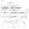
図1に本発明の実施例に関わるインクジェット記録装置の構成を示す。101はインクジェット記録装置全体を制御するMPU(マイクロプロセッシングユニット)、102はインクジェット記録装置内で一時的にデータを記憶しておくRAM(ランダムアクセスメモリー)、103は書き出し位置を計算するソフトウェアおよびデータを記憶するROM(リードオンリーメモリ)、104は入力されたデータおよび印字内容等を表示する表示装置、105は被印字物の幅、印字距離、書き出し位置、及び印字文字列の幅を入力するパネルである。 FIG. 1 shows the configuration of an ink jet recording apparatus according to an embodiment of the present invention. 101 is an MPU (microprocessing unit) that controls the entire inkjet recording apparatus, 102 is a RAM (random access memory) that temporarily stores data in the inkjet recording apparatus, and 103 is software and data for calculating the writing position. ROM (read-only memory) 104 for storing, a display device for displaying input data and printing contents, etc. 105 is a panel for inputting the width of the substrate, the printing distance, the writing position, and the width of the printing character string. is there.
106はカウンターで構成され印字開始のタイミングを調節する書き出しタイマ、107はインクジェット記録装置の印字動作を制御する印字制御回路、108は被印字物検出回路、109は被印字物の検知時間と入力された被印字物の長さから移動速度を計算する移動速度計測回路、120は計測された移動速度から、書出し時の文字信号を送るタイミングを決めるためのラインクロック信号を生成する書出しタイミング制御回路、121は印字文字列の幅を一定に制御するためのラインクロック信号を生成する印字幅制御回路、110は印字内容を文字信号にする文字信号発生回路である。
106 is a write-out timer composed of a counter that adjusts the print start timing, 107 is a print control circuit that controls the printing operation of the ink jet recording apparatus, 108 is a print object detection circuit, and 109 is a print object detection time. A moving speed measuring circuit for calculating a moving speed from the length of the printed material, a writing timing control circuit for generating a line clock signal for determining a timing for sending a character signal at the time of writing from the measured moving speed,
そして111はデータ等を送るバスライン、112はインクを噴出するノズル、113はノズルより噴出したインクが粒子になりそのインク粒子に電荷を加える帯電電極、114は帯電したインク粒子を偏向する偏向電極、115は印字に使用しないインクを回収するガター、116はガターより回収されたインクを再びノズルへ供給するポンプ、117と122は被印字物を検出するセンサ、118は印字の対象となる被印字物、119は被印字物を搬送するコンベアである。
111 is a bus line for sending data, 112 is a nozzle that ejects ink, 113 is a charging electrode that makes ink ejected from the nozzle into particles, and charges the ink particles, and 114 is a deflection electrode that deflects charged ink particles. 115 is a gutter that collects ink that is not used for printing, 116 is a pump that supplies the ink collected from the gutter to the nozzles again, 117 and 122 are sensors that detect the object to be printed, and 118 is the object to be printed. A
次に、印字内容入力から印字を完了するまでの一連の動作概要について述べる。
印字内容は、印字内容データをパネル105によって入力してRAM102に保存することで設定することが出来る。また、パネル105より設定された印字文字列の幅から縦列間の距離(ラインクロック信号1パルスあたりの移動距離)を決定し、RAM102に保存する。
Next, an outline of a series of operations from input of print contents to completion of printing will be described.
The print content can be set by inputting print content data through the
パネル105より設定された印字内容、印字フォーマットと縦列間距離から、ROM103に記憶されている移動速度計算プログラムによって、該当印字内容の最高印字速度を計算する。この最高印字速度によって生成されたラインクロック信号によって決定した書出し位置を基準にして位置が合うように制御する。
The maximum printing speed of the corresponding printing content is calculated by the moving speed calculation program stored in the
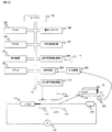
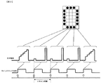
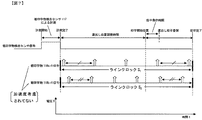
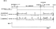
ここで、図2〜図4を用いてラインクロック信号について説明する。図2はラインクロック信号を生じさせるインクジェット記録装置の構成図であり、図3はラインクロック信号と印字スキャンの関係を示す図であり、図4はラインクロックの幅と被印字物の移動速度の関係を示した図である。 Here, the line clock signal will be described with reference to FIGS. 2 is a configuration diagram of an ink jet recording apparatus that generates a line clock signal, FIG. 3 is a diagram illustrating a relationship between the line clock signal and print scan, and FIG. 4 is a diagram illustrating the width of the line clock and the moving speed of the substrate. It is the figure which showed the relationship.
ラインクロック信号とは、被印字物の移動量に同期させて速度制御するためのロータリーエンコーダ等の信号発生装置201において、外部パルスを入力回路202によって装置に入力し、入力された外部パルスを分周回路203によって分周した信号に相当する信号である。
The line clock signal is a
信号発生装置を使用する場合は、この分周された信号を基に、文字信号を発生するタイミングを調整し印字を行う。図3に示す文字信号は、印字対象とする文字をドットパターンで表した印字文字における縦1列分の文字配列(ドットパターン配列)と対応しており、縦1列分の上下方向位置におけるドットの有無に対応するようにパルスの立上りを有する。これより、ラインクロック信号は、図3に示すようにパルスの立上がりもしくは立下りをトリガにして、1パルスあたり1スキャン(縦1列分)の文字信号を発生させるための信号であるといえる。 When a signal generator is used, printing is performed by adjusting the timing for generating a character signal based on the divided signal. The character signal shown in FIG. 3 corresponds to a character array (dot pattern array) for one vertical column in a print character in which a character to be printed is represented by a dot pattern. It has a rising edge of the pulse so as to correspond to the presence or absence. Accordingly, it can be said that the line clock signal is a signal for generating a character signal of one scan per pulse (for one vertical column) triggered by the rise or fall of a pulse as shown in FIG.
ラインクロック信号の周期は1スキャンあたりの移動時間となるように生成され、入力された印字文字列の長さとなるように印字制御及び書き出し位置の制御を行う。そのラインクロック信号のスキャン間隔(パルスの周期)から、被印字物の移動速度がわかり、図4に示すようにスキャン間隔が長いほど被印字物の移動速度は遅く、短いほど移動速度が速いことを示すものである。 The cycle of the line clock signal is generated so as to be the movement time per scan, and the print control and the write position control are performed so as to be the length of the input print character string. From the scanning interval (pulse period) of the line clock signal, the moving speed of the printed material can be determined. As shown in FIG. 4, the moving speed of the printed material is slower as the scanning interval is longer, and the moving speed is faster as the scanning interval is shorter. Is shown.
ラインクロック信号は以下のように生成される。まず、被印字物検出センサ117は制御対象となる被印字物を検出すると、被印字物検知回路108によって被印字物の遮光時間を計測する。移動速度計測回路109にてパネル105より設定された被印字物の長さと計測された遮光時間に基づいて被印字物の移動速度を計測する。
The line clock signal is generated as follows. First, when the printing
次に、被印字物の移動速度と設定時に決定された最高印字速度との比に基づいてラインクロック信号を生成する。その生成されたラインクロック信号バスライン111を通じてRAM102に保存される。
Next, a line clock signal is generated based on a ratio between the moving speed of the printing object and the maximum printing speed determined at the time of setting. The generated line clock
被印字物検出センサ117から書出しまでの距離を、記憶された縦列間の距離で除算し、被印字物検出センサ117から書出しまでの必要なラインクロックパルス数(1)を算出できる。
The required number of line clock pulses (1) from the printing
また、文字信号発生回路110から生成させる文字信号の発生から被印字物への書出し粒子の着弾までの被印字物の移動量を、パネル105によって入力された印字距離から求めた飛行粒子時間と計測した移動速度から算出する。その移動量を縦列間の距離で除算ラインクロックパルス数(2)を算出する。
Further, the flying particle time obtained from the printing distance inputted by the
ラインクロックパルス(1)と(2)の合計を、書出しタイマ106でパルス数を数える際のカウンター値とする。書出しタイマ106はラインクロック信号のパルス1つにつき1つずつカウンター値からカウントダウンを始める。書き出しタイマ106のカウンターがカウントを終了すると、書き出しタイマ106からタイムアップの指令がMPU101へ届く。
The sum of the line clock pulses (1) and (2) is used as a counter value when the
MPU101は、タイムアップ指令を受けて印字開始タイミングの指令を発生させると共に、MPU101はRAM102に記憶している印字内容を、バスライン112を介して文字発生回路110へ送る。
The
文字信号発生回路110は送られてきた印字内容を文字信号に変更し、ノズル112から噴出し、帯電電極113内で粒子化したインク粒子に、該文字信号に応じた帯電電圧が印加される。
The character
印字制御回路107はバスライン111を介して、上記帯電電圧の印加制御を行うための帯電信号を帯電電極113へ送出するタイミングをコントロールする。この制御によって帯電したインク粒子は偏向電極114により偏向され、コンベヤ119によって搬送され被印字物118hへ向かって飛翔し、付着して印字される。印字に使用されなかったインク粒子はガター115より回収され、ポンプ116によって再びノズル112へ供給される。
The
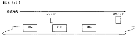
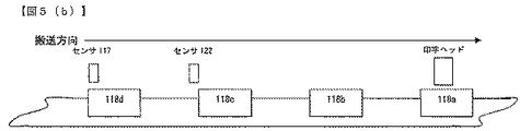
ここからは図5〜図8、図10を用いて、従来の技術と発明のラインクロック生成時の違いについて述べる。図5(a)は被印字物検出センサを1つ用いた時の本発明の被印字物搬送の図であり、図5(b)は被印字物検出センサを2つ用いた時の本発明の被印字物搬送の図であり、図6は被印字物への書出し制御における従来技術と本発明の比較図である。図7は、従来技術におけるラインクロック信号生成のタイムチャートである。図8は、本発明におけるラインクロック信号生成のタイムチャートである。図10は、本発明の制御処理フローチャートである。 From here, the difference between the prior art and the line clock generation of the invention will be described with reference to FIGS. FIG. 5A is a diagram of conveyance of a printing material according to the present invention when one printing material detection sensor is used, and FIG. 5B is a diagram of the present invention when two printing material detection sensors are used. FIG. 6 is a comparison diagram of the prior art and the present invention in the writing start control on the printed material. FIG. 7 is a time chart of line clock signal generation in the prior art. FIG. 8 is a time chart of line clock signal generation in the present invention. FIG. 10 is a control processing flowchart of the present invention.
被印字物118が搬送される様子は図5(a)に示すように、被印字物118は被印字物118aを先頭に、被印字物118b、被印字物118cと搬送される。
As shown in FIG. 5A, the
最初に、従来の技術について、被印字物118aが被印字物検出センサ117を通過してから被印字物118bの印字が完了するまでのラインクロック信号の生成を図7に示し、以下に説明する。
First, with respect to the prior art, the generation of a line clock signal from when the printing object 118a passes through the printing
まず、被印字物118aが被印字物検出センサ117を通過する際の計測時間から求めた移動速度V1に相当するラインクロック信号S1を生成する。被印字物118aは被印字物検出センサ117での計測後から印字完了まで、ラインクロック信号S1によって動作する。
First, the line clock signal S 1 corresponding to the moving speed V 1 obtained from the measurement time when the printed material 118 a passes the printed
次に、被印字物118aの後方から一定の距離をおいて搬送される被印字物118bが被印字物検出センサ117を通過する際の計測時間から求めた移動速度V2に相当するラインクロック信号S2を生成する。被印字物118bは、被印字物検出センサ117計測後から印字完了までラインクロック信号S2によって動作する。
Next, the line clock signal corresponding to the moving speed V 2 obtained from the measurement time when the printed
被印字物118aと被印字物118bのラインクロック信号生成方法は同じであり、被印字物118b以後に搬送される被印字物118も全て同様の方法でラインクロック信号を生成する。
The line clock signal generation method for the printing object 118a and the
このとき従来の技術では、被印字物aの書出し位置を計算する際、被印字物118aが被印字物検出センサ117を通過する際に計測されたデータのみを用いてラインクロック信号を生成するため、被印字物検出センサ117を通過するタイミングから印字開始タイミングまでの間に被印字物118aが加減速して移動する場合の書出し位置の調整には対応しておらず、被印字物の移動速度が加減速した場合には書出し位置にずれが生じ、印字品質が低下する問題があった。同様に、被印字物118b以後においても、対応する被印字物の移動速度が加減速することで当該問題が生じるものである。
At this time, in the conventional technique, when calculating the writing position of the printing object a, the line clock signal is generated using only the data measured when the printing object 118a passes the printing
図6は、印字ヘッド部におけるコンベアの移動速度を示す。左側に記載するのが従来技術のグラフであり、右側に記載するのが本発明のグラフである。ただし、被印字物の移動速度の絶対値が異なっても、センサ計測後から書出し粒子着弾までに速度が変化することが無ければ、従来の技術でも書出し位置を調整することは可能だが、センサ計測後から書出し粒子着弾までに速度が変化する場合は、書出し調整不可であることを示す。 FIG. 6 shows the moving speed of the conveyor in the print head unit. The graph on the left side is the graph of the prior art, and the graph on the right side is the graph of the present invention. However, even if the absolute value of the moving speed of the substrate is different, if the speed does not change from sensor measurement to writing particle landing, it is possible to adjust the writing position with conventional technology, but sensor measurement If the speed changes after the writing particle landing after that, it indicates that the writing adjustment is impossible.
次に、本発明のラインクロック信号生成について述べる。RAM102に保存された複数の移動速度データを、バスライン111を介して、書出しタイミング制御回路120へ送り、加速度を考慮した移動速度を計算する。
Next, line clock signal generation according to the present invention will be described. A plurality of movement speed data stored in the
その移動速度に応じて生成されたラインクロック信号のデータをバスライン111を介して、書出しタイマ106へセットする。以下に、書出しタイミング制御回路120による加速度を考慮した制御について述べる。
Data of the line clock signal generated according to the moving speed is set to the
図10に本発明の書出し印字制御フローチャートの概要を示す。
まず、印字内容及び印字条件を設定し(S1)、設定された値から最高印字速度を算出する(S2)。そして後述する方法で被印字物の第1の移動速度V1と第2の移動速度V2を算出し(S3、S4)、この第1及び第2の移動速度に基づいて平均移動速度V12と加速度aを求める(S5)。これより、平均移動速度V12と最高印字速度との比から第1のラインクロック信号を生成し(S6)、第1のラインクロック信号に基づいて上述のラインクロックパルス数を算出し、パルスをカウントするタイマの設定値とする(S7)。
FIG. 10 shows an outline of a writing / printing control flowchart of the present invention.
First, the printing contents and printing conditions are set (S1), and the maximum printing speed is calculated from the set values (S2). Then, a first moving speed V 1 and a second moving speed V 2 of the printing material are calculated by a method described later (
さらに、被印字物への印字開始地点における移動速度V3を加速度aから算出し(S8)、移動速度V3と最高印字速度との比から第2のラインクロック信号を生成し(S9)、タイマのパルスカウントが設定したラインクロックパルス数に達した際を印字開始タイミングとし、第2のラインクロック信号に従って印字を開始する(S10)。 Moreover, to calculate the moving velocity V 3 in the print start point of the printing object from the acceleration a (S8), from the ratio of the moving speed V 3 and the maximum printing speed to generate a second line clock signal (S9), When the pulse count of the timer reaches the set number of line clock pulses, the print start timing is set, and printing is started in accordance with the second line clock signal (S10).
図10のフローチャートにおける被印字物の加速度の算出について2通りの方法を以下に説明する。 Two methods for calculating the acceleration of the substrate in the flowchart of FIG. 10 will be described below.
まず、2つの被印字物の移動速度から加速度を求める場合について説明する。この場合、図5(a)に示したように、被印字物の搬送経路においては被印字物検出センサが1つ備えられていればよいものである。図8を用いて、被印字物118aが被印字物検出センサ117を通過してから、被印字物118bの印字が完了するまでのラインクロック信号の生成を以下に説明する。
First, the case where the acceleration is obtained from the moving speeds of the two printing objects will be described. In this case, as shown in FIG. 5A, it is only necessary to provide one substrate detection sensor in the conveyance path of the substrate. The generation of a line clock signal from when the printing material 118a passes through the printing
最初に移動する被印字物118aは、加速度を算出できないので、被印字物118aは被印字物検出センサ117を通過する計測時間から求めた移動速度V1のみによってラインクロック信号を生成し、被印字物118aは被印字物検出センサ117での計測後から印字完了まで、ラインクロック信号S1によって動作する。
Printing object 118a to first move, can not calculate the acceleration, the printing object 118a generates a line clock signal by only moving speed V 1 determined from the measurement time through the printing
次に被印字物118bでは加速度を考慮する。ここでは加速度を求めるために2つの被印字物の移動速度を必要とするため、被印字物検出センサ117の通過時点での被印字物118aと被印字物118bによる移動速度V1および移動速度V2を算出する。ここで、移動速度V1によって生成されたラインクロック信号をS1とする。2つの被印字物の移動速度と、被印字物検出回路108で検出する被印字物検出センサの位置情報とによって、被印字物検出センサで計測する2つの被印字物の計測時間の時間差から演算し、被印字物118bの加速度を算出する。
Next, acceleration is taken into consideration for the printed
次に、算出した加速度および上記計算された被印字物118bの移動速度V2から被印字物118bが印字位置の移動速度V2’を算出可能となる。そして被印字物検出センサ位置での速度V2と印字位置での速度V2’から、被印字物検出センサ117から印字位置間の平均速度V2’’を計算し、平均速度V2’’と該当印字内容(決定された印字文字列の幅)での印字を可能とする最高印字速度の比から、書出しタイミング制御回路120でラインクロック信号S2を生成する。
Next, the
書出し位置の変化を抑制するために、被印字物118bが被印字物検出センサ117から印字位置に移動するまでは、ラインクロック信号S2を書出しタイマ106にセットし、カウンターがカウントを終了すると、書き出しタイマタイムアップの指令がMPU101へ届く。指令が届いたら、ラインクロック信号S2’の周期に切り替えて、印字開始から印字完了まで制御することで、印字文字列の幅の変化を抑制する。
To suppress a change in writing position, when the
被印字物118b以後に搬送される被印字物118は、被印字物118bと同様に、前方の被印字物の移動速度から加速度を算出し、加減速にも対応可能なラインクロック信号を生成することができる。
Similar to the printed
次に、図9を用いて2つのセンサを使用して被印字物の移動速度から加速度を求める場合について説明する。この場合は、最初の被印字物から加速度を考慮することが可能である。図9には被印字物118aが被印字物検出センサ117を通過してから、印字が完了するまでの様子を示す。
Next, the case where the acceleration is obtained from the moving speed of the printing object using two sensors will be described with reference to FIG. In this case, it is possible to consider acceleration from the first substrate. FIG. 9 shows a state from when the printing object 118a passes through the printing
この場合、図5(b)に示したように、被印字物の搬送経路においては被印字物検出センサが2つ備えられているものとする。加速度を求めるには、2つの被印字物の移動速度が必要なので、1つの被印字物118aが、2つの地点に設けられた被印字物検出センサ117と印字物検出センサ122を通過する時点での移動速度V0および移動速度V1を算出する。その2つの速度と2つの被印字物検出センサで計測する被印字物の計測時間の時間差から演算し加速度を算出する。
In this case, as shown in FIG. 5B, it is assumed that two print object detection sensors are provided in the conveyance path of the print object. In order to obtain the acceleration, the movement speed of the two printed materials is necessary, and therefore, when one printed material 118a passes the printed
次に、算出した加速度から被印字物118aの印字位置での移動速度V1’を算出する。印字位置での移動速度V1’と該当印字内容における最高印字速度の比から印字幅制御回路121によってラインクロック信号S1’を生成する。
Next, the moving speed V 1 ′ at the printing position of the substrate 118a is calculated from the calculated acceleration. The line clock signal S 1 ′ is generated by the print
そして、センサ位置での速度V1と印字位置での速度V1’から平均速度V1’’を計算する。平均速度V1’’と該当印字内容の最高速度の比から、書出しタイミング制御回路120でラインクロック信号S1を生成する。書出し位置の変化を抑制するために、被印字物118aが被印字物検出センサ122から印字位置に移動するまでは、ラインクロック信号S1を書出しタイマ106にセットし、カウンターがカウントを終了すると、書き出しタイマタイムアップの指令がMPU101へ届く。指令が届いたら、ラインクロック信号S1’の周期に切り替えて、印字開始から印字完了まで制御することで、印字文字列の幅の変化を抑制する。
Then, to calculate the 'average speed V 1 from' the speed V 1 of the at speed V 1 and the printing position of the sensor position. From the ratio between the average speed V 1 ″ and the maximum speed of the corresponding print content, the write
被印字物118a以後に搬送される被印字物118は、被印字物118aと同様に、2つのセンサによる被印字物の移動速度から加速度を算出し、加速度を考慮したラインクロック信号を生成することができる。
Similar to the printing object 118a, the
以上の実施の形態によれば、被印字物が加減速する場合においても、書出し位置のずれを抑制した印字を可能にし、印字品質を向上することができるインクジェット記録装置を提供することができる。 According to the above embodiment, it is possible to provide an ink jet recording apparatus that can perform printing while suppressing the deviation of the writing position and improve the printing quality even when the printing material is accelerated or decelerated.
101・・・MPU
102・・・RAM
103・・・ROM
104・・・表示装置
105・・・パネル
106・・・書出しタイマ
107・・・印字制御装置
108・・・被印字物検知回路
109・・・移動速度計測回路
110・・・文字信号発生回路
111・・・バスライン
112・・・ノズル
113・・・帯電電極
114・・・偏向電極
115・・・ガター
116・・・ポンプ
117、122・・・被印字物検出センサ
118・・・被印字物
119・・・コンベア
120・・・書出しタイミング制御回路
121・・・印字幅制御回路
201・・・信号発生装置
202・・・入力回路
203・・・分周回路
101 ... MPU
102 ... RAM
103 ... ROM
104 ...
Claims (9)
前記インク容器に接続され、インクを吐出するノズルと、
前記ノズルから吐出されて印字に使用されるインクを帯電する帯電電極と、
前記帯電電極で帯電されたインクを偏向する偏向電極と、
印字に使用されないインクを回収するガターと、を備えたインクジェット記録装置であって、
第1のラインクロック信号を生成する書出しタイミング制御回路と、
第2のラインクロック信号を生成する印字幅制御回路と、
制御部と、
被印字物の基準位置での通過時間を検出する検出部と、
被印字物の移動速度を算出する移動速度計測回路と、を有し、
前記制御部で、第1のラインクロック信号に基づいて被印字物への書出し開始位置を制御し、
被印字物が印字開始タイミングに達した際に、第2のラインクロック信号に基づいて印字内容の文字列の幅調整を行い、印字制御し、
前記検出部で得られる検出情報に基づいて前記移動速度計測回路で被印字物の第1の地点での移動速度と、第2の地点での移動速度を算出するとともに、前記第1及び第2の移動速度から平均移動速度を算出し、
前記平均移動速度と、設定された情報に基づく被印字物の最高移動速度との比に基づいて前記書出しタイミング制御回路で第1のラインクロック信号を生成し、
前記移動速度計測回路で被印字物の前記第1の地点での移動速度と、前記第2の地点での移動速度と、被印字物が前記第1と第2の地点間を通過する時間に基づいて被印字物の加速度を算出し、前記加速度に基づいて印字開始タイミングでの移動速度を算出し、前記印字開始タイミングでの移動速度と、設定された情報に基づく被印字物の最高移動速度との比に基づいて前記印字幅制御回路で第2のラインクロック信号を生成することを特徴とするインクジェット記録装置。 An ink container for containing ink for printing on a print object;
A nozzle connected to the ink container and ejecting ink;
A charging electrode for charging ink discharged from the nozzle and used for printing;
A deflection electrode for deflecting ink charged by the charging electrode;
An ink jet recording apparatus comprising: a gutter that collects ink that is not used for printing;
A write timing control circuit for generating a first line clock signal;
A print width control circuit for generating a second line clock signal;
A control unit;
A detection unit for detecting a passing time at the reference position of the substrate;
A moving speed measuring circuit for calculating the moving speed of the substrate ,
In the control unit, based on the first line clock signal, the writing start position to the printing object is controlled,
When the printed material reaches the print start timing, the width of the character string of the print content is adjusted based on the second line clock signal, and the print control is performed .
Based on the detection information obtained by the detection unit, the moving speed measuring circuit calculates the moving speed of the printed material at the first point and the moving speed at the second point, and the first and second points. Calculate the average movement speed from the movement speed of
Generating a first line clock signal in the writing timing control circuit based on a ratio between the average moving speed and the maximum moving speed of the printing material based on the set information;
In the moving speed measuring circuit, the moving speed of the printed material at the first point, the moving speed at the second point, and the time during which the printed material passes between the first and second points. Based on the acceleration, the movement speed at the print start timing is calculated based on the acceleration. The movement speed at the print start timing and the maximum movement speed of the print medium based on the set information. And a second line clock signal is generated by the print width control circuit based on the ratio of .
前記移動速度計測回路で、
第1の被印字物の第1の地点での移動速度と、第2の被印字物の第1の地点での移動速度と、被印字物が前記第1と第2の地点間を通過する時間とに基づいて第2の被印字物の加速度を算出し、
前記加速度に基づいて、前記第2の被印字物の印字開始タイミングでの移動速度を求め、前記第2の被印字物の印字開始タイミングでの移動速度と、設定された情報に基づく第2の被印字物の最高移動速度との比に基づいて第2のラインクロック信号を生成し、
前記第2の被印字物の第1の地点での移動速度と、第2の地点での移動速度とから平均移動速度を算出し、
前記平均移動速度と、設定された情報に基づく被印字物の最高移動速度との比に基づいて第1のラインクロック信号を生成し、
前記第1のラインクロック信号と前記第2のラインクロック信号に基づいて前記第2の被印字物の印字制御を行うことを特徴とするインクジェット記録装置。 The inkjet recording apparatus according to claim 1 ,
In the moving speed measuring circuit,
The moving speed of the first printed material at the first point, the moving speed of the second printed material at the first point, and the printed material pass between the first and second points. And calculating the acceleration of the second substrate based on the time,
Based on the acceleration, a moving speed at the printing start timing of the second printing material is obtained, and a moving speed at the printing start timing of the second printing material and a second information based on the set information. Generating a second line clock signal based on the ratio to the maximum moving speed of the substrate;
An average moving speed is calculated from the moving speed at the first point of the second printing material and the moving speed at the second point;
Generating a first line clock signal based on a ratio between the average moving speed and a maximum moving speed of the printing material based on the set information;
An ink jet recording apparatus that performs printing control of the second printing object based on the first line clock signal and the second line clock signal.
パルス数をカウントするタイマを有し、
前記制御部で、検出部の位置から印字開始時までに被印字物が移動する距離を前記第1のラインクロック信号の1パルスあたりの移動距離で除算し、ラインクロックパルス数を算出し、
前記書出しタイマでパルス数をカウントし、カウント値が前記ラインクロックパルス数に達した際に、前記制御部で印字を開始することを特徴とするインクジェット記録装置。 The inkjet recording apparatus according to claim 1 ,
Has a timer to count the number of pulses,
In the control unit, the distance that the substrate is moved from the position of the detection unit to the start of printing is divided by the movement distance per pulse of the first line clock signal to calculate the number of line clock pulses,
An ink jet recording apparatus, wherein the number of pulses is counted by the writing timer, and printing is started by the control unit when the count value reaches the number of line clock pulses.
前記検出部は、被印字物を検知し、被印字物の通過時間を検出するセンサであることを特徴とするインクジェット記録装置。 The inkjet recording apparatus according to claim 1 ,
The ink-jet recording apparatus, wherein the detection unit is a sensor that detects a printed material and detects a passage time of the printed material.
前記検出部は被印字物の移動量によって信号を発生するエンコーダであることを特徴とするインクジェット記録装置。 The inkjet recording apparatus according to claim 1 ,
The ink jet recording apparatus according to claim 1, wherein the detection unit is an encoder that generates a signal according to the amount of movement of the substrate.
前記インク容器に接続され、インクを吐出するノズルと、
前記ノズルから吐出されて印字に使用されるインクを帯電する帯電電極と、
前記帯電電極で帯電されたインクを偏向する偏向電極と、
印字に使用されないインクを回収するガターと、
制御部と、
を備えたインクジェット記録装置の印字制御方法であって、
被印字物の移動速度に基づいて第1のラインクロック信号と第2のラインクロック信号を生成し、
前記第1のラインクロック信号に基づいて被印字物への書出し開始位置を制御し、
被印字物が印字開始タイミングに達した際に、第2のラインクロック信号に基づいて印字内容の文字列の幅調整を行い、印字制御し、
検出手段で被印字物の基準位置での通過時間を検出し、
被印字物の通過時間と設定された被印字物の長さとから被印字物の移動速度を算出し、
被印字物の第1の地点での移動速度と、第2の地点での移動速度とから平均移動速度を算出し、
前記平均移動速度と、設定された情報に基づく被印字物の最高移動速度との比に基づいて第1のラインクロック信号を生成し、
被印字物の前記第1の地点での移動速度と、前記第2の地点での移動速度と、被印字物が前記第1と第2の地点間を通過する時間に基づいて被印字物の加速度を算出し、
前記加速度に基づいて印字開始タイミングでの移動速度を算出し、
前記印字開始タイミングでの移動速度と、設定された情報に基づく被印字物の最高移動速度との比に基づいて第2のラインクロック信号を生成することを特徴とするインクジェット記録装置の印字制御方法。 An ink container for containing ink for printing on a print object;
A nozzle connected to the ink container and ejecting ink;
A charging electrode for charging ink discharged from the nozzle and used for printing;
A deflection electrode for deflecting ink charged by the charging electrode;
A gutter for collecting ink that is not used for printing;
A control unit;
A printing control method for an inkjet recording apparatus comprising:
Generating a first line clock signal and a second line clock signal based on the moving speed of the substrate;
Based on the first line clock signal, the writing start position to the substrate is controlled,
When the printed material reaches the print start timing, the width of the character string of the print content is adjusted based on the second line clock signal, and the print control is performed .
The detection means detects the passage time at the reference position of the substrate,
Calculate the moving speed of the substrate from the passage time of the substrate and the set length of the substrate,
An average moving speed is calculated from the moving speed at the first point of the substrate and the moving speed at the second point;
Generating a first line clock signal based on a ratio between the average moving speed and a maximum moving speed of the printing material based on the set information;
Based on the moving speed of the printed material at the first point, the moving speed at the second point, and the time during which the printed material passes between the first and second points. Calculate acceleration,
Calculate the movement speed at the print start timing based on the acceleration,
A printing control method for an ink jet recording apparatus, wherein a second line clock signal is generated based on a ratio between a moving speed at the printing start timing and a maximum moving speed of a printing object based on set information. .
検出手段を複数有し、複数の検出手段の検出情報に基づいて、第1、第2の地点での被印字物の移動速度を算出し、
前記第1、第2の移動速度と、被印字物が前記第1と第2の地点間を通過する時間に基づいて被印字物の加速度を算出することを特徴とするインクジェット記録装置の印字制御方法。 A printing control method for an inkjet recording apparatus according to claim 6 ,
A plurality of detection means, based on the detection information of the plurality of detection means, to calculate the moving speed of the substrate to be printed at the first and second points;
Printing control of an ink jet recording apparatus, wherein the acceleration of the printing material is calculated based on the first and second moving speeds and the time during which the printing material passes between the first and second points. Method.
第1の被印字物の第1の地点での移動速度と、第2の被印字物の第1の地点での移動速度と、被印字物が前記第1と第2の地点間を通過する時間とに基づいて第2の被印字物の加速度を算出し、
前記加速度に基づいて、前記第2の被印字物の印字開始タイミングでの移動速度を求め、前記第2の被印字物の印字開始タイミングでの移動速度と、設定された情報に基づく第2の被印字物の最高移動速度との比に基づいて第2のラインクロック信号を生成し、
前記第2の被印字物の第1の地点での移動速度と、第2の地点での移動速度とから平均移動速度を算出し、
前記平均移動速度と、設定された情報に基づく被印字物の最高移動速度との比に基づいて第1のラインクロック信号を生成することを特徴とするインクジェット記録装置の印字制御方法。 A printing control method for an inkjet recording apparatus according to claim 6 ,
The moving speed of the first printed material at the first point, the moving speed of the second printed material at the first point, and the printed material pass between the first and second points. And calculating the acceleration of the second substrate based on the time,
Based on the acceleration, a moving speed at the printing start timing of the second printing material is obtained, and a moving speed at the printing start timing of the second printing material and a second information based on the set information. Generating a second line clock signal based on the ratio to the maximum moving speed of the substrate;
An average moving speed is calculated from the moving speed at the first point of the second printing material and the moving speed at the second point;
A printing control method for an ink jet recording apparatus, comprising: generating a first line clock signal based on a ratio between the average moving speed and a maximum moving speed of a printing material based on set information.
検出手段で被印字物を検出した時から印字開始時までに被印字物が移動する距離を、前記第1のラインクロック信号の1パルスあたりの移動距離で除算して、ラインクロックパルス数を算出し、
パルスカウント手段でラインクロックパルス数をカウントし、カウント値が前記ラインクロックパルス数に達した際に、印字開始することを特徴とするインクジェット記録装置の印字制御方法。 A printing control method for an inkjet recording apparatus according to claim 6 ,
The number of line clock pulses is calculated by dividing the distance that the printed material moves from the time when the printed material is detected by the detecting means until the start of printing by the moving distance per pulse of the first line clock signal. And
A printing control method for an ink jet recording apparatus, wherein the number of line clock pulses is counted by a pulse counting means, and printing is started when the count value reaches the number of line clock pulses.
Priority Applications (5)
| Application Number | Priority Date | Filing Date | Title |
|---|---|---|---|
| JP2012078876A JP5779534B2 (en) | 2012-03-30 | 2012-03-30 | Inkjet recording apparatus and printing control method |
| ES13154941.2T ES2549147T3 (en) | 2012-03-30 | 2013-02-12 | Inkjet recorder and print control method |
| EP13154941.2A EP2644384B1 (en) | 2012-03-30 | 2013-02-12 | Ink-jet recording apparatus and printing control method |
| US13/766,500 US8974029B2 (en) | 2012-03-30 | 2013-02-13 | Ink-jet recording apparatus and printing control method |
| CN201310058734.0A CN103358701B (en) | 2012-03-30 | 2013-02-25 | Ink-jet recording apparatus and printing control method |
Applications Claiming Priority (1)
| Application Number | Priority Date | Filing Date | Title |
|---|---|---|---|
| JP2012078876A JP5779534B2 (en) | 2012-03-30 | 2012-03-30 | Inkjet recording apparatus and printing control method |
Publications (2)
| Publication Number | Publication Date |
|---|---|
| JP2013208727A JP2013208727A (en) | 2013-10-10 |
| JP5779534B2 true JP5779534B2 (en) | 2015-09-16 |
Family
ID=47683623
Family Applications (1)
| Application Number | Title | Priority Date | Filing Date |
|---|---|---|---|
| JP2012078876A Active JP5779534B2 (en) | 2012-03-30 | 2012-03-30 | Inkjet recording apparatus and printing control method |
Country Status (5)
| Country | Link |
|---|---|
| US (1) | US8974029B2 (en) |
| EP (1) | EP2644384B1 (en) |
| JP (1) | JP5779534B2 (en) |
| CN (1) | CN103358701B (en) |
| ES (1) | ES2549147T3 (en) |
Families Citing this family (11)
| Publication number | Priority date | Publication date | Assignee | Title |
|---|---|---|---|---|
| JP6058938B2 (en) * | 2012-07-30 | 2017-01-11 | 株式会社日立産機システム | Inkjet recording apparatus and printing control method |
| CN103761807B (en) * | 2013-12-27 | 2016-02-17 | 广东金赋信息科技有限公司 | A kind of bill error prevention device and system |
| EP3088190B1 (en) | 2015-04-28 | 2020-03-11 | HP Scitex Ltd | Print unit activation by means of a clock unit |
| WO2018038036A1 (en) * | 2016-08-22 | 2018-03-01 | 株式会社日立産機システム | Inkjet recording device and inkjet recording device control method |
| GB2554926A (en) * | 2016-10-14 | 2018-04-18 | Domino Uk Ltd | Improvements in or relating to continuous printers |
| CN109514997B (en) * | 2019-01-22 | 2024-02-20 | 莱芜钢铁集团有限公司 | Diaphragm pump action frequency adjusting method, system and controller |
| US11407218B2 (en) * | 2019-02-06 | 2022-08-09 | Hewlett-Packard Development Company, L.P. | Identifying random bits in control data packets |
| SG11202107305QA (en) | 2019-02-06 | 2021-08-30 | Hewlett Packard Development Co Lp | Integrated circuit with address drivers for fluidic die |
| EP4289623A3 (en) | 2019-02-06 | 2024-02-28 | Hewlett-Packard Development Company L.P. | Print component with memory array using intermittent clock signal |
| JP7429180B2 (en) * | 2020-10-15 | 2024-02-07 | 株式会社日立産機システム | Inkjet recording device and method of controlling the inkjet recording device |
| CN112776492B (en) * | 2020-12-31 | 2022-11-08 | 苏州工业园区鑫海胜电子有限公司 | Printing method without physical grating |
Family Cites Families (7)
| Publication number | Priority date | Publication date | Assignee | Title |
|---|---|---|---|---|
| JPS5763272A (en) * | 1980-10-04 | 1982-04-16 | Ricoh Co Ltd | Character height adjusting method in charge deflection type ink jet recording apparatus |
| JPH01168457A (en) * | 1987-12-25 | 1989-07-03 | Hitachi Ltd | Printing controller of ink jet recorder |
| JPH06305125A (en) | 1993-04-22 | 1994-11-01 | Hitachi Ltd | Ink jet recording apparatus |
| JP2000289253A (en) * | 1999-04-08 | 2000-10-17 | Canon Inc | Recording device and recording method |
| US7475974B2 (en) | 2005-03-11 | 2009-01-13 | Hitachi Industrial Equipment Co., Ltd. | Inkjet recording apparatus |
| JP2008114471A (en) * | 2006-11-06 | 2008-05-22 | Hitachi Industrial Equipment Systems Co Ltd | Inkjet printer |
| JP5277313B2 (en) | 2009-06-24 | 2013-08-28 | 株式会社日立産機システム | Inkjet recording device |
-
2012
- 2012-03-30 JP JP2012078876A patent/JP5779534B2/en active Active
-
2013
- 2013-02-12 EP EP13154941.2A patent/EP2644384B1/en active Active
- 2013-02-12 ES ES13154941.2T patent/ES2549147T3/en active Active
- 2013-02-13 US US13/766,500 patent/US8974029B2/en active Active
- 2013-02-25 CN CN201310058734.0A patent/CN103358701B/en active Active
Also Published As
| Publication number | Publication date |
|---|---|
| JP2013208727A (en) | 2013-10-10 |
| ES2549147T3 (en) | 2015-10-23 |
| US8974029B2 (en) | 2015-03-10 |
| CN103358701B (en) | 2015-06-24 |
| US20130257949A1 (en) | 2013-10-03 |
| CN103358701A (en) | 2013-10-23 |
| EP2644384B1 (en) | 2015-08-12 |
| EP2644384A1 (en) | 2013-10-02 |
Similar Documents
| Publication | Publication Date | Title |
|---|---|---|
| JP5779534B2 (en) | Inkjet recording apparatus and printing control method | |
| JP6058938B2 (en) | Inkjet recording apparatus and printing control method | |
| CN101610908A (en) | inkjet recording device | |
| US10500843B2 (en) | Ink jet recording apparatus | |
| JP5743802B2 (en) | Inkjet recording device | |
| JP5277313B2 (en) | Inkjet recording device | |
| US20160325545A1 (en) | Inkjet Recording Device | |
| JP2016150502A (en) | Liquid discharge device and liquid discharge method | |
| JP6169918B2 (en) | Inkjet recording device | |
| JP6022391B2 (en) | Inkjet recording device | |
| JP7429180B2 (en) | Inkjet recording device and method of controlling the inkjet recording device | |
| JP2016150539A (en) | Inkjet recording device | |
| CN104070786A (en) | inkjet recording system | |
| JP5919159B2 (en) | Inkjet recording device | |
| JP7199109B1 (en) | Correction Method of Print Distortion in Inkjet Printer | |
| JP2012035602A (en) | Recorder, recording system, and recording module | |
| JP7058157B6 (en) | Inkjet recording device | |
| JPH1120172A (en) | Ink jet printing device | |
| JPS63154360A (en) | Inkjet recording device | |
| JP2006150657A (en) | Inkjet printing device | |
| JP2007044948A (en) | Inkjet recording device | |
| JP2016159435A (en) | Liquid ejection apparatus and liquid ejection method |
Legal Events
| Date | Code | Title | Description |
|---|---|---|---|
| A621 | Written request for application examination |
Free format text: JAPANESE INTERMEDIATE CODE: A621 Effective date: 20140604 |
|
| A521 | Request for written amendment filed |
Free format text: JAPANESE INTERMEDIATE CODE: A523 Effective date: 20140604 |
|
| A977 | Report on retrieval |
Free format text: JAPANESE INTERMEDIATE CODE: A971007 Effective date: 20150312 |
|
| A131 | Notification of reasons for refusal |
Free format text: JAPANESE INTERMEDIATE CODE: A131 Effective date: 20150317 |
|
| A521 | Request for written amendment filed |
Free format text: JAPANESE INTERMEDIATE CODE: A523 Effective date: 20150514 |
|
| TRDD | Decision of grant or rejection written | ||
| A01 | Written decision to grant a patent or to grant a registration (utility model) |
Free format text: JAPANESE INTERMEDIATE CODE: A01 Effective date: 20150616 |
|
| A61 | First payment of annual fees (during grant procedure) |
Free format text: JAPANESE INTERMEDIATE CODE: A61 Effective date: 20150713 |
|
| R150 | Certificate of patent or registration of utility model |
Ref document number: 5779534 Country of ref document: JP Free format text: JAPANESE INTERMEDIATE CODE: R150 |