JP5778904B2 - Touch input device - Google Patents
Touch input device Download PDFInfo
- Publication number
- JP5778904B2 JP5778904B2 JP2010215178A JP2010215178A JP5778904B2 JP 5778904 B2 JP5778904 B2 JP 5778904B2 JP 2010215178 A JP2010215178 A JP 2010215178A JP 2010215178 A JP2010215178 A JP 2010215178A JP 5778904 B2 JP5778904 B2 JP 5778904B2
- Authority
- JP
- Japan
- Prior art keywords
- touch
- touch pad
- finger
- display
- user
- Prior art date
- Legal status (The legal status is an assumption and is not a legal conclusion. Google has not performed a legal analysis and makes no representation as to the accuracy of the status listed.)
- Expired - Fee Related
Links
Images


Landscapes
- Position Input By Displaying (AREA)
- User Interface Of Digital Computer (AREA)
Description
本発明は、表示装置に表示される機能項目をタッチパッドの操作により選択及び決定可能なタッチ式入力装置に関する。 The present invention relates to a touch input device capable of selecting and determining function items displayed on a display device by operating a touch pad.
従来、例えば車両のセンターコンソール等の操作し易い場所に配設されたタッチ式入力装置とセンタークラスタパネル等の視認し易い場所に配設されたディスプレイとを備えるディスプレイシステムが提案されている(例えば、特許文献1参照)。ユーザは、タッチ式入力装置の操作面(タッチパッド)に触れる(タッチする)ことで、ディスプレイに表示された複数の機能項目から一つの機能項目を選択して、所望の画面を表示させたり車両の付帯装備を作動させたりする。従って、このディスプレイシステムによって、ディスプレイを視認しながら操作面を容易に操作することができ、車両の利便性が向上する。 2. Description of the Related Art Conventionally, a display system has been proposed that includes a touch-type input device disposed in an easily operable place such as a center console of a vehicle and a display disposed in an easily visible place such as a center cluster panel (for example, , See Patent Document 1). The user touches (touches) the operation surface (touch pad) of the touch input device to select one function item from a plurality of function items displayed on the display and display a desired screen. Activating the incidental equipment. Therefore, with this display system, the operation surface can be easily operated while visually recognizing the display, and the convenience of the vehicle is improved.
ところで、このようなディスプレイシステムでは、ユーザは、ディスプレイを視認しながらの操作となる。すなわちタッチ式入力装置の操作面を視認しない状態での操作となるため、ユーザの意志とは異なる入力(誤った入力)をするおそれがある。例えば、ユーザは、操作面上の指を右にスライドさせたつもりでも、実際には、右下にスライドさせているという場合である。この場合、誤った入力を取り消すなど正確に入力できていれば必要のない操作を強いられることがある。 By the way, in such a display system, the user performs an operation while visually recognizing the display. That is, since the operation is performed in a state where the operation surface of the touch input device is not visually recognized, there is a possibility that an input (incorrect input) different from the user's will is made. For example, even though the user intends to slide the finger on the operation surface to the right, the user actually slides the finger to the lower right. In this case, an unnecessary operation may be forced if an accurate input, such as canceling an erroneous input, can be made.
本発明は、こうした実状に鑑みてなされたものであり、その目的は、より正確な入力を行うことができるタッチ式入力装置を提供することにある。 The present invention has been made in view of such a situation, and an object thereof is to provide a touch-type input device capable of performing more accurate input.
上記課題を解決するために、請求項1に記載の発明は、入力情報に応じて複数の機能項目をディスプレイに表示させる制御手段と、外部へ露出した操作面を有するタッチパッドとを備え、前記制御手段は前記操作面に対するタッチ操作に基づいて、前記ディスプレイに表示される機能項目を選択及びその選択を決定するタッチ式入力装置において、前記タッチパッドには、前記操作面に対するタッチ位置を検出するセンサと、給電されることにより振動する圧電素子とを設け、前記制御手段は、前記ディスプレイに前記複数の機能項目を格子状となるように設定し、前記タッチパッド上の前記機能項目の表示位置及び隣接する機能項目同士が接続される位置に対応する領域を第1の領域と設定し、前記タッチパッド上の前記第1の領域に該当しない領域を第2の領域と設定し、前記タッチ位置が前記第1の領域に位置する場合には前記圧電素子への給電を行い、前記タッチ位置が前記第2の領域に位置する場合には前記圧電素子への給電を行わないことで、前記タッチパッド上の指を前記機能項目に対応する位置に案内することを要旨とする。 In order to solve the above-mentioned problem, the invention described in claim 1 includes control means for displaying a plurality of function items on a display in accordance with input information, and a touch pad having an operation surface exposed to the outside, In the touch-type input device that selects a function item displayed on the display and determines the selection based on a touch operation on the operation surface, the control unit detects a touch position on the operation surface on the touch pad. A sensor and a piezoelectric element that vibrates when supplied with power, and the control unit sets the plurality of function items on the display so as to form a grid, and the display position of the function items on the touchpad. And an area corresponding to a position where adjacent function items are connected to each other is set as a first area, and corresponds to the first area on the touchpad. Free area is set as the second area, when the touch position is located in the first region performs power supply to the piezoelectric element, when the touch position is located at the second region The gist is to guide the finger on the touch pad to a position corresponding to the function item by not supplying power to the piezoelectric element .
タッチパッドに指などで触れているときに同タッチパッドを高周波振動させると、同タッチパッドと指との間の抵抗が低減されることがわかっている。同構成によれば、制御手段は、センサが検出するタッチ位置が第1の領域に含まれる場合には、第2の領域に含まれる場合よりも高い周波数でタッチパッドが振動してタッチパッドと指との間の摩擦が低減するように圧電素子へ供給する電力の周波数を切り替える。これにより、第1の領域は第2の領域と比較して指にかかる摩擦が低い低摩擦領域となり、第2の領域は第1の領域と比較して指にかかる摩擦が高い高摩擦領域となる。このように構成したことにより、指にかかる摩擦の違いから、機能項目と対応する位置をタッチしているか否かを瞬間的に判断しやすい。 It has been found that if the touch pad is vibrated at a high frequency while touching the touch pad with a finger or the like, the resistance between the touch pad and the finger is reduced. According to this configuration, when the touch position detected by the sensor is included in the first region , the control unit vibrates the touch pad at a higher frequency than when the touch position is included in the second region. The frequency of the electric power supplied to the piezoelectric element is switched so that the friction with the finger is reduced . Thereby, the first region is a low friction region where the friction on the finger is low compared to the second region, and the second region is a high friction region where the friction on the finger is high compared to the first region. Become. With this configuration, it is easy to instantaneously determine whether or not the position corresponding to the function item is touched based on the difference in friction applied to the finger.
また、タッチパッドを指で操作しているとき、指がタッチパッド上の第1の領域にある場合には、圧電素子への給電を通じて同タッチパッドを高周波振動させる。指がタッチパッド上の第2の領域にある場合には、圧電素子へ給電しないことを通じて同タッチパッドパッドを振動させない。すなわち、機能項目の表示位置と対応する位置にあるときの指は、タッチパッド上をスムーズに移動し、反対に機能項目の表示位置からずれた位置にあるときの指は、タッチパッド上をスムーズに移動できない。これにより、ユーザは、タッチパッド上をスムーズに移動できるときに、機能項目を選択していることが容易にわかるので、タッチパッドを視認して、指の位置を確認することなく、所定のタッチ操作を通じて、その機能項目を正確に入力及び決定することができる。 Further, when the touch pad is operated with a finger, when the finger is in the first region on the touch pad, the touch pad is vibrated at a high frequency through power supply to the piezoelectric element. When the finger is in the second region on the touch pad, the touch pad pad is not vibrated through not supplying power to the piezoelectric element. In other words, the finger moves smoothly on the touch pad when it is at a position corresponding to the display position of the function item, and conversely, the finger moves smoothly on the touch pad when it is shifted from the display position of the function item. Cannot move to. As a result, when the user can move smoothly on the touch pad, the user can easily recognize that the function item is selected. Therefore, the user can visually recognize the touch pad and perform a predetermined touch without checking the finger position. Through the operation, the function item can be accurately input and determined.
また、タッチ操作の際、指先に係る摩擦抵抗が一様であれば、格子状に指をスライドさせていることを認識できる。一様でなければ、すなわち、指先に係る摩擦抵抗に変化が感じられるときには、指を格子状にスライドさせてないことが認識できる。特に、指先に係る摩擦抵抗が小さく指をスムーズに動かすことができる場合には、ユーザは自身の指を格子状にスライドさせていることを容易に認識することができる。反対に、指をスムーズに動かすことができない場合には、ユーザは指を格子状にスライドさせていないことを容易に認識することができる。 Further , when the frictional resistance related to the fingertip is uniform during the touch operation, it can be recognized that the finger is slid in a lattice shape. If it is not uniform, that is, if a change in the frictional resistance relating to the fingertip is felt, it can be recognized that the finger is not slid in a lattice pattern. In particular, if it can be moved smoothly frictional resistance is small finger of the fingertip, the user can easily recognize that the slide their finger in a grid. On the other hand, when the finger cannot be moved smoothly, the user can easily recognize that the finger is not slid in a lattice shape.
請求項2に記載の発明は、請求項1に記載のタッチ式入力装置において、前記タッチパッドの操作面は、無数の微小凹凸が形成された粗面であることを要旨とする。
The invention according to
同構成によれば、タッチパッドが粗面であることによって、同タッチパッドの振動の有無によって、同タッチパッド上をタッチ操作する指先に係る摩擦抵抗の変化が急激になる。これにより、ユーザは、指がスライドしやすいか否かを容易に認識することができるようになる。また、ユーザは指を格子状にスライドさせているか否かを容易に認識することができる。 According to this configuration, since the touch pad has a rough surface, a change in frictional resistance related to a fingertip that performs a touch operation on the touch pad becomes abrupt depending on whether the touch pad vibrates. Thus, the user can easily recognize whether or not the finger slides easily. Further, the user can easily recognize whether or not the finger is slid in a lattice shape.
本発明では、より正確な入力を行うことができるタッチ式入力装置を提供することができる。 In the present invention, it is possible to provide a touch input device capable of performing more accurate input.
(第1の実施形態)
以下、本発明のディスプレイシステムを車両に搭載した第1の実施形態を図面に従って説明する。
(First embodiment)
Hereinafter, a first embodiment in which a display system of the present invention is mounted on a vehicle will be described with reference to the drawings.
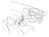
図1に示すように、ダッシュボード1の中央部(センタークラスタ)には、横長の長方形状のディスプレイ11が嵌め込まれている。ダッシュボードのディスプレイ11の周辺には、エアコンディショナ、オーディオ及びナビゲーションシステム等の車両の付帯機器を選択する複数個の図示しない選択スイッチが設けられている。これら複数個の選択スイッチのうちいずれか一つが操作された際、ディスプレイ11には、操作された選択スイッチに対応する付帯機器に応じた操作状況、又は単数個もしくは複数個の機能項目が表示される。例えばエアコンディショナに対応する選択スイッチが操作された場合には、その操作状況及び温度設定のための機能項目等がディスプレイ11に表示される。ナビゲーションシステムに対応する選択スイッチが操作された場合には、案内地図又は目的地設定等の機能項目がディスプレイ11に表示される。
As shown in FIG. 1, a horizontally long
センターコンソール2には、シフトレバー3の手前側にタッチ式入力装置12の入力部としてのタッチパッド13がその表面を露出させる態様で設けられている。タッチパッド13は、ディスプレイ11の縦と横の比率が同じ長方形状とされている。ユーザは、タッチパッド13の操作を通じて、ディスプレイ11に表示された所望の機能項目を選択し、所定の決定操作を行うことにより、付帯機器に所望の動作を実行させることが可能とされている。
The
図2に示すように、ディスプレイシステム10は、ディスプレイ11とタッチ式入力装置12とから構成される。タッチ式入力装置12は、タッチパッド13、感圧センサ14、圧電素子15、制御回路16、及び駆動回路17によって構成される。
As shown in FIG. 2, the
タッチパッド13は、ABS(Acrylonitrile Butadiene Styrene)樹脂からなる板部材である。タッチパッド13は、微小の凹凸が無数に形成された粗面(高摩擦表面)を外部に露出させた状態で設けられている。位置センシング部としての感圧センサ14は、タッチパッド13の露出面と反対側の面に固定され、同タッチパッド13に指が触れた際に生じる圧力によって、指が触れたタッチパッド13上のタッチ位置を検出するとともに、この位置情報を含む信号を生成する。圧電素子15は、感圧センサ14のタッチパッド13とは反対側の面に固定される。圧電素子15は、電力が供給されると高周波振動する。この振動は、感圧センサ14を介してタッチパッド13に伝播する。このように、タッチパッド13、感圧センサ14、及び圧電素子15は、一体とされている。
The
制御回路16には、エアコンディショナ、オーディオ及びナビゲーションシステム等の車両の付帯機器及びこれらに対応する選択スイッチが接続されている。制御回路16は、これら付帯機器に対応する選択スイッチが操作された場合は、各付帯機器に対応する画面(機能項目等)をディスプレイ11に表示させる。また、制御回路16は、感圧センサ14と電気的に接続されている。従って、制御回路16には、感圧センサ14から、位置情報を含む信号が伝達される。制御回路16は、ディスプレイ11に表示された機能項目とタッチパッド13におけるユーザの指が触れた位置とが対応する場合に、その機能項目を視覚的に強調して表示させる(機能項目の選択)。本例では、ディスプレイ11に四角枠状のカーソルが表示される。このカーソルは、タッチパッド13上の指が移動するのに合わせて各機能項目間を移動する。選択した機能項目を決定する場合には、機能項目が選択された状態で、タッチパッド13から指を離す。指がタッチパッド13から離れると、感圧センサ14から制御回路16への信号の送信が停止される。これにより、制御回路16は、選択されていた機能項目が決定された旨判定し、その機能項目に応じた所望の付帯機器を動作させる。
The
制御回路16は、駆動回路17を介して圧電素子15と電気的に接続されている。制御回路16は、ユーザの指がタッチパッド13に触れた位置に応じて、圧電素子15への電力の供給の有無を切り替える信号を生成して、これを駆動回路17へ送信する。駆動回路17は、制御回路16からの信号に基づき、圧電素子15への電力の供給を切り替える。電力が供給された圧電素子15は、高周波振動する。この振動は、一体とされているタッチパッド13にも伝播する。
The
上述したように、タッチパッド13の露出面には、無数の微小な凹凸がある。このため、ユーザがタッチパッド13の露出面を指でなぞると、その微小凹凸が摩擦抵抗となる。すなわち、タッチパッド13は、指をスライドさせにくくなっている。このような微小凹凸面を高周波振動させると、同微小凹凸面と指との間の摩擦抵抗が低減されることがわかっている。制御回路16は、感圧センサ14からの位置情報信号をもとに、摩擦抵抗を低減させる必要性の有無を判断する。摩擦抵抗の低減が必要と判断した場合には、制御回路16は、圧電素子15へ電力を供給する旨示す信号を生成して、これを駆動回路17に送信する。タッチパッド13が高周波振動することによって、タッチパッド13の露出面と指との間の摩擦抵抗が低減されるので、ユーザは指をスムーズに動かすことができる。
As described above, the exposed surface of the
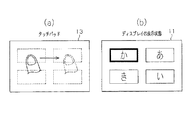
次に、このディスプレイシステム10の入力態様について説明する。説明の前提として、ユーザは、車両の付帯機器を選択するスイッチを操作しており、その付帯機器に対応する画面を制御回路16が、ディスプレイ11に表示させているものとする。ここでは、図3(b)に示すように、右上に「あ」、右下に「い」、左上に「か」、左下に「き」という横長の長方形状の機能項目がディスプレイ11の画面に表示されているものとする。図3(a)、図4(a)、図4(b)、及び図5に破線で示されるタッチパッド13上の長方形状の領域は、図3(b)に示されるディスプレイ11上の機能項目の位置と対応する。
Next, an input mode of the
図5は、図3(b)に示す機能項目が表示された場合のタッチパッド13において設定される低摩擦領域と高摩擦領域とを視覚的に示した模式図である。低摩擦領域は、制御回路16がタッチパッド13を高周波振動させるタッチ位置の範囲である。高摩擦領域は、制御回路16がタッチパッド13を振動させないタッチ位置の範囲である。高摩擦領域は、図5に網掛け領域で示されるように、タッチパッド13の各破線領域の角部を囲う態様で複数箇所に設定され、低摩擦領域は、それ以外の白地(紙面の色)で示される領域に設定されている。制御回路16は、感圧センサ14からの位置信号に基づき、指がタッチパッド13の高摩擦領域にある旨判定されるときには、圧電素子15へ電力を供給する旨示す信号を駆動回路17へ送信しない。すなわち、圧電素子15は、電力を得ることができないため、高周波振動しない。従って、タッチパッド13も振動しない状態に維持されることになるので、同タッチパッド13上を指がスライドするときには、その指は大きな摩擦抵抗を感じることになる。一方、制御回路16は、指が低摩擦領域にある旨示す信号を感圧センサ14から受信した場合には、圧電素子15へ電力を供給する旨示す信号を駆動回路17へ送信する。駆動回路17を通じて電力が供給された圧電素子15は、高周波振動して、その振動がタッチパッド13にも伝播する。すなわち、タッチパッド13が高周波振動することによりタッチパッド13の露出面と指との間の摩擦抵抗が低減される。従って、タッチパッド13上の指をスムーズに移動させることができる。
FIG. 5 is a schematic diagram visually showing a low friction region and a high friction region set on the
次に、ユーザが、図3(b)に示す「あ」を選択し入力する場合について説明する。
本例のディスプレイシステム10では、ユーザは、ディスプレイ11を視認しながらタッチパッド13を操作する。従って、ユーザは、右上の「あ」の位置に対応するタッチパッド13の位置を操作したつもりでも、実際には、異なる位置に指を置いていることが懸念される。ここでは、このような状況を想定して、図3(a)に示すように、ユーザの指がタッチパッド13の左上の位置にある、すなわち、図3(b)に示すディスプレイ11の「か」選択しているところから説明する。このとき、図3(b)に示すように、「か」の外周は、四角枠状のカーソルにより囲まれることにより強調される。
Next, a case where the user selects and inputs “A” shown in FIG. 3B will be described.
In the
図3(b)に示すように、「か」を選択している状態から「あ」を選択する状態にするには、図3(a)に示すように、指を右に移動させる必要がある。しかしながら、ユーザは、ディスプレイ11を視認しながらの操作、すなわちタッチパッド13を視認しない状態での操作となるため、ユーザ本人は、指を右にスライドさせているつもりでも、実際には、図4(a)に矢印で示すように、右下に向かってスライドさせることが考えられる。なお、このときの指は、図5に示す低摩擦領域にあたる位置にあるため、ユーザは、指をスムーズに移動させることができる。
As shown in FIG. 3B, in order to change from the state where “ka” is selected to the state where “a” is selected, it is necessary to move the finger to the right as shown in FIG. is there. However, since the user performs an operation while visually recognizing the
右下に向かって動かされた指は、図4(b)に示すように、「か」に対応する破線領域の右下の角部、すなわち、タッチパッド13の中央部を移動する。図5に示すように、タッチパッド13の中央部は高摩擦領域となっているため、制御回路16は、この領域中の位置に指が触れたとき、駆動回路17への電力を供給する旨示す信号を停止して、同駆動回路17から圧電素子15への電力の供給を停止させる。従って、タッチパッド13の振動が停止されることにより、振動によって低減されていたタッチパッド13と指との間の摩擦抵抗が元の状態となる(タッチパッド13の振動時と比較して増大する)。このようにタッチパッド13と指との間の摩擦抵抗が変化するため、ユーザの指は、図4(b)に示すタッチパッド13の中央部に移動したときに、スムーズに移動させにくくなる。この指の感覚の変化によって、ユーザは、自身が想定していた方向と異なる方向に指をスライドさせていたことを認識する。これにより、ユーザは、タッチパッド13を視認せずとも、指がどの機能項目と対応する位置にあるか触覚を通じて認識することができるので、指のスライド方向を修正することが容易である。
The finger moved toward the lower right moves, as shown in FIG. 4B, the lower right corner of the broken line area corresponding to “ka”, that is, the center of the
ユーザは、指の移動方向を摩擦抵抗が小さく感じる方向へ変化させることにより、所望する機能項目が選択できる位置まで、指をスライドさせることができる。このように、ユーザは、指にかかる摩擦抵抗の違いを利用して、所望とする機能項目を選択できる位置に正確に指をスライドさせることができる。なお、機能項目を中心に上下方向及び左右方向へ指をぶれることなく移動させる場合には、指は低摩擦領域にのみ触れることになるので、ユーザは指を所望の機能項目が選択できる位置までスムーズにスライドさせることができる。所望の機能項目を選択した状態で指をタッチパッド13から離すことにより、その機能項目に対応する車両の付帯機器が動作される。
The user can slide the finger to a position where a desired function item can be selected by changing the moving direction of the finger to a direction in which the frictional resistance feels small. As described above, the user can accurately slide the finger to a position where a desired function item can be selected using the difference in frictional resistance applied to the finger. When moving the finger up and down around the function item without moving the finger, the finger touches only the low friction area, so the user can move the finger to a position where the desired function item can be selected. It can slide smoothly. When a finger is released from the
本例では、「あ」を選択する場合について述べたが、「あ」以外の他の項目を選択する場合も同様である。また、高摩擦領域の個数及びその範囲は、ディスプレイ11に表示される機能項目の数及びサイズ等により変化する。この場合においても、正常なタッチ操作が摩擦抵抗の高低を通じて補助される。
In this example, the case of selecting “A” has been described, but the same applies to the case of selecting an item other than “A”. Further, the number and range of the high friction regions vary depending on the number and size of the function items displayed on the
以上詳述したように、本実施形態によれば、以下に示す効果が得られる。
(1)微小凹凸面を有するタッチパッド13に指が触れている位置が、ディスプレイ11における機能項目に対応する場合には、同タッチパッド13を振動させ、機能項目の角部に対応する場合には、同タッチパッド13を振動させないようにした。微小凹凸面を高周波振動させると、同微小凹凸面と指との間の摩擦抵抗が低減される。すなわち、タッチパッド13の触れる位置により、指に係る摩擦抵抗が変化する。従って、指が高摩擦領域と低摩擦領域との境界を行き来する際に、摩擦抵抗が急激に増大或いは減少する。ユーザは、この摩擦抵抗の違いを感じ取ることによって、タッチ操作を円滑に行うことができる。タッチ操作が、摩擦抵抗の高低を通じて案内されることにより、機能項目の入力を正確に行うことができる。
As described above in detail, according to the present embodiment, the following effects can be obtained.
(1) When the position where the finger touches the
(2)ディスプレイ11における機能項目の表示を格子状にした。ユーザのタッチ位置がディスプレイ11における機能項目の角部にあたる位置である場合には、タッチパッド13を振動させないようにしているので、指は、縦方向及び横方向へスムーズにスライドさせることができる。これにより、指は、縦方向及び横方向にガイドされて格子状に表示された機能項目をより容易に選択できる。
(2) The function items on the
(3)運転席に乗車したユーザが視認しやすいように、ディスプレイ11をダッシュボード1に、同ユーザが操作しやすいように、タッチパッド13をセンターコンソール2にそれぞれ設けた。これにより、ユーザは、楽な姿勢でディスプレイ11を視認したままタッチパッド13を視認せずに操作することができる。
(3) The
(第2の実施形態)
以下、本発明を具体化した第2の実施形態を図面に従って説明する。本実施形態では、ディスプレイとタッチパッドとが一体とされている。
(Second Embodiment)
Hereinafter, a second embodiment of the present invention will be described with reference to the drawings. In the present embodiment, the display and the touch pad are integrated.
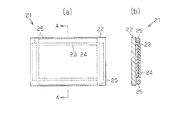
図6(a)に、ディスプレイとタッチパッドとが一体となったタッチ式入力装置21を、図6(b)に図6(a)のA−A線に沿った断面図をそれぞれ示す。同図6(a)、図6(b)に示すように、横長の長方形板状のガラス22の裏面の中央部には、長方形板状のITO電極(透明電極)からなる静電センサ23が固定され、更にその裏面には、映像を映し出すLCD(Liquid Crystal Display)24が一体となって固定されている。ガラス22の表面は、微小凹凸面とされている。LCD24によって映し出される映像は、静電センサ23及びガラス22を透過してユーザにより視認される。また、またガラス22の裏面には、静電センサ23及びLCD24を上下及び左右の四方から囲う態様で4つの圧電素子25が固定されている。これら、静電センサ23、LCD24、及び圧電素子25は図示しない制御回路に接続されている。このタッチ式入力装置21は、図1に示す上記第1の実施形態のディスプレイ11と同じ位置に設けられる。
FIG. 6A shows a touch-
ユーザのLCD24を見ながらの操作は、同時に自分の手元を見ながらの操作になる。すなわち、ユーザは、画面と手元との両方を見ながらの操作となるため、機能項目の選択や入力が行い易くなる。また、上記第1の実施形態と同様に、タッチ位置が低摩擦領域である旨検出されるときには、制御回路は圧電素子25を通じて、同ガラス22を高周波振動させる。これにより、ユーザは、指をスムーズに移動させることができる。また、ユーザの指の位置が機能項目の角部、すなわち高摩擦領域にある場合には、制御回路は、ガラス22を振動させない。これにより、ユーザは、指先の感覚の違いから、指が機能項目上にないことが分かる。例えば、タッチ位置が低摩擦領域から高摩擦領域へ変位する際には、摩擦抵抗が急激に増大する。低摩擦領域は、各機能項目に対応し、高摩擦領域は、機能項目から外れた領域であるので、ユーザは、指が機能項目に対応する領域に触れていないことを容易に認識することができる。また、ユーザは、触覚を通じて、機能項目に対応する低摩擦領域への移動が促される。こうして、より正確な機能項目の選択及び入力が行われる。
The user's operation while looking at the
以上詳述したように、本実施形態によれば、上記第1の実施形態の(1)及び(2)の効果に加えて、以下に示す効果が得られる。
(4)静電センサ23とLCD24とを一体とした。これにより、ユーザは、画面と手元との両方も視認しながらの操作となるため、機能項目の選択及び入力が容易かつ正確に行うことができる。
As described above in detail, according to the present embodiment, in addition to the effects (1) and (2) of the first embodiment, the following effects can be obtained.
(4) The
なお、上記実施形態は以下のように変更してもよい。
・上記各実施形態においては、圧電素子15(25)へ電力を供給するか否かの2段階で切り替えることにより、タッチパッド13(ガラス22)上の指をスライドさせやすくしたりスライドさせにくくしたりしたが、圧電素子15(25)へ電力を供給する場合に、その供給量を変動させてもよい。すなわち、タッチパッド13(ガラス22)を異なる周波数(振動速度)で振動させてもよい。こうすることで、同タッチパッド13(ガラス22)上の指のスライドのしにくさを多段階とすることができる。
In addition, you may change the said embodiment as follows.
In each of the above embodiments, the finger on the touch pad 13 (glass 22) can be easily slid or difficult to slide by switching in two stages whether or not power is supplied to the piezoelectric element 15 (25). However, when power is supplied to the piezoelectric element 15 (25), the supply amount may be varied. That is, the touch pad 13 (glass 22) may be vibrated at a different frequency (vibration speed). By doing so, the difficulty of sliding the finger on the touchpad 13 (glass 22) can be made in multiple stages.
・上記各実施形態では、ディスプレイ11に表示させた機能項目を4つとしたが、その数はこれに限らない。
・上記第1の実施形態では、タッチパッド13を指で操作するようにしたが、ユーザが摩擦抵抗の違いを認識できればよい。すなわち、手袋をした手などで操作するようにしてもよい。このようにしても、上記第1の実施形態の効果と同様の効果を得ることができる。
In each of the above embodiments, four function items are displayed on the
In the first embodiment, the
・上記第1の実施形態において、タッチパッド13の微小凹凸面をなくしてもよい。すなわち、平滑面であってもよい。また、操作面に採用する材質等で同操作面と指との間の摩擦抵抗を調整してもよい。
In the first embodiment, the fine uneven surface of the
・上記第1の実施形態において、感圧センサ14と圧電素子15との位置を入れ替えてもよい。
・上記第1の実施形態において、感圧センサ14は、タッチパッド13に触れた指の位置を検出できるように、圧電素子15は、タッチパッド13を振動させるようにそれぞれ設けられればよい。すなわち、タッチパッド13、感圧センサ14、及び圧電素子15は、重なって配置されていなくてもよい。
In the first embodiment, the positions of the pressure sensor 14 and the
In the first embodiment, the pressure sensor 14 may be provided so as to vibrate the
・上記第1の実施形態において、制御回路16は、車両の付帯機器の制御手段に指令を行ってもよい。すなわち、制御回路16は、ディスプレイシステム10を直接制御しなくともよい。
In the first embodiment, the
・上記各実施形態において、低摩擦領域と高摩擦領域とを逆にしてもよい。すなわち、機能項目と対応する位置を高摩擦領域に、機能項目の角部と対応する位置を低摩擦領域としてもよい。こうしても、ディスプレイ11を視認せずとも、指を機能項目に沿って動かしているか否かを認識することができる。
In each of the above embodiments, the low friction region and the high friction region may be reversed. That is, the position corresponding to the function item may be a high friction area, and the position corresponding to the corner of the function item may be a low friction area. Even in this way, it is possible to recognize whether or not the finger is moved along the function item without visually recognizing the
・上記各実施形態では、ディスプレイ11に表示させた機能項目は、格子状に配置されるようにしたが、格子状に配置されていなくてもよい。例えば、環状や山形状に配置するようにする。このようにしても、上記各実施形態の(1)、(3)、(4)と同様の効果を得ることができる。
In each of the above embodiments, the function items displayed on the
・上記各実施形態において、このディスプレイシステム10は、車両以外に適用してもよい。例えば、ノートパソコン等に設けられる操作パッド等に適用してもよい。
次に、上記実施形態及び別例から把握できる技術的思想について以下に追記する。
In each of the above embodiments, the
Next, the technical idea that can be grasped from the above embodiment and other examples will be described below.
(イ)請求項1〜4のいずれか一項に記載のタッチ式入力装置において、前記ディスプレイと前記タッチパッドとが離れて配置されてなるタッチ式入力装置。
同構成によれば、例えば、ディスプレイを視認しやすい位置に配置し、タッチパッドを操作しやすい手元の位置に配置することができる。これにより、ユーザは、ディスプレイを視認したまま、指先の操作を容易に行うことができるので、同ディスプレイに表示されている機能項目の選択及び入力が容易になる。
(A) The touch input device according to any one of claims 1 to 4, wherein the display and the touch pad are arranged apart from each other.
According to this configuration, for example, the display can be placed at a position where it can be easily seen, and the touchpad can be placed at a position where it can be easily operated. Accordingly, the user can easily operate the fingertip while visually recognizing the display, so that the function item displayed on the display can be easily selected and input.
(ロ)請求項1〜4のいずれか一項に記載のタッチ式入力装置において、前記ディスプレイと前記タッチパッドとが一体に設けられてなるタッチ式入力装置。
同構成によれば、ユーザは、ディスプレイを視認することがタッチパッドを視認することにも繋がる。すなわち、ユーザは、ディスプレイとタッチパッドとを視認しながら指先の操作を行うことになるので、同ディスプレイに表示されている機能項目の選択及び入力をより正確に行うことができる。
(B) The touch input device according to any one of claims 1 to 4, wherein the display and the touch pad are integrally provided.
According to this configuration, the user can visually recognize the display and also can visually recognize the touch pad. That is, since the user performs the fingertip operation while visually recognizing the display and the touch pad, the function item displayed on the display can be selected and input more accurately.
(ハ)車両に搭載されることを特徴とする請求項2〜4のうちいずれか一項に記載のタッチ式入力装置。
同構成によれば、車両に設けられる多様な付帯機器を動作させるための機能項目をディスプレイに表示させることにより、ユーザは、タッチパッドの操作のみで、車両に設けられた付帯機器を動作させることができる。
(C) The touch input device according to any one of
According to this configuration, by displaying function items for operating various accessory devices provided in the vehicle on the display, the user can operate the accessory devices provided in the vehicle only by operating the touch pad. Can do.
1…ダッシュボード、2…センターコンソール、3…シフトレバー、10…ディスプレイシステム、11…ディスプレイ、12,21…タッチ式入力装置、13…タッチパッド、14…感圧センサ、15,25…圧電素子、16…制御回路、17…駆動回路、22…ガラス、23…静電センサ、24…LCD。 DESCRIPTION OF SYMBOLS 1 ... Dashboard, 2 ... Center console, 3 ... Shift lever, 10 ... Display system, 11 ... Display, 12, 21 ... Touch-type input device, 13 ... Touch pad, 14 ... Pressure sensor, 15, 25 ... Piezoelectric element , 16 ... control circuit, 17 ... drive circuit, 22 ... glass, 23 ... electrostatic sensor, 24 ... LCD.
Claims (2)
前記タッチパッドには、前記操作面に対するタッチ位置を検出するセンサと、給電されることにより振動する圧電素子とを設け、
前記制御手段は、前記ディスプレイに前記複数の機能項目を格子状となるように設定し、前記タッチパッド上の前記機能項目の表示位置及び隣接する機能項目同士が接続される位置に対応する領域を第1の領域と設定し、前記タッチパッド上の前記第1の領域に該当しない領域を第2の領域と設定し、前記タッチ位置が前記第1の領域に位置する場合には前記圧電素子への給電を行い、前記タッチ位置が前記第2の領域に位置する場合には前記圧電素子への給電を行わないことで、前記タッチパッド上の指を前記機能項目に対応する位置に案内するタッチ式入力装置。 A control unit configured to display a plurality of function items on a display according to input information; and a touch pad having an operation surface exposed to the outside. The control unit displays the display on the display based on a touch operation on the operation surface. In a touch input device for selecting a function item to be performed and determining the selection,
The touch pad is provided with a sensor that detects a touch position on the operation surface and a piezoelectric element that vibrates when supplied with power,
The control means sets the plurality of function items on the display so as to form a grid, and displays an area corresponding to a display position of the function items on the touch pad and a position where adjacent function items are connected to each other. set the first region, a region not corresponding to the first region on the touch pad to set the second region, the if the touch position is located in the first area to the piezoelectric element perform feeding, wherein when the touch position is located at the second region by not performing the power supply to the piezoelectric element, a touch to guide the finger on the touch pad in a position corresponding to the function item Expression input device.
前記タッチパッドの操作面は、無数の微小凹凸が形成された粗面であるタッチ式入力装置。 The touch input device according to claim 1 ,
The touch-pad input device is an operation surface of the touch pad that is a rough surface on which innumerable minute irregularities are formed.
Priority Applications (1)
| Application Number | Priority Date | Filing Date | Title |
|---|---|---|---|
| JP2010215178A JP5778904B2 (en) | 2010-09-27 | 2010-09-27 | Touch input device |
Applications Claiming Priority (1)
| Application Number | Priority Date | Filing Date | Title |
|---|---|---|---|
| JP2010215178A JP5778904B2 (en) | 2010-09-27 | 2010-09-27 | Touch input device |
Publications (2)
| Publication Number | Publication Date |
|---|---|
| JP2012069048A JP2012069048A (en) | 2012-04-05 |
| JP5778904B2 true JP5778904B2 (en) | 2015-09-16 |
Family
ID=46166203
Family Applications (1)
| Application Number | Title | Priority Date | Filing Date |
|---|---|---|---|
| JP2010215178A Expired - Fee Related JP5778904B2 (en) | 2010-09-27 | 2010-09-27 | Touch input device |
Country Status (1)
| Country | Link |
|---|---|
| JP (1) | JP5778904B2 (en) |
Families Citing this family (8)
| Publication number | Priority date | Publication date | Assignee | Title |
|---|---|---|---|---|
| JP6024873B2 (en) * | 2012-05-21 | 2016-11-16 | Hoya株式会社 | Cover glass for trackpad and method for manufacturing the same |
| JP2014071464A (en) * | 2012-09-27 | 2014-04-21 | Tokai Rika Co Ltd | Touch type input device |
| CN103019611A (en) * | 2012-12-31 | 2013-04-03 | 传聚互动(北京)科技有限公司 | Screen touch method and device |
| KR102128394B1 (en) * | 2013-09-11 | 2020-07-01 | 삼성디스플레이 주식회사 | Touch sensible display device |
| KR101551030B1 (en) | 2013-12-26 | 2015-09-07 | 현대자동차주식회사 | Input pad and controlling method thereof |
| KR101628462B1 (en) | 2014-06-24 | 2016-06-08 | 현대자동차주식회사 | System for auditory user interface |
| WO2016038676A1 (en) * | 2014-09-09 | 2016-03-17 | 三菱電機株式会社 | Tactile sensation control system and tactile sensation control method |
| JP6693641B2 (en) * | 2015-03-26 | 2020-05-13 | 天馬微電子有限公司 | Tactile presentation device, electronic device, and driving method of tactile presentation device |
Family Cites Families (6)
| Publication number | Priority date | Publication date | Assignee | Title |
|---|---|---|---|---|
| JP2000076005A (en) * | 1998-09-02 | 2000-03-14 | Ricoh Co Ltd | Touch pad |
| JP2000194427A (en) * | 1998-12-25 | 2000-07-14 | Tokai Rika Co Ltd | Touch operation input device |
| JP2005258666A (en) * | 2004-03-10 | 2005-09-22 | Sony Corp | Input device, electronic device, and method for inputting touch to electronic device as feedback |
| JP2006039837A (en) * | 2004-07-26 | 2006-02-09 | Smk Corp | Touch panel input device |
| WO2010105001A1 (en) * | 2009-03-12 | 2010-09-16 | Immersion Corporation | Systems and methods for providing features in a friction display |
| JP2010102741A (en) * | 2010-02-08 | 2010-05-06 | Toshiba Corp | Electronic device |
-
2010
- 2010-09-27 JP JP2010215178A patent/JP5778904B2/en not_active Expired - Fee Related
Also Published As
| Publication number | Publication date |
|---|---|
| JP2012069048A (en) | 2012-04-05 |
Similar Documents
| Publication | Publication Date | Title |
|---|---|---|
| JP5778904B2 (en) | Touch input device | |
| JP5409657B2 (en) | Image display device | |
| JP2014102660A (en) | Manipulation assistance system, manipulation assistance method, and computer program | |
| EP3422156B1 (en) | Control unit for vehicle and control method for the same | |
| JP5644962B2 (en) | Operating device | |
| JP6147656B2 (en) | Input device | |
| JP2008197934A (en) | Operator determining method | |
| KR20100074695A (en) | Touch sensitive interface device | |
| US11144193B2 (en) | Input device and input method | |
| JP2014102656A (en) | Manipulation assistance system, manipulation assistance method, and computer program | |
| JP2015228118A (en) | Operating device | |
| CN109564469B (en) | Display operation device | |
| WO2014049794A1 (en) | Electronic device | |
| JP5946806B2 (en) | Touch switch module | |
| JP2018136616A (en) | Display operation system | |
| KR101682527B1 (en) | touch keypad combined mouse using thin type haptic module | |
| JP2013073365A (en) | Information processing device | |
| JP2013033343A (en) | Operation device for vehicle | |
| KR101422060B1 (en) | Information display apparatus and method for vehicle using touch-pad, and information input module thereof | |
| JP2015118424A (en) | Information processing device | |
| JP2014100998A (en) | Operation support system, operation support method, and computer program | |
| JP7529380B2 (en) | Vehicle operation control device | |
| JP2014102658A (en) | Operation support system, operation support method, and computer program | |
| JP2014102657A (en) | Manipulation assistance system, manipulation assistance method, and computer program | |
| JP2014102655A (en) | Manipulation assistance system, manipulation assistance method, and computer program |
Legal Events
| Date | Code | Title | Description |
|---|---|---|---|
| A621 | Written request for application examination |
Free format text: JAPANESE INTERMEDIATE CODE: A621 Effective date: 20130418 |
|
| A977 | Report on retrieval |
Free format text: JAPANESE INTERMEDIATE CODE: A971007 Effective date: 20131127 |
|
| A131 | Notification of reasons for refusal |
Free format text: JAPANESE INTERMEDIATE CODE: A131 Effective date: 20131203 |
|
| A521 | Request for written amendment filed |
Free format text: JAPANESE INTERMEDIATE CODE: A523 Effective date: 20140117 |
|
| A02 | Decision of refusal |
Free format text: JAPANESE INTERMEDIATE CODE: A02 Effective date: 20140311 |
|
| A521 | Request for written amendment filed |
Free format text: JAPANESE INTERMEDIATE CODE: A523 Effective date: 20140526 |
|
| A911 | Transfer to examiner for re-examination before appeal (zenchi) |
Free format text: JAPANESE INTERMEDIATE CODE: A911 Effective date: 20140603 |
|
| A912 | Re-examination (zenchi) completed and case transferred to appeal board |
Free format text: JAPANESE INTERMEDIATE CODE: A912 Effective date: 20140905 |
|
| A521 | Request for written amendment filed |
Free format text: JAPANESE INTERMEDIATE CODE: A523 Effective date: 20150527 |
|
| A61 | First payment of annual fees (during grant procedure) |
Free format text: JAPANESE INTERMEDIATE CODE: A61 Effective date: 20150710 |
|
| R150 | Certificate of patent or registration of utility model |
Ref document number: 5778904 Country of ref document: JP Free format text: JAPANESE INTERMEDIATE CODE: R150 |
|
| LAPS | Cancellation because of no payment of annual fees |