JP2014100998A - Operation support system, operation support method, and computer program - Google Patents

Operation support system, operation support method, and computer program Download PDF

Info

Publication number
JP2014100998A
JP2014100998A JP2012253686A JP2012253686A JP2014100998A JP 2014100998 A JP2014100998 A JP 2014100998A JP 2012253686 A JP2012253686 A JP 2012253686A JP 2012253686 A JP2012253686 A JP 2012253686A JP 2014100998 A JP2014100998 A JP 2014100998A
Authority
JP
Japan
Prior art keywords
input device
vehicle
operation input
state
operation surface
Prior art date
Legal status (The legal status is an assumption and is not a legal conclusion. Google has not performed a legal analysis and makes no representation as to the accuracy of the status listed.)
Pending
Application number
JP2012253686A
Other languages
Japanese (ja)
Inventor
Shinichi Kubota
真一 窪田
Current Assignee (The listed assignees may be inaccurate. Google has not performed a legal analysis and makes no representation or warranty as to the accuracy of the list.)
Aisin AW Co Ltd
Original Assignee
Aisin AW Co Ltd
Priority date (The priority date is an assumption and is not a legal conclusion. Google has not performed a legal analysis and makes no representation as to the accuracy of the date listed.)
Filing date
Publication date
Application filed by Aisin AW Co Ltd filed Critical Aisin AW Co Ltd
Priority to JP2012253686A priority Critical patent/JP2014100998A/en
Publication of JP2014100998A publication Critical patent/JP2014100998A/en
Pending legal-status Critical Current

Links

Images

Abstract

PROBLEM TO BE SOLVED: To provide an operation support system, an operation support method, and a computer program which can make a user who gets on a vehicle for the first time recognize presence of an operation surface.SOLUTION: An operation support system displays a plurality of menu icons 41 as operation objects on a windshield 36. The operation support system selects and operates either one of the menu icon 41 from among the displayed menu icons 41 based on a touch operation received by a left operation input device 2 and a touch operation received by a right operation input device 3. On the other hand, when an operation to simultaneously touch operation surfaces of touch pads 11 of the left operation input device 2 and the right operation input device 3 is received, the operation support system performs special control for vehicle equipment such as ON control of an engine (S32, S36, S38-S40).

Description

本発明は、タッチ操作による車両内の機器の操作を支援する操作支援システム、操作支援方法及びコンピュータプログラムに関する。   The present invention relates to an operation support system, an operation support method, and a computer program that support operation of equipment in a vehicle by touch operation.

従来より、パーソナルコンピュータ、ATM、券売機、ナビゲーション装置、スマートフォン等の機器に対してユーザが操作を行う際に、機器に対するユーザの操作を受け付ける手段として、様々なマンマシンインタフェースが用いられている。特に、近年、マンマシンインタフェースの一つとして、ユーザのタッチ操作を受け付ける操作面を設け、該操作面に対するユーザのタッチ操作(例えば、タッチオンする操作、タッチオフする操作、ドラッグ操作、フリック操作等)をユーザの操作として検出する操作機器が良く用いられる。このような操作機器としては、タッチパッド、タッチパネル、タブレット等(以下、タッチパッド等という)があり、ユーザに直感的で分かり易い操作を行わせることが可能となる。   Conventionally, when a user performs an operation on a device such as a personal computer, an ATM, a ticket vending machine, a navigation device, or a smartphone, various man-machine interfaces have been used as means for receiving the user's operation on the device. Particularly, in recent years, as one of the man-machine interfaces, an operation surface that accepts a user's touch operation is provided, and a user's touch operation on the operation surface (for example, a touch-on operation, a touch-off operation, a drag operation, a flick operation, etc.) is performed. An operation device that is detected as a user operation is often used. Examples of such an operation device include a touch pad, a touch panel, a tablet, and the like (hereinafter referred to as a touch pad), which allows a user to perform an intuitive and easy-to-understand operation.

ここで、上記タッチパッド等をユーザが操作する場合の操作態様として、ユーザがタッチパッド等を視認せずに操作を行う場合がある。具体的には、他の作業を行いながら、タッチパッド等の操作を行う場合であり、例えば、車両の運転操作をしながらタッチパッド等の操作を行う場合がある。例えば、特開2012−177999号公報には、車両のハンドルに対して左右2箇所に円形状のタッチパッドを設け、タッチパッドに対する指のタッチ操作と、ディスプレイに表示される表示内容とを用いて、ナビゲーション装置やオーディオ機器等の車載器の操作を行う技術について記載されている。   Here, as an operation mode when the user operates the touch pad or the like, the user may perform an operation without visually recognizing the touch pad or the like. Specifically, it is a case where an operation of a touch pad or the like is performed while performing other work, for example, an operation of a touch pad or the like may be performed while a driving operation of the vehicle is performed. For example, in JP 2012-177999 A, circular touchpads are provided at two positions on the left and right of a vehicle handle, and finger touch operations on the touchpad and display contents displayed on the display are used. In addition, a technique for operating a vehicle-mounted device such as a navigation device or an audio device is described.

特開2012−177999号公報(第10頁−第11頁、図1)JP 2012-177999 A (page 10 to page 11, FIG. 1)

ここで、上記特許文献1に記載の技術では、左側に配置されたタッチパッドに対するタッチ操作と右側に配置されたタッチパッドに対するタッチ操作の組み合わせによって、車載器に対して様々な操作(例えば地図画像の縮尺変更等)を行うことが記載されている。しかしながら、複数のタッチパッドへのタッチ操作の組み合わせにより操作を行うことによって、複雑な操作指示が実現できる一方、操作内容が複雑になる問題があった。また、タッチパッドがハンドルに一体化して設けられるので、レンタカー等を借りて乗車したユーザはタッチパッドの存在に気付かない虞がある。   Here, in the technique described in Patent Document 1, various operations (for example, map images) are performed on the vehicle-mounted device by combining the touch operation on the touch pad arranged on the left side and the touch operation on the touch pad arranged on the right side. To change the scale, etc.). However, a complicated operation instruction can be realized by performing an operation by a combination of touch operations on a plurality of touch pads, but the operation contents are complicated. In addition, since the touch pad is provided integrally with the handle, a user who rents a rental car or the like may not notice the presence of the touch pad.

本発明は前記従来における問題点を解消するためになされたものであり、ハンドルの異なる箇所に設置された2つの操作面に対して同時に触れるという簡易なユーザの操作によって、車両機器に対する各種制御を行うことを可能となるとともに、車両に始めて乗車するユーザに対しても操作面の存在を認識させることを可能にした操作支援システム、操作支援方法及びコンピュータプログラムを提供することを目的とする。   The present invention has been made to solve the above-described conventional problems, and various controls for vehicle equipment can be performed by a simple user operation of simultaneously touching two operation surfaces installed at different positions of a handle. It is an object of the present invention to provide an operation support system, an operation support method, and a computer program that can be performed and also allow a user who first gets on a vehicle to recognize the presence of an operation surface.

前記目的を達成するため本願の請求項1に係る操作支援システム(1)は、車両のハンドル(5)の異なる箇所に夫々設けられ、操作面(11)を介して前記ユーザの操作を受け付ける第1操作入力装置(2)及び第2操作入力装置(3)と、前記第1操作入力装置及び前記第2操作入力装置により操作される操作対象物(41)を表示する表示機器(4)と、を備えた操作支援システムにおいて、複数の前記操作対象物を前記表示機器に表示する操作対象物表示手段(31)と、前記第1操作入力装置の操作面と前記第2操作入力装置の操作面とに同時に触れる操作を受け付けた場合に、前記表示機器を含む車両機器のいずれかを制御する車両制御手段(31)と、を有することを特徴とする。
尚、「操作面に触れる」とは、実際にユーザが操作面に接触する場合に加えて、静電容量方式ではユーザが操作面に接触していなくても静電容量が変化した場合には触れたとみなす。
また、「同時に触れる」とは厳密に同一時刻に触れることに加えて、触れた時刻に許容範囲内の差分が有る場合も含む。
In order to achieve the above object, the operation support system (1) according to claim 1 of the present application is provided at each of different places of the vehicle handle (5) and receives the user's operation via the operation surface (11). A first operation input device (2) and a second operation input device (3); and a display device (4) for displaying an operation object (41) operated by the first operation input device and the second operation input device; The operation object display means (31) for displaying a plurality of the operation objects on the display device, the operation surface of the first operation input device, and the operation of the second operation input device Vehicle control means (31) for controlling any of the vehicle devices including the display device when an operation for simultaneously touching the surface is received.
In addition to the case where the user actually touches the operation surface, “touch the operation surface” means that when the capacitance changes even if the user does not touch the operation surface in the capacitance method. It is considered touched.
Further, “touching at the same time” includes not only strictly touching the same time but also a case where the touched time has a difference within an allowable range.

また、請求項2に係る操作支援システム(1)は、請求項1に記載の操作支援システムであって、前記車両制御手段(31)は、前記車両機器の制御状態と、前記第1操作入力装置の操作面と前記第2操作入力装置の操作面とに同時に触れる操作とに基づいて、前記車両機器の制御状態を制御することを特徴とする。   An operation support system (1) according to claim 2 is the operation support system according to claim 1, wherein the vehicle control means (31) includes a control state of the vehicle device and the first operation input. The control state of the vehicle device is controlled based on an operation that simultaneously touches the operation surface of the device and the operation surface of the second operation input device.

また、請求項3に係る操作支援システム(1)は、請求項1又は請求項2に記載の操作支援システムであって、前記第1操作入力装置(2)の操作面(11)は前記ハンドル(5)の左側のスポーク部分に配置され、前記第2操作入力装置(3)の操作面は前記ハンドルの右側のスポーク部分に配置されることを特徴とする。   An operation support system (1) according to claim 3 is the operation support system according to claim 1 or 2, wherein the operation surface (11) of the first operation input device (2) is the handle. (5) It is arrange | positioned at the left spoke part, The operation surface of the said 2nd operation input device (3) is arrange | positioned at the spoke part on the right side of the said handle | steering-wheel.

また、請求項4に係る操作支援システム(1)は、請求項1乃至請求項3のいずれかに記載の操作支援システムであって、前記車両機器は前記車両の駆動源を含み、前記車両制御手段は、前記第1操作入力装置(2)の操作面(11)と前記第2操作入力装置(3)の操作面とに同時に触れる操作を受け付けた場合に、前記駆動源をオン又はオフに制御することを特徴とする。
尚、車両の駆動源としては、例えばエンジンやモータがある。
An operation support system (1) according to claim 4 is the operation support system according to any one of claims 1 to 3, wherein the vehicle device includes a drive source of the vehicle, and the vehicle control The means turns the drive source on or off when an operation of simultaneously touching the operation surface (11) of the first operation input device (2) and the operation surface of the second operation input device (3) is received. It is characterized by controlling.
In addition, there exist an engine and a motor as a drive source of a vehicle, for example.

また、請求項5に係る操作支援システム(1)は、請求項4に記載の操作支援システムであって、前記車両制御手段(31)は、前記車両機器の制御状態として前記車両の駆動源がオフ状態であって、且つ前記第1操作入力装置(2)の操作面と前記第2操作入力装置(3)の操作面とに同時に触れる操作を受け付けた場合に、前記駆動源をオフ状態からオン状態に制御することを特徴とする。   Further, the operation support system (1) according to claim 5 is the operation support system according to claim 4, wherein the vehicle control means (31) has a drive source of the vehicle as a control state of the vehicle equipment. In the off state and when an operation for simultaneously touching the operation surface of the first operation input device (2) and the operation surface of the second operation input device (3) is received, the drive source is changed from the off state. It is characterized by controlling to an on state.

また、請求項6に係る操作支援システム(1)は、請求項4又は請求項5に記載の操作支援システムであって、前記第1操作入力装置(2)の操作面と前記第2操作入力装置(3)の操作面とに同時に触れる操作を受け付けた場合に、その後に両方の前記操作面において同時に触れる状態を継続した時間を検出するタッチ時間検出手段を有し、前記車両制御手段(31)は、前記車両機器の制御状態として前記車両の駆動源がオン状態であって、前記第1操作入力装置の操作面と前記第2操作入力装置の操作面とに同時に触れる操作を受け付けた場合で、且つ前記タッチ時間検出手段によって検出された時間が閾値以上である場合に、前記駆動源をオン状態からオフ状態に制御することを特徴とする。   An operation support system (1) according to claim 6 is the operation support system according to claim 4 or 5, wherein the operation surface of the first operation input device (2) and the second operation input A touch time detecting means for detecting a time during which a state in which the operation surface of the device (3) is touched at the same time is continuously touched on both of the operation faces thereafter; and the vehicle control means (31 ) Is a case where the driving source of the vehicle is on as the control state of the vehicle device and an operation of simultaneously touching the operation surface of the first operation input device and the operation surface of the second operation input device is received. And when the time detected by the touch time detecting means is greater than or equal to a threshold value, the drive source is controlled from an on state to an off state.

また、請求項7に係る操作支援システム(1)は、請求項4乃至請求項6のいずれかに記載の操作支援システムであって、前記第1操作入力装置(2)の操作面と前記第2操作入力装置(3)の操作面とに同時に触れる操作を受け付けた否かを判定する同時操作判定手段(31)を有し、前記同時操作判定手段は、所定の許容範囲時間内に前記第1操作入力装置の操作面と前記第2操作入力装置の操作面とにそれぞれ触れる操作を受け付けた場合に、前記第1操作入力装置の操作面と前記第2操作入力装置の操作面とに同時に触れる操作を受け付けたと判定し、前記許容範囲時間は、前記車両機器の制御状態として前記車両の駆動源がオン状態である場合に比べて前記車両の駆動源がオフ状態である場合に短く設定することを特徴とする。   An operation support system (1) according to claim 7 is the operation support system according to any one of claims 4 to 6, wherein the operation surface of the first operation input device (2) and the first Two-operation input device (3) having simultaneous operation determining means (31) for determining whether or not an operation touching the operation surface at the same time has been received, wherein the simultaneous operation determining means is within the predetermined allowable range time. When an operation touching the operation surface of one operation input device and the operation surface of the second operation input device is received, the operation surface of the first operation input device and the operation surface of the second operation input device are simultaneously received. It is determined that a touch operation has been received, and the allowable range time is set to be shorter when the vehicle drive source is in an off state as compared to when the vehicle drive source is in an on state as a control state of the vehicle device. It is characterized by that.

また、請求項8に係る操作支援システム(1)は、請求項4乃至請求項7のいずれかに記載の操作支援システムであって、前記車両制御手段(31)は、前記車両機器の制御状態として前記車両の駆動源がオン状態であって、前記車両のパーキングブレーキが作動している状態と判定した場合で、且つ前記第1操作入力装置(2)の操作面と前記第2操作入力装置(3)の操作面とに同時に触れる操作を受け付けた場合に、前記駆動源をオン状態からオフ状態に制御することを特徴とする。   An operation support system (1) according to claim 8 is the operation support system according to any one of claims 4 to 7, wherein the vehicle control means (31) is a control state of the vehicle equipment. And when the driving source of the vehicle is on and it is determined that the parking brake of the vehicle is operating, and the operation surface of the first operation input device (2) and the second operation input device (3) When the operation which touches the operation surface simultaneously is received, the said drive source is controlled from an ON state to an OFF state, It is characterized by the above-mentioned.

また、請求項9に係る操作支援システム(1)は、請求項1乃至請求項3のいずれかに記載の操作支援システムであって、前記車両制御手段(31)は、前記車両機器の制御状態として前記表示機器(4)の表示画面の電源がオフ状態であって、且つ前記第1操作入力装置の操作面と前記第2操作入力装置の操作面とに同時に触れる操作を受け付けた場合に、前記表示機器において前記操作対象物の選択画面(40)を表示するように前記表示機器を制御することを特徴とする。   An operation support system (1) according to claim 9 is the operation support system according to any one of claims 1 to 3, wherein the vehicle control means (31) is a control state of the vehicle equipment. When the power of the display screen of the display device (4) is in an off state and an operation of simultaneously touching the operation surface of the first operation input device and the operation surface of the second operation input device is received, The display device is controlled to display the selection screen (40) for the operation object on the display device.

また、請求項10に係る操作支援システム(1)は、請求項1乃至請求項3、請求項9のいずれかに記載の操作支援システムであって、前記車両制御手段(31)は、前記車両機器の制御状態として前記表示機器(4)の表示画面の電源がオン状態であって、且つ前記第1操作入力装置(2)の操作面と前記第2操作入力装置(3)の操作面とに同時に触れる操作を受け付けた場合に、前記表示機器の電源をオン状態からオフ状態に制御することを特徴とする。   An operation support system (1) according to claim 10 is the operation support system according to any one of claims 1 to 3 and 9, wherein the vehicle control means (31) is the vehicle. The display screen of the display device (4) is turned on as the device control state, and the operation surface of the first operation input device (2) and the operation surface of the second operation input device (3) When an operation for simultaneously touching is received, the power of the display device is controlled from an on state to an off state.

また、請求項11に係る操作支援システム(1)は、請求項1乃至請求項3のいずれかに記載の操作支援システムであって、前記第1操作入力装置(2)の操作面と前記第2操作入力装置(3)の操作面とに同時に触れる操作を受け付けた場合に、その後に両方の前記操作面において同時に触れる状態を継続した時間を検出するタッチ時間検出手段(31)を有し、前記車両制御手段(31)は、前記タッチ時間検出手段によって検出された時間によって異なる制御を行うことを特徴とする。   An operation support system (1) according to an eleventh aspect is the operation support system according to any one of the first to third aspects, wherein the operation surface of the first operation input device (2) and the first 2 When the operation touching the operation surface of the operation input device (3) is accepted at the same time, it has a touch time detecting means (31) for detecting the time during which the operation state is continuously touched on both the operation surfaces thereafter. The vehicle control means (31) performs different control depending on the time detected by the touch time detection means.

また、請求項12に係る操作支援システム(1)は、請求項11に記載の操作支援システムであって、前記車両制御手段(31)は、前記タッチ時間検出手段(31)によって検出された時間が閾値未満である場合には、前記表示機器(4)において前記操作対象物の選択画面(40)を表示又は電源をオフするように前記表示機器を制御し、前記タッチ時間検出手段によって検出された時間が閾値以上である場合には、前記車両のエンジンをオフに制御することを特徴とする。   The operation support system (1) according to claim 12 is the operation support system according to claim 11, wherein the vehicle control means (31) is a time detected by the touch time detection means (31). Is less than the threshold value, the display device (4) controls the display device to display the operation object selection screen (40) or to turn off the power, and is detected by the touch time detection means. If the elapsed time is greater than or equal to a threshold value, the vehicle engine is controlled to be turned off.

また、請求項13に係る操作支援方法は、車両のハンドル(5)の異なる箇所に夫々設けられ、操作面(11)を介して前記ユーザの操作を受け付ける第1操作入力装置(2)及び第2操作入力装置(3)と、前記第1操作入力装置及び前記第2操作入力装置により操作される操作対象物(41)を表示する表示機器(4)と、を備えた操作支援システムによる操作支援方法において、複数の前記操作対象物を前記表示機器に表示する操作対象物表示ステップと、前記第1操作入力装置の操作面と前記第2操作入力装置の操作面とに同時に触れる操作を受け付けた場合に、前記表示機器を含む車両機器のいずれかを制御する車両制御ステップと、を有することを特徴とする操作支援方法。   According to a thirteenth aspect of the present invention, there is provided an operation support method according to a first operation input device (2) and a first operation input device (2), which are provided at different locations on the vehicle handle (5) and receive the user's operation via the operation surface (11). Operation by an operation support system including a two-operation input device (3) and a display device (4) that displays an operation object (41) operated by the first operation input device and the second operation input device In the support method, an operation object display step for displaying the plurality of operation objects on the display device, and an operation of simultaneously touching the operation surface of the first operation input device and the operation surface of the second operation input device are received. And a vehicle control step for controlling any of the vehicle devices including the display device.

更に、請求項14に係るコンピュータプログラムは、車両のハンドル(5)の異なる箇所に夫々設けられ、操作面(11)を介して前記ユーザの操作を受け付ける第1操作入力装置(2)及び第2操作入力装置(3)と、前記第1操作入力装置及び前記第2操作入力装置により操作される操作対象物(41)を表示する表示機器(4)と、を備えた操作支援システムにおいて実行されるコンピュータプログラムにおいて、複数の前記操作対象物を前記表示機器に表示する操作対象物表示機能と、前記第1操作入力装置の操作面と前記第2操作入力装置の操作面とに同時に触れる操作を受け付けた場合に、前記表示機器を含む車両機器のいずれかを制御する車両制御機能と、を実行させることを特徴とする。   Furthermore, the computer program according to claim 14 is provided at different locations of the vehicle handle (5), respectively, and the first operation input device (2) and the second operation input device (2) for receiving the user's operation via the operation surface (11). It is executed in an operation support system comprising an operation input device (3) and a display device (4) for displaying an operation object (41) operated by the first operation input device and the second operation input device. An operation object display function for displaying a plurality of the operation objects on the display device, and an operation of simultaneously touching an operation surface of the first operation input device and an operation surface of the second operation input device. When received, a vehicle control function for controlling any of the vehicle devices including the display device is executed.

前記構成を有する請求項1に記載の操作支援システムによれば、表示機器に表示された複数の操作対象物からいずれかの操作対象物を選択させる操作をユーザに行わせる場合において、操作対象物が多数ある場合であってもハンドルの異なる箇所に設置された2つの操作面への操作を組み合わせることによってユーザの意図する操作対象物を正確に選択させつつ、2つの操作面に対して同時に触れるという簡易なユーザの操作によって、車両機器に対する各種制御を行うことが可能となる。また、2つの操作面を触れさせることによって、車両に始めて乗車するユーザに対しても操作面の存在を認識させることが可能となる。   According to the operation support system of claim 1 having the above-described configuration, when the user performs an operation of selecting any one of the operation objects from the plurality of operation objects displayed on the display device, the operation object Even when there are a large number of touch screens, the user can touch the two operation surfaces at the same time while accurately selecting the operation target intended by the user by combining the operations on the two operation surfaces installed at different positions of the handle. Various controls on the vehicle equipment can be performed by a simple user operation. Further, by touching the two operation surfaces, it is possible to make the user who first gets on the vehicle recognize the presence of the operation surfaces.

また、請求項2に記載の操作支援システムによれば、車両機器の制御状態と、第1操作入力装置の操作面と第2操作入力装置の操作面とに同時に触れる操作とに基づいて、車両機器の制御状態を制御するので、現在の車両機器の制御状態に応じた適切な制御を行うことが可能となる。   According to the operation support system of the second aspect, the vehicle is controlled based on the control state of the vehicle equipment and the operation of simultaneously touching the operation surface of the first operation input device and the operation surface of the second operation input device. Since the control state of the device is controlled, appropriate control according to the current control state of the vehicle device can be performed.

また、請求項3に記載の操作支援システムによれば、第1操作入力装置の操作面はハンドルの左側のスポーク部分に配置され、第2操作入力装置の操作面はハンドルの右側のスポーク部分に配置されるので、車両を運転するユーザは最小限の手の動きによって第1操作入力装置及び第2操作入力装置を操作することが可能となる。   According to the operation support system of the third aspect, the operation surface of the first operation input device is disposed on the left spoke portion of the handle, and the operation surface of the second operation input device is disposed on the right spoke portion of the handle. Therefore, the user who drives the vehicle can operate the first operation input device and the second operation input device with a minimum of hand movement.

また、請求項4に記載の操作支援システムによれば、第1操作入力装置の操作面と第2操作入力装置の操作面とに同時に触れる操作を受け付けた場合に、駆動源をオン又はオフに制御するので、第1操作入力装置と第2操作入力装置を用いた簡易な操作によって車両の駆動源のオン制御又はオフ制御が可能となる。また、運転開始時に、2つの操作面を触れさせる操作をユーザに課すことによって、車両に始めて乗車するユーザに対しても操作面の存在を確実に認識させることが可能となる。   According to the operation support system of the fourth aspect, when an operation of simultaneously touching the operation surface of the first operation input device and the operation surface of the second operation input device is received, the drive source is turned on or off. Since the control is performed, the vehicle drive source can be turned on or off by a simple operation using the first operation input device and the second operation input device. Further, by imposing on the user an operation for touching the two operation surfaces at the start of driving, it is possible for the user who gets on the vehicle for the first time to reliably recognize the presence of the operation surface.

また、請求項5に記載の操作支援システムによれば、車両の駆動源がオフ状態である場合に、第1操作入力装置と第2操作入力装置を用いた簡易な操作によって車両の駆動源をオンすることが可能となる。   According to the operation support system of the fifth aspect, when the drive source of the vehicle is in the off state, the drive source of the vehicle is set by a simple operation using the first operation input device and the second operation input device. It can be turned on.

また、請求項6に記載の操作支援システムによれば、車両の駆動源がオン状態である場合に、第1操作入力装置と第2操作入力装置を用いた簡易な操作によって車両の駆動源をオフすることが可能となる。また、両方の操作面において同時に触れる状態を継続していることを条件とするので、車両の走行中に誤って駆動源がオフされることを防止することが可能となる。   According to the operation support system of the sixth aspect, when the vehicle drive source is in the ON state, the vehicle drive source is set by a simple operation using the first operation input device and the second operation input device. It can be turned off. In addition, since it is a condition that the state where both operation surfaces are simultaneously touched is maintained, it is possible to prevent the drive source from being accidentally turned off while the vehicle is traveling.

また、請求項7に記載の操作支援システムによれば、第1操作入力装置の操作面と第2操作入力装置の操作面とに同時に触れる操作を受け付けたか否かの判定を行う際の許容範囲時間を、車両の駆動源がオン状態である場合に比べて車両の駆動源がオフ状態である場合に短く設定するので、誤操作が行われた際のリスクを考慮して適切な許容範囲時間を設定することが可能となる。   According to the operation support system of the seventh aspect, an allowable range for determining whether or not an operation of simultaneously touching the operation surface of the first operation input device and the operation surface of the second operation input device is accepted. Since the time is set to be shorter when the vehicle drive source is off compared to when the vehicle drive source is on, an appropriate tolerance time is set in consideration of the risk of erroneous operation. It becomes possible to set.

また、請求項8に記載の操作支援システムによれば、車両のパーキングブレーキが作動している状態において、第1操作入力装置の操作面と第2操作入力装置の操作面とに同時に触れる操作を受け付けた場合に、駆動源をオフに制御するので、車両の走行中に誤って駆動源がオフされることを防止することが可能となる。   According to the operation support system of the eighth aspect, the operation of simultaneously touching the operation surface of the first operation input device and the operation surface of the second operation input device in a state where the parking brake of the vehicle is operating. When accepted, the drive source is controlled to be turned off, so that it is possible to prevent the drive source from being accidentally turned off while the vehicle is traveling.

また、請求項9に記載の操作支援システムによれば、表示機器の表示画面の電源がオフ状態であって、第1操作入力装置の操作面と第2操作入力装置の操作面とに同時に触れる操作を受け付けた場合に、表示機器において操作対象物の選択画面を表示するので、ユーザが操作対象物の選択及び操作を希望する場合において、任意のタイミングで該操作対象物の選択及び操作を開始することが可能となる。   According to the operation support system of the ninth aspect, the display screen of the display device is turned off, and the operation surface of the first operation input device and the operation surface of the second operation input device are simultaneously touched. When an operation is accepted, the operation object selection screen is displayed on the display device. When the user wishes to select and operate the operation object, the operation object selection and operation is started at an arbitrary timing. It becomes possible to do.

また、請求項10に記載の操作支援システムによれば、表示機器の表示画面の電源がオン状態であって、第1操作入力装置の操作面と第2操作入力装置の操作面とに同時に触れる操作を受け付けた場合に、表示機器の表示画面の電源をオフに制御するので、ユーザが操作対象物の選択及び操作を希望しない場合において、任意のタイミングで表示機器の表示画面の電源をオフし、視界を広げることによってその後の車両の運転操作を集中して行うことが可能となる。   According to the operation support system of the tenth aspect, the display screen of the display device is turned on, and the operation surface of the first operation input device and the operation surface of the second operation input device are simultaneously touched. When the operation is accepted, the display screen of the display device is controlled to be turned off. Therefore, when the user does not want to select and operate the operation target, the display screen of the display device is turned off at an arbitrary timing. By expanding the field of view, the subsequent driving operation of the vehicle can be concentrated.

また、請求項11に記載の操作支援システムによれば、第1操作入力装置の操作面と第2操作入力装置の操作面とに同時に触れる操作を受け付けた場合に、その後に両方の操作面において同時に触れる状態を継続した時間を検出し、検出された時間によって異なる制御を行うので、2つの操作面に対して同時に触れるという簡易なユーザの操作によって、車両機器に対する複数種類の制御を行うことが可能となる。   According to the operation support system of the eleventh aspect, when an operation of simultaneously touching the operation surface of the first operation input device and the operation surface of the second operation input device is received, Since the time during which the state of touching at the same time is detected is detected and different control is performed according to the detected time, a plurality of types of control can be performed on the vehicle device by a simple user operation of simultaneously touching two operation surfaces. It becomes possible.

また、請求項12に記載の操作支援システムによれば、第1操作入力装置の操作面と第2操作入力装置の操作面とに同時に触れる操作を受け付けた場合に、その後に両方の操作面において同時に触れる状態を継続した時間を検出し、検出された時間が長い場合に駆動源のオフ制御を行い、検出された時間が短い場合に表示機器の制御を行うので、ユーザの意図に反して走行中に駆動源がオフされることを防止することが可能となる。   According to the operation support system of the twelfth aspect, when an operation of simultaneously touching the operation surface of the first operation input device and the operation surface of the second operation input device is received, When the detected time is long, the drive source is turned off when the detected time is long, and the display device is controlled when the detected time is short. It is possible to prevent the drive source from being turned off.

また、請求項13に記載の操作支援方法によれば、表示機器に表示された複数の操作対象物からいずれかの操作対象物を選択させる操作をユーザに行わせる場合において、操作対象物が多数ある場合であってもハンドルの異なる箇所に設置された2つの操作面への操作を組み合わせることによってユーザの意図する操作対象物を正確に選択させつつ、2つの操作面に対して同時に触れるという簡易なユーザの操作によって、車両機器に対する各種制御を行うことが可能となる。また、2つの操作面を触れさせることによって、車両に始めて乗車するユーザに対しても操作面の存在を認識させることが可能となる。   In addition, according to the operation support method of the thirteenth aspect, when the user performs an operation for selecting any one of the operation objects displayed from the plurality of operation objects displayed on the display device, there are many operation objects. Even if there is a case, it is easy to touch the two operation surfaces at the same time while accurately selecting the operation object intended by the user by combining the operations on the two operation surfaces installed at different positions of the handle. Various user controls can be performed by various user operations. Further, by touching the two operation surfaces, it is possible to make the user who first gets on the vehicle recognize the presence of the operation surfaces.

更に、請求項14に記載のコンピュータプログラムによれば、表示機器に表示された複数の操作対象物からいずれかの操作対象物を選択させる操作をユーザに行わせる場合において、操作対象物が多数ある場合であってもハンドルの異なる箇所に設置された2つの操作面への操作を組み合わせることによってユーザの意図する操作対象物を正確に選択させつつ、2つの操作面に対して同時に触れるという簡易なユーザの操作によって、車両機器に対する各種制御を行わせることが可能となる。また、2つの操作面を触れさせることによって、車両に始めて乗車するユーザに対しても操作面の存在を認識させることが可能となる。   Furthermore, according to the computer program according to claim 14, when the user performs an operation of selecting any one of the operation objects displayed from the plurality of operation objects displayed on the display device, there are many operation objects. Even if it is a case, it is easy to touch the two operation surfaces at the same time while accurately selecting the operation object intended by the user by combining the operations on the two operation surfaces installed at different positions of the handle. Various controls on the vehicle equipment can be performed by user operations. Further, by touching the two operation surfaces, it is possible to make the user who first gets on the vehicle recognize the presence of the operation surfaces.

本実施形態に係る操作支援システムの概略構成を示したブロック図である。It is the block diagram which showed schematic structure of the operation assistance system which concerns on this embodiment. 操作入力装置及び表示画面の車両に対する配置態様を示した図である。It is the figure which showed the arrangement | positioning aspect with respect to the vehicle of an operation input device and a display screen. 左操作入力装置を示した斜視図である。It is the perspective view which showed the left operation input device. 図3の線X−Xで左操作入力装置を切断した矢視断面図である。It is arrow sectional drawing which cut | disconnected the left operation input device by the line XX of FIG. ピン駆動機構におけるピンの駆動態様を示した図である。It is the figure which showed the drive mode of the pin in a pin drive mechanism. 車両のフロントガラスに表示されるメイン画面を示した図である。It is the figure which showed the main screen displayed on the windshield of a vehicle. 車両のフロントガラスに表示される設定操作画面を示した図である。It is the figure which showed the setting operation screen displayed on the windshield of a vehicle. 本実施形態に係る操作支援処理プログラムのフローチャートである。It is a flowchart of the operation assistance processing program which concerns on this embodiment. 同時タッチ処理のサブ処理プログラムのフローチャートである。It is a flowchart of the sub processing program of simultaneous touch processing. ACCがオンされた直後においてフロントガラスに表示されるメイン画面を示した図である。It is the figure which showed the main screen displayed on a windshield immediately after ACC was turned on. タッチパッドの操作面上に設定される選択領域を示した図である。It is the figure which showed the selection area | region set on the operation surface of a touchpad. メイン画面における選択対象候補アイコンの配置態様を示した図である。It is the figure which showed the arrangement | positioning aspect of the selection object candidate icon in a main screen. 左ドラッグ処理のサブ処理プログラムのフローチャートである。It is a flowchart of the sub-processing program of the left drag process. メイン画面における選択対象候補アイコンの配置態様を示した図である。It is the figure which showed the arrangement | positioning aspect of the selection object candidate icon in a main screen. 図10に示すメイン画面が表示されている状態において、左操作入力装置で右方向のドラッグ操作を受け付けた場合における選択対象候補の切り換え態様を示した図である。It is the figure which showed the selection aspect of the selection object candidate when the drag operation of the right direction is received with the left operation input device in the state where the main screen shown in FIG. 10 is displayed. 図10に示すメイン画面が表示されている状態において、左操作入力装置で左方向のドラッグ操作を受け付けた場合における選択対象候補の切り換え態様を示した図である。FIG. 11 is a diagram showing a selection target candidate switching mode when a left drag operation is received by the left operation input device in a state where the main screen shown in FIG. 10 is displayed. 左フリック処理のサブ処理プログラムのフローチャートである。It is a flowchart of the sub-processing program of the left flick process. 図10に示すメイン画面が表示されている状態において、左操作入力装置で右方向のフリック操作を受け付けた場合における選択対象候補の切り換え態様を示した図である。FIG. 11 is a diagram showing a selection target candidate switching mode when a right flick operation is received by the left operation input device in a state where the main screen shown in FIG. 10 is displayed. 右ドラッグ処理のサブ処理プログラムのフローチャートである。It is a flowchart of the sub-processing program of a right drag process. 右タッチ処理のサブ処理プログラムのフローチャートである。It is a flowchart of the sub process program of a right touch process.

以下、本発明に係る操作支援システムについて具体化した一実施形態について図面を参照しつつ詳細に説明する。   Hereinafter, an embodiment of the operation support system according to the present invention will be described in detail with reference to the drawings.

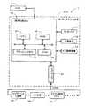
先ず、本実施形態に係る操作支援システム1の概略構成について図1を用いて説明する。図1は本実施形態に係る操作支援システム1の概略構成を示したブロック図である。   First, a schematic configuration of the operation support system 1 according to the present embodiment will be described with reference to FIG. FIG. 1 is a block diagram showing a schematic configuration of an operation support system 1 according to the present embodiment.

図1に示すように本実施形態に係る操作支援システム1は、車両内に設置され、ユーザによる操作を受け付ける左操作入力装置2及び右操作入力装置3と、ダッシュボード上に設置され車両のフロントガラスに映像を投影するヘッドアップディスプレイ(HUD)4と、左操作入力装置2及び右操作入力装置3とCAN等の車載ネットワークを介して接続された各種車載器(例えば、オーディオ、ナビゲーション装置)や車両機器(例えば、エアコン、パワーウィンドウ、ドアミラー)の制御装置等から構成されている。   As shown in FIG. 1, an operation support system 1 according to the present embodiment is installed in a vehicle, and a left operation input device 2 and a right operation input device 3 that receive an operation by a user, and a vehicle front that is installed on a dashboard. Head-up display (HUD) 4 that projects an image on glass, left operation input device 2 and right operation input device 3, and various vehicle-mounted devices (for example, audio and navigation devices) connected via a vehicle-mounted network such as CAN, It is comprised from the control apparatus etc. of vehicle equipment (for example, an air-conditioner, a power window, a door mirror).

ここで、左操作入力装置2は、図2に示すように車両のハンドル5の左側スポーク部分に配置されている。また、右操作入力装置3は、車両のハンドル5の右側スポーク部分に配置されている。左操作入力装置2及び右操作入力装置3の前面には、後述のようにユーザのタッチ操作を受け付けるタッチパッド(操作面)が設けられており、ユーザはハンドル5を支持した状態で、後述のタッチ操作により左操作入力装置2や右操作入力装置3を操作可能に構成されている。そして、本実施形態に係る操作支援システム1では、ユーザは左操作入力装置2や右操作入力装置3を介して、特にアプリケーションプログラムの実行や、実行されたアプリケーションプログラムによる車両に搭載された各種車載器や車両機器の操作等を行うことが可能に構成されている。例えば、インターネット、メール、ナビゲーション装置の目的地設定操作や地図画像のスクロール操作、エアコンの電源切り替え操作や温度調整操作、オーディオのチャンネル操作や音量調整操作、ウィンドウの開閉、ドアのロック等を行うことが可能である。また、特に本実施形態に係る操作支援システム1では、左操作入力装置2の操作面と右操作入力装置3の操作面とを同時に触れる(タッチする)ことによって、車両のエンジンのオン、オフ等の特殊な制御を行うことも可能である。   Here, the left operation input device 2 is disposed in the left spoke portion of the handle 5 of the vehicle as shown in FIG. The right operation input device 3 is disposed on the right spoke portion of the vehicle handle 5. On the front surface of the left operation input device 2 and the right operation input device 3, a touch pad (operation surface) for receiving a user's touch operation is provided as described later, and the user supports the handle 5 in a state described later. The left operation input device 2 and the right operation input device 3 can be operated by a touch operation. In the operation support system 1 according to the present embodiment, the user can execute various application programs and various types of vehicles mounted on the vehicle by the executed application programs, particularly via the left operation input device 2 and the right operation input device 3. It is configured to be able to operate a vessel and vehicle equipment. For example, Internet, mail, navigation device destination setting operation, map image scrolling operation, air conditioner power switching operation, temperature adjustment operation, audio channel operation, volume adjustment operation, window opening / closing, door locking, etc. Is possible. In particular, in the operation support system 1 according to the present embodiment, the vehicle engine is turned on and off by simultaneously touching (touching) the operation surface of the left operation input device 2 and the operation surface of the right operation input device 3. It is also possible to perform special control.

以下に、左操作入力装置2及び右操作入力装置3の構成についてより詳細に説明する。尚、左操作入力装置2と右操作入力装置3は基本的に同一の構成を有しており、以下では特に左操作入力装置2を例に挙げて説明することとし、右操作入力装置3の説明は省略する。図3は左操作入力装置2を示した斜視図であり、図4は図3の線X−Xで左操作入力装置2を切断した矢視断面図である。
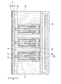
図3及び図4に示すように左操作入力装置2は、ユーザからのタッチ操作を検出するタッチパッド11と、タッチパッド11を振動させる為の圧電素子12と、タッチパッド11の下方において円柱形状のピンを上下動させる複数のピン駆動機構13と、ピン駆動機構13を所定の位置に固定する基部14と、後述の操作支援ECU15が搭載される制御基板16から基本的に構成される。尚、タッチ操作は、ユーザがタッチ面を触れることによって行う各種操作であり、例えばタッチパッド11のいずれかの地点に触れる(タッチする)操作、上記触れた状態(タッチ状態)を解除する操作、ドラッグ操作、フリック操作等がある。
Below, the structure of the left operation input device 2 and the right operation input device 3 is demonstrated in detail. Note that the left operation input device 2 and the right operation input device 3 basically have the same configuration, and in the following, the left operation input device 2 will be described as an example. Description is omitted. 3 is a perspective view showing the left operation input device 2, and FIG. 4 is a cross-sectional view taken along the line XX in FIG.
As shown in FIGS. 3 and 4, the left operation input device 2 includes a touch pad 11 that detects a touch operation from a user, a piezoelectric element 12 that vibrates the touch pad 11, and a cylindrical shape below the touch pad 11. This is basically composed of a plurality of pin drive mechanisms 13 that move the pins up and down, a base 14 that fixes the pin drive mechanism 13 at a predetermined position, and a control board 16 on which an operation support ECU 15 described later is mounted. The touch operation is various operations performed by the user touching the touch surface. For example, an operation of touching (touching) any point of the touch pad 11, an operation of releasing the touched state (touch state), There are drag operation and flick operation.

また、タッチパッド11は、上面側から順にタッチパッド11を保護するカバーシート17と、静電容量の変化によってユーザのタッチ操作を検出する導電膜18と、カバーシート17や導電膜18を前記基部14に対して上方に支持する天板19とから構成される。そして、操作支援ECU15は、後述のように所定の検出周期でユーザがタッチしたタッチ座標をタッチパッド11の座標系で検出する。尚、タッチ座標は、ユーザがタッチパッド11の操作面に触れた(静電容量方式では静電容量が変化したことを触れたとみなす)タッチ地点の位置の座標である。また、検出周期はタッチパッド11の種類によって異なるが、例えば200Hz〜2kHzとなる。尚、タッチパッド11としては静電容量方式以外の検出方式(例えば抵抗膜方式)を用いても良い。   The touch pad 11 includes a cover sheet 17 that protects the touch pad 11 in order from the upper surface side, a conductive film 18 that detects a user's touch operation based on a change in capacitance, the cover sheet 17 and the conductive film 18. 14 and a top plate 19 supported upward. And operation assistance ECU15 detects the touch coordinate which the user touched with the predetermined detection period by the coordinate system of the touchpad 11 so that it may mention later. Note that the touch coordinates are the coordinates of the position of the touch point where the user touches the operation surface of the touch pad 11 (it is assumed that the capacitance has changed in the capacitance method). Moreover, although a detection period changes with kinds of the touchpad 11, it becomes 200 Hz-2 kHz, for example. As the touch pad 11, a detection method (for example, a resistance film method) other than the electrostatic capacitance method may be used.

一方、天板19の下面には圧電素子12が取り付けられている。更に、タッチパッド11と基部14とは、四隅に配置された支持部20によって両者間に所定の間隙を設けるように構成されている。その結果、圧電素子12に信号電圧を加えることにより、圧電素子12を歪ませると、その歪によってタッチパッド11を上下方向に振動させることが可能となる。そして、本実施形態に係る操作支援システム1では、後述のようにタッチパッド11内の所定の領域がタッチオンされた場合や、ユーザがタッチパッド11の操作面を押下することによって操作面に所定量以上の変形(撓み)が生じた場合に、タッチパッド11を振動させる。それによって、ユーザが実在するボタンを操作した触感を与えることが可能となる。また、操作支援ECU15は、電圧値を変更することによって振動方向や振動の振幅を任意に設定することが可能である。振動周期は、圧電素子12の種類や設置態様によって異なるが、例えば250Hz〜2kHzとなる。尚、圧電素子12はタッチパッド11に直接接触して配置される必要はなく、タッチパッド11に振動を伝達できるのであれば、他の部材に対して配置されていても良い。また、タッチパッド11に振動を生じさせる手段としては、圧電素子12の代わりに小型の振動モータ等を用いても良い。   On the other hand, the piezoelectric element 12 is attached to the lower surface of the top plate 19. Further, the touch pad 11 and the base portion 14 are configured so as to provide a predetermined gap between them by support portions 20 arranged at the four corners. As a result, when the piezoelectric element 12 is distorted by applying a signal voltage to the piezoelectric element 12, the touch pad 11 can be vibrated in the vertical direction by the distortion. In the operation support system 1 according to the present embodiment, when a predetermined area in the touch pad 11 is touched on as described later, or when the user presses the operation surface of the touch pad 11, a predetermined amount is applied to the operation surface. When the above deformation (bending) occurs, the touch pad 11 is vibrated. As a result, it is possible to give a tactile sensation when the user operates an existing button. In addition, the operation support ECU 15 can arbitrarily set the vibration direction and the amplitude of vibration by changing the voltage value. The vibration period varies depending on the type and installation mode of the piezoelectric element 12, but is, for example, 250 Hz to 2 kHz. The piezoelectric element 12 does not need to be disposed in direct contact with the touch pad 11 and may be disposed with respect to other members as long as vibration can be transmitted to the touch pad 11. Further, as a means for causing the touch pad 11 to vibrate, a small vibration motor or the like may be used instead of the piezoelectric element 12.

また、圧電素子12は、タッチパッド11の操作面に生じた変形(撓み)を検出するセンサとしても機能する。即ち、天板19の下面に取り付けられた圧電素子12は、タッチパッド11の操作面が変形するとそれに伴って変形する。従って、操作支援ECU15は圧電素子12からの信号によってタッチパッド11の操作面に変形(撓み)が生じたことを検出することが可能となる。   The piezoelectric element 12 also functions as a sensor that detects deformation (deflection) generated on the operation surface of the touch pad 11. That is, when the operation surface of the touch pad 11 is deformed, the piezoelectric element 12 attached to the lower surface of the top plate 19 is deformed accordingly. Therefore, the operation support ECU 15 can detect that a deformation (deflection) has occurred on the operation surface of the touch pad 11 based on a signal from the piezoelectric element 12.

また、ピン駆動機構13は、基部14に対して3×3の計9箇所に所定の配置間隔(例えば縦横1cm間隔)で、ピン21の先端部がタッチパッド11に対向するように配置される。また、ピン21は図4の矢印Z方向に沿って上下動可能に支持されている。更に、ピン21の底面には挿入孔22が形成されており、挿入孔22には支持部材23が挿入されている。また、支持部材23の底面には圧電素子24が接続されている。そして、操作支援ECU15は、挿入孔22と支持部材23との間に生じる摩擦力を利用し、圧電素子24に信号電圧を加えて振動させることによってピン21を上方向及び下方向のいずれか一方の任意の方向に移動させることが可能となる。尚、ピン21の駆動機構の詳細については公知であるので省略する。   Further, the pin driving mechanism 13 is arranged at a predetermined arrangement interval (for example, 1 cm in length and width) at a total of nine locations of 3 × 3 with respect to the base portion 14 so that the tip portion of the pin 21 faces the touch pad 11. . The pin 21 is supported so as to be movable up and down along the arrow Z direction in FIG. Further, an insertion hole 22 is formed on the bottom surface of the pin 21, and a support member 23 is inserted into the insertion hole 22. A piezoelectric element 24 is connected to the bottom surface of the support member 23. Then, the operation support ECU 15 uses the frictional force generated between the insertion hole 22 and the support member 23 and applies a signal voltage to the piezoelectric element 24 to vibrate, thereby causing the pin 21 to move in either the upward direction or the downward direction. It is possible to move in any direction. The details of the drive mechanism of the pin 21 are well known and will be omitted.

また、タッチパッド11を構成する導電膜18及び天板19は、ピン21と対応する計9箇所の位置に貫通孔25が形成されており、ピン21が上方向に移動される場合には、タッチパッド11の上面よりも上側にピン21の先端が位置可能に構成されている。そして、操作支援ECU15は、各ピン駆動機構13を駆動させることによって、計9個のピン駆動機構13を図5に示すようなピン21の先端がタッチパッド11の操作面よりも下方にある“非突出状態”とピン21の先端がタッチパッド11の操作面よりも上方にある“突出状態”との間で選択的に切り換えることが可能となる。尚、カバーシート17は図5に示すようにタッチパッド11に対して突出された状態にあるピン21を保護する為に、伸縮性のある材料(例えばシリコン樹脂)等を用いて形成することが望ましい。   In addition, the conductive film 18 and the top plate 19 constituting the touch pad 11 have through holes 25 formed at a total of nine positions corresponding to the pins 21, and when the pins 21 are moved upward, The tip of the pin 21 can be positioned above the upper surface of the touch pad 11. Then, the operation support ECU 15 drives each pin driving mechanism 13 so that the tip of the pin 21 as shown in FIG. 5 is located below the operation surface of the touch pad 11 in the nine pin driving mechanisms 13. It is possible to selectively switch between the “non-projecting state” and the “projecting state” where the tip of the pin 21 is above the operation surface of the touch pad 11. As shown in FIG. 5, the cover sheet 17 may be formed using a stretchable material (for example, silicon resin) or the like in order to protect the pins 21 that are projected from the touch pad 11. desirable.

また、左操作入力装置2及び右操作入力装置3の内、特に左操作入力装置2の操作面上には、図3に示すようにハードウェアの操作部である操作ボタン27が設けられている。ここで、操作ボタン27としては例えばホームボタンやショートカットボタンがある。そして、後述のようにアプリケーションの操作を行っている状態でホームボタンが押下されると、該アプリケーションを一旦終了し、HUD4によって表示される表示画面も初期画面へと復帰される。また、ショートカットボタンが押下されると、予めショートカットボタンに対応付けられた機能(例えば、ウェブブラウザの起動、地図の縮尺変更操作、エアコンの設定温度変更操作等)が実行される。尚、操作ボタン27は右操作入力装置3の操作面上にも設ける構成としても良い。また、操作ボタン27をハードウェアの操作部であるハードキーではなく仮想的に操作面上に配置されるキーとしても良い。その場合には、操作支援ECU15は、タッチ座標が予め操作ボタン27に対応付けられた座標範囲にある場合に、操作ボタン27が押下されたと判定する。   In addition, on the operation surface of the left operation input device 2 and the right operation input device 3, particularly on the operation surface of the left operation input device 2, an operation button 27 that is a hardware operation unit is provided as shown in FIG. 3. . Here, examples of the operation button 27 include a home button and a shortcut button. When the home button is pressed while the application is being operated as will be described later, the application is temporarily terminated, and the display screen displayed by the HUD 4 is also restored to the initial screen. When the shortcut button is pressed, functions associated with the shortcut button in advance (for example, activation of a web browser, map scale change operation, air conditioner set temperature change operation, etc.) are executed. The operation button 27 may be provided on the operation surface of the right operation input device 3. In addition, the operation button 27 may be a key that is virtually arranged on the operation surface instead of a hardware key that is a hardware operation unit. In this case, the operation support ECU 15 determines that the operation button 27 has been pressed when the touch coordinates are in the coordinate range associated with the operation button 27 in advance.

また、制御基板16に搭載される操作支援ECU(エレクトロニック・コントロール・ユニット)15は、左操作入力装置2の全体の制御を行う電子制御ユニットであり、演算装置及び制御装置としてのCPU31、並びにCPU31が各種の演算処理を行うにあたってワーキングメモリとして使用されるRAM32、制御用のプログラムのほか、後述の操作支援処理プログラム(図8参照)等が記録されたROM33、ROM33から読み出したプログラムや後述のメニューアイコンの選択履歴やタッチ座標の履歴を記憶するフラッシュメモリ34等の内部記憶装置を備えている。尚、操作支援ECU15は、処理アルゴリズムとしての各種手段を構成する。例えば、操作対象物表示手段は、複数の操作対象物(アイコン等)を車両のフロントガラス36に表示する。車両制御手段は、左操作入力装置2のタッチパッド11の操作面と右操作入力装置3のタッチパッド11の操作面とに同時に触れる操作を受け付けた場合に、HUD4を含む車両機器のいずれかを制御する。タッチ時間検出手段は、左操作入力装置2の操作面と右操作入力装置3の操作面とに同時に触れる操作を受け付けた場合に、その後に両方の操作面において同時に触れる状態を継続した時間を検出する。   An operation support ECU (Electronic Control Unit) 15 mounted on the control board 16 is an electronic control unit that controls the entire left operation input device 2, and includes a CPU 31 as a calculation device and a control device, and a CPU 31. In addition to the RAM 32 used as a working memory and a control program in performing various arithmetic processes, a ROM 33 in which an operation support processing program (see FIG. 8) described later is recorded, a program read from the ROM 33, and a menu described later An internal storage device such as a flash memory 34 for storing icon selection history and touch coordinate history is provided. The operation support ECU 15 constitutes various means as processing algorithms. For example, the operation object display means displays a plurality of operation objects (icons or the like) on the windshield 36 of the vehicle. When the vehicle control means receives an operation of simultaneously touching the operation surface of the touchpad 11 of the left operation input device 2 and the operation surface of the touchpad 11 of the right operation input device 3, any one of the vehicle devices including the HUD 4 is selected. Control. The touch time detection means detects a time during which the touch surface is continuously touched on both operation surfaces after receiving an operation to touch the operation surface of the left operation input device 2 and the operation surface of the right operation input device 3 at the same time. To do.

また、HUD4は、図2に示すようにダッシュボード35上に設置されており、映像の投射方向が運転席の前方のフロントガラス36の下縁付近となるように設定されている。そして、フロントガラス36の表示対象領域37に対して各種画像を表示する。   The HUD 4 is installed on the dashboard 35 as shown in FIG. 2, and is set so that the image projection direction is near the lower edge of the windshield 36 in front of the driver's seat. Various images are displayed on the display target area 37 of the windshield 36.

ここで、図6及び図7はHUD4によってフロントガラス36の表示対象領域37に表示される画像の一例を示した図である。
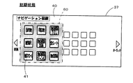
先ず、ACCがオンされた直後の状態では表示対象領域37において図6に示すメイン画面40が表示される。メイン画面40は、操作支援システム1において実行可能な各種アプリケーションを実行する為の操作を受け付ける基本操作画面であり、ホーム画面やデスクトップ等が相当する。図6に示すように、メイン画面40には、複数のメニューアイコン(操作対象物)41が配置されている。メニューアイコン41は、操作支援システム1において実行可能なアプリケーションを起動させる為に選択且つ操作されるアイコンであり、ユーザによってメニューアイコン41が操作されると、操作されたメニューアイコン41に対応したアプリケーションの起動が開始される。また、起動されるアプリケーションには、ウェブブラウザやメールアプリ以外に、各種車載器(例えば、オーディオ、ナビゲーション装置)や車両機器(例えば、エアコン、パワーウィンドウ、ドアミラー)に対する操作を行う為のアプリケーションも含まれる。そして、メイン画面40においていずれかのメニューアイコン41が選択且つ操作されると、対応するアプリケーションが起動され、起動されたアプリケーションに対応する操作画面が表示される。特に、車両に搭載された各種車載器や車両機器の操作に対応したアプリケーションが起動された場合には、図7に示すように設定操作画面42(図7に示す例ではエアコンの操作に対応)が表示される。設定操作画面42では、操作対象となる機器の現在の設定状態(パラメータ等)が設定アイコン43〜45内にそれぞれ表示され、更にその設定状態の確認や変更操作が可能となる。
Here, FIGS. 6 and 7 are diagrams showing an example of an image displayed on the display target area 37 of the windshield 36 by the HUD 4.
First, in a state immediately after the ACC is turned on, the main screen 40 shown in FIG. The main screen 40 is a basic operation screen that receives operations for executing various applications that can be executed in the operation support system 1, and corresponds to a home screen, a desktop, or the like. As shown in FIG. 6, a plurality of menu icons (operation objects) 41 are arranged on the main screen 40. The menu icon 41 is an icon that is selected and operated to start an application that can be executed in the operation support system 1. When the menu icon 41 is operated by the user, an application corresponding to the operated menu icon 41 is displayed. Start is started. In addition to the web browser and mail application, the applications to be started include applications for performing operations on various vehicle-mounted devices (for example, audio and navigation devices) and vehicle devices (for example, air conditioners, power windows, door mirrors). It is. When any menu icon 41 is selected and operated on the main screen 40, the corresponding application is activated, and an operation screen corresponding to the activated application is displayed. In particular, when an application corresponding to the operation of various vehicle-mounted devices and vehicle equipment mounted on the vehicle is activated, a setting operation screen 42 (corresponding to the operation of the air conditioner in the example shown in FIG. 7) is shown in FIG. Is displayed. On the setting operation screen 42, the current setting state (parameters, etc.) of the device to be operated is displayed in the setting icons 43 to 45, and the setting state can be confirmed and changed.

また、メイン画面40において表示されるメニューアイコン41の内、所定数のメニューアイコン41は、他のアイコンよりも拡大して表示され、また、アイコンを囲む枠も太くなる。ここで、本実施形態に係る操作支援システム1では、操作面の面積が狭いタッチパッド11を用いてメニューアイコン41の選択を行うので、右操作入力装置3によって直接的に選択対象(以下、選択対象候補)とすることが可能なメニューアイコン41の数に限界がある。例えば、本実施形態では右操作入力装置3が備えるピン21の数である9つのアイコンまで、選択対象候補とすることが可能である。従って、メイン画面40に表示されるメニューアイコン41が多数ある場合には、選択対象候補とするメニューアイコン41を識別して表示する必要があり、選択対象候補とするメニューアイコン41は他のアイコンよりも拡大して表示され、また、アイコンを囲む枠も太くなる。更に、選択対象候補とするメニューアイコン41は、右操作入力装置3のタッチパッド11に配置されるピン21の配置態様と対応する配置態様で表示する。即ち、3×3の等間隔の配置間隔で配置される。尚、選択対象候補とするメニューアイコン41は、後述するように左操作入力装置2のタッチパッド11の操作面に対するドラッグ操作又はフリック操作によって切り換えることが可能となる。   In addition, a predetermined number of menu icons 41 among the menu icons 41 displayed on the main screen 40 are displayed in an enlarged manner than the other icons, and the frame surrounding the icons is also thicker. Here, in the operation support system 1 according to the present embodiment, since the menu icon 41 is selected using the touch pad 11 having a small operation surface area, the selection target (hereinafter referred to as the selection) is directly selected by the right operation input device 3. There is a limit to the number of menu icons 41 that can be set as target candidates). For example, in this embodiment, up to nine icons, which is the number of pins 21 included in the right operation input device 3, can be selected as candidates for selection. Therefore, when there are a large number of menu icons 41 displayed on the main screen 40, it is necessary to identify and display the menu icon 41 as a selection target candidate. Is enlarged and the frame surrounding the icon becomes thicker. Furthermore, the menu icon 41 as a selection target candidate is displayed in an arrangement manner corresponding to the arrangement manner of the pins 21 arranged on the touch pad 11 of the right operation input device 3. That is, they are arranged at an equal interval of 3 × 3. Note that the menu icon 41 that is a selection target candidate can be switched by a drag operation or a flick operation on the operation surface of the touch pad 11 of the left operation input device 2 as described later.

また、メニューアイコン41が特に多数存在する場合には、起動されるアプリケーションの種類によって複数のグループに区分する。そして、グループ単位で該グループに属するメニューアイコン41をメイン画面40に表示するように構成する。例えば、図6に示す例ではナビゲーション装置に関する操作を行う為のアプリケーションを起動させるメニューアイコン41のグループと、オーディオに関する操作を行う為のアプリケーションを起動させるメニューアイコン41のグループと、一般的なアプリケーションやその他の車両機器に関する操作を行う為のアプリケーションを起動させるメニューアイコン41のグループとに区分され、現時点でその他の車両機器に関するメニューアイコン41のグループが表示対象となっている。また、ユーザは左操作入力装置2において左右へのフリック操作やドラッグ操作を行うことによって、メイン画面40に表示対象となるグループを順次変更することが可能である。   When there are a particularly large number of menu icons 41, the menu icons 41 are divided into a plurality of groups depending on the type of application to be activated. The menu icons 41 belonging to the group are displayed on the main screen 40 in units of groups. For example, in the example illustrated in FIG. 6, a group of menu icons 41 for starting an application for performing operations related to the navigation device, a group of menu icons 41 for starting an application for performing operations regarding audio, a general application, It is divided into a group of menu icons 41 for starting applications for performing operations related to other vehicle devices, and the group of menu icons 41 related to other vehicle devices is a display target at the present time. Further, the user can sequentially change the group to be displayed on the main screen 40 by performing a flicking operation or a dragging operation to the left and right with the left operation input device 2.

また、ユーザは右操作入力装置3を操作することによって選択対象候補となっているメニューアイコン41の内から任意のメニューアイコン41を選択及び操作することが可能となる。具体的には、選択を希望するメニューアイコン41の位置に対応するタッチパッド11の位置(例えば、図6に示す例で『エアコン』のメニューアイコン41を選択する場合には左上のピン21周辺)を右操作入力装置3においてタッチオンすることによってメニューアイコン41が選択される。尚、メニューアイコン41の位置に対応するピン21を押下することや操作面に一定量以上の撓みを生じさせることを選択の条件としても良い。そして、いずれかのメニューアイコン41が選択且つ操作されると、対応するアプリケーションが起動され、起動されたアプリケーションに対応する操作画面が表示される。
尚、メイン画面40や設定操作画面42を表示する表示手段としては、HUD4の代わりに、車両内に設置された液晶ディスプレイや有機ELディスプレイ、車両の運転者の頭部に装着可能に構成されるヘッドマウントディスプレイ(HMD)等を用いても良い。また、ナビゲーション装置のディスプレイを用いても良い。
Further, the user can select and operate an arbitrary menu icon 41 from among the menu icons 41 that are candidates for selection by operating the right operation input device 3. Specifically, the position of the touch pad 11 corresponding to the position of the menu icon 41 desired to be selected (for example, when the menu icon 41 of “air conditioner” is selected in the example shown in FIG. 6, the area around the pin 21 at the upper left) Is touched on in the right operation input device 3, and the menu icon 41 is selected. It should be noted that pressing the pin 21 corresponding to the position of the menu icon 41 or causing the operation surface to bend a certain amount or more may be used as the selection condition. When one of the menu icons 41 is selected and operated, a corresponding application is activated, and an operation screen corresponding to the activated application is displayed.
The display means for displaying the main screen 40 and the setting operation screen 42 is configured to be mounted on the head of the driver of the vehicle, such as a liquid crystal display or an organic EL display installed in the vehicle, instead of the HUD 4. A head mounted display (HMD) or the like may be used. Further, a display of a navigation device may be used.

一方、左操作入力装置2や右操作入力装置3が有するCAN(コントローラエリアネットワーク)インターフェース47は、車両内に設置された各種車載器や車両機器の制御装置間で多重通信を行う車載ネットワーク規格であるCANに対して、データの入出力を行うインターフェースである。そして、操作支援ECU15は、CANを介して、各種車載器や車両機器の制御装置(例えば、ナビゲーション装置48、AV装置49、エアコン制御ECU50等)と相互通信可能に接続される。そして、操作支援ECU15は、特定のアプリケーションが起動された状態で左操作入力装置2や右操作入力装置3においてユーザの操作を受け付けた場合に、操作信号を各種車載器や車両機器の制御装置へと送信することによって、左操作入力装置2や右操作入力装置3を介した各種車載器や車両機器の操作を行う。   On the other hand, the CAN (controller area network) interface 47 included in the left operation input device 2 and the right operation input device 3 is an in-vehicle network standard that performs multiplex communication between various in-vehicle devices installed in a vehicle and control devices for vehicle equipment. This is an interface for inputting / outputting data to / from a certain CAN. The operation support ECU 15 is connected to a control device (for example, the navigation device 48, the AV device 49, the air conditioner control ECU 50, etc.) of various vehicle-mounted devices and vehicle equipment via the CAN so as to be able to communicate with each other. When the operation support ECU 15 receives a user operation in the left operation input device 2 or the right operation input device 3 in a state in which a specific application is activated, the operation support ECU 15 transmits an operation signal to various vehicle-mounted devices or vehicle device control devices. Is transmitted, the various on-vehicle devices and vehicle equipment are operated via the left operation input device 2 and the right operation input device 3.

続いて、前記構成を有する操作支援システム1において操作支援ECU15が実行する操作支援処理プログラムについて図8に基づき説明する。図8は本実施形態に係る操作支援処理プログラムのフローチャートである。ここで、操作支援処理プログラムは車両のACCがONされた後に実行され、左操作入力装置2及び右操作入力装置3を介して各種アプリケーションの起動及び操作を行うプログラムである。尚、以下の図8、図9、図13、図17、図19及び図20にフローチャートで示されるプログラムは、操作支援システム1が備えているRAM32やROM33に記憶されており、CPU31により実行される。   Next, an operation support processing program executed by the operation support ECU 15 in the operation support system 1 having the above configuration will be described with reference to FIG. FIG. 8 is a flowchart of the operation support processing program according to the present embodiment. Here, the operation support processing program is a program that is executed after the ACC of the vehicle is turned on, and activates and operates various applications via the left operation input device 2 and the right operation input device 3. The programs shown in the flowcharts of FIGS. 8, 9, 13, 17, 19, and 20 below are stored in the RAM 32 and ROM 33 provided in the operation support system 1, and are executed by the CPU 31. The

先ず、操作支援処理プログラムではステップ(以下、Sと略記する)1において、CPU31は、操作支援処理プログラムに関する各種の初期化処理を実行する。初期化処理では、タッチ座標の履歴や後述の選択対象候補アイコンの設定情報等が初期化される。   First, in step (hereinafter abbreviated as S) 1 in the operation support processing program, the CPU 31 executes various initialization processes related to the operation support processing program. In the initialization process, a history of touch coordinates, setting information of selection target candidate icons described later, and the like are initialized.

次に、S2においてCPU31は、タッチパッド11から送信される検出信号に基づいて、左操作入力装置2及び右操作入力装置3のいずれかのタッチパッド11の操作面において、ユーザが少なくとも1点以上をタッチしている状態(以下、タッチ状態という)にあるか否かを判定する。例えば、タッチパッド11が抵抗膜方式や静電容量方式である場合には、所定値以上の圧力を検出した場合や所定値以上の静電容量の変化を検出した場合に、ユーザがタッチパッド11をタッチした状態にあると判定する。   Next, in S <b> 2, based on the detection signal transmitted from the touch pad 11, the CPU 31 receives at least one point on the operation surface of the touch pad 11 of the left operation input device 2 or the right operation input device 3. It is determined whether or not it is in a touched state (hereinafter referred to as a touch state). For example, when the touch pad 11 is of a resistive film type or a capacitance type, the user can detect the touch pad 11 when a pressure greater than a predetermined value is detected or when a change in capacitance greater than the predetermined value is detected. It is determined that is touched.

そして、左操作入力装置2及び右操作入力装置3のいずれかのタッチパッド11の操作面をタッチしたタッチ状態にあると判定された場合(S2:YES)には、S3へと移行する。それに対して、左操作入力装置2及び右操作入力装置3のいずれのタッチパッド11の操作面もタッチした状態にないと判定された場合(S2:NO)には、タッチ状態となるまで待機する。   And when it determines with it being in the touch state which touched the operation surface of any touchpad 11 of the left operation input device 2 and the right operation input device 3 (S2: YES), it transfers to S3. On the other hand, when it is determined that neither the operation surface of the touch pad 11 of the left operation input device 2 or the right operation input device 3 is in a touched state (S2: NO), the process waits until the touch state is reached. .

S3においてCPU31は、特に左操作入力装置2のタッチパッド11の操作面と右操作入力装置3のタッチパッド11の操作面とにユーザが同時にタッチする(触れる)操作が行われたか否か判定する。尚、「同時に触れる」とは厳密に同一時刻に触れることに加えて、触れた時刻の差分が所定の許容範囲時間内である場合も含む。ここで、許容範囲時間は、後述する駆動源(例えば、エンジン)をオフ状態からオン状態にする場合に設定される許容範囲時間に比べて駆動源をオン状態からオフ状態にする場合に設定する許容範囲時間を短くする方が望ましい。その理由としては、駆動源をオフ状態からオン状態にする場合には車速が検出されている場合がほとんど存在しないと考えられるので、誤操作により駆動源をオフ状態からオン状態になったとしても車両等に問題が生じる可能性が低い。一方、駆動源をオフ状態にする場合には車速が検出されている場合も存在するため、誤操作により駆動源をオン状態からオフ状態にした場合に車両等に問題が生じる可能性があるためである。   In S3, the CPU 31 determines whether or not an operation has been performed in which the user simultaneously touches (touches) the operation surface of the touch pad 11 of the left operation input device 2 and the operation surface of the touch pad 11 of the right operation input device 3 in particular. . Note that “touching at the same time” includes not only strictly touching the same time, but also the case where the difference between the touched times is within a predetermined allowable time range. Here, the allowable range time is set when the drive source is changed from the on state to the off state as compared to an allowable range time set when a drive source (for example, an engine) described later is changed from the off state to the on state. It is desirable to reduce the allowable range time. The reason for this is that when the drive source is switched from the off state to the on state, it is considered that there is almost no case where the vehicle speed is detected, so even if the drive source is switched from the off state to the on state due to an erroneous operation, the vehicle It is unlikely that problems will occur. On the other hand, there is a case where the vehicle speed is detected when the drive source is turned off, and there is a possibility that a problem may occur in the vehicle or the like when the drive source is turned off from the on state due to an erroneous operation. is there.

そして、左操作入力装置2のタッチパッド11の操作面と右操作入力装置3のタッチパッド11の操作面とにユーザが同時にタッチする操作が行われたと判定された場合(S3:YES)には、S4へと移行する。それに対して、左操作入力装置2のタッチパッド11の操作面と右操作入力装置3のタッチパッド11の操作面とにユーザが同時にタッチする操作が行われていないと判定された場合(S3:NO)には、S5へと移行する。   When it is determined that an operation in which the user simultaneously touches the operation surface of the touch pad 11 of the left operation input device 2 and the operation surface of the touch pad 11 of the right operation input device 3 is performed (S3: YES). To S4. On the other hand, when it is determined that the user does not perform an operation of simultaneously touching the operation surface of the touch pad 11 of the left operation input device 2 and the operation surface of the touch pad 11 of the right operation input device 3 (S3: NO), the process proceeds to S5.

S4においてCPU31は、後述の両タッチ処理(図9)が実行される。尚、両タッチ処理は、後述のように左操作入力装置2のタッチパッド11の操作面と右操作入力装置3のタッチパッド11の操作面で同時に受け付けたタッチ操作に基づいて、エンジンのオン制御、オフ制御やHUD4の電源制御等の特殊な車両制御を行う処理である。その後、S23へと移行する。   In S4, the CPU 31 executes a double-touch process (FIG. 9) described later. It should be noted that both touch processes are performed as described below, based on the touch operation received simultaneously on the operation surface of the touch pad 11 of the left operation input device 2 and the operation surface of the touch pad 11 of the right operation input device 3. This is a process for performing special vehicle control such as off control and HUD4 power control. Thereafter, the process proceeds to S23.

ここで、前記S4において実行される同時タッチ処理のサブ処理について図9に基づき説明する。図9は同時タッチ処理のサブ処理プログラムのフローチャートである。   Here, the sub-process of the simultaneous touch process executed in S4 will be described with reference to FIG. FIG. 9 is a flowchart of a sub-processing program for simultaneous touch processing.

先ず、S31においてCPU31は、CANによって接続された車両制御ECUと通信を行うことによって、車両機器の制御状態として車両のエンジンがオフの状態にあるか否かを判定する。   First, in S31, the CPU 31 determines whether or not the engine of the vehicle is in an off state as a control state of the vehicle equipment by communicating with the vehicle control ECU connected by the CAN.

そして、車両のエンジンがオフの状態にあると判定された場合(S31:YES)には、S32へと移行する。それに対して、車両のエンジンがオンの状態にあると判定された場合(S31:NO)には、S33へと移行する。   And when it determines with the engine of a vehicle being in the state of OFF (S31: YES), it transfers to S32. On the other hand, when it is determined that the engine of the vehicle is on (S31: NO), the process proceeds to S33.

S32においてCPU31は、前記S31において車両機器の制御状態としてエンジンがオフ状態であるために、タッチパッド11の操作面で同時に受け付けたタッチ操作に対応する車両機器の制御内容がエンジン始動であると判定して、エンジンの始動信号をCANを介して車両制御ECUへと送信する。一方、エンジンの始動信号を受信した車両制御ECUは、停止状態にある車両のエンジンを始動する。その結果、左操作入力装置2及び右操作入力装置3を介したエンジンの駆動制御を行うことが可能となる。その後、S23へと移行する。   In S32, the CPU 31 determines that the control content of the vehicle device corresponding to the touch operation simultaneously received on the operation surface of the touch pad 11 is the engine start because the engine is in the off state as the control state of the vehicle device in S31. Then, an engine start signal is transmitted to the vehicle control ECU via the CAN. On the other hand, the vehicle control ECU which has received the engine start signal starts the engine of the vehicle in a stopped state. As a result, it becomes possible to perform engine drive control via the left operation input device 2 and the right operation input device 3. Thereafter, the process proceeds to S23.

S33においてCPU31は、左操作入力装置2と右操作入力装置3の両方のタッチパッド11の操作面に同時にタッチした後において、左操作入力装置2と右操作入力装置3の両方のタッチパッド11の操作面において同時に触れる状態を継続した継続時間Tを検出する。ここで、継続時間Tが左操作入力装置2と右操作入力装置3の両方のタッチパッド11の操作面において同時に触れる状態を継続した時点から計時される理由について説明する。近年、駆動源をオン状態にするためにスターターボタンが配設されている車両が増えているが、これらは運転者が比較的操作しにくい位置にスターターボタンを配設して誤操作を防ぐようにしている。これに対して、本発明では左操作入力装置2と右操作入力装置3はハンドルに配設しているので、タッチパッドの一方が押されている状態でタッチパッドの他方が誤って押された場合にこれら2つの操作入力装置への同時入力(タッチ操作)がユーザに為されたと誤判定しないようにする必要があるためである。さらに、継続時間Tをエンジンのオン状態からオフ状態へ変更する際に用いていて、エンジンのオフ状態からオン状態へ変更する際に用いていない理由は、駆動源の制御と並行して後述する画面の表示状態(オン状態)と非表示状態(オフ状態)を制御するため以外にも車両が走行中(車速が検出されている場合)に誤って駆動源をオン状態からオフ状態とされないようにして車両等に問題が生じるのを防止するためである。   In S <b> 33, the CPU 31 simultaneously touches the operation surfaces of the touchpads 11 of both the left operation input device 2 and the right operation input device 3, and then touches both the touchpads 11 of the left operation input device 2 and the right operation input device 3. The duration T during which the touching state on the operation surface is continued is detected. Here, the reason why the continuation time T is measured from the point of time when the touch surfaces of the touchpads 11 of both the left operation input device 2 and the right operation input device 3 are simultaneously touched will be described. In recent years, an increasing number of vehicles are provided with starter buttons to turn on the drive source, but these starter buttons are arranged at positions where it is relatively difficult for the driver to operate to prevent erroneous operation. ing. On the other hand, in the present invention, since the left operation input device 2 and the right operation input device 3 are disposed on the handle, the other touch pad is accidentally pressed while one of the touch pads is pressed. This is because it is necessary to prevent erroneous determination that simultaneous input (touch operation) to these two operation input devices has been performed by the user. Further, the reason why the duration T is used when changing the engine from the on state to the off state and not used when changing the engine from the off state to the on state will be described later in parallel with the control of the drive source. In addition to controlling the display state (on state) and non-display state (off state) of the screen, the drive source is not accidentally switched from the on state to the off state while the vehicle is running (when the vehicle speed is detected). This is to prevent problems in the vehicle and the like.

S34においてCPU31は、前記S33で検出された継続時間Tが所定時間以上であるか否かを判定する。ここで、所定時間は例えば3secとし、RAM32等の記憶手段に記憶される。   In S34, the CPU 31 determines whether or not the duration T detected in S33 is equal to or longer than a predetermined time. Here, the predetermined time is 3 sec, for example, and is stored in the storage means such as the RAM 32.

そして、前記S33で検出された継続時間Tが所定時間以上であると判定された場合(S34:YES)には、S35へと移行する。それに対して、前記S33で検出された継続時間Tが所定時間未満であると判定された場合(S34:NO)には、S37へと移行する。   And when it determines with the continuation time T detected by said S33 being more than predetermined time (S34: YES), it transfers to S35. On the other hand, when it is determined that the duration T detected in S33 is less than the predetermined time (S34: NO), the process proceeds to S37.

S35においてCPU31は、CANを介して車両制御ECUと通信することにより、車両のパーキングブレーキが作動した状態であるか否かを判定する。   In S35, the CPU 31 determines whether or not the parking brake of the vehicle is in operation by communicating with the vehicle control ECU via the CAN.

そして、車両機器の制御状態として車両のパーキングブレーキが作動した状態であると判定された場合(S35:YES)には、S36へと移行する。それに対して、車両のパーキングブレーキが作動した状態でないと判定された場合(S35:NO)には、S37へと移行する。   And when it determines with it being the state which the parking brake of the vehicle act | operated as a control state of vehicle equipment (S35: YES), it transfers to S36. On the other hand, when it is determined that the parking brake of the vehicle is not activated (S35: NO), the process proceeds to S37.

S36においてCPU31は、S31とS35の判定からタッチパッド11の操作面で同時に受け付けたタッチ操作に対応する車両の制御内容がエンジンの停止に相当すると判定して、エンジンの停止信号をCANを介して車両制御ECUへと送信する。一方、エンジンの停止信号を受信した車両制御ECUは、駆動状態にある車両のエンジンを停止する。その結果、左操作入力装置2及び右操作入力装置3を介したエンジンの駆動制御を行うことが可能となる。その後、S23へと移行する。   In S36, the CPU 31 determines from the determinations in S31 and S35 that the control content of the vehicle corresponding to the touch operation received simultaneously on the operation surface of the touch pad 11 corresponds to the engine stop, and sends an engine stop signal via the CAN. It transmits to vehicle control ECU. On the other hand, the vehicle control ECU that has received the engine stop signal stops the engine of the vehicle in the drive state. As a result, it becomes possible to perform engine drive control via the left operation input device 2 and the right operation input device 3. Thereafter, the process proceeds to S23.

一方、S37においてCPU31は、車両機器の制御状態としてHUD4の電源がオンされているか否か(即ち、フロントガラス36の表示対象領域37に対してメイン画面40や設定操作画面42等の何らかの表示画面が表示されているか否か)を判定する。   On the other hand, in S37, the CPU 31 determines whether or not the power of the HUD 4 is turned on as a control state of the vehicle equipment (that is, any display screen such as the main screen 40 and the setting operation screen 42 with respect to the display target area 37 of the windshield 36). Whether or not is displayed).

そして、車両機器の制御状態としてHUD4の電源がオンされていると判定された場合(S37:YES)には、S38へと移行する。それに対して、HUD4の電源がオフされていると判定された場合(S37:NO)には、S39へと移行する。   And when it determines with the power supply of HUD4 being turned ON as a control state of a vehicle apparatus (S37: YES), it transfers to S38. On the other hand, when it is determined that the power of the HUD 4 is turned off (S37: NO), the process proceeds to S39.

S38においてCPU31は、電源オフ信号をHUD4へと送信する。一方、電源オフ信号を受信したHUD4のECUは、HUD4の電源をオフする。その結果、左操作入力装置2及び右操作入力装置3を介したHUD4の制御を行うことが可能となる。その後、S23へと移行する。尚、HUD4の電源はオンした状態のままで表示機能のみオフする制御を行っても良い。   In S38, the CPU 31 transmits a power-off signal to the HUD 4. On the other hand, the ECU of HUD 4 that has received the power-off signal turns off the power of HUD 4. As a result, it is possible to control the HUD 4 via the left operation input device 2 and the right operation input device 3. Thereafter, the process proceeds to S23. Note that control may be performed to turn off only the display function while the power of the HUD 4 is kept on.

一方、S39においてCPU31は、電源オン信号をHUD4へと送信する。一方、電源オン信号を受信したHUD4のECUは、HUD4の電源をオンする。その結果、左操作入力装置2及び右操作入力装置3を介したHUD4の制御を行うことが可能となる。   On the other hand, in S39, the CPU 31 transmits a power-on signal to the HUD 4. On the other hand, the ECU of the HUD 4 that has received the power-on signal turns on the power of the HUD 4. As a result, it is possible to control the HUD 4 via the left operation input device 2 and the right operation input device 3.

そして、電源がオンされたHUD4は、フロントガラス36の表示対象領域37に対してメイン画面40を表示する。メイン画面40には、前記したように左操作入力装置2及び右操作入力装置3による操作によって操作及び選択の対象となる複数のメニューアイコン41が表示される(図6参照)。また、前記したようにメイン画面40では、右操作入力装置3によって直接的に選択対象とすることが可能、即ち右操作入力装置3によって選択対象候補となるメニューアイコン41(以下、選択対象候補アイコンという)が設定されている。例えば、図6に示す例では『エアコン』〜『通信』までの9個のアイコンが選択対象候補アイコンであり、選択対象候補アイコンは他のアイコンと識別可能(例えば、サイズが拡大され、アイコンを囲む枠を太く)に強調表示される。   Then, the HUD 4 whose power is turned on displays the main screen 40 on the display target area 37 of the windshield 36. On the main screen 40, as described above, a plurality of menu icons 41 to be operated and selected by operations by the left operation input device 2 and the right operation input device 3 are displayed (see FIG. 6). Further, as described above, the main screen 40 can be directly selected by the right operation input device 3, that is, the menu icon 41 (hereinafter, the selection target candidate icon) that becomes the selection target candidate by the right operation input device 3. Is set). For example, in the example illustrated in FIG. 6, nine icons from “air conditioner” to “communication” are selection target candidate icons, and the selection target candidate icons can be distinguished from other icons (for example, the size is increased and the icon is displayed). The surrounding frame is highlighted).

また、表示された時点(初期状態)でのメイン画面40においては、フラッシュメモリ34に記憶されたメニューアイコン41の選択履歴を読み出し、選択回数の多いメニューアイコン41を優先して選択対象候補アイコンに設定する。具体的には、初期状態ではメイン画面40において選択回数の高いメニューアイコン41から順に、左上から右下方向へと並べて表示され、メイン画面40に表示された複数のメニューアイコン41の内、最も左上側に位置する3×3の計9個のメニューアイコン41が選択対象候補アイコンとなる。例えば、図10は、ACCがオンされた直後に表示されるメイン画面40の一例を示すものであり、選択対象候補アイコンとして選択回数の高い順に『目的地』、『地図縮尺』、『地図スクロール』・・・、『地点登録』の9つのナビゲーション装置に係るメニューアイコン41が設定される。また、図10に示すように起動されるアプリケーションの種類によってメニューアイコン41が複数のグループに区分されている場合には、グループ毎に選択回数順に並べて表示する。更に、初期状態では予め決められた特定のグループ(例えばナビゲーション装置に関する操作を行う為のアプリケーションを起動させるメニューアイコン41)をメイン画面40に表示しても良いし、選択回数の多いグループを優先的に表示することとしても良い。   Further, on the main screen 40 at the time of display (initial state), the selection history of the menu icon 41 stored in the flash memory 34 is read, and the menu icon 41 having a large number of selections is given priority as a selection target candidate icon. Set. Specifically, in the initial state, the menu icons 41 with the highest selection count are displayed in order from the upper left to the lower right in the main screen 40, and among the plurality of menu icons 41 displayed on the main screen 40, the upper left A total of nine menu icons 41 of 3 × 3 located on the side are selection target candidate icons. For example, FIG. 10 shows an example of the main screen 40 that is displayed immediately after the ACC is turned on. As the selection target candidate icons, “Destination”, “Map Scale”, and “Map Scroll” are displayed in descending order of selection frequency. ..., Menu icons 41 relating to nine navigation devices “point registration” are set. Also, as shown in FIG. 10, when the menu icons 41 are divided into a plurality of groups depending on the type of application to be activated, the menu icons 41 are arranged and displayed in order of the number of selections for each group. Further, in the initial state, a predetermined group (for example, a menu icon 41 for starting an application for performing an operation related to the navigation device) may be displayed on the main screen 40, or a group with a large number of selections is given priority. It is good also as displaying on.

また、メイン画面40に表示された選択対象候補アイコンは、後述の左操作入力装置2のタッチパッド11の操作面に対するドラッグ操作やフリック操作によって他のメニューアイコン41へと切り換えることが可能であるが、選択対象候補アイコンとするメニューアイコン41の配置態様は固定する。即ち、右操作入力装置3のタッチパッド11に配置されるピン21の配置態様と対応する3×3の等間隔の配置間隔で配置される   Further, the selection target candidate icon displayed on the main screen 40 can be switched to another menu icon 41 by a drag operation or a flick operation on the operation surface of the touch pad 11 of the left operation input device 2 described later. The arrangement mode of the menu icon 41 as the selection candidate icon is fixed. That is, the right operation input device 3 is arranged at an equal interval of 3 × 3 corresponding to the arrangement mode of the pins 21 arranged on the touch pad 11.

続いて、S40においてCPU31は、前記S39で表示されたメイン画面40における選択対象候補アイコンの配置態様に対応して、選択対象候補アイコン毎に、右操作入力装置3の操作面に対して該選択対象候補アイコンを選択する為の選択領域を設定する。具体的には、先ず選択対象候補アイコンに設定される各メニューアイコン41の中心座標を表示画面の座標系で取得し、取得した中心座標を右操作入力装置3のタッチパッド11の操作面の座標系に変換する。その後、変換された中心座標を含む操作面の周辺エリア(メニューアイコン41のサイズに対応したエリア)を選択領域に設定する。また、選択領域は、各選択領域内にピン21を突出させる貫通孔25を夫々含むように設定する。更に、前記S3では、設定された各選択領域内に含まれるピン21が操作面から突出した“突出状態”となるようにピン駆動機構13を駆動する(図5参照)。その後、S23へと移行する。   Subsequently, in S40, the CPU 31 selects the selection target candidate icon on the operation surface of the right operation input device 3 for each selection target candidate icon in accordance with the arrangement mode of the selection target candidate icons on the main screen 40 displayed in S39. A selection area for selecting a target candidate icon is set. Specifically, first, the center coordinate of each menu icon 41 set as the selection target candidate icon is acquired in the coordinate system of the display screen, and the acquired center coordinate is the coordinate of the operation surface of the touch pad 11 of the right operation input device 3. Convert to system. Thereafter, a peripheral area of the operation surface including the converted center coordinates (an area corresponding to the size of the menu icon 41) is set as a selection area. Further, the selection area is set so as to include a through hole 25 for projecting the pin 21 in each selection area. Further, in S3, the pin drive mechanism 13 is driven so that the pins 21 included in each set selection area are in the “projection state” projecting from the operation surface (see FIG. 5). Thereafter, the process proceeds to S23.

例えば、図10に示すメイン画面40が表示されている場合には、図11に示すように9つの選択領域51〜59を右操作入力装置3のタッチパッド11の操作面に対して設定する。ここで、選択領域51は『目的地』のメニューアイコン41に対応付けられた選択領域であり、上段の左側に位置するピン21の貫通孔25を含む領域に設定される。また、選択領域52は『地図縮尺』のメニューアイコン41に対応付けられた選択領域であり、中央の段の左側に位置するピン21の貫通孔25を含む領域に設定される。以下同様に他の選択領域53〜59についても各選択対象候補アイコンに対応付けて設定されている。   For example, when the main screen 40 shown in FIG. 10 is displayed, nine selection areas 51 to 59 are set on the operation surface of the touch pad 11 of the right operation input device 3 as shown in FIG. Here, the selection area 51 is a selection area associated with the “destination” menu icon 41, and is set to an area including the through hole 25 of the pin 21 located on the left side of the upper stage. The selection area 52 is a selection area associated with the “map scale” menu icon 41 and is set to an area including the through hole 25 of the pin 21 located on the left side of the center stage. Similarly, the other selection areas 53 to 59 are set in association with each selection target candidate icon.

一方、図8に示すメインフローチャートに戻って説明を継続すると、S5においてCPU31は、特に左操作入力装置2のタッチパッド11の操作面をタッチしたタッチ状態にあるか否か判定する。   On the other hand, returning to the main flowchart shown in FIG. 8, the description is continued. In S5, the CPU 31 determines whether or not the operation surface of the touch pad 11 of the left operation input device 2 is particularly touched.

そして、左操作入力装置2のタッチパッド11の操作面をタッチしたタッチ状態にあると判定された場合(S5:YES)には、S6へと移行する。それに対して、右操作入力装置3のタッチパッド11の操作面をタッチしたタッチ状態にあると判定された場合(S5:NO)には、S17へと移行する。   And when it determines with it being in the touch state which touched the operation surface of the touchpad 11 of the left operation input device 2, (S5: YES), it transfers to S6. In contrast, if it is determined that the touch surface of the touch pad 11 of the right operation input device 3 is touched (S5: NO), the process proceeds to S17.

S6においてCPU31は、タッチパッド11から送信される検出信号に基づいて、ユーザがタッチする地点の座標であるタッチ座標をタッチパッド11の操作面の座標系で検出する。例えば、タッチパッド11が抵抗膜方式や静電容量方式である場合には、圧力変化のあった地点や静電容量の変化に基づいて流れた電流の位置を検出することによって、タッチ座標を検出する。   In S <b> 6, based on the detection signal transmitted from the touch pad 11, the CPU 31 detects the touch coordinates that are the coordinates of the point touched by the user in the coordinate system of the operation surface of the touch pad 11. For example, when the touch pad 11 is a resistive film type or a capacitance type, the touch coordinate is detected by detecting the position where the pressure has changed or the position of the current that flows based on the change in the capacitance. To do.

次に、S7においてCPU31は、前記S6で検出されたタッチ座標の検出履歴をRAM32等から読み出し、左操作入力装置2のタッチパッド11の操作面に対してドラッグ操作が行われたか否かを判定する。尚、ドラッグ操作は、操作面に対するタッチ状態を維持してタッチ座標を移動させる操作をいう。   Next, in S7, the CPU 31 reads the touch coordinate detection history detected in S6 from the RAM 32 or the like, and determines whether or not a drag operation has been performed on the operation surface of the touch pad 11 of the left operation input device 2. To do. The drag operation refers to an operation for moving the touch coordinates while maintaining a touch state on the operation surface.

そして、左操作入力装置2のタッチパッド11の操作面に対してドラッグ操作が行われたと判定された場合(S7:YES)には、S8へと移行する。それに対して、左操作入力装置2のタッチパッド11の操作面に対してドラッグ操作が行われていないと判定された場合(S7:NO)には、S9へと移行する。   When it is determined that a drag operation has been performed on the operation surface of the touch pad 11 of the left operation input device 2 (S7: YES), the process proceeds to S8. On the other hand, when it is determined that the drag operation is not performed on the operation surface of the touch pad 11 of the left operation input device 2 (S7: NO), the process proceeds to S9.

S8においてCPU31は、後述の左ドラッグ処理(図13)が実行される。尚、左ドラッグ処理は、後述のように左操作入力装置2のタッチパッド11の操作面で受け付けたドラッグ操作に基づいて、選択対象候補アイコンの切り換えを行う処理である。その後、当該操作支援処理プログラムを終了する。その後、S11へと移行する。   In S8, the CPU 31 executes a left drag process (FIG. 13) described later. The left drag process is a process of switching the selection target candidate icons based on a drag operation received on the operation surface of the touch pad 11 of the left operation input device 2 as described later. Thereafter, the operation support processing program ends. Thereafter, the process proceeds to S11.

S9においてCPU31は、前記S6で検出されたタッチ座標の検出履歴をRAM32等から読み出し、左操作入力装置2のタッチパッド11の操作面に対してフリック操作が行われたか否かを判定する。尚、フリック操作は、タッチ座標を移動させつつタッチオフ(操作面に対してタッチした状態からタッチしない状態へと移行)を行う操作をいう。   In S <b> 9, the CPU 31 reads the touch coordinate detection history detected in S <b> 6 from the RAM 32 or the like, and determines whether or not a flick operation has been performed on the operation surface of the touch pad 11 of the left operation input device 2. Note that the flick operation refers to an operation for performing a touch-off (a transition from a state of touching the operation surface to a state of not touching) while moving the touch coordinates.

そして、左操作入力装置2のタッチパッド11の操作面に対してフリック操作が行われたと判定された場合(S9:YES)には、S10へと移行する。それに対して、左操作入力装置2のタッチパッド11の操作面に対してフリック操作が行われていないと判定された場合(S9:NO)には、S12へと移行する。   When it is determined that a flick operation has been performed on the operation surface of the touch pad 11 of the left operation input device 2 (S9: YES), the process proceeds to S10. On the other hand, when it is determined that the flick operation is not performed on the operation surface of the touch pad 11 of the left operation input device 2 (S9: NO), the process proceeds to S12.

S10においてCPU31は、後述の左フリック処理(図17)が実行される。尚、左フリック処理は、後述のように左操作入力装置2のタッチパッド11の操作面で受け付けたフリック操作に基づいて、選択対象候補アイコンの切り換えを行う処理である。   In S10, the CPU 31 performs a left flick process (FIG. 17) described later. Note that the left flick process is a process of switching the selection target candidate icons based on the flick operation received on the operation surface of the touch pad 11 of the left operation input device 2 as described later.

次に、S11においてCPU31は、前記S8又はS10において切り換えられた後の選択対象候補アイコンの配置態様に対応させて、操作領域を新たに設定し、更に右操作入力装置3の操作面において新たに設定された操作領域内のピン21が突出した“突出状態”となるようにピン駆動機構13を駆動する。尚、詳細については前記S40と同様であるので説明は省略する。尚、前記S8又はS10において選択対象候補アイコンが切り換えられることによって選択対象候補アイコンの数が増減した場合には、選択領域や“突出状態”とするピンの数についても増減することとなる。その後、S23へと移行する。   Next, in S <b> 11, the CPU 31 newly sets an operation area corresponding to the arrangement mode of the selection target candidate icons after being switched in S <b> 8 or S <b> 10, and further newly on the operation surface of the right operation input device 3. The pin drive mechanism 13 is driven so that the pin 21 in the set operation region is in the “projection state” in which the pin 21 projects. The details are the same as in S40, and a description thereof will be omitted. In addition, when the number of selection target candidate icons is increased or decreased by switching the selection target candidate icons in S8 or S10, the number of selection areas and the number of pins to be “projected” are also increased or decreased. Thereafter, the process proceeds to S23.

一方、S12においてCPU31は、左操作入力装置2のタッチパッド11の操作面に配置されたホームボタンが操作されたか否かを判定する。尚、ホームボタンがハードウェアの操作部からなる場合には、該操作部から送信された検出信号に基づいてホームボタンが操作されたか否かを判定する。一方、ホームボタンが操作面に配置された仮想キーからなる場合には、前記S6で検出されたタッチ座標が予めホームボタンに対応付けられた座標範囲にある場合に、ホームボタンが操作されたと判定する。   On the other hand, in S12, the CPU 31 determines whether or not a home button arranged on the operation surface of the touch pad 11 of the left operation input device 2 has been operated. When the home button is composed of a hardware operation unit, it is determined whether or not the home button has been operated based on a detection signal transmitted from the operation unit. On the other hand, when the home button is composed of virtual keys arranged on the operation surface, it is determined that the home button has been operated when the touch coordinates detected in S6 are in the coordinate range previously associated with the home button. To do.

そして、左操作入力装置2のタッチパッド11の操作面に配置されたホームボタンが操作されたと判定された場合(S12:YES)には、S13へと移行する。それに対して、左操作入力装置2のタッチパッド11の操作面に配置されたホームボタンが操作されていないと判定された場合(S12:NO)には、S14へと移行する。   And when it determines with the home button arrange | positioned on the operation surface of the touchpad 11 of the left operation input device 2 having been operated (S12: YES), it transfers to S13. On the other hand, when it is determined that the home button arranged on the operation surface of the touch pad 11 of the left operation input device 2 is not operated (S12: NO), the process proceeds to S14.

S13においてCPU31は、現在実行されているアプリケーションを一旦終了し、フロントガラス36の表示対象領域37に表示される表示画面も初期状態のメイン画面40(図10)へと復帰する。尚、ホームボタンが仮想キーである場合には、タッチオンを検出した時点で予め設定された振動波形に対応する信号電圧を圧電素子12に加えることにより、圧電素子12を歪ませ、左操作入力装置2のタッチパッド11を振動させることについても行う。そして、振動を生じさせることによって、タッチパッド11の操作面をタッチするユーザに対して実在するボタンを押下するかのような触覚を与える。その後、S23へと移行する。但し、初期状態のメイン画面40(図9)へと復帰することによって選択対象候補アイコンが変更となる場合には、S11へと移行する。   In S13, the CPU 31 once terminates the currently executed application, and the display screen displayed in the display target area 37 of the windshield 36 also returns to the main screen 40 (FIG. 10) in the initial state. When the home button is a virtual key, a signal voltage corresponding to a vibration waveform set in advance when touch-on is detected is applied to the piezoelectric element 12, thereby distorting the piezoelectric element 12 and the left operation input device. The second touchpad 11 is also vibrated. Then, by causing the vibration, a tactile sensation as if the actual button is pressed is given to the user who touches the operation surface of the touch pad 11. Thereafter, the process proceeds to S23. However, when the selection target candidate icon is changed by returning to the main screen 40 (FIG. 9) in the initial state, the process proceeds to S11.

一方、S14においてCPU31は、左操作入力装置2のタッチパッド11の操作面に配置されたショートカットボタンが操作されたか否かを判定する。尚、ショートカットボタンがハードウェアの操作部からなる場合には、該操作部から送信された検出信号に基づいてショートカットボタンが操作されたか否かを判定する。一方、ショットカットボタンが操作面に配置された仮想キーからなる場合には、前記S6で検出されたタッチ座標が予めショートカットボタンに対応付けられた座標範囲にある場合に、ショートカットボタンが操作されたと判定する。   On the other hand, in S <b> 14, the CPU 31 determines whether or not the shortcut button arranged on the operation surface of the touch pad 11 of the left operation input device 2 has been operated. When the shortcut button includes a hardware operation unit, it is determined whether or not the shortcut button has been operated based on a detection signal transmitted from the operation unit. On the other hand, if the shot cut button is composed of virtual keys arranged on the operation surface, the shortcut button is operated when the touch coordinates detected in S6 are in the coordinate range previously associated with the shortcut button. judge.

そして、左操作入力装置2のタッチパッド11の操作面に配置されたショートカットボタンが操作されたと判定された場合(S14:YES)には、S15へと移行する。それに対して、左操作入力装置2のタッチパッド11の操作面に配置されたショートカットボタンが操作されていないと判定された場合(S14:NO)には、S16へと移行する。   And when it determines with the shortcut button arrange | positioned at the operation surface of the touchpad 11 of the left operation input device 2 having been operated (S14: YES), it transfers to S15. On the other hand, when it is determined that the shortcut button arranged on the operation surface of the touch pad 11 of the left operation input device 2 is not operated (S14: NO), the process proceeds to S16.

S15においてCPU31は、現在実行されているアプリケーションを一旦終了し、ショートカットボタンに対応付けられた機能(例えば、ウェブブラウザの起動、地図の縮尺変更操作、エアコンの設定温度変更操作等)を実行する。尚、ショートカットボタンが仮想キーである場合には、タッチオンを検出した時点で予め設定された振動波形に対応する信号電圧を圧電素子12に加えることにより、圧電素子12を歪ませ、左操作入力装置2のタッチパッド11を振動させることについても行う。そして、振動を生じさせることによって、タッチパッド11の操作面をタッチするユーザに対して実在するボタンを押下するかのような触覚を与える。その後、S23へと移行する。   In S15, the CPU 31 temporarily terminates the currently executed application, and executes functions associated with the shortcut buttons (for example, activation of a web browser, map scale change operation, air conditioner set temperature change operation, etc.). When the shortcut button is a virtual key, a signal voltage corresponding to a vibration waveform set in advance when touch-on is detected is applied to the piezoelectric element 12, thereby distorting the piezoelectric element 12 and the left operation input device. The second touchpad 11 is also vibrated. Then, by causing the vibration, a tactile sensation as if the actual button is pressed is given to the user who touches the operation surface of the touch pad 11. Thereafter, the process proceeds to S23.

また、S16においてCPU31は、タッチ操作に基づくその他の処理を実行する。その後、S23へと移行する。   In S16, the CPU 31 executes other processing based on the touch operation. Thereafter, the process proceeds to S23.

一方、右操作入力装置3のタッチパッド11の操作面をタッチしたタッチ状態にあると判定された場合に実行されるS17では、CPU31は、タッチパッド11から送信される検出信号に基づいて、ユーザがタッチする地点の座標であるタッチ座標をタッチパッド11の操作面の座標系で検出する。例えば、タッチパッド11が抵抗膜方式や静電容量方式である場合には、圧力変化のあった地点や静電容量の変化に基づいて流れた電流の位置を検出することによって、タッチ座標を検出する。   On the other hand, in S <b> 17 that is executed when it is determined that the touch surface of the touch pad 11 of the right operation input device 3 is touched, the CPU 31 determines that the user is based on the detection signal transmitted from the touch pad 11. The touch coordinates, which are the coordinates of the point to be touched, are detected in the coordinate system of the operation surface of the touch pad 11. For example, when the touch pad 11 is a resistive film type or a capacitance type, the touch coordinate is detected by detecting the position where the pressure has changed or the position of the current that flows based on the change in the capacitance. To do.

次に、S18においてCPU31は、前記S17でタッチパッド11の操作面の座標系で検出されたタッチ座標を、表示画面の内、特に選択対象候補アイコンが表示された表示領域の座標系に変換する。例えば、図12に示すメイン画面が表示されている場合には、『目的地』、『地図縮尺』、『地図スクロール』、・・・『地点登録』の9つの選択対象候補アイコンを含む四角形の表示領域60の座標系に変換される。それによって、選択対象候補アイコンが表示される表示領域60の座標系と右操作入力装置3のタッチパッド11の操作面における座標系を対応させることが可能となる。尚、表示領域60は、右操作入力装置3のタッチパッド11の操作面の形状に対応する形状とする。   Next, in S <b> 18, the CPU 31 converts the touch coordinates detected in the coordinate system of the operation surface of the touch pad 11 in S <b> 17 into the coordinate system of the display area in the display screen, in particular, the selection target candidate icon is displayed. . For example, when the main screen shown in FIG. 12 is displayed, a rectangular shape including nine selection target candidate icons “Destination”, “Map Scale”, “Map Scroll”,. It is converted into the coordinate system of the display area 60. Thereby, the coordinate system of the display area 60 on which the selection target candidate icon is displayed can correspond to the coordinate system on the operation surface of the touch pad 11 of the right operation input device 3. The display area 60 has a shape corresponding to the shape of the operation surface of the touch pad 11 of the right operation input device 3.

次に、S19においてCPU31は、前記S17で検出されたタッチ座標の検出履歴をRAM32等から読み出し、右操作入力装置3のタッチパッド11の操作面に対してフリック操作が行われたか否かを判定する。   Next, in S <b> 19, the CPU 31 reads the touch coordinate detection history detected in S <b> 17 from the RAM 32 or the like, and determines whether or not a flick operation has been performed on the operation surface of the touch pad 11 of the right operation input device 3. To do.

そして、右操作入力装置3のタッチパッド11の操作面に対してフリック操作が行われたと判定された場合(S19:YES)には、メニューアイコン41の選択を行うことなくS23へと移行する。それに対して、右操作入力装置3のタッチパッド11の操作面に対してフリック操作が行われていないと判定された場合(S19:NO)には、S20へと移行する。   When it is determined that a flick operation has been performed on the operation surface of the touch pad 11 of the right operation input device 3 (S19: YES), the process proceeds to S23 without selecting the menu icon 41. On the other hand, when it is determined that the flick operation is not performed on the operation surface of the touch pad 11 of the right operation input device 3 (S19: NO), the process proceeds to S20.

S20においてCPU31は、前記S17で検出されたタッチ座標の検出履歴をRAM32等から読み出し、右操作入力装置3のタッチパッド11の操作面に対してドラッグ操作が行われたか否かを判定する。   In S20, the CPU 31 reads the touch coordinate detection history detected in S17 from the RAM 32 or the like, and determines whether or not a drag operation has been performed on the operation surface of the touch pad 11 of the right operation input device 3.

そして、右操作入力装置3のタッチパッド11の操作面に対してドラッグ操作が行われたと判定された場合(S20:YES)には、S21へと移行する。それに対して、右操作入力装置3のタッチパッド11の操作面に対してドラッグ操作が行われていないと判定された場合(S20:NO)、即ち、操作面上の一点をタッチ状態とする通常のタッチ操作が行われているには、S22へと移行する。   When it is determined that a drag operation has been performed on the operation surface of the touch pad 11 of the right operation input device 3 (S20: YES), the process proceeds to S21. On the other hand, when it is determined that the drag operation is not performed on the operation surface of the touch pad 11 of the right operation input device 3 (S20: NO), that is, one point on the operation surface is normally set in the touch state. If the touch operation is performed, the process proceeds to S22.

S21においてCPU31は、後述の右ドラッグ処理(図19)が実行される。尚、右ドラッグ処理は、後述のように右操作入力装置3のタッチパッド11の操作面で受け付けたドラッグ操作に基づいて、選択対象候補アイコンに設定されているメニューアイコン41の内から、任意のメニューアイコン41の選択を行う処理である。その後、S23へと移行する。   In S21, the CPU 31 executes a right drag process (FIG. 19) described later. Note that the right drag process is an arbitrary one of the menu icons 41 set as the selection target candidate icons based on the drag operation received on the operation surface of the touch pad 11 of the right operation input device 3 as described later. This is processing for selecting the menu icon 41. Thereafter, the process proceeds to S23.

また、S22においてCPU31は、後述の右タッチ処理(図20)が実行される。尚、右タッチ処理は、後述のように右操作入力装置3のタッチパッド11の操作面で受け付けたタッチ操作に基づいて、選択対象候補アイコンに設定されているメニューアイコン41の内から、任意のメニューアイコン41の選択を行う処理である。その後、S23へと移行する。   In S22, the CPU 31 performs a right touch process (FIG. 20) described later. As will be described later, the right touch process is performed by selecting any of the menu icons 41 set as the selection target candidate icons based on the touch operation received on the operation surface of the touch pad 11 of the right operation input device 3. This is processing for selecting the menu icon 41. Thereafter, the process proceeds to S23.

次に、S23においてCPU31は、メニューアイコン41の選択及び選択されたメニューアイコン41に対する操作を終了するか否か判定する。例えば、ACCがオフされた場合や特定の操作ボタンによる操作を受けつけた場合等に、メニューアイコン41の選択及び選択されたメニューアイコン41に対する操作を終了すると判定する。   Next, in S23, the CPU 31 determines whether or not the selection of the menu icon 41 and the operation on the selected menu icon 41 are to be ended. For example, when the ACC is turned off or when an operation with a specific operation button is accepted, it is determined that the selection of the menu icon 41 and the operation on the selected menu icon 41 are finished.

そして、メニューアイコン41の選択及び選択されたメニューアイコン41に対する操作を継続すると判定された場合(S23:NO)には、S2へと戻る。一方、メニューアイコン41の選択及び選択されたメニューアイコン41に対する操作を終了すると判定された場合(S23:YES)には、当該操作支援処理プログラムを終了する。その後、全てのピン21は非突出状態となり、HUD4の表示もオフされる。   If it is determined that the selection of the menu icon 41 and the operation on the selected menu icon 41 are to be continued (S23: NO), the process returns to S2. On the other hand, when it is determined that the selection of the menu icon 41 and the operation on the selected menu icon 41 are to be ended (S23: YES), the operation support processing program is ended. Thereafter, all the pins 21 are brought into a non-projecting state, and the display of the HUD 4 is also turned off.

次に、前記S8において実行される左ドラッグ処理のサブ処理について図13に基づき説明する。図13は左ドラッグ処理のサブ処理プログラムのフローチャートである。   Next, the sub-process of the left drag process executed in S8 will be described with reference to FIG. FIG. 13 is a flowchart of a sub-processing program for left drag processing.

先ず、S41においてCPU31は、左操作入力装置2のタッチパッド11の操作面において受け付けたドラッグ操作によって選択対象候補アイコンとして切り換え対象となるメニューアイコン41の数を取得する。具体的には、ドラッグ操作を受け付ける直前において選択対象候補アイコンに設定されているメニューアイコン41の数が相当する。ここで、選択対象候補アイコンに設定されるメニューアイコン41の数は、右操作入力装置3のタッチパッド11に配置されるピン21の数が最大値となり、1〜9個のいずれかの数となる。例えば、図6に示すメイン画面40が表示されている状態でドラッグ操作を受け付けた場合には、選択対象候補アイコンとして切り換え対象となるメニューアイコン41の数は“9個”となる。一方、図14に示すメイン画面40が表示されている状態でドラッグ操作を受け付けた場合には、選択対象候補アイコンとして切り換え対象となるメニューアイコン41の数は“7個”となる。   First, in S41, the CPU 31 acquires the number of menu icons 41 to be switched as selection target candidate icons by a drag operation received on the operation surface of the touch pad 11 of the left operation input device 2. Specifically, this corresponds to the number of menu icons 41 set as selection target candidate icons immediately before accepting the drag operation. Here, the number of menu icons 41 set as the selection target candidate icons is the maximum value of the number of pins 21 arranged on the touch pad 11 of the right operation input device 3, and any number of 1 to 9 is selected. Become. For example, when a drag operation is accepted while the main screen 40 shown in FIG. 6 is displayed, the number of menu icons 41 to be switched as selection target candidate icons is “9”. On the other hand, when a drag operation is received while the main screen 40 shown in FIG. 14 is displayed, the number of menu icons 41 to be switched as selection target candidate icons is “7”.

次に、S42においてCPU31は、前記S41で取得された選択対象候補アイコンとして切り換え対象となるメニューアイコン41の数に基づいて、右操作入力装置3のタッチパッド11の操作面を振動させる振動波形を算出する。具体的には、前記S41で取得されたメニューアイコン41の数が多い程、より振幅の大きい振動波形を算出する。   Next, in S42, the CPU 31 generates a vibration waveform that vibrates the operation surface of the touch pad 11 of the right operation input device 3 based on the number of menu icons 41 to be switched as the selection target candidate icons acquired in S41. calculate. Specifically, the greater the number of menu icons 41 acquired in S41, the greater the amplitude of the vibration waveform.

続いて、S43においてCPU31は、前記S42で算出された振動波形に対応する信号電圧を圧電素子12に加えることにより、圧電素子12を歪ませ、左操作入力装置2のタッチパッド11を振動させる。尚、振動処理はドラッグ操作が開始されてからドラッグ操作を終了するまでの間、所定の振動周期で継続して行う。そして、振動を生じさせることによって、タッチパッド11の操作面をタッチするユーザに対して実在する複数のボタン上を指がスライド移動するかのような触覚を与える。   Subsequently, in S43, the CPU 31 applies a signal voltage corresponding to the vibration waveform calculated in S42 to the piezoelectric element 12, thereby distorting the piezoelectric element 12 and vibrating the touch pad 11 of the left operation input device 2. The vibration process is continuously performed at a predetermined vibration cycle from the start of the drag operation to the end of the drag operation. Then, by generating vibration, a tactile sensation as if a finger slides on a plurality of existing buttons is given to a user who touches the operation surface of the touch pad 11.

次に、S44においてCPU31は、左操作入力装置2のタッチパッド11の操作面で受け付けたドラッグ操作に伴うタッチ座標の移動方向(以下、ドラッグ方向という)及びドラッグ操作に伴うタッチ座標の移動速度(以下、ドラッグ速度という)を取得する。   Next, in S44, the CPU 31 moves the touch coordinate along the drag operation received on the operation surface of the touchpad 11 of the left operation input device 2 (hereinafter referred to as the drag direction) and the movement speed of the touch coordinate associated with the drag operation (hereinafter referred to as the drag operation). (Hereinafter referred to as drag speed).

その後、S45においてCPU31は、現在メイン画面40に表示されるメニューアイコン41の内、現在選択対象候補アイコンに設定されるメニューアイコン41のドラッグ方向に、他のメニューアイコン41があるか否か判定する。例えば、図14に示すメイン画面40が表示されている状態で左方向のドラッグ操作を受け付けた場合には、他のメニューアイコン41は有ると判定される。一方、右方向のドラッグ操作を受け付けた場合には、他のメニューアイコン41が無いと判定される。   Thereafter, in S45, the CPU 31 determines whether or not there is another menu icon 41 in the drag direction of the menu icon 41 set as the currently selected candidate icon among the menu icons 41 currently displayed on the main screen 40. . For example, when a left drag operation is received in a state where the main screen 40 shown in FIG. 14 is displayed, it is determined that there is another menu icon 41. On the other hand, when a rightward drag operation is received, it is determined that there is no other menu icon 41.

そして、選択対象候補アイコンに設定されるメニューアイコン41のドラッグ方向に、他のメニューアイコン41が有ると判定された場合(S45:YES)、即ち、選択対象候補アイコンがメイン画面40においてドラッグ方向の端に位置しない場合には、S46へと移行する。一方、選択対象候補アイコンに設定されるメニューアイコン41のドラッグ方向に、他のメニューアイコン41が無いと判定された場合(S45:NO)、即ち、選択対象候補アイコンがメイン画面40においてドラッグ方向の端に位置する場合には、S48へと移行する。   If it is determined that there is another menu icon 41 in the drag direction of the menu icon 41 set as the selection target candidate icon (S45: YES), that is, the selection target candidate icon is in the drag direction on the main screen 40. If it is not located at the end, the process proceeds to S46. On the other hand, if it is determined that there is no other menu icon 41 in the drag direction of the menu icon 41 set as the selection target candidate icon (S45: NO), that is, the selection target candidate icon is in the drag direction on the main screen 40. If it is located at the end, the process proceeds to S48.

S46においてCPU31は、メイン画面40において表示されるメニューアイコン41は変更せず、選択対象候補アイコンに設定するメニューアイコン41をドラッグ方向へドラッグ速度で他のメニューアイコン41へと切り換える処理を行う。   In S46, the CPU 31 does not change the menu icon 41 displayed on the main screen 40, and performs a process of switching the menu icon 41 set as the selection candidate icon to another menu icon 41 in the drag direction at a drag speed.

ここで、図15は、図10に示すメイン画面40が表示されている状態で右方向のドラッグ操作を受け付けた場合における選択対象候補アイコンの切り換え態様を示した図である。図15に示す例では、ユーザが左操作入力装置2のタッチパッド11の操作面に対して右方向へとドラッグ操作を行うことにより、選択対象候補アイコンに設定されるメニューアイコン41が、順次右側にあるメニューアイコン41へと切り換わる。そして、新たなメニューアイコン41が選択対象候補アイコンに設定されるのに伴って、最も左側にある選択対象候補アイコンに設定されたメニューアイコン41から順に選択対象候補アイコンの対象から外れる。   Here, FIG. 15 is a diagram illustrating a switching mode of selection target candidate icons when a right drag operation is received in a state where the main screen 40 illustrated in FIG. 10 is displayed. In the example shown in FIG. 15, when the user performs a drag operation to the right with respect to the operation surface of the touch pad 11 of the left operation input device 2, the menu icons 41 set as selection target candidate icons are sequentially displayed on the right side. Switch to the menu icon 41 at Then, as the new menu icon 41 is set as the selection target candidate icon, the menu icon 41 set as the leftmost selection target candidate icon is sequentially removed from the selection target candidate icon.

例えば、図15に示す例ではドラッグ操作を受け付ける直前において『目的地』、・・・『地点登録』の9つのメニューアイコン41が選択対象候補アイコンに設定されている。その後、右方向へのメニューアイコン41の配置間隔に対応する距離のドラッグ操作が行われた時点で、『現在地』、・・・『視点変更』の9つのメニューアイコン41へと選択対象候補アイコンが切り換わる。その後、メニューアイコン41の配置間隔に対応する距離のドラッグ操作が更に行われた時点で、『地点検索(TEL)』、・・・『画面設定』の9つのメニューアイコン41へと選択対象候補アイコンが切り換わる。尚、選択対象候補アイコンの切り換え速度はドラッグ速度に比例することとなる。   For example, in the example shown in FIG. 15, nine menu icons 41 “Destination”,... “Point registration” are set as selection target candidate icons immediately before accepting the drag operation. Thereafter, when a drag operation is performed at a distance corresponding to the arrangement interval of the menu icons 41 in the right direction, the selection target candidate icons are displayed in the nine menu icons 41 of “present location”,. Switch. Thereafter, when a drag operation of a distance corresponding to the arrangement interval of the menu icons 41 is further performed, the selection target candidate icons are changed to nine menu icons 41 of “point search (TEL)”,. Switches. It should be noted that the switching speed of the selection target candidate icon is proportional to the drag speed.

そして、S47においてCPU31は、前記S46の処理で切り換えられた後の選択対象候補アイコンに対応して、メイン画面40におけるメニューアイコン41の表示態様を変更する。具体的には、新たに選択対象候補アイコンに設定されたメニューアイコン41は強調表示(サイズを拡大及び枠の太く)し、選択対象候補アイコンから外れたメニューアイコン41については強調表示を解除する(サイズ及び枠の太さを元に戻す)。その結果、左操作入力装置2のタッチパッド11の操作面に対するドラッグ操作によって、選択対象候補アイコンとするメニューアイコン41を変更できるとともに、現在選択対象候補アイコンに設定されているメニューアイコン41を容易に識別することが可能となる。   In S47, the CPU 31 changes the display mode of the menu icon 41 on the main screen 40 in correspondence with the selection target candidate icon after being switched in the process of S46. Specifically, the menu icon 41 newly set as the selection target candidate icon is highlighted (enlarged in size and thick in the frame), and the highlighting is canceled for the menu icon 41 outside the selection target candidate icon ( Restore size and frame thickness). As a result, the menu icon 41 as the selection target candidate icon can be changed by the drag operation on the operation surface of the touch pad 11 of the left operation input device 2, and the menu icon 41 currently set as the selection target candidate icon can be easily changed. It becomes possible to identify.

一方、S48においてCPU31は、左操作入力装置2のタッチパッド11の操作面において受け付けたドラッグ操作に基づいて、メイン画面40において表示されるメニューアイコン41を変更する。その結果、選択対象候補アイコンに設定されるメニューアイコン41も切り換わることとなる。   On the other hand, in S <b> 48, the CPU 31 changes the menu icon 41 displayed on the main screen 40 based on the drag operation received on the operation surface of the touch pad 11 of the left operation input device 2. As a result, the menu icon 41 set as the selection target candidate icon is also switched.

ここで、図16は、図10に示すメイン画面40が表示されている状態で左方向のドラッグ操作を受け付けた場合における選択対象候補アイコンの切り換え態様を示した図である。図16に示す例では、ユーザが左操作入力装置2のタッチパッド11の操作面に対して左方向へとドラッグ操作を行うことにより、メイン画面40において表示対象となるメニューアイコン41のグループが、ナビゲーション装置に関するメニューアイコン41のグループからその他の車両機器に関するメニューアイコン41のグループへと変更となる。その結果、選択対象候補アイコンに設定されるメニューアイコン41も、新たに表示されたメニューアイコン41に対して設定されることとなり、ドラッグ操作を受け付ける前に選択対象候補アイコンに設定されていたメニューアイコン41は、全て選択対象候補アイコンの対象から外れる。そして、新たにメイン画面40に表示されたメニューアイコン41の内、最も右側に位置する所定数(最大9個)のメニューアイコン41が新たに選択対象候補アイコンに設定される。   Here, FIG. 16 is a diagram showing how the selection target candidate icons are switched when a leftward drag operation is received in a state where the main screen 40 shown in FIG. 10 is displayed. In the example illustrated in FIG. 16, when the user performs a drag operation to the left with respect to the operation surface of the touch pad 11 of the left operation input device 2, the group of menu icons 41 to be displayed on the main screen 40 is It changes from the group of the menu icon 41 regarding a navigation apparatus to the group of the menu icon 41 regarding another vehicle apparatus. As a result, the menu icon 41 set as the selection target candidate icon is also set for the newly displayed menu icon 41, and the menu icon set as the selection target candidate icon before accepting the drag operation. All 41 are excluded from the selection target candidate icons. Then, among the menu icons 41 newly displayed on the main screen 40, a predetermined number (up to nine) of menu icons 41 located on the rightmost side are newly set as selection target candidate icons.

例えば、図16に示す例ではドラッグ操作を受け付ける直前において『目的地』、・・・『地点登録』の9つのメニューアイコン41が選択対象候補アイコンに設定されている。その後、左方向へのメニューアイコン41の配置間隔に対応する距離のドラッグ操作が行われた時点で、『ドア』、・・・『その他』の9つのメニューアイコン41へと選択対象候補アイコンが切り換わる。その後、更に左方向へのドラッグ操作を継続すれば、前記S46及びS47に基づく処理が実行され、選択対象候補アイコンは左方向へ順次切り換わることとなる。   For example, in the example shown in FIG. 16, nine menu icons 41 “Destination”,... “Register point” are set as selection target candidate icons immediately before accepting the drag operation. After that, when a drag operation is performed at a distance corresponding to the arrangement interval of the menu icons 41 in the left direction, the selection target candidate icons are cut into nine menu icons 41 of “door”,. Change. Thereafter, if the drag operation in the left direction is further continued, the processing based on S46 and S47 is executed, and the selection target candidate icons are sequentially switched in the left direction.

そして、S49においてCPU31は、前記S48の処理で切り換えられた後の選択対象候補アイコンに対応して、メイン画面40におけるメニューアイコン41の表示態様を変更する。具体的には、新たにメイン画面40に表示されたメニューアイコン41の内、選択対象候補アイコンに設定されたメニューアイコン41を強調表示(サイズを拡大及び枠の太く)する。その結果、左操作入力装置2のタッチパッド11の操作面に対するドラッグ操作によって、選択対象候補アイコンとするメニューアイコン41を変更できるとともに、現在選択対象候補アイコンに設定されているメニューアイコン41を容易に識別することが可能となる。   In S49, the CPU 31 changes the display mode of the menu icon 41 on the main screen 40 corresponding to the selection target candidate icon after being switched in the process of S48. Specifically, among the menu icons 41 newly displayed on the main screen 40, the menu icon 41 set as the selection candidate icon is highlighted (enlarged size and thickened frame). As a result, the menu icon 41 as the selection target candidate icon can be changed by the drag operation on the operation surface of the touch pad 11 of the left operation input device 2, and the menu icon 41 currently set as the selection target candidate icon can be easily changed. It becomes possible to identify.

次に、前記S10において実行される左フリック処理のサブ処理について図17に基づき説明する。図17は左フリック処理のサブ処理プログラムのフローチャートである。   Next, the sub-process of the left flick process executed in S10 will be described with reference to FIG. FIG. 17 is a flowchart of the sub-processing program for the left flick process.

先ず、S51においてCPU31は、左操作入力装置2のタッチパッド11の操作面において受け付けたドラッグ操作によって選択対象候補アイコンとして切り換え対象となるメニューアイコン41の数を取得する。尚、詳細は前記S41と同様であるので説明は省略する。   First, in S51, the CPU 31 acquires the number of menu icons 41 to be switched as selection target candidate icons by a drag operation received on the operation surface of the touch pad 11 of the left operation input device 2. The details are the same as in S41, and a description thereof will be omitted.

次に、S52においてCPU31は、前記S51で取得された選択対象候補アイコンとして切り換え対象となるメニューアイコン41の数に基づいて、右操作入力装置3のタッチパッド11の操作面を振動させる振動波形を算出する。尚、詳細は前記S42と同様であるので説明は省略する。   Next, in S52, the CPU 31 generates a vibration waveform that vibrates the operation surface of the touch pad 11 of the right operation input device 3 based on the number of menu icons 41 to be switched as the selection target candidate icons acquired in S51. calculate. The details are the same as S42 described above, and a description thereof will be omitted.

続いて、S53においてCPU31は、前記S52で算出された振動波形に対応する信号電圧を圧電素子12に加えることにより、圧電素子12を歪ませ、左操作入力装置2のタッチパッド11を振動させる。尚、振動処理はフリック操作が開始されてからフリック操作を終了するまでの間、所定の振動周期で継続して行う。そして、振動を生じさせることによって、タッチパッド11の操作面をタッチするユーザに対して実在する複数のボタン上を指がスライド移動するかのような触覚を与える。   Subsequently, in S53, the CPU 31 applies a signal voltage corresponding to the vibration waveform calculated in S52 to the piezoelectric element 12, thereby distorting the piezoelectric element 12 and vibrating the touch pad 11 of the left operation input device 2. The vibration process is continuously performed at a predetermined vibration period from the start of the flick operation to the end of the flick operation. Then, by generating vibration, a tactile sensation as if a finger slides on a plurality of existing buttons is given to a user who touches the operation surface of the touch pad 11.

次に、S54においてCPU31は、左操作入力装置2のタッチパッド11の操作面で受け付けたフリック操作に伴うタッチ座標の移動方向(以下、フリック方向という)及びフリック操作に伴うタッチ座標の移動速度(以下、フリック速度という)を取得する。   Next, in S54, the CPU 31 moves the touch coordinate movement direction (hereinafter referred to as the flick direction) associated with the flick operation received on the operation surface of the touch pad 11 of the left operation input device 2 and the touch coordinate movement speed associated with the flick operation (hereinafter referred to as flick operation). (Hereinafter referred to as flick speed).

続いて、S55においてCPU31は、左操作入力装置2のタッチパッド11の操作面において受け付けたフリック操作に基づいて、メイン画面40において表示されるメニューアイコン41を変更する。その結果、選択対象候補アイコンに設定されるメニューアイコン41も切り換わることとなる。   Subsequently, in S55, the CPU 31 changes the menu icon 41 displayed on the main screen 40 based on the flick operation received on the operation surface of the touch pad 11 of the left operation input device 2. As a result, the menu icon 41 set as the selection target candidate icon is also switched.

ここで、図18は、図10に示すメイン画面40が表示されている状態で右方向のフリック操作を受け付けた場合における選択対象候補アイコンの切り換え態様を示した図である。図18に示す例では、ユーザが左操作入力装置2のタッチパッド11の操作面に対して右方向へフリック操作を行うことにより、メイン画面40において表示対象となるメニューアイコン41のグループが、ナビゲーション装置に関するメニューアイコン41のグループからオーディオに関するメニューアイコン41のグループへと変更となる。その結果、選択対象候補アイコンに設定されるメニューアイコン41も、新たに表示されたメニューアイコン41に対して設定されることとなり、ドラッグ操作を受け付ける前に選択対象候補アイコンに設定されていたメニューアイコン41は、全て選択対象候補アイコンの対象から外れる。そして、新たにメイン画面40に表示されたメニューアイコン41の内、フリック操作前の選択対象候補アイコンと同位置にある所定数(最大9個)のメニューアイコン41が新たに選択対象候補アイコンに設定される。   Here, FIG. 18 is a diagram illustrating a switching mode of the selection target candidate icons when the right flick operation is received in a state where the main screen 40 illustrated in FIG. 10 is displayed. In the example illustrated in FIG. 18, when the user performs a flick operation to the right with respect to the operation surface of the touch pad 11 of the left operation input device 2, a group of menu icons 41 to be displayed on the main screen 40 is displayed in the navigation. The group of menu icons 41 related to the device is changed to the group of menu icons 41 related to the audio. As a result, the menu icon 41 set as the selection target candidate icon is also set for the newly displayed menu icon 41, and the menu icon set as the selection target candidate icon before accepting the drag operation. All 41 are excluded from the selection target candidate icons. Then, among the menu icons 41 newly displayed on the main screen 40, a predetermined number (up to nine) of menu icons 41 at the same positions as the selection target candidate icons before the flick operation are newly set as selection target candidate icons. Is done.

例えば、図18に示す例ではドラッグ操作を受け付ける直前において『目的地』、・・・『地点登録』の9つのメニューアイコン41が選択対象候補アイコンに設定されている。その後、右方向へのフリック操作が行われた時点で、『HD』、・・・『ラジオ』の9つのメニューアイコン41へと選択対象候補アイコンが切り換わる。尚、その後に更に右方向へとフリック操作を行えば、その他の車両機器に関するメニューアイコン41のグループへと選択対象候補アイコンが切り換わることとなる。   For example, in the example shown in FIG. 18, nine menu icons 41 “Destination”,... “Point registration” are set as selection target candidate icons immediately before accepting the drag operation. After that, when a right flick operation is performed, the selection target candidate icons are switched to nine menu icons 41 of “HD”,. If the flick operation is further performed in the right direction thereafter, the selection target candidate icon is switched to the group of menu icons 41 related to other vehicle devices.

そして、S56においてCPU31は、前記S55の処理で切り換えられた後の選択対象候補アイコンに対応して、メイン画面40におけるメニューアイコン41の表示態様を変更する。具体的には、新たにメイン画面40に表示されたメニューアイコン41の内、選択対象候補アイコンに設定されたメニューアイコン41を強調表示(サイズを拡大及び枠の太く)する。その結果、左操作入力装置2のタッチパッド11の操作面に対するフリック操作によって、選択対象候補アイコンとするメニューアイコン41を変更できるとともに、現在選択対象候補アイコンに設定されているメニューアイコン41を容易に識別することが可能となる。   In S56, the CPU 31 changes the display mode of the menu icon 41 on the main screen 40 in correspondence with the selection target candidate icon after being switched in the process of S55. Specifically, among the menu icons 41 newly displayed on the main screen 40, the menu icon 41 set as the selection candidate icon is highlighted (enlarged size and thickened frame). As a result, the menu icon 41 as the selection target candidate icon can be changed by flicking the operation surface of the touch pad 11 of the left operation input device 2, and the menu icon 41 currently set as the selection target candidate icon can be easily changed. It becomes possible to identify.

次に、前記S21において実行される右ドラッグ処理のサブ処理について図19に基づき説明する。図19は右ドラッグ処理のサブ処理プログラムのフローチャートである。   Next, the sub-process of the right drag process executed in S21 will be described with reference to FIG. FIG. 19 is a flowchart of a sub-processing program for right drag processing.

先ず、S61においてCPU31は、予め設定された振動波形に対応する信号電圧を圧電素子12に加えることにより、圧電素子12を歪ませ、右操作入力装置3のタッチパッド11を振動させる。また、振動波形の振幅は、前記S43及び前記S53において右操作入力装置3のタッチパッド11を振動させる際の振幅より大きくし、単位時間当たりの振動回数は、前記S43及び前記S53において右操作入力装置3のタッチパッド11を振動させる際の振動回数よりも少なくすることが好ましい。尚、振動処理はドラッグ操作が開始されてからドラッグ操作を終了するまでの間、所定の振動周期で継続して行う。そして、振動を生じさせることによって、タッチパッド11の操作面をタッチするユーザに対して実在する複数のボタン上を指がスライド移動するかのような触覚を与える。   First, in S <b> 61, the CPU 31 applies a signal voltage corresponding to a preset vibration waveform to the piezoelectric element 12 to distort the piezoelectric element 12 and vibrate the touch pad 11 of the right operation input device 3. Further, the amplitude of the vibration waveform is larger than the amplitude when the touch pad 11 of the right operation input device 3 is vibrated in S43 and S53, and the number of vibrations per unit time is the right operation input in S43 and S53. It is preferable to reduce the number of vibrations when the touch pad 11 of the device 3 is vibrated. The vibration process is continuously performed at a predetermined vibration cycle from the start of the drag operation to the end of the drag operation. Then, by generating vibration, a tactile sensation as if a finger slides on a plurality of existing buttons is given to a user who touches the operation surface of the touch pad 11.

次に、S62においてCPU31は、前記S18で表示領域の座標系に変換したタッチ座標と、メイン画面40に含む選択対象候補アイコンに設定されたメニューアイコン41の表示領域とを比較し、選択対象候補アイコンに設定されたメニューアイコン41内にタッチ座標を含む場合には、該メニューアイコン41をその地点でのタッチ操作により選択可能な対象として更に強調表示する。強調表示の方法としては、例えば、枠の太さをより太くなるように変更したり、表示色を変更すること等が可能である。   Next, in S62, the CPU 31 compares the touch coordinates converted into the coordinate system of the display area in S18 and the display area of the menu icon 41 set in the selection object candidate icon included in the main screen 40, and selects the selection object candidate. When the touch coordinates are included in the menu icon 41 set as the icon, the menu icon 41 is further highlighted as an object that can be selected by a touch operation at that point. As a highlighting method, for example, the thickness of the frame can be changed to be thicker, the display color can be changed, and the like.

その後、S63においてCPU31は、ドラッグ操作が終了したか否かを判定する。そして、ドラッグ操作が終了したと判定された場合(S63:YES)には振動処理やメニューアイコン41の強調表示を終了する。一方、ドラッグ操作が継続していると判定された場合(S63:NO)にはドラッグ操作が終了するまで振動処理やメニューアイコン41の強調表示を継続して行う。   Thereafter, in S63, the CPU 31 determines whether or not the drag operation has ended. If it is determined that the drag operation has ended (S63: YES), the vibration process and the highlighting of the menu icon 41 are ended. On the other hand, when it is determined that the drag operation is continued (S63: NO), the vibration process and the highlighting of the menu icon 41 are continuously performed until the drag operation is completed.

次に、前記S22において実行される右タッチ処理のサブ処理について図20に基づき説明する。図20は右タッチ処理のサブ処理プログラムのフローチャートである。   Next, the right touch process sub-process executed in S22 will be described with reference to FIG. FIG. 20 is a flowchart of a sub-processing program for right touch processing.

先ず、S71においてCPU31は、前記S17で検出されたタッチ座標と前記S40及び前記S11で操作面上に設定された選択領域とを比較し、タッチ座標がいずれかの選択領域以内に含まれるか否か判定する。尚、選択領域内にあるピン21が押下されたことや、操作面に対して所定量以上の撓みが生じたことを前記S71の判定条件に追加しても良い。   First, in S71, the CPU 31 compares the touch coordinates detected in S17 with the selection area set on the operation surface in S40 and S11, and determines whether the touch coordinates are included in any selection area. To determine. In addition, you may add to the determination conditions of said S71 that the pin 21 in a selection area | region was pressed down, or the bending more than predetermined amount with respect to the operation surface produced.

そして、タッチ座標がいずれかの選択領域以内に含まれると判定された場合(S71:YES)には、S72へと移行する。それに対して、タッチ座標がいずれの選択領域以内にも含まれないと判定された場合(S71:NO)には、メニューアイコン41の選択を行うことなくS23へと移行する。   If it is determined that the touch coordinates are included within any selected area (S71: YES), the process proceeds to S72. On the other hand, when it is determined that the touch coordinates are not included in any selection region (S71: NO), the process proceeds to S23 without selecting the menu icon 41.

S72においてCPU31は、予め設定された振動波形に対応する信号電圧を圧電素子12に加えることにより、圧電素子12を歪ませ、右操作入力装置3のタッチパッド11を振動させる。また、振動波形の振幅は、前記S43及び前記S53において右操作入力装置3のタッチパッド11を振動させる際の振幅より大きくすることが好ましい。尚、振動処理は基本的にタッチオンを検出した時点で予め決められた回数(例えば1回)や期間のみ行う。そして、振動を生じさせることによって、タッチパッド11の操作面をタッチするユーザに対して実在するボタンを指で押下する触覚を与える。   In S <b> 72, the CPU 31 applies a signal voltage corresponding to a preset vibration waveform to the piezoelectric element 12 to distort the piezoelectric element 12 and vibrate the touch pad 11 of the right operation input device 3. In addition, the amplitude of the vibration waveform is preferably larger than the amplitude when the touch pad 11 of the right operation input device 3 is vibrated in S43 and S53. Note that the vibration processing is basically performed only for a predetermined number of times (for example, once) or a period when the touch-on is detected. Then, by causing vibration, a tactile sensation is provided in which the user touches the operation surface of the touch pad 11 and presses an existing button with a finger.

続いて、S73においてCPU31は、前記S71でタッチ座標が含まれると判定された選択領域に対応するメニューアイコン41を、ユーザにより選択されたメニューアイコン41として特定する。   Subsequently, in S73, the CPU 31 specifies the menu icon 41 corresponding to the selection area determined to include touch coordinates in S71 as the menu icon 41 selected by the user.

その後、S74においてCPU31は、前記S73で特定されたメニューアイコン41の選択及び操作に基づく各種制御処理を実行する。具体的には、特定されたメニューアイコン41に対応するアプリケーションを起動し、更に、その後に受け付けたユーザの操作に基づいて起動されたアプリケーションを実行する。特に、車両に搭載された各種車載器や車両機器の操作に対応したアプリケーションが起動された場合には、設定操作画面42(図7)を表示し、更に、その後に受け付けたユーザの操作に基づく操作信号を各種車載器や車両機器の制御装置へと送信する。一方、操作信号を受信した車載器や車両機器では、受信した操作信号に基づく制御(例えば、地図の縮尺変更操作、エアコンの設定温度変更操作等)を行う。その結果、左操作入力装置2や右操作入力装置3を介した各種車載器や車両機器の操作を行うことが可能となる。   Thereafter, in S74, the CPU 31 executes various control processes based on the selection and operation of the menu icon 41 specified in S73. Specifically, an application corresponding to the specified menu icon 41 is activated, and an application activated based on a user operation received thereafter is executed. In particular, when an application corresponding to the operation of various on-vehicle devices and vehicle equipment mounted on the vehicle is activated, the setting operation screen 42 (FIG. 7) is displayed, and further, based on the user operation received thereafter. An operation signal is transmitted to various vehicle-mounted devices and vehicle equipment control devices. On the other hand, the vehicle-mounted device or vehicle device that has received the operation signal performs control based on the received operation signal (for example, a map scale change operation, an air conditioner set temperature change operation, etc.). As a result, it is possible to operate various vehicle-mounted devices and vehicle equipment via the left operation input device 2 and the right operation input device 3.

以上詳細に説明した通り、本実施形態に係る操作支援システム1、操作支援システム1による操作支援方法及び操作支援システム1で実行されるコンピュータプログラムによれば、操作対象物となる複数のメニューアイコン41をフロントガラス36に表示し(S1)、左操作入力装置2で受け付けたタッチ操作に基づいて、複数のメニューアイコン41の内、所定数のメニューアイコン41を右操作入力装置3によって直接的に選択対象とすることが可能な選択対象候補アイコンに設定し(S46〜S49)、右操作入力装置3によって受け付けたタッチ操作に基づいて、所定数の選択対象候補アイコンに設定されたメニューアイコン41の内から、いずれかのメニューアイコン41を選択及び操作する(S73、S74)一方、左操作入力装置2と右操作入力装置3のタッチパッド11の操作面を同時にタッチする操作を受け付けた場合には、エンジンのオン制御等の特殊な車両機器の制御を行う(S32、S36、S38〜S40)ので、メニューアイコン41が多数ある場合であってもハンドル5の異なる箇所に設置された2つの操作面への操作を組み合わせることによってユーザの意図するメニューアイコン41を正確に選択させつつ、2つの操作面に対して同時に触れるという簡易なユーザの操作によって、車両機器に対する各種制御を行うことが可能となる。また、2つの操作面を触れさせることによって、車両に始めて乗車するユーザに対しても操作面の存在を認識させることが可能となる。
また、車両機器の制御状態と、左操作入力装置2の操作面と右操作入力装置3の操作面とに同時に触れる操作とに基づいて、車両機器の制御状態を制御するので、現在の車両機器の制御状態に応じた適切な制御を行うことが可能となる。
また、左操作入力装置2の操作面はハンドル5の左側のスポーク部分に配置され、右操作入力装置3の操作面はハンドルの右側のスポーク部分に配置されるので、車両を運転するユーザは最小限の手の動きによって左操作入力装置2及び右操作入力装置3を操作することが可能となる。
また、左操作入力装置2のタッチパッド11の操作面と右操作入力装置3のタッチパッド11の操作面とに同時に触れる操作を受け付けた場合に、エンジンをオン又はオフに制御するので、左操作入力装置2と右操作入力装置3を用いた簡易な操作によって車両のエンジンのオン制御又はオフ制御が可能となる。また、運転開始時に、2つの操作面を触れさせる操作をユーザに課すことによって、車両に始めて乗車するユーザに対しても操作面の存在を確実に認識させることが可能となる。
また、車両のパーキングブレーキが作動している状態において、左操作入力装置2のタッチパッド11の操作面と右操作入力装置3のタッチパッド11の操作面とに同時に触れる操作を受け付けた場合に、エンジンをオフに制御するので、車両の走行中に誤ってエンジンがオフされることを防止することが可能となる。
また、左操作入力装置2のタッチパッド11の操作面と右操作入力装置3のタッチパッド11の操作面とに同時に触れる操作を受け付けた場合に、HUD4においてメニューアイコン41の選択画面(メイン画面40)を表示するので、ユーザがメニューアイコン41の選択及び操作を希望する場合において、任意のタイミングで該メニューアイコン41の選択及び操作を開始することが可能となる。
また、左操作入力装置2のタッチパッド11の操作面と右操作入力装置3のタッチパッド11の操作面とに同時に触れる操作を受け付けた場合に、HUD4の電源をオフに制御するので、ユーザがメニューアイコン41の選択及び操作を希望しない場合において、任意のタイミングでHUD4の電源をオフし、視界を広げることによってその後の車両の運転操作を集中して行うことが可能となる。
また、左操作入力装置2のタッチパッド11の操作面と右操作入力装置3のタッチパッド11の操作面とに同時に触れる操作を受け付けた場合に、その後に両方の操作面において同時に触れる状態を継続した時間を検出し、検出された時間によって異なる制御を行うので、2つの操作面に対して同時に触れるという簡易なユーザの操作によって、車両機器に対する複数種類の制御を行うことが可能となる。
また、左操作入力装置2のタッチパッド11の操作面と右操作入力装置3のタッチパッド11の操作面とに同時に触れる操作を受け付けた場合に、その後に両方の操作面において同時に触れる状態を継続した時間を検出し、検出された時間が長い場合にエンジンのオフ制御を行い、検出された時間が短い場合にHUD4の制御を行うので、ユーザの意図に反して走行中にエンジンがオフされることを防止することが可能となる。
As described above in detail, according to the operation support system 1, the operation support method by the operation support system 1, and the computer program executed by the operation support system 1 according to the present embodiment, the plurality of menu icons 41 that are the operation objects. Is displayed on the windshield 36 (S1), and a predetermined number of menu icons 41 among the plurality of menu icons 41 are directly selected by the right operation input device 3 based on the touch operation received by the left operation input device 2. Of the menu icons 41 set to a predetermined number of selection target candidate icons based on the touch operation received by the right operation input device 3 (S46 to S49). To select and operate one of the menu icons 41 (S73, S74), while entering the left operation When an operation of simultaneously touching the operation surface of the touch pad 11 of the device 2 and the right operation input device 3 is received, special vehicle equipment control such as engine on control is performed (S32, S36, S38 to S40). Therefore, even when there are a large number of menu icons 41, two operations can be performed while accurately selecting the menu icon 41 intended by the user by combining operations on two operation surfaces installed at different locations of the handle 5. Various controls on the vehicle equipment can be performed by a simple user operation of simultaneously touching the surface. Further, by touching the two operation surfaces, it is possible to make the user who first gets on the vehicle recognize the presence of the operation surfaces.
Further, since the control state of the vehicle device is controlled based on the control state of the vehicle device and the operation simultaneously touching the operation surface of the left operation input device 2 and the operation surface of the right operation input device 3, the current vehicle device is controlled. It is possible to perform appropriate control according to the control state.
Further, since the operation surface of the left operation input device 2 is disposed on the left spoke portion of the handle 5 and the operation surface of the right operation input device 3 is disposed on the right spoke portion of the handle, the user who drives the vehicle is minimal. The left operation input device 2 and the right operation input device 3 can be operated by a limited hand movement.
Further, when an operation of simultaneously touching the operation surface of the touch pad 11 of the left operation input device 2 and the operation surface of the touch pad 11 of the right operation input device 3 is received, the engine is controlled to be turned on or off. A simple operation using the input device 2 and the right operation input device 3 enables on-control or off-control of the vehicle engine. Further, by imposing on the user an operation for touching the two operation surfaces at the start of driving, it is possible for the user who gets on the vehicle for the first time to reliably recognize the presence of the operation surface.
Further, when an operation of simultaneously touching the operation surface of the touch pad 11 of the left operation input device 2 and the operation surface of the touch pad 11 of the right operation input device 3 is received in a state where the parking brake of the vehicle is operating, Since the engine is controlled to be turned off, it is possible to prevent the engine from being turned off accidentally while the vehicle is running.
When an operation for simultaneously touching the operation surface of the touch pad 11 of the left operation input device 2 and the operation surface of the touch pad 11 of the right operation input device 3 is received, a selection screen (main screen 40) of the menu icon 41 in the HUD 4 is received. ) Is displayed, it is possible to start selection and operation of the menu icon 41 at an arbitrary timing when the user desires selection and operation of the menu icon 41.
In addition, when an operation of simultaneously touching the operation surface of the touch pad 11 of the left operation input device 2 and the operation surface of the touch pad 11 of the right operation input device 3 is received, the power of the HUD 4 is controlled to be turned off. When the selection and operation of the menu icon 41 are not desired, it is possible to concentrate the subsequent driving operation of the vehicle by turning off the power of the HUD 4 at an arbitrary timing and expanding the field of view.
In addition, when an operation for simultaneously touching the operation surface of the touch pad 11 of the left operation input device 2 and the operation surface of the touch pad 11 of the right operation input device 3 is received, the state in which both the operation surfaces are simultaneously touched thereafter is continued. Therefore, it is possible to perform a plurality of types of control on the vehicle device by a simple user operation of touching two operation surfaces at the same time.
In addition, when an operation for simultaneously touching the operation surface of the touch pad 11 of the left operation input device 2 and the operation surface of the touch pad 11 of the right operation input device 3 is received, the state in which both the operation surfaces are simultaneously touched thereafter is continued. When the detected time is long, the engine OFF control is performed, and when the detected time is short, the HUD 4 is controlled. Therefore, the engine is turned off during traveling against the user's intention. This can be prevented.

尚、本発明は前記実施形態に限定されるものではなく、本発明の要旨を逸脱しない範囲内で種々の改良、変形が可能であることは勿論である。
例えば、本実施形態ではタッチパッドによるタッチ操作を行う場合について説明しているが、タッチ操作を受け付ける手段としてはタッチパッド以外のタッチパネル、タブレット等を用いても良い。また、タッチパネルを用いる場合には、メニューアイコン41を表示するディスプレイを、タッチパネルに重畳して配置する。
Note that the present invention is not limited to the above-described embodiment, and various improvements and modifications can be made without departing from the scope of the present invention.
For example, in the present embodiment, the case of performing a touch operation with a touch pad is described, but a touch panel other than the touch pad, a tablet, or the like may be used as a means for receiving the touch operation. Moreover, when using a touch panel, the display which displays the menu icon 41 is arrange | positioned so that it may overlap with a touch panel.

また、本実施形態では左操作入力装置2のタッチパッド11の操作面と右操作入力装置3のタッチパッド11の操作面とに同時に触れる操作を受け付けた場合に、エンジンの駆動制御やHUD4の制御を行うこととしているが、それ以外の車両機器(例えばドアのロック機構、ナビゲーション装置等)の制御を行う構成としても良い。   Further, in the present embodiment, when an operation for simultaneously touching the operation surface of the touch pad 11 of the left operation input device 2 and the operation surface of the touch pad 11 of the right operation input device 3 is received, the engine drive control and the HUD 4 control are performed. However, it may be configured to control other vehicle equipment (for example, a door locking mechanism, a navigation device, etc.).

また、本実施形態では、左操作入力装置2と右操作入力装置3の両方にピン駆動機構13を設けることとしているが、右操作入力装置3のみに設けることとしても良い。また、ピンを駆動させる処理を省略すれば右操作入力装置3にもピン駆動機構13を設けない構成とすることも可能である。   In this embodiment, the pin drive mechanism 13 is provided in both the left operation input device 2 and the right operation input device 3, but may be provided only in the right operation input device 3. Further, if the processing for driving the pins is omitted, the right operation input device 3 can be configured not to include the pin driving mechanism 13.

また、本実施形態では、左操作入力装置2及び右操作入力装置3において、ピン21は3×3の計9個配置する構成としているが、例えば2×2の計4個や4×4の計16個配置する構成としても良い。また、ピン21の配置態様に応じて左操作入力装置2及び右操作入力装置3によって操作対象となるアイコンの数や配置を定義変更する必要がある。   In the present embodiment, the left operation input device 2 and the right operation input device 3 have a configuration in which a total of nine pins 21 of 3 × 3 are arranged, but for example, a total of four 2 × 2 or 4 × 4 pins 21 are used. A total of 16 pieces may be arranged. Further, it is necessary to change the definition and number of icons to be operated by the left operation input device 2 and the right operation input device 3 in accordance with the arrangement mode of the pins 21.

また、本実施形態では、車両オン駆動源としてエンジンを用いるガソリン車を例に挙げて説明しているが、がハイブリッド車両やEV車両に適用することも可能である。その場合には、前記S32及びS36において車両の駆動源としてモータの制御を行う。   In the present embodiment, a gasoline vehicle using an engine as a vehicle-on drive source is described as an example. However, the present invention can be applied to a hybrid vehicle or an EV vehicle. In that case, the motor is controlled as a vehicle drive source in S32 and S36.

また、上述した操作支援ECU15が実行する処理の一部又は全部をナビゲーション装置のECUが実行する構成としても良い。また、操作対象物となるアイコンを表示する表示画面はナビゲーション装置のディスプレイにおいて表示する構成としても良い。   Moreover, it is good also as a structure which ECU of a navigation apparatus performs part or all of the process which operation support ECU15 mentioned above performs. In addition, a display screen that displays an icon that is an operation target may be displayed on a display of the navigation device.

1 操作支援システム
2 左操作入力装置
3 右操作入力装置
4 HUD
11 タッチパッド
12 圧電素子
13 ピン駆動機構
15 操作支援ECU
21 ピン
31 CPU
32 RAM
33 ROM
34 フラッシュメモリ
41 メニューアイコン
51〜59 選択領域
1 Operation Support System 2 Left Operation Input Device 3 Right Operation Input Device 4 HUD
11 Touchpad 12 Piezoelectric Element 13 Pin Drive Mechanism 15 Operation Support ECU
21 pin 31 CPU
32 RAM
33 ROM
34 Flash memory 41 Menu icon 51-59 Selected area

Claims (14)

車両のハンドルの異なる箇所に夫々設けられ、操作面を介して前記ユーザの操作を受け付ける第1操作入力装置及び第2操作入力装置と、前記第1操作入力装置及び前記第2操作入力装置により操作される操作対象物を表示する表示機器と、を備えた操作支援システムにおいて、
複数の前記操作対象物を前記表示機器に表示する操作対象物表示手段と、
前記第1操作入力装置の操作面と前記第2操作入力装置の操作面とに同時に触れる操作を受け付けた場合に、前記表示機器を含む車両機器のいずれかを制御する車両制御手段と、を有することを特徴とする操作支援システム。
The first operation input device and the second operation input device, which are provided at different positions of the vehicle handle and receive the user's operation via the operation surface, are operated by the first operation input device and the second operation input device. An operation support system including a display device that displays an operation target to be operated,
Operation object display means for displaying a plurality of the operation objects on the display device;
Vehicle control means for controlling any of the vehicle devices including the display device when an operation of simultaneously touching the operation surface of the first operation input device and the operation surface of the second operation input device is received. An operation support system characterized by that.
前記車両制御手段は、前記車両機器の制御状態と、前記第1操作入力装置の操作面と前記第2操作入力装置の操作面とに同時に触れる操作とに基づいて、前記車両機器の制御状態を制御することを特徴とする請求項1に記載の操作支援システム。   The vehicle control means determines the control state of the vehicle device based on the control state of the vehicle device and an operation that simultaneously touches the operation surface of the first operation input device and the operation surface of the second operation input device. The operation support system according to claim 1, wherein the operation support system is controlled. 前記第1操作入力装置の操作面は前記ハンドルの左側のスポーク部分に配置され、
前記第2操作入力装置の操作面は前記ハンドルの右側のスポーク部分に配置されることを特徴とする請求項1又は請求項2に記載の操作支援システム。
The operation surface of the first operation input device is disposed on a spoke portion on the left side of the handle,
The operation support system according to claim 1, wherein an operation surface of the second operation input device is disposed on a spoke portion on a right side of the handle.
前記車両機器は前記車両の駆動源を含み、
前記車両制御手段は、前記第1操作入力装置の操作面と前記第2操作入力装置の操作面とに同時に触れる操作を受け付けた場合に、前記駆動源をオン又はオフに制御することを特徴とする請求項1乃至請求項3のいずれかに記載の操作支援システム。
The vehicle device includes a drive source of the vehicle,
The vehicle control means controls the drive source to be turned on or off when an operation of simultaneously touching the operation surface of the first operation input device and the operation surface of the second operation input device is received. The operation support system according to any one of claims 1 to 3.
前記車両制御手段は、前記車両機器の制御状態として前記車両の駆動源がオフ状態であって、且つ前記第1操作入力装置の操作面と前記第2操作入力装置の操作面とに同時に触れる操作を受け付けた場合に、前記駆動源をオフ状態からオン状態に制御することを特徴とする請求項4に記載の操作支援システム。   The vehicle control means is an operation of simultaneously touching an operation surface of the first operation input device and an operation surface of the second operation input device when a driving source of the vehicle is in an off state as a control state of the vehicle device. The operation support system according to claim 4, wherein the drive source is controlled from an off state to an on state when the control signal is received. 前記第1操作入力装置の操作面と前記第2操作入力装置の操作面とに同時に触れる操作を受け付けた場合に、その後に両方の前記操作面において同時に触れる状態を継続した時間を検出するタッチ時間検出手段を有し、
前記車両制御手段は、前記車両機器の制御状態として前記車両の駆動源がオン状態であって、前記第1操作入力装置の操作面と前記第2操作入力装置の操作面とに同時に触れる操作を受け付けた場合で、且つ前記タッチ時間検出手段によって検出された時間が閾値以上である場合に、前記駆動源をオン状態からオフ状態に制御することを特徴とする請求項4又は請求項5に記載の操作支援システム。
Touch time for detecting a time during which the operation surface of the first operation input device and the operation surface of the second operation input device are simultaneously touched and when the operation surface is continuously touched on both of the operation surfaces thereafter. Having detection means;
The vehicle control means performs an operation of simultaneously touching an operation surface of the first operation input device and an operation surface of the second operation input device when a driving source of the vehicle is on as a control state of the vehicle device. 6. The drive source is controlled from an on state to an off state when it is received and when the time detected by the touch time detecting means is equal to or greater than a threshold value. Operation support system.
前記第1操作入力装置の操作面と前記第2操作入力装置の操作面とに同時に触れる操作を受け付けた否かを判定する同時操作判定手段を有し、
前記同時操作判定手段は、所定の許容範囲時間内に前記第1操作入力装置の操作面と前記第2操作入力装置の操作面とにそれぞれ触れる操作を受け付けた場合に、前記第1操作入力装置の操作面と前記第2操作入力装置の操作面とに同時に触れる操作を受け付けたと判定し、
前記許容範囲時間は、前記車両機器の制御状態として前記車両の駆動源がオン状態である場合に比べて前記車両の駆動源がオフ状態である場合に短く設定することを特徴とする請求項4乃至請求項6のいずれかに記載の操作支援システム。
Simultaneous operation determining means for determining whether or not an operation of simultaneously touching the operation surface of the first operation input device and the operation surface of the second operation input device is received;
The simultaneous operation determination unit receives the operation that touches the operation surface of the first operation input device and the operation surface of the second operation input device within a predetermined allowable range time. It is determined that an operation of simultaneously touching the operation surface of the second operation input device and the operation surface of the second operation input device is received,
5. The permissible range time is set shorter when the vehicle drive source is in an off state than when the vehicle drive source is in an on state as a control state of the vehicle device. The operation support system according to claim 6.
前記車両制御手段は、前記車両機器の制御状態として前記車両の駆動源がオン状態であって、前記車両のパーキングブレーキが作動している状態と判定した場合で、且つ前記第1操作入力装置の操作面と前記第2操作入力装置の操作面とに同時に触れる操作を受け付けた場合に、前記駆動源をオン状態からオフ状態に制御することを特徴とする請求項4乃至請求項7のいずれかに記載の操作支援システム。   The vehicle control means is a case in which it is determined that the vehicle drive source is on and the parking brake of the vehicle is operating as a control state of the vehicle equipment, and the first operation input device 8. The drive source is controlled from an on state to an off state when an operation of simultaneously touching the operation surface and the operation surface of the second operation input device is received. The operation support system described in 1. 前記車両制御手段は、前記車両機器の制御状態として前記表示機器の表示画面の電源がオフ状態であって、且つ前記第1操作入力装置の操作面と前記第2操作入力装置の操作面とに同時に触れる操作を受け付けた場合に、前記表示機器において前記操作対象物の選択画面を表示するように前記表示機器を制御することを特徴とする請求項1乃至請求項3のいずれかに記載の操作支援システム。   The vehicle control means is configured such that a display screen of the display device is powered off as a control state of the vehicle device, and the operation surface of the first operation input device and the operation surface of the second operation input device are The operation according to any one of claims 1 to 3, wherein the display device is controlled to display a selection screen for the operation object on the display device when an operation for simultaneously touching is received. Support system. 前記車両制御手段は、前記車両機器の制御状態として前記表示機器の表示画面の電源がオン状態であって、且つ前記第1操作入力装置の操作面と前記第2操作入力装置の操作面とに同時に触れる操作を受け付けた場合に、前記表示機器の表示画面の電源をオン状態からオフ状態に制御することを特徴とする請求項1乃至請求項3、請求項9のいずれかに記載の操作支援システム。   The vehicle control means is configured such that the display screen of the display device is turned on as a control state of the vehicle device, and the operation surface of the first operation input device and the operation surface of the second operation input device are The operation support according to any one of claims 1 to 3, wherein when a touch operation is received at the same time, the power of the display screen of the display device is controlled from an on state to an off state. system. 前記第1操作入力装置の操作面と前記第2操作入力装置の操作面とに同時に触れる操作を受け付けた場合に、その後に両方の前記操作面において同時に触れる状態を継続した時間を検出するタッチ時間検出手段を有し、
前記車両制御手段は、前記タッチ時間検出手段によって検出された時間によって異なる制御を行うことを特徴とする請求項1乃至請求項3のいずれかに記載の操作支援システム。
Touch time for detecting a time during which the operation surface of the first operation input device and the operation surface of the second operation input device are simultaneously touched and when the operation surface is continuously touched on both of the operation surfaces thereafter. Having detection means;
The operation support system according to claim 1, wherein the vehicle control unit performs different control depending on the time detected by the touch time detection unit.
前記車両制御手段は、
前記タッチ時間検出手段によって検出された時間が閾値未満である場合には、前記表示機器において前記操作対象物の選択画面を表示又は表示画面の電源をオン状態からオフ状態とするように前記表示機器を制御し、
前記タッチ時間検出手段によって検出された時間が閾値以上である場合には、前記車両の駆動源をオン状態からオフ状態に制御することを特徴とする請求項11に記載の操作支援システム。
The vehicle control means includes
When the time detected by the touch time detection means is less than a threshold value, the display device displays the operation object selection screen on the display device or turns the display screen from an on state to an off state. Control
The operation support system according to claim 11, wherein when the time detected by the touch time detection unit is equal to or greater than a threshold value, the driving source of the vehicle is controlled from an on state to an off state.
車両のハンドルの異なる箇所に夫々設けられ、操作面を介して前記ユーザの操作を受け付ける第1操作入力装置及び第2操作入力装置と、前記第1操作入力装置及び前記第2操作入力装置により操作される操作対象物を表示する表示機器と、を備えた操作支援システムによる操作支援方法において、
複数の前記操作対象物を前記表示機器に表示する操作対象物表示ステップと、
前記第1操作入力装置の操作面と前記第2操作入力装置の操作面とに同時に触れる操作を受け付けた場合に、前記表示機器を含む車両機器のいずれかを制御する車両制御ステップと、を有することを特徴とする操作支援方法。
The first operation input device and the second operation input device, which are provided at different positions of the vehicle handle and receive the user's operation via the operation surface, are operated by the first operation input device and the second operation input device. In an operation support method by an operation support system comprising a display device for displaying an operation target to be operated,
An operation object display step of displaying a plurality of the operation objects on the display device;
A vehicle control step of controlling any of the vehicle devices including the display device when an operation of simultaneously touching the operation surface of the first operation input device and the operation surface of the second operation input device is received. An operation support method characterized by the above.
車両のハンドルの異なる箇所に夫々設けられ、操作面を介して前記ユーザの操作を受け付ける第1操作入力装置及び第2操作入力装置と、前記第1操作入力装置及び前記第2操作入力装置により操作される操作対象物を表示する表示機器と、を備えた操作支援システムにおいて実行されるコンピュータプログラムにおいて、
複数の前記操作対象物を前記表示機器に表示する操作対象物表示機能と、
前記第1操作入力装置の操作面と前記第2操作入力装置の操作面とに同時に触れる操作を受け付けた場合に、前記表示機器を含む車両機器のいずれかを制御する車両制御機能と、
を実行させることを特徴とするコンピュータプログラム。
The first operation input device and the second operation input device, which are provided at different positions of the vehicle handle and receive the user's operation via the operation surface, are operated by the first operation input device and the second operation input device. In a computer program executed in an operation support system including a display device that displays an operation target to be operated,
An operation object display function for displaying a plurality of the operation objects on the display device;
A vehicle control function for controlling any of the vehicle devices including the display device when an operation of simultaneously touching the operation surface of the first operation input device and the operation surface of the second operation input device is received;
A computer program for executing
JP2012253686A 2012-11-19 2012-11-19 Operation support system, operation support method, and computer program Pending JP2014100998A (en)

Priority Applications (1)

Application Number Priority Date Filing Date Title
JP2012253686A JP2014100998A (en) 2012-11-19 2012-11-19 Operation support system, operation support method, and computer program

Applications Claiming Priority (1)

Application Number Priority Date Filing Date Title
JP2012253686A JP2014100998A (en) 2012-11-19 2012-11-19 Operation support system, operation support method, and computer program

Publications (1)

Publication Number Publication Date
JP2014100998A true JP2014100998A (en) 2014-06-05

Family

ID=51023934

Family Applications (1)

Application Number Title Priority Date Filing Date
JP2012253686A Pending JP2014100998A (en) 2012-11-19 2012-11-19 Operation support system, operation support method, and computer program

Country Status (1)

Country Link
JP (1) JP2014100998A (en)

Cited By (3)

* Cited by examiner, † Cited by third party
Publication number Priority date Publication date Assignee Title
JP2015060268A (en) * 2013-09-17 2015-03-30 トヨタ自動車株式会社 Input device and input system
US9823780B2 (en) 2014-12-11 2017-11-21 Toyota Jidosha Kabushiki Kaisha Touch operation detection apparatus
JP2019053387A (en) * 2017-09-13 2019-04-04 パイオニア株式会社 Operation input system, operation input control method, and operation input control program

Cited By (4)

* Cited by examiner, † Cited by third party
Publication number Priority date Publication date Assignee Title
JP2015060268A (en) * 2013-09-17 2015-03-30 トヨタ自動車株式会社 Input device and input system
US9823780B2 (en) 2014-12-11 2017-11-21 Toyota Jidosha Kabushiki Kaisha Touch operation detection apparatus
US9891752B2 (en) 2014-12-11 2018-02-13 Toyota Jidosha Kabushiki Kaisha Touch operation detection apparatus
JP2019053387A (en) * 2017-09-13 2019-04-04 パイオニア株式会社 Operation input system, operation input control method, and operation input control program

Similar Documents

Publication Publication Date Title
JP2014102660A (en) Manipulation assistance system, manipulation assistance method, and computer program
EP3422156B1 (en) Control unit for vehicle and control method for the same
JP5409657B2 (en) Image display device
JP2007310496A (en) Touch operation input device
JP2014102656A (en) Manipulation assistance system, manipulation assistance method, and computer program
JP2009241924A (en) Interface system for driver of automobile
JP5876363B2 (en) Control device and program
JP5778904B2 (en) Touch input device
JP6003568B2 (en) Operation support system, operation support method, and computer program
CN109564469B (en) Display operation device
JP2014100998A (en) Operation support system, operation support method, and computer program
WO2019111515A1 (en) Input device and input method
WO2014171096A1 (en) Control device for vehicle devices and vehicle device
US11221735B2 (en) Vehicular control unit
JP2014102658A (en) Operation support system, operation support method, and computer program
JP2014172413A (en) Operation support system, operation support method, and computer program
JP2014102657A (en) Manipulation assistance system, manipulation assistance method, and computer program
JP6020083B2 (en) Operation support system, operation support method, and computer program
JP2014102655A (en) Manipulation assistance system, manipulation assistance method, and computer program
JP5954132B2 (en) Operation support system, operation support method, and computer program
JP6102207B2 (en) Operation support system, operation support method, and computer program
JP2011107900A (en) Input display device
JP2014102659A (en) Manipulation assistance system, manipulation assistance method, and computer program
JP5910468B2 (en) Operation support system, operation support method, and computer program
JP6028534B2 (en) Operation support system, operation support method, and computer program