JP5777657B2 - Ophthalmic equipment - Google Patents
Ophthalmic equipment Download PDFInfo
- Publication number
- JP5777657B2 JP5777657B2 JP2013095585A JP2013095585A JP5777657B2 JP 5777657 B2 JP5777657 B2 JP 5777657B2 JP 2013095585 A JP2013095585 A JP 2013095585A JP 2013095585 A JP2013095585 A JP 2013095585A JP 5777657 B2 JP5777657 B2 JP 5777657B2
- Authority
- JP
- Japan
- Prior art keywords
- eye
- mode
- anterior
- fundus
- examined
- Prior art date
- Legal status (The legal status is an assumption and is not a legal conclusion. Google has not performed a legal analysis and makes no representation as to the accuracy of the status listed.)
- Expired - Fee Related
Links
- 230000003287 optical effect Effects 0.000 claims description 132
- 238000003384 imaging method Methods 0.000 claims description 55
- 238000000034 method Methods 0.000 claims description 36
- 210000004220 fundus oculi Anatomy 0.000 claims 2
- 238000012014 optical coherence tomography Methods 0.000 description 18
- 238000005259 measurement Methods 0.000 description 17
- 210000001061 forehead Anatomy 0.000 description 16
- 238000007689 inspection Methods 0.000 description 14
- 239000013307 optical fiber Substances 0.000 description 9
- 230000033228 biological regulation Effects 0.000 description 7
- 230000003902 lesion Effects 0.000 description 5
- 239000000835 fiber Substances 0.000 description 4
- 230000010287 polarization Effects 0.000 description 4
- 229920002379 silicone rubber Polymers 0.000 description 4
- 238000012360 testing method Methods 0.000 description 4
- 238000003780 insertion Methods 0.000 description 3
- 230000037431 insertion Effects 0.000 description 3
- 230000005389 magnetism Effects 0.000 description 3
- 238000003825 pressing Methods 0.000 description 3
- 238000001514 detection method Methods 0.000 description 2
- 230000000694 effects Effects 0.000 description 2
- 239000000463 material Substances 0.000 description 2
- 230000035945 sensitivity Effects 0.000 description 2
- 208000024818 Nipple disease Diseases 0.000 description 1
- 230000001427 coherent effect Effects 0.000 description 1
- 238000003745 diagnosis Methods 0.000 description 1
- 238000010586 diagram Methods 0.000 description 1
- 239000006185 dispersion Substances 0.000 description 1
- 238000000605 extraction Methods 0.000 description 1
- 239000011521 glass Substances 0.000 description 1
- 238000005286 illumination Methods 0.000 description 1
- 238000012545 processing Methods 0.000 description 1
- 238000002601 radiography Methods 0.000 description 1
- 210000001525 retina Anatomy 0.000 description 1
- 230000002269 spontaneous effect Effects 0.000 description 1
Images


Description
本発明は、被検眼の画像を取得する眼科装置に関する。 The present invention relates to an ophthalmologic apparatus for acquiring an image of an eye to be examined.
光干渉断層計(OCT;Optical Coherence Tomography)や眼底カメラ等の眼科装置は、眼底および前眼部の画像を得ることが可能である。これらの眼科検査装置は、眼底部およびに前眼部へ焦点を合わせる必要がある。そのために、所謂Z軸のストロークの大きな光学ヘッドの配置、着脱可能な額当て及び顎受け部材を装着する、あるいは装置外部に着脱可能な光学部材を配置する(特許文献1および2参照)ことにより、眼底部と前眼部へ焦点を合わせることを実現している。 An ophthalmologic apparatus such as an optical coherence tomography (OCT; Optical Coherence Tomography) or a fundus camera can obtain images of the fundus and anterior segment. These ophthalmic examination apparatuses need to focus on the fundus and the anterior segment. Therefore, by arranging an optical head having a large Z-axis stroke, attaching a detachable forehead and chin support member, or arranging an detachable optical member outside the apparatus (see Patent Documents 1 and 2). It achieves focusing on the fundus and anterior segment.
上述したZ軸のストロークの拡大によれば本体が大きくなる。このため、通常は額当ておよび顎受けを併用する場合が多い。しかし、この場合、前眼撮影モード時に部材を装着する場合に該装着部材を装着し忘れる、あるいは前眼撮影モード以外での該装着部材外し忘れる恐れがあった。
また、特許文献1あるいは2に示されるように装着部材を対物レンズ前に装着するものについては、眼底撮影と比べて装置本体と被検眼の距離が縮まり、操作を慎重にしなければならない。
According to the expansion of the Z-axis stroke described above, the main body becomes large. For this reason, usually a forehead and a chin rest are often used together. However, in this case, there is a possibility that the user forgets to attach the attachment member when attaching the member in the anterior eye photography mode or forgets to remove the attachment member in a mode other than the anterior eye photography mode.
Further, as shown in
本発明は以上の状況に鑑みて、前眼部撮影モードへの切換え時に装着部材の装着忘れ等を確実に認識することを可能とすることを目的とする。
また、前記部材を装着しないものについては、装着特有の問題は無いものの、前眼撮影モード時に、眼底撮影と比べて被検眼との距離が縮まり、操作を慎重にしなければならないという同じ課題がある。
The present invention has been made in view of the above circumstances, and it is an object of the present invention to make it possible to reliably recognize forgetting to attach a mounting member when switching to an anterior ocular segment imaging mode.
In addition, there is no problem peculiar to the wearing of the member not wearing the member, but there is the same problem that the distance from the eye to be examined is shortened compared to fundus photographing in the anterior eye photographing mode, and the operation must be carefully performed. .
上記課題を解決するために、本発明に係る眼科装置は、
被検眼の画像を取得する光学系を備えた眼科装置において、
前記光学系を用いて前記被検眼の前眼部を撮影する前眼部撮影モード、または前記光学系を用いて前記被検眼の眼底を撮影する眼底撮影モードを選択する撮影モード選択手段と、
前記光学系を含む光学部を前記被検眼に対して移動する移動手段と、
前記光学系の光路に配置された対物レンズと、
前記対物レンズに対して前記被検眼とは反対側の光路に挿脱可能な前眼部撮影用レンズと、
前記前眼部撮影モードが選択された場合に、前記対物レンズに対して前記被検眼とは反対側の光路に前記前眼部撮影用レンズを挿入し、前記光学部の移動範囲を前記眼底撮影モードが選択された場合における移動範囲よりも狭い移動範囲に変更する範囲変更手段と、
を有することを特徴とする。
In order to solve the above problems, an ophthalmologic apparatus according to the present invention includes:
In an ophthalmologic apparatus equipped with an optical system for acquiring an image of an eye to be examined,
An imaging mode selection means for selecting an anterior ocular segment imaging mode for imaging the anterior ocular segment of the eye to be examined using the optical system, or a fundus imaging mode for imaging the fundus of the eye to be examined using the optical system;
Moving means for moving an optical unit including the optical system with respect to the eye to be examined;
An objective lens disposed in the optical path of the optical system;
An anterior ocular segment imaging lens that can be inserted into and removed from the optical path opposite to the subject eye with respect to the objective lens;
When the anterior ocular segment imaging mode is selected, the anterior ocular segment imaging lens is inserted in the optical path opposite to the eye to be examined with respect to the objective lens, and the movement range of the optical unit is captured by the fundus imaging Range changing means for changing to a moving range narrower than the moving range when the mode is selected;
It is characterized by having.
本発明によれば、前眼部撮影モードへの切換え時であっても装着部材の装着忘れ等を確実に認識することが可能となる。 According to the present invention, it is possible to reliably recognize forgetting to mount the mounting member even when switching to the anterior ocular segment imaging mode.
[第1の実施形態]
図面を参照して、本発明の第1の実施形態に係る眼科装置およびその動作フローについて説明する。
[First Embodiment]
With reference to the drawings, an ophthalmologic apparatus according to a first embodiment of the present invention and an operation flow thereof will be described.
(本体構成)
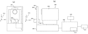
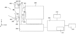
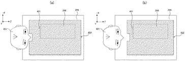
図2(b)は、第1の実施形態に係る眼科装置の側面図である。200は眼科装置、208は前眼画像および眼底の2次元像および断層像を取得するための測定光学系である光学ヘッド、207は光学ヘッドをXYZ方向に不図示のモータを用いて移動可能とした移動部であるステージ部である。206は後述の分光器を内蔵するベース部である。
(Body structure)
FIG. 2B is a side view of the ophthalmologic apparatus according to the first embodiment. 200 is an ophthalmologic apparatus, 208 is an optical head that is a measurement optical system for acquiring an anterior ocular image and a two-dimensional image and a tomographic image of the fundus, and 207 is movable in the XYZ directions using a motor (not shown). It is the stage part which is the moving part.
209はステージ部の制御部を兼ねるパソコンであり、ステージ部の制御とともに後述する断層画像の構成等を行う。211は被検者情報記憶部と検査セット記憶手段、走査制御手段を兼ね、断層撮像用のプログラムなどを記憶するハードディクである。210は表示部であるモニタであり、212はパソコンへの指示を行う入力部であり、具体的にはキーボードとマウスから構成される。203は顔受けであり、被検者のあごと額とを固定することで、被検者の眼の固定を促す。204は、被検者の額を受けるシリコンゴム部材である。(以下では額当てと呼ぶ)205は被検者の顎を受ける部材で、不図示のアクチュエータにて、Y軸方向に30mmのストロークで動作し、被検眼の高さを調整する。(以下では顎受けと呼ぶ)図2(a)は、第1実施形態に係る眼科装置の正面図である。先に説明した額受けシリコンゴム部材204の取り付け部の上側筐体内部にホール素子201が取り付けられている。顎を受ける部材205の内部にも、ホール素子202が取り付けられている。ホール素子201および202は、眼科検査装置200の内部に設置された不図示のCPU基板に接続されており、磁気を検知した場合に、検知する仕組みになっている。
A
なお、ここで述べた被検者の顎を受ける顎受け、あるいは額を受ける額受け(額当て)は本発明における装着部材の一態様であり、これらは少なくともその一方が用いられれば良い。また、これら装着部材は、眼科装置に装着されることにより、眼科装置の焦点を前眼部に対して移動させる作用を有する。 The chin rest for receiving the subject's chin or the forehead receiving the forehead (forehead rest) described here is one aspect of the mounting member in the present invention, and at least one of them may be used. In addition, these mounting members have an effect of moving the focal point of the ophthalmologic apparatus relative to the anterior eye portion by being mounted on the ophthalmologic apparatus.
(測定光学系および分光器の構成)
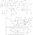
本実施例の測定光学系および分光器の構成について図3を用いて説明する。
まず、光学ヘッド208部の内部について説明する。被検眼301に対向して対物レンズ302が設置されている。332は前眼観察用レンズであり、不図示の対物レンズ鏡筒に内側に切られたフィルターネジに着脱可能となっており、前眼部を撮影する際のみに装着されるレンズである。対物レンズの光軸は第1ダイクロイックミラ303によって、前眼観察用光路331とOCTおよび眼底観察と内部固視灯用の光路334へ分岐される。そして、第2ダイクロイックミラ306によってOCT光学系の光路333、眼底観察と内部固視灯用の光路332に分岐される。
(Configuration of measurement optical system and spectrometer)
The configuration of the measurement optical system and the spectroscope of this example will be described with reference to FIG.
First, the inside of the
光路332はさらに第3ダイクロイックミラ310によって眼底観察用のCCD311および固視灯312への光路へと上記と同じく波長帯域ごとに分岐される。ここで308、309はレンズであり、308は固視灯および眼底観察用の焦点合わせのため不図示のモータによって駆動される。CCD311は不図示の眼底観察用照明光の波長、具体的には780nm付近に感度を持つものである。一方、固視灯312は可視光を発生して被検者の固視を促すものである。
The
光路331において304はレンズ、305は前眼観察用の赤外CCDである。このCCD305は不図示の前眼観察用の波長、具体的には970nm付近に感度を持つものである。
In the
光路333は前述の通りOCT光学系を成しており被検眼301の眼底の断層画像を撮像するためのものである。より具体的には断層画像を形成するための干渉信号を得るものである。314、315は光を眼底上で走査するためのXYスキャナである。316、317はレンズであり、そのうちレンズ316は光カプラ319に接続されているファイバ318から出射するOCT光源321からの光を被検眼301の眼底に焦点合わせするために不図示のモータによって駆動される。この焦点合わせによって被検眼301の眼底からの光は同時にファイバ318の先端に、スポット状に結像されて入射されることとなる。
The
次に、OCT光源321からの光路と参照光学系、分光器335の構成について説明する。
321はOCT光源、325はミラー、324は分散補償用ガラス、319は前述した光カプラ、318、320、322、326は光カプラに接続されて一体化しているシングルモードの光ファイバ、323はレンズ、335は分光器である。
Next, the configuration of the optical path from the OCT
321 is an OCT light source, 325 is a mirror, 324 is dispersion compensation glass, 319 is the optical coupler described above, 318, 320, 322, and 326 are connected to the optical coupler and integrated into a single mode optical fiber, 323 is a
これらの構成によってマイケルソン干渉系を構成している。OCT光源321から出射された光は光ファイバ320を通じ、光カプラ319を介して光ファイバ318側の測定光と光ファイバ322側の参照光とに分割される。
測定光は前述のOCT光学系光路を通じ、観察対象である被検眼301の眼底に照射され、網膜による反射や散乱により同じ光路を通じて光カプラ319に到達する。
The Michelson interference system is configured by these configurations. Light emitted from the OCT
The measurement light is irradiated on the fundus of the
光カプラ319によって、測定光と参照光は合波され干渉光となる。ここで、測定光の光路長と参照光の光路長がほぼ同一となったときに干渉を生じる。ミラー325は不図示のモータおよび駆動機構によって光軸方向に調整可能に保持され、被検眼301によって変わる測定光の光路長に参照光の光路長を合わせることが可能である。干渉光は光ファイバ326を介して分光器335に導かれる。
The measurement light and the reference light are combined by the
また336は光ファイバ318中に設けられた測定光側の偏光調整部である。337は光ファイバ322中に設けられた参照光側の偏光調整部である。これらの偏光調整部は光ファイバをループ状に引き回した部分を幾つか持ち、このループ状の部分をファイバの長手方向を中心として回動させることでファイバに捩じりを加えることで測定光と参照光の偏光状態を各々調整して合わせることが可能なものである。
分光器335はレンズ327、329、回折格子328、ラインセンサ330から構成される。
光ファイバ326から出射された干渉光はレンズ327を介して平行光となった後、回折格子328で分光され、レンズ329によってラインセンサ330に結像される。
The
The interference light emitted from the
次に、OCT光源321の周辺について説明する。OCT光源321は代表的な低コヒーレント光源であるSLD(Super Luminescent Diode)である。中心波長は855nm、波長バンド幅は約100nmである。ここで、バンド幅は、得られる断層画像の光軸方向の分解能に影響するため、重要なパラメータである。また、光源の種類は、ここではSLDを選択したが、低コヒーレント光が出射できればよく、ASE(Amplified Spontaneous Emission)等を用いることができる。中心波長は眼を測定することを鑑みると近赤外光が適する。また、中心波長は得られる断層画像の横方向の分解能に影響するため、なるべく短波長であることが望ましい。双方の理由から中心波長855nmとした。
Next, the periphery of the OCT
本実施例では干渉系としてマイケルソン干渉系を用いたが、マッハツェンダー干渉系を用いても良い。測定光と参照光との光量差に応じて光量差が大きい場合にはマッハツェンダー干渉系を、光量差が比較的小さい場合にはマイケルソン干渉計を用いることが望ましい。 In this embodiment, the Michelson interference system is used as the interference system, but a Mach-Zehnder interference system may be used. It is desirable to use a Mach-Zehnder interferometer when the light amount difference is large according to the light amount difference between the measurement light and the reference light, and a Michelson interferometer when the light amount difference is relatively small.
なお、以上に述べた光学系等において、被検者の眼底部の画像情報を得るための部材、およびこれらを動作させる構成であるパソコン209や後述するCPU等を、本発明のおける眼底情報取得手段として総称する。また、同様に、被検者の前眼部の画像情報を得るための部材、およびこれらを動作させる構成であるパソコン209や後述するCPU等を、本発明のおける前眼情報取得手段として総称する。
また、上述した光学系当の構成は、本発明において眼科装置において前眼部への光の照射と該光の前眼部からの反射光の受光を行う光学ヘッドとして機能する。
It should be noted that in the optical system described above, a member for obtaining image information of the fundus of the subject, a
In addition, the above-described configuration of the optical system functions as an optical head that performs irradiation of light to the anterior segment and reception of reflected light from the anterior segment in the ophthalmologic apparatus according to the present invention.
(断層画像の撮像方法)
眼科検査装置200を用いた断層画像の撮像方法について説明する。眼科装置200はXYスキャナ314、315を制御することで、被検眼301の所定部位の断層画像を撮像することができる。
(Tomographic imaging method)
A tomographic image capturing method using the
まず、図中X方向に測定光321のスキャンを行い、眼底におけるX方向の撮像範囲から所定の撮像本数の情報をラインセンサ330で撮像する。X方向のある位置で得られるラインセンサ330上の輝度分布を高速フーリエ変換(Fast Fourier Transform:FFT)し,FFTで得られた線状の輝度分布をモニタ210に示すために濃度あるいはカラー情報に変換したものをAスキャン画像と呼び、この複数のAスキャン画像を並べた2次元の画像をBスキャン画像と呼ぶ。1つのBスキャン画像を構築するための複数のAスキャン画像を撮像した後、Y方向のスキャン値を移動させて再びX方向のスキャンを行うことにより、複数のBスキャン画像を得る。
First, the
複数のBスキャン画像、あるいは複数のBスキャン画像から構築した3次元画像をモニタ210に表示することで検者が被検眼の診断に用いることができる。
上述では、X方向スキャンでBスキャン画像を得る例を示したが、これに限ることは無く、Y方向のスキャンでBスキャン画像を得てもよい。また、X方向、Y方向双方のスキャンによって任意のスキャンパターンにおいてBスキャン画像を得てもよい。
By displaying a plurality of B-scan images or a three-dimensional image constructed from a plurality of B-scan images on the
In the above description, an example in which a B-scan image is obtained by X-direction scanning has been described. Further, a B scan image may be obtained in an arbitrary scan pattern by scanning in both the X direction and the Y direction.
(検査セット)
検査セットについて説明する。スキャンパターンには多種の軌跡、例えば、ラインスキャンやクロスラインスキャン、複数ラインスキャン、サークルスキャン、ラジアルスキャン等がある。様々な病変に対して適切な検査を行うためには、これらの中から適切なスキャンパターンを決定する必要がある。また、病変によっては、複数のスキャンパターンを用いて検査することが必要である。
(Inspection set)
The inspection set will be described. There are various kinds of scan patterns, for example, line scan, cross line scan, multiple line scan, circle scan, radial scan and the like. In order to perform an appropriate examination on various lesions, it is necessary to determine an appropriate scan pattern from these. Further, depending on the lesion, it is necessary to inspect using a plurality of scan patterns.
スキャンパターン記憶部には、予め検査したい病変に適したスキャンパターンが記憶されている。例えば、黄斑部の疾患であれば、全体をスキャンする3Dスキャンや水平および垂直方向のクロススキャン、乳頭部の疾患で有れば、水平ラインスキャン、サークルスキャン等が記憶されている。 The scan pattern storage unit stores a scan pattern suitable for a lesion to be examined in advance. For example, a 3D scan for scanning the entire macular region, horizontal and vertical cross scans, a horizontal line scan, a circle scan, and the like are stored for a nipple disease.
このように、予め病変に適したスキャンパターンを予め用意しておくことで、様々な病変に対してもそれぞれに適した検査を行うことができ、かつ検者は用意された検査セットの中から適切な検査セットを選択するのみで良いため、検者の手間を減らし、スループットを向上させることができる。 In this way, by preparing scan patterns suitable for lesions in advance, it is possible to perform tests suitable for various lesions, and the examiner can select from the prepared test sets. Since it is only necessary to select an appropriate inspection set, the labor of the examiner can be reduced and the throughput can be improved.
(キャプチャ画面)
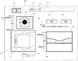
図1にキャプチャ画面を示す。
102は前眼観察用CCDによって得られた前眼観察画面、111は眼底観察用CCDによって得られた眼底2次元像表示画面、108は取得された断層画像を確認するための断層画像表示画面である。
101は被検眼の左右眼を切り替えるボタンであり、L、Rボタンを押すことにより、左右眼の初期位置に光学ヘッド208を移動する。
(Capture screen)
FIG. 1 shows a capture screen.
102 is an anterior eye observation screen obtained by the anterior eye observation CCD, 111 is a fundus two-dimensional image display screen obtained by the fundus observation CCD, and 108 is a tomographic image display screen for confirming the acquired tomographic image. is there.
115は検査セット選択画面であり、選択されている検査セットを表示する。検査セットを変更する際には、検者は114をクリックすることで、不図示のプルダウンメニューを表示させ、所望の検査セットを選択する。前期の不図示のプルダウンメニューの一つに、前眼撮影モードがある。前眼撮影モードが選択された場合の動作は後述する。また、走査パターン表示画面113には、現在選択されている検査セットで行うスキャンパターンの名称、例えば水平スキャン、垂直スキャン、クロススキャンなどを表示する。 Reference numeral 115 denotes an inspection set selection screen, which displays the selected inspection set. When changing the inspection set, the inspector clicks 114 to display a pull-down menu (not shown) and selects a desired inspection set. One of the pull-down menus not shown in the previous period is an anterior eye photography mode. The operation when the anterior eye photography mode is selected will be described later. The scan pattern display screen 113 displays the name of the scan pattern to be performed on the currently selected inspection set, for example, horizontal scan, vertical scan, cross scan, and the like.
前眼観察画面102上の任意の点をマウスでクリックすることで、その点を画面の中心にするよう光学ヘッド208を不図示のXYZテーブルにて移動させ、光学ヘッドと被検眼の位置合わせを行う。
106は開始ボタンであり、このボタンを押すことで二次元画像および断層像の取得が開始され、2次元像表示画面111および断層画像表示画面108に取得した被検眼像がリアルタイムで表示される。
By clicking an arbitrary point on the anterior
それぞれの画像の近傍に配置されているスライダは、調整を行うためのものである。スライダ104は被検眼に対する光学ヘッドのZ方向の位置を調整するもの、スライダ110はフォーカス調整を行うもの、スライダ109はコヒーレンスゲートの位置を調整するものである。フォーカス調整は、眼底に対する合焦調整を行うために、レンズ308および316を図示の方向に移動する調整である。コヒーレンスゲート調整は、断層画像が断層画像表示画面の所望の位置で観察されるために、ミラー325を図示の方向に移動する調整である。これらの調整操作により、検者は最適な撮像が行える状態を創出する。
107は撮像ボタンであり、各種調整が終了したときに、このボタンを押すことで所望の撮像が行われる。
A slider arranged in the vicinity of each image is used for adjustment. The slider 104 adjusts the position of the optical head in the Z direction with respect to the eye to be examined, the
図5は、前眼撮影のための装着部材を取り付けた眼科装置側面図である。401は対物レンズ鏡筒部である。402は、焦点位置を被検者406の前眼部へ合わせるための部材である。(以下では前記部材402をアタッチメント額当てと呼ぶ)材質はシリコンゴムで出来ている。405は磁石である。磁石405は、アタッチメント額当て402の内部に組み込まれており、額当て204にかぶせるように顔受け203に装着する。そして脱落しないように不図示の面ファスナーあるいは着脱機構を設けて、顔受け203から脱落しないようにする。額当て204にかぶせるように顔受け203に装着するとホール素子201が磁気に反応し、アタッチメント額当て402が本体へ装着されていることを眼科装置200の内部に設置された不図示のCPUが検知する。403は、焦点位置を被検者406の前眼部へ合わせるための部材である。(以下では前記部材403をアタッチメント顎当てと呼ぶ)材質はシリコンゴムで出来ている。404は磁石である。磁石406は、アタッチメント顎当て403の内部に組み込まれており、顎当て403に被せるように顎受け205に装着する。アタッチメント顎当て403を顎受け205に被せるとホール素子202が磁気に反応し、アタッチメント顎受けが顎受け部へ装着されていることを眼科検査装置200の内部に設置された不図示のCPUが検知する。501は前眼撮影用レンズ332が組み込まれた鏡筒である。従って、この場合には装着部材として、対物レンズの前に装着される光学部材も含まれる。対物レンズ鏡筒部401の不図示フィルターネジ部へねじ込んで眼科検査装置200へ装着している。502は磁石である。磁石502は、鏡筒501のフィルターネジ付近に組み込まれている。503はホール素子である。ホール素子503は、眼科装置200の内部に設置された不図示のCPUに電気的に接続されている。対物レンズ鏡筒部401の不図示フィルターネジ部へねじ込んで眼科検査装置200へ装着するとホール素子503が、磁石502に反応し、鏡筒501が眼科装置200に取り付けられたことを眼科検査装置200の内部に設置された不図示のCPUが検知する。以上に述べた前眼撮影用装着部材402、403、501の検知にホール素子の例を示したが、静電容量型の距離センサやスイッチ式のセンサで装着を検知してもよい。
FIG. 5 is a side view of an ophthalmologic apparatus to which a mounting member for anterior eye photography is attached.
なお、これら眼科装置に装着される装着部材の装着の有無を判定するためのホール素子等のセンサ、および当該センサから得られる信号より実際に装着の有無を判定するCPUあるいはパソコン209における判定用のモジュール領域を含め、本発明における判定手段として総称する。当該判定手段は、後述する撮影モード選択手段による前眼部撮影モードの選択の有無の判定も実行する。また、本発明の装着部材としては、測定光の光路における対物レンズの被検眼側に装着する光学部材等もその一態様として例示される。
It should be noted that a sensor such as a hall element for determining whether or not a mounting member to be mounted on these ophthalmic devices is mounted, and a CPU or
図6は、検査セット115を前眼撮影モードにセットした際のフローである。
S601では、撮影モード選択手段により、検査セット115を前眼撮影モードにセットする。当該前眼撮影モードの選択は、CPUあるいはパソコン209において前眼部の画像情報を得る前眼部撮影モードを選択する撮影モード選択手段として機能するモジュール領域により実行される。次にS602に遷移する。S602では、CPUにより、開始ボタン106が無効にされる。S603では、前述した判定手段が、鏡筒501が眼科装置200に装着されているかどうかを判断する。鏡筒501が装着されている場合はS604へ、鏡筒501が装着されていない場合はS609へ遷移する。S609では、表示制御手段によって制御された表示手段を構成する表示画面100の105へ、鏡筒501が装着されていない警告を表示しS603へ戻る。S604では、判定手段がアタッチメント額当て402が眼科装置200に装着されているかどうかを判断する。アタッチメント額当て402が装着されている場合はS605へ、アタッチメント額当て402が装着されていない場合はS610へ遷移する。S610では、表示制御手段により制御された表示画面100の105へ、アタッチメント額当て402が装着されていない警告を表示し、S604へ戻る。S605では、判定手段がアタッチメント顎当て403が顎受け205に装着されているかどうかを判断する。アタッチメント顎当て403が装着されている場合はS606へ、アタッチメント顎当て403が装着されていない場合はS611へ遷移する。S611では、表示手段が、表示画面100の105へ、アタッチメント顎当て403が装着されていない警告を表示し、S605へ戻る。S606では、CPUが開始ボタン106を有効にする。ここまで到達すると前眼観察撮影に関する装着部材が全て装着されているので、前眼撮影が間違いなくできるようになる。S607では、前眼撮影モード終了の判断が行われる。前眼撮影モード終了していない場合は、S603へ戻る。前眼撮影モード終了している場合は、S608へ遷移する。S608では、前眼撮影モードが終了する。
FIG. 6 is a flow when the examination set 115 is set to the anterior eye photography mode.
In S601, the examination set 115 is set to the anterior eye photography mode by the photography mode selection means. The selection of the anterior ocular photographing mode is executed by a module area functioning as an imaging mode selecting means for selecting an anterior ocular segment photographing mode for obtaining image information of the anterior ocular segment in the CPU or the
上述した警告の表示は、判定手段による判定結果に基づいて検者への報知が必要となる警告を行う警告手段として機能する。その際、前眼部撮影モードの選択の有無を示す表示と、装着部材の装着の有無とを示す表示のうちの少なくとも一方の表示形態を指定し、警告手段の一つとしても機能可能な表示手段にこれを指示する表示制御手段として機能するモジュール領域を、該制御手段に配することが好ましい。更にこの場合、判定手段が、前眼撮影モードが選択された状態で装着部材が眼科装置に装着されていないと判定した場合、あるいは、前眼部撮影モードが選択されていない状態で装着部材が眼科検査装置に装着されていると判定した場合、警告手段に検者への警告の報知を例えは表示画面100の105において行っている。しかし、前述した特定の警告手段による報知に関連する前述の表示形態を常にこの105に表示させておいても良い。
また、当該警告手段による警告の報知、あるいは後述する動作規制範囲の設定等は、判定手段の判定結果に基づいて行われる眼科装置の所定の動作に対応し、当該所定の動作はCPUあるいはパソコン209において制御手段として機能するモジュール領域により実行される。
なお、該判定手段は、前眼部撮影モードの選択と、眼科装置に対する所定の箇所への着脱可能な装着部材の装着と、のうちの少なくとも一方の有無の判定を行えば良く、この場合、制御手段は当該判定結果に基づいて所定の動作を行わせることとすれば良い。この場合所定の動作は、警告手段による報知が好ましい。また、本発明の一態様として、前眼部撮影モードの選択と、装着部材の該所定の箇所への装着とのうち一方が行われて他方が行われていない場合、他方が行われていないことを示す表示制御手段が指示する特定の表示形態によって表示手段に表示させても良い。更にこの場合、装着部材が装着されていないこと、或いは前眼部撮影モードが選択されていないこと、を表示制御手段が指示する特定の表示形態により、これを表示手段に表示させることが好ましい。
また、本発明は、その一態様として、測定光を照射した被検者の被検眼からの戻り光に基づいて該被検眼の画像を取得する眼科装置において、被検眼の前眼部の画像を取得する前眼部撮影モードを選択する撮影モード選択手段と、前眼部撮影モードが選択された場合、測定光の光路における対物レンズの被検眼側に前眼部撮影用レンズを挿入する制御手段とを配した構成も包含する。
The warning display described above functions as a warning unit that performs a warning that requires notification to the examiner based on the determination result of the determination unit. At that time, at least one of the display indicating whether or not the anterior ocular segment photographing mode is selected and the display indicating whether or not the mounting member is mounted is designated, and the display can also function as one of the warning means. It is preferable that a module area functioning as a display control means for instructing the control means is arranged in the control means. Furthermore, in this case, when the determination unit determines that the mounting member is not mounted on the ophthalmologic apparatus in a state where the anterior ocular photographing mode is selected, or the mounting member is in a state where the anterior ocular segment imaging mode is not selected. When it is determined that the ophthalmic examination apparatus is attached, the warning means notifies the examiner of the warning, for example, on the
Further, the warning notification by the warning means or the setting of the operation restriction range described later corresponds to a predetermined operation of the ophthalmologic apparatus performed based on the determination result of the determination means, and the predetermined operation is the CPU or the
The determination unit may determine whether or not at least one of the selection of the anterior ocular segment photographing mode and the attachment of a detachable attachment member to a predetermined location with respect to the ophthalmologic apparatus. The control means may perform a predetermined operation based on the determination result. In this case, the predetermined operation is preferably notified by a warning means. Moreover, as one aspect of the present invention, when one of the selection of the anterior ocular segment photographing mode and the mounting of the mounting member to the predetermined portion is performed and the other is not performed, the other is not performed. It may be displayed on the display means according to a specific display form instructed by the display control means. Furthermore, in this case, it is preferable that the display means display the specific display form in which the display control means indicates that the mounting member is not mounted or that the anterior segment imaging mode is not selected.
Further, according to one aspect of the present invention, in an ophthalmologic apparatus that acquires an image of the subject eye based on return light from the subject eye of the subject irradiated with the measurement light, an image of the anterior eye portion of the subject eye is obtained. An imaging mode selection unit that selects an anterior ocular segment imaging mode to be acquired, and a control unit that inserts an anterior ocular segment imaging lens on the eye side of the objective lens in the optical path of the measurement light when the anterior ocular segment imaging mode is selected A configuration in which is arranged is also included.
図7は、検査セット115を前眼撮影モード以外にセットした際のフローである。 FIG. 7 is a flow when the inspection set 115 is set to a mode other than the anterior eye photographing mode.
S701では、撮影モード選択手段が検査セット115を前眼撮影モード以外にセットする。次にS702に遷移する。S702では、CPUが開始ボタン106を無効にする。S703では、判定手段が、鏡筒501が眼科検査装置200に装着されているかどうかを判断する。鏡筒501が装着されている場合はS709へ、鏡筒501が装着されていない場合はS704へ遷移する。S709では、表示制御手段により、表示手段を構成する表示画面100の105へ、鏡筒501が装着されている警告を表示し、S703へ戻る。S704では、判定手段がアタッチメント額当て402が眼科装置200に装着されているかどうかを判断する。アタッチメント額当て402が装着されている場合はS710へ、アタッチメント額当て402が装着されていない場合はS705へ遷移する。S710では、表示手段が表示画面100の105へ、アタッチメント額当て402が装着されている警告を表示し、S704へ戻る。S705では、判定手段がアタッチメント顎当て403が顎受け205に装着されているかどうかを判断する。アタッチメント顎当て403が装着されている場合はS711へ、アタッチメント顎当て403が装着されていない場合はS705へ遷移する。S711では、表示手段が表示画面100の105へ、アタッチメント顎当て403が装着されている警告を表示する。S706では、CPUが開始ボタン106を有効にする。ここまで到達すると前眼観察撮影モードの装着部材が全て装着されていないので、前眼撮影モード以外が間違いなくできるようになる。S707では、判定手段が前眼撮影モード以外終了の判断をする。前眼撮影モード以外が終了していない場合は、S703へ戻る。前眼撮影モード以外が終了している場合は、S708へ遷移する。S708では、前眼撮影モード以外が終了する。
In S701, the imaging mode selection unit sets the examination set 115 to a mode other than the anterior eye imaging mode. Next, the process proceeds to S702. In S702, the CPU invalidates the
以上に述べたように、前眼撮影モードに切り替えると前眼撮影のための装着部材402、403、501が眼科装置200に装着されていないと開始ボタン106が有効にならない。また、前眼撮影モード以外では、前眼撮影のための装着部材402、403、501が眼科装置200に装着されていると、開始ボタン106が有効にならない。このために、前眼撮影モードのための装着部材の取り外しが間違いなくできるようになる。
As described above, when switching to the anterior eye photography mode, the
[第2の実施形態]
図面を参照して、本発明に係る第2の実施形態について説明する。
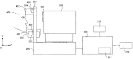
図4は、第2の実施形態に係る眼科装置の側面図である。第1の実施形態と、測定光学系および分光器の構成、断層画像の撮像方法、検査セット、キャプチャ画面は同じである。本体構成については、光学ヘッド208のZ軸の移動量を20mm拡大している。このため、第1の実施形態で示した鏡筒501を装着しなくても、アタッチメント額当て402、アタッチメント顎当て403の装着のみで、前眼撮影が可能な仕様に構成されていることのみが異なる。動作フローについては、図6のS603、図7のS703判断部とそれの分岐S609、S709が無いのが異なるだけである。
以上に述べたように、前眼撮影モードに切り替えると前眼撮影のための装着部材402、403が眼科装置200に装着されていないと開始ボタン106が有効にならない。また、前眼撮影モード以外では、前眼撮影のための装着部材402、403が眼科装置200に装着されていると、開始ボタン106が有効にならない。このために、前眼撮影モードのための装着部材の取り外しが間違いなくできるようになる。また、この例では鏡筒501が不要な構成を示しているが、前眼撮影モード時に必要な装着部材が1つの場合でも、同様に実施できるものであることを付け加えておく。
[Second Embodiment]
A second embodiment according to the present invention will be described with reference to the drawings.
FIG. 4 is a side view of the ophthalmologic apparatus according to the second embodiment. The configuration of the measurement optical system and the spectroscope, the tomographic image capturing method, the inspection set, and the capture screen are the same as in the first embodiment. As for the main body configuration, the amount of movement of the
As described above, when switching to the anterior eye photography mode, the
[第3の実施形態]
図面を参照して、本発明に係る第3の実施形態について説明する。
図8は、第3の実施形態に係る眼科装置の本体上面図である。この図面は説明の便宜上、顔受け203を省略している。構成については、第1の実施形態で示したフローチャートにあらたな動作フロー追加された点のみがことなる。このフローの説明は後述する。
[Third Embodiment]
A third embodiment according to the present invention will be described with reference to the drawings.
FIG. 8 is a top view of the main body of the ophthalmologic apparatus according to the third embodiment. In this drawing, the
801は被検者である。802は、光学ヘッド部208の動作規制範囲内である。この動作規制範囲内802で光学ヘッド部208を動作させることで、被検者と光学ヘッドの距離を適切に保っている。
光学ヘッド208の移動は、前記光学ヘッド208を固定した不図示のXYZテーブルを不図示のステッピングモータと送りねじで各軸を移動させ、各軸の原点は不図示の原点検出スイッチにて位置を把握するようにしている。
Reference numeral 801 denotes a subject. Reference numeral 802 denotes an operation regulation range of the
The
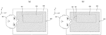
図8(a)は、眼底を撮影している図面である。図8(b)は、前眼を撮影するために、鏡筒501を対物鏡筒のフィルターネジにねじ込んで装着している図である。この場合は、鏡筒501の体積分だけ光学ヘッド208の移動量を変更し、光学ヘッド208と鏡筒501までを動作規制範囲内802の中におさめている。
FIG. 8A is a drawing in which the fundus is imaged. FIG. 8B is a diagram in which the lens barrel 501 is screwed into the filter screw of the objective lens barrel in order to photograph the anterior eye. In this case, the movement amount of the
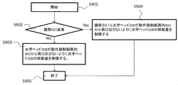
図9は動作のフロー図である。S901で、CPUによるフロー開始の指示がなされる。S902で、判定手段が鏡筒501が光学ヘッド208の対物鏡筒部401に装着されているか判断する。鏡筒501が装着されている場合はS904へ、鏡筒501が装着されていない場合はS903へ遷移する。S904では、制御手段が、鏡筒501と光学ヘッド208が動作規制範囲内802から飛び出さないように光学ヘッド208の移動量を制限する。
S903では、制御手段が、光学ヘッド208が動作規制範囲内802から飛び出さないように光学ヘッド208の移動量を制限する。S905はフローの終了である。
最後に、上記の光学ヘッド208の移動手段は、ステッピングモータの構成で説明されているが、鏡筒501の装着を検知して、光学ヘッド208の移動手段が制限できれば、どのような手段でもよい。
FIG. 9 is a flowchart of the operation. In step S901, the CPU issues a flow start instruction. In step S <b> 902, the determination unit determines whether the lens barrel 501 is attached to the objective
In step S903, the control unit limits the movement amount of the
Finally, the moving means of the
以上に述べたように、前眼装着部材が装着された場合でも、光学ヘッドの動作規制範囲を変更することで、被検者と装置の距離を適切に保つことで、操作性が向上する。なお、これら光学ヘッドの動作規制範囲の設定は、上述したフローを実行するCPUあるいはパソコン209において光学ヘッドの動作規制範囲を変更する範囲変更手段として機能するモジュール領域により実行される。また、本実施の形態において、前眼部撮影モードが選択されている、あるいは装着部材が眼科装置に装着されている、少なくとも何れかの状態であると判定手段が判定した際に制御手段が行う所定の動作は、この光学ヘッドの動作規制範囲を変更することとなる。
As described above, even when the anterior eye mounting member is mounted, operability is improved by appropriately maintaining the distance between the subject and the apparatus by changing the operation restriction range of the optical head. The setting of the operation restriction range of the optical head is executed by a module area that functions as a range changing unit that changes the operation restriction range of the optical head in the CPU or the
[第4の実施形態]
図面を参照して、本発明の第4の実施形態について述べる。本実施形態は第3の実施形態で述べた眼科装置の構成と同じ構成であり、図10に示す動作フローにおいて異なっている。
[Fourth Embodiment]
A fourth embodiment of the present invention will be described with reference to the drawings. This embodiment has the same configuration as that of the ophthalmologic apparatus described in the third embodiment, and differs in the operation flow shown in FIG.
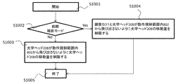
当該フローにおいて、S1001でCPU(制御手段)によりフローが開始される。S1002で、判定手段が、前眼撮影モードが選択されているかを判断する。前眼撮影モードが選択されている場合はS1004へ、前眼撮影モードが選択されていない場合はS1003へ遷移する。S1004では、制御手段が、鏡筒501と光学ヘッド208が動作規制範囲内802から飛び出さないように光学ヘッド208の移動量を制限する。
S1003では、光学ヘッド208が動作規制範囲内802から飛び出さないように光学ヘッド208の移動量を制限する。S1005はフローの終了である。
In this flow, the flow is started by the CPU (control means) in S1001. In step S1002, the determination unit determines whether the anterior ocular photographing mode is selected. If the anterior eye photography mode is selected, the process proceeds to S1004. If the anterior eye photography mode is not selected, the process proceeds to S1003. In step S1004, the control unit limits the movement amount of the
In S1003, the movement amount of the
[第5の実施形態]
図面を参照して、本発明の第5の実施形態について説明する。
第5の実施形態に係る眼科装置の構成は、第3の実施形態に係る眼科装置の鏡筒501に相当する不図示のレンズが、図3のOCT光学系の光路333内に、不図示の挿入脱出機構にて、挿入脱出されることと、その挿入脱出のフロー部が異なる。そして、図3のOCT光学系の光路333内に鏡筒501に相当する不図示のレンズが挿入されると、被検者までのワーキングディスタンス(被検眼の角膜頂点と対物レンズの距離)が、眼底撮影時より10mm長くなることも異なる。(以下では、前記距離を差分距離と呼ぶ。)
前記のOCT光学系の光路333への鏡筒501に相当する不図示のレンズの挿入脱出フローも、検査セット115が前眼撮影モードに切り替えられると、前記のOCT光学系の光路333内に前記不図示のレンズを挿入し、検査セット115が前眼撮影モード以外に設定されると、前記のOCT光学系の光路333内に前記不図示のレンズを脱出させるだけなので、フロー図は省略する。
[Fifth Embodiment]
The fifth embodiment of the present invention will be described with reference to the drawings.
The configuration of the ophthalmologic apparatus according to the fifth embodiment is such that a lens (not shown) corresponding to the lens barrel 501 of the ophthalmologic apparatus according to the third embodiment is not shown in the
An insertion / extraction flow of a lens (not shown) corresponding to the lens barrel 501 into the
上記の構成にて、検査セット115が前眼撮影モードにセットされると、光学ヘッド部208の動作範囲を差分距離だけ変更する。図11(a)は、前眼撮影モード以外の光学ヘッド部208の動作範囲802で、図11(b)は、前眼撮影モードの光学ヘッド部208の動作範囲802である。上記の例では、装置本体内部の光路に光学部材を挿脱させる機構での光学ヘッド部208の動作範囲変更例を示した。
以上に述べたように、前眼装着部材が装着された場合でも、光学ヘッドの動作規制範囲を変更することで、被検者と装置の距離を適切に保つことで、操作性が向上する
With the above configuration, when the examination set 115 is set to the anterior eye photographing mode, the operation range of the
As described above, even when the anterior eye mounting member is mounted, the operability is improved by appropriately maintaining the distance between the subject and the apparatus by changing the operation restriction range of the optical head.
[第6の実施形態]
図面を参照して、本発明に係る第6の実施形態について説明する。第6の実施形態に係る眼科装置の構成は、第3の実施形態に係る眼科装置と同じ構成で、後述する図12に示す。フローのみが異なる。S1201では、制御手段によりフローの開始が指示される。S1202では、判定手段が鏡筒501の装着を判断する。鏡筒501が装着されている場合は、S1204へ、鏡筒501が装着されていない場合は、S1203へ遷移する。S1204では、制御手段が、光学ヘッド208を+Z方向のリミットポイントまで移動させる。そして、S1203へ遷移する。S1203では、制御手段による検査を開始する指示が為される。
[Sixth Embodiment]
A sixth embodiment according to the present invention will be described with reference to the drawings. The configuration of the ophthalmologic apparatus according to the sixth embodiment is the same as that of the ophthalmologic apparatus according to the third embodiment, and is shown in FIG. Only the flow is different. In S1201, the control unit instructs the start of the flow. In S1202, the determination unit determines whether the lens barrel 501 is attached. If the lens barrel 501 is attached, the process proceeds to S1204. If the lens barrel 501 is not attached, the process proceeds to S1203. In step S1204, the control unit moves the
以上に示したように、前眼撮影に関連した装着部材の装着を検知した場合は、光学ヘッドを被検者から遠ざけることで、被検者へ圧迫感を感じさせないようにしている。さらには、不意の誤操作を避けられる。
即ち、本実施形態においては、装着部材は前眼アタッチメントレンズ(前眼撮影用レンズ332)が例示される。また、前眼撮影モードが選択されている、と共に前眼アタッチメントレンズが眼科装置に装着されている、と判定手段が判定した場合に、制御手段は所定の動作として、光学ヘッド移動手段によって光学ヘッドを被検者から最も離れた位置に移動させる。なお、ここで述べる光学ヘッドは、前述した眼科装置において前眼部への光の照射と前眼部からの反射光の受光とを行う構成に対応し、光学ヘッド移動手段は前述した該光学ヘッドを特にZ方向に移動させる構成に対応する。
As described above, when the attachment of the attachment member related to anterior eye photography is detected, the optical head is moved away from the subject so that the subject does not feel a sense of pressure. Furthermore, it is possible to avoid an unexpected erroneous operation.
That is, in this embodiment, the mounting member is exemplified by an anterior eye attachment lens (anterior eye photographing lens 332). Further, when the determination unit determines that the anterior eye photographing mode is selected and the anterior eye attachment lens is attached to the ophthalmologic apparatus, the control unit performs the optical head by the optical head moving unit as a predetermined operation. Is moved to the position farthest from the subject. The optical head described here corresponds to a configuration in which the above-described ophthalmic apparatus performs irradiation of light to the anterior eye portion and reception of reflected light from the anterior eye portion, and the optical head moving means is the optical head described above. In particular, this corresponds to a configuration in which the is moved in the Z direction.
[第7の実施形態]
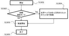
図面を参照して、本発明に係る第7の実施形態について説明する。第7の実施形態に係る眼科装置の構成は、第3の実施形態に係る眼科装置と同じ構成で、後述する図13に示す。フローのみが異なる。S1301では、プログラムの開始。S1302では、検査セット115が前眼撮影モードに設定されているか否かを判断する。鏡筒501が装着されている場合は、S1304へ、鏡筒501が装着されていない場合は、S1303へ遷移する。S1304では、光学ヘッド208を+Z方向のリミットポイントまで移動させる。そして、S1303へ遷移する。S1303では、検査を開始する。
[Seventh Embodiment]
A seventh embodiment according to the present invention will be described with reference to the drawings. The configuration of the ophthalmologic apparatus according to the seventh embodiment is the same as that of the ophthalmologic apparatus according to the third embodiment, and is shown in FIG. Only the flow is different. In S1301, the program starts. In S1302, it is determined whether or not the examination set 115 is set to the anterior eye photography mode. If the lens barrel 501 is attached, the process proceeds to S1304. If the lens barrel 501 is not attached, the process proceeds to S1303. In S1304, the
以上に示したように、前眼撮影に関連した装着部材の装着を検知した場合は、光学ヘッドを被検者から遠ざけることで、被検者へ圧迫感を感じさせないようにしている。さらには、不意の誤操作を避けられる。 As described above, when the attachment of the attachment member related to anterior eye photography is detected, the optical head is moved away from the subject so that the subject does not feel a sense of pressure. Furthermore, it is possible to avoid an unexpected erroneous operation.
[その他の実施例]
また、本発明は、以下の処理を実行することによっても実現される。即ち、上述した実施形態の機能を実現するソフトウェア(プログラム)を、ネットワーク又は各種記憶媒体を介してシステム或いは装置に供給し、そのシステム或いは装置のコンピュータ(またはCPUやMPU等)がプログラムを読み出して実行する処理である。
[Other Examples]
The present invention can also be realized by executing the following processing. That is, software (program) that realizes the functions of the above-described embodiments is supplied to a system or apparatus via a network or various storage media, and a computer (or CPU, MPU, or the like) of the system or apparatus reads the program. It is a process to be executed.
本発明に係る眼科装置に対して以上の構成を配することにより、前眼部撮影モードに切り替えた際に、前眼撮影のための装着物の装着忘れが認識できる、前眼部撮影モード以外のモードに遷移した際に前眼撮影のための装着物が装着されていることが認識できる、あるいは前眼撮影モードに切り替わると、動作の規制範囲が切り替えられるので、撮影の動作が普段通りにできる、さらには前眼撮影モードに切り替わると、装置を被検者から最も遠ざけるので、誤操作を避けられる、といった効果が得られる。 By arranging the above configuration for the ophthalmologic apparatus according to the present invention, when switching to the anterior ocular segment imaging mode, it is possible to recognize forgetting to attach an attachment for anterior ocular imaging other than the anterior ocular segment imaging mode. When you switch to this mode, you can recognize that an object for anterior eye photography is attached, or when you switch to the anterior eye photography mode, the restricted range of operation can be switched, so the photography operation will be normal In addition, when switching to the anterior eye photography mode, the apparatus is moved farthest from the subject, so that an effect of avoiding an erroneous operation can be obtained.
100 表示画面
102 前眼観察画面
108 断層画像表示画面
111 2次元像表示画面
113 走査パターン表示画面
200 眼科装置
207 ステージ部
208 光学ヘッド
209 パソコン
210 表示部
203 顔受け
204 額当て
205 顎受け
301 被検眼
332 前眼観察用レンズ
401 レンズ鏡筒
402 額当て
403 顎当て
501 鏡筒
DESCRIPTION OF
Claims (9)
前記光学系を用いて前記被検眼の前眼部を撮影する前眼部撮影モード、または前記光学系を用いて前記被検眼の眼底を撮影する眼底撮影モードを選択する撮影モード選択手段と、
前記光学系を含む光学部を前記被検眼に対して移動する移動手段と、
前記光学系の光路に配置された対物レンズと、
前記対物レンズに対して前記被検眼とは反対側の光路に挿脱可能な前眼部撮影用レンズ
と、
前記前眼部撮影モードが選択された場合に、前記対物レンズに対して前記被検眼とは反対側の光路に前記前眼部撮影用レンズを挿入し、前記光学部の移動可能な範囲を前記眼底撮影モードが選択された場合における移動可能な範囲よりも狭い範囲に変更する範囲変更手段と、を有することを特徴とする眼科装置。 In an ophthalmologic apparatus equipped with an optical system for acquiring an image of an eye to be examined,
An imaging mode selection means for selecting an anterior ocular segment imaging mode for imaging the anterior ocular segment of the eye to be examined using the optical system, or a fundus imaging mode for imaging the fundus of the eye to be examined using the optical system;
Moving means for moving an optical unit including the optical system with respect to the eye to be examined;
An objective lens disposed in the optical path of the optical system;
An anterior ocular segment imaging lens that can be inserted into and removed from the optical path opposite to the subject eye with respect to the objective lens;
When the anterior segment imaging mode is selected, the anterior segment imaging lens is inserted into the optical path opposite to the eye to be examined with respect to the objective lens, and the movable range of the optical unit is An ophthalmologic apparatus comprising: range changing means for changing to a range narrower than a movable range when the fundus photographing mode is selected.
前記撮影モード選択手段により前記前眼部撮影モードが選択された場合において前記判定手段の判定結果に基づいて前記被検眼の画像の取得指示を無効とするか否かを判断する取得指示制御手段、
を備えることを特徴とする請求項5記載の眼科装置。
An acquisition instruction control means for determining whether or not to invalidate an acquisition instruction for the image of the eye to be examined based on a determination result of the determination means when the anterior ocular segment imaging mode is selected by the imaging mode selection means;
The ophthalmologic apparatus according to claim 5, comprising:
前記光学系を用いて前記被検眼の前眼部を撮影する前眼部撮影モード、または前記光学系を用いて前記被検眼の眼底を撮影する眼底撮影モードを選択する撮影モード選択工程と、
前記前眼部撮影モードが選択された場合に、前記対物レンズに対して前記被検眼とは反対側の光路に挿脱可能な前眼部撮影用レンズを挿入し、前記光学系の移動可能な範囲を前記眼底撮影モードが選択された場合における移動可能な範囲よりも狭い範囲に変更する範囲変更工程と、を有することを特徴とする眼科装置の制御方法。 In a method for controlling an ophthalmologic apparatus having an objective lens and an optical system for acquiring an image of an eye to be examined,
An imaging mode selection step of selecting an anterior ocular segment imaging mode for imaging the anterior ocular segment of the eye to be examined using the optical system, or a fundus imaging mode for imaging the fundus of the eye to be examined using the optical system;
When the anterior ocular segment imaging mode is selected, an anterior ocular segment imaging lens is inserted into the optical path opposite to the subject eye with respect to the objective lens, and the optical system is movable And a range changing step for changing the range to a range narrower than a movable range when the fundus photographing mode is selected.
Priority Applications (1)
| Application Number | Priority Date | Filing Date | Title |
|---|---|---|---|
| JP2013095585A JP5777657B2 (en) | 2013-04-30 | 2013-04-30 | Ophthalmic equipment |
Applications Claiming Priority (1)
| Application Number | Priority Date | Filing Date | Title |
|---|---|---|---|
| JP2013095585A JP5777657B2 (en) | 2013-04-30 | 2013-04-30 | Ophthalmic equipment |
Related Parent Applications (1)
| Application Number | Title | Priority Date | Filing Date |
|---|---|---|---|
| JP2012014648A Division JP5319799B2 (en) | 2012-01-26 | 2012-01-26 | Ophthalmic apparatus, control method thereof, and program |
Publications (2)
| Publication Number | Publication Date |
|---|---|
| JP2013154222A JP2013154222A (en) | 2013-08-15 |
| JP5777657B2 true JP5777657B2 (en) | 2015-09-09 |
Family
ID=49049979
Family Applications (1)
| Application Number | Title | Priority Date | Filing Date |
|---|---|---|---|
| JP2013095585A Expired - Fee Related JP5777657B2 (en) | 2013-04-30 | 2013-04-30 | Ophthalmic equipment |
Country Status (1)
| Country | Link |
|---|---|
| JP (1) | JP5777657B2 (en) |
Families Citing this family (2)
| Publication number | Priority date | Publication date | Assignee | Title |
|---|---|---|---|---|
| JP2016002381A (en) * | 2014-06-18 | 2016-01-12 | キヤノン株式会社 | Imaging apparatus and imaging method |
| JP6600931B2 (en) * | 2014-07-08 | 2019-11-06 | 株式会社ニデック | Ophthalmic imaging equipment |
Family Cites Families (3)
| Publication number | Priority date | Publication date | Assignee | Title |
|---|---|---|---|---|
| JP5328517B2 (en) * | 2009-06-26 | 2013-10-30 | 株式会社ニデック | Fundus photographing device |
| JP5545629B2 (en) * | 2010-01-21 | 2014-07-09 | 株式会社ニデック | Ophthalmic imaging equipment |
| JP5766468B2 (en) * | 2011-03-04 | 2015-08-19 | 株式会社トーメーコーポレーション | Ophthalmic equipment |
-
2013
- 2013-04-30 JP JP2013095585A patent/JP5777657B2/en not_active Expired - Fee Related
Also Published As
| Publication number | Publication date |
|---|---|
| JP2013154222A (en) | 2013-08-15 |
Similar Documents
| Publication | Publication Date | Title |
|---|---|---|
| JP5319799B2 (en) | Ophthalmic apparatus, control method thereof, and program | |
| JP6009935B2 (en) | Ophthalmic equipment | |
| JP6021384B2 (en) | Optical coherence tomography apparatus and control method | |
| JP5210442B1 (en) | Optical tomographic imaging apparatus and control method | |
| JP5210443B1 (en) | Optical tomographic imaging apparatus and control method | |
| JP6566541B2 (en) | Ophthalmic equipment | |
| JP6498398B2 (en) | Ophthalmic equipment | |
| JP2010181172A (en) | Optical image measuring device | |
| US9326679B2 (en) | Medical system | |
| JP6388440B2 (en) | Ophthalmic equipment | |
| JP2013212172A (en) | Optical coherence tomography imaging device, and method for controlling the same | |
| JP6184113B2 (en) | Optical tomographic imaging apparatus and control method thereof | |
| JP6188339B2 (en) | Optical tomographic imaging apparatus and control method thereof | |
| JP5777657B2 (en) | Ophthalmic equipment | |
| US9538913B2 (en) | Ophthalmic system | |
| JP6057619B2 (en) | Ophthalmic apparatus and method for controlling ophthalmic apparatus | |
| JP2014140542A (en) | Ophthalmological observation device | |
| JP5988883B2 (en) | Image processing apparatus and image processing method | |
| JP6311045B2 (en) | Ophthalmic observation device | |
| JP5936893B2 (en) | Optical image measuring device and polarization controller | |
| JP6308723B2 (en) | CONTROL DEVICE, ITS OPERATION METHOD, AND PROGRAM | |
| JP6701250B2 (en) | Ophthalmic photographing apparatus, control method thereof, and program | |
| JP6869793B2 (en) | Ophthalmic devices, their control methods, and programs | |
| JP5766225B2 (en) | Optical tomographic imaging apparatus and control method | |
| JP2016123481A (en) | Ophthalmologic apparatus, ophthalmologic system, and ophthalmologic apparatus control method |
Legal Events
| Date | Code | Title | Description |
|---|---|---|---|
| A621 | Written request for application examination |
Free format text: JAPANESE INTERMEDIATE CODE: A621 Effective date: 20130523 |
|
| RD05 | Notification of revocation of power of attorney |
Free format text: JAPANESE INTERMEDIATE CODE: A7425 Effective date: 20130701 |
|
| A977 | Report on retrieval |
Free format text: JAPANESE INTERMEDIATE CODE: A971007 Effective date: 20140421 |
|
| A131 | Notification of reasons for refusal |
Free format text: JAPANESE INTERMEDIATE CODE: A131 Effective date: 20140513 |
|
| A521 | Request for written amendment filed |
Free format text: JAPANESE INTERMEDIATE CODE: A523 Effective date: 20140710 |
|
| A131 | Notification of reasons for refusal |
Free format text: JAPANESE INTERMEDIATE CODE: A131 Effective date: 20141127 |
|
| A521 | Request for written amendment filed |
Free format text: JAPANESE INTERMEDIATE CODE: A523 Effective date: 20150120 |
|
| TRDD | Decision of grant or rejection written | ||
| A01 | Written decision to grant a patent or to grant a registration (utility model) |
Free format text: JAPANESE INTERMEDIATE CODE: A01 Effective date: 20150609 |
|
| A61 | First payment of annual fees (during grant procedure) |
Free format text: JAPANESE INTERMEDIATE CODE: A61 Effective date: 20150707 |
|
| R151 | Written notification of patent or utility model registration |
Ref document number: 5777657 Country of ref document: JP Free format text: JAPANESE INTERMEDIATE CODE: R151 |
|
| LAPS | Cancellation because of no payment of annual fees |