JP5776891B2 - Lighting device - Google Patents
Lighting device Download PDFInfo
- Publication number
- JP5776891B2 JP5776891B2 JP2011147048A JP2011147048A JP5776891B2 JP 5776891 B2 JP5776891 B2 JP 5776891B2 JP 2011147048 A JP2011147048 A JP 2011147048A JP 2011147048 A JP2011147048 A JP 2011147048A JP 5776891 B2 JP5776891 B2 JP 5776891B2
- Authority
- JP
- Japan
- Prior art keywords
- light source
- pattern
- illuminance correction
- mode
- lighting
- Prior art date
- Legal status (The legal status is an assumption and is not a legal conclusion. Google has not performed a legal analysis and makes no representation as to the accuracy of the status listed.)
- Active
Links
Images


Classifications
-
- H—ELECTRICITY
- H05—ELECTRIC TECHNIQUES NOT OTHERWISE PROVIDED FOR
- H05B—ELECTRIC HEATING; ELECTRIC LIGHT SOURCES NOT OTHERWISE PROVIDED FOR; CIRCUIT ARRANGEMENTS FOR ELECTRIC LIGHT SOURCES, IN GENERAL
- H05B45/00—Circuit arrangements for operating light-emitting diodes [LED]
- H05B45/10—Controlling the intensity of the light
-
- H—ELECTRICITY
- H05—ELECTRIC TECHNIQUES NOT OTHERWISE PROVIDED FOR
- H05B—ELECTRIC HEATING; ELECTRIC LIGHT SOURCES NOT OTHERWISE PROVIDED FOR; CIRCUIT ARRANGEMENTS FOR ELECTRIC LIGHT SOURCES, IN GENERAL
- H05B47/00—Circuit arrangements for operating light sources in general, i.e. where the type of light source is not relevant
- H05B47/10—Controlling the light source
- H05B47/175—Controlling the light source by remote control
- H05B47/185—Controlling the light source by remote control via power line carrier transmission
Landscapes
- Circuit Arrangement For Electric Light Sources In General (AREA)
Description
本発明の実施形態は、初期照度補正機能を有する照明装置に関する。 Embodiments described herein relate generally to a lighting device having an initial illuminance correction function.
一般に、例えば放電ランプやLED素子などの光源は、使用開始時の明るさが最も明るく、点灯時間の累積とともに明るさが徐々に低下していく。そこで、光源の使用開始時の明るさを抑えることにより、光源の使用開始時から寿命末期までの明るさを略一定にするとともに、省電力を図るようにした初期照度補正機能を有する照明装置がある。 In general, for example, a light source such as a discharge lamp or an LED element has the brightest brightness at the start of use, and the brightness gradually decreases as the lighting time accumulates. Therefore, by suppressing the brightness at the start of use of the light source, the lighting device having an initial illuminance correction function that makes the brightness from the start of use of the light source to the end of the life substantially constant and saves power. is there.
このような照明装置では、光源の累積点灯時間に応じた初期照度補正をするか、初期照度補正をしないかが予め設定されて設置されている。また、照明装置の使用状況などから、初期照度補正を行う設定では明るさが不足するような場合、初期照度補正をしない設定に切り換えられる。 In such an illuminating device, whether to perform initial illuminance correction according to the cumulative lighting time of the light source or not to perform initial illuminance correction is set in advance. Further, when the brightness is insufficient in the setting for performing the initial illuminance correction due to the usage status of the lighting device, the setting can be switched to the setting for not performing the initial illuminance correction.
従来、調光器を備えた照明装置の場合に、調光器の特定の操作により、初期照度補正を解除するようにしたものがあるが、調光器を備えない照明装置の場合には初期照度補正の解除が簡単にはできない。 Conventionally, in the case of a lighting device equipped with a dimmer, there is one in which the initial illumination correction is canceled by a specific operation of the dimmer. The illumination correction cannot be canceled easily.
従来の照明装置では、調光器を備えない場合には初期照度補正の解除が簡単にはできず、また、初期照度補正をする、しないを指定して設定することはできなかった。 In the conventional lighting device, when the dimmer is not provided, the cancellation of the initial illuminance correction cannot be easily performed, and the initial illuminance correction cannot be specified and set.
本発明が解決しようとする課題は、初期照度補正をする、しないを簡単に設定できるとともに、初期照度補正をする、しないを指定して設定できる照明装置を提供することである。 The problem to be solved by the present invention is to provide an illumination device that can easily set whether or not to perform initial illuminance correction, and can specify and set whether or not to perform initial illuminance correction.
実施形態の照明装置は、外部からの電源で光源を点灯させる点灯回路、光源の累積点灯時間を記憶する累積点灯時間記憶部、および設定されたモードで点灯回路を制御する制御回路を備える。制御回路は、外部からの電源がオンされる時間に基づくパターンが所定の初期照度補正設定パターンであると、光源の累積点灯時間に応じた初期照度補正をする初期照度補正モードに設定する。制御回路は、外部からの電源がオンされる時間に基づくパターンが所定の通常設定パターンであると、初期照度補正をしない通常モードに設定する。 The illumination device according to the embodiment includes a lighting circuit that turns on a light source with an external power source, a cumulative lighting time storage unit that stores a cumulative lighting time of the light source, and a control circuit that controls the lighting circuit in a set mode. Control circuitry, the pattern based on the time the power supply from the outside is on-is a predetermined initial illuminance correction setting pattern is set to the initial illuminance correction mode to the initial illuminance correction in accordance with the accumulated lighting time of the light source. Control circuitry, the pattern based on the time the power supply from the outside is on-is in a predetermined normal setting pattern is set to the normal mode without the initial illuminance correction.
本発明によれば、照明装置の電源をオンオフすることにより初期照度補正モードまたは初期照度補正を行わない通常モードを簡単に設定することができるとともに、初期照度補正モードを設定するか通常モードを設定するかに応じて、初期照度補正設定パターンまたは通常設定パターンを選択して照明装置の電源をオンオフすることにより、初期照度補正モードまたは通常モードを指定して設定することができる。 According to the present invention, it is possible to easily set the initial illuminance correction mode or the normal mode in which the initial illuminance correction is not performed by turning on / off the power of the lighting device, and set the initial illuminance correction mode or the normal mode. Depending on whether or not, the initial illuminance correction mode or the normal mode can be designated and set by selecting the initial illuminance correction setting pattern or the normal setting pattern and turning on / off the power of the lighting device.
以下、一実施形態を、図面を参照して説明する。 Hereinafter, an embodiment will be described with reference to the drawings.
図1に示すように、照明装置10は、光源11、およびこの光源11を点灯させる点灯ユニット12を備えている。照明装置10には、壁スイッチなどのスイッチ13のオンによって電源として商用交流電源Eが供給される。スイッチ13には、1つの照明装置10が接続されていてもよいし、複数の照明装置10が接続されていてもよい。
As shown in FIG. 1, the
光源11は、例えば、複数のLED素子15を備えている。この光源11は、例えば、両端に口金を有する直管形ランプ形態、ねじ口金を備えた電球形形態、GX形口金を備えたフラット形ランプ形態などのいずれの形態でもよい。さらに、光源11は、照明装置10に対して着脱可能でもよいし、照明装置10に一体化されていてもよい。そして、照明装置10の場合、一般に、寿命が40000時間程度で、初期の光束に対する寿命末期時の光束の減退が70〜80%程度となっている。
The light source 11 includes, for example, a plurality of
点灯ユニット12は、商用交流電源Eから交流電力を整流および平滑し、チョッパ回路のスイッチング素子のスイッチング動作により所定の直流電力に変換して光源11に出力するAC/DCコンバータである点灯回路17、およびこの点灯回路17のスイッチング素子のオンオフを制御する制御回路18を有している。
The
点灯回路17の電源入力側には電源オンオフを監視する電源監視回路19が接続され、電源オン時に電源監視回路19から制御回路18に電源オン信号を出力する。
A power
点灯回路17の直流電力出力側には負荷検出回路20が接続され、点灯ユニット12に光源11が接続されているときに負荷検出回路20から制御回路18に負荷検出信号を出力する。
A
制御回路18は、電源監視回路19からの電源オン信号を入力している間に計時するタイマ21の機能を備えている。制御回路18には、電源監視回路19からの電源オン信号を入力している間にタイマ21でカウントされる時間を、光源11の累積点灯時間として記憶する累積点灯時間記憶部としての記憶部22が接続されている。記憶部22は、電源オフ時にも記憶内容を保持する不揮発性メモリなどが用いられる。なお、光源11が交換可能な場合には、記憶部22に記憶された累積点灯時間を光源11が交換時にリセットできるように構成される。
The
スイッチ13とともに壁面などに設置される調光器23からの調光信号を入力する調光信号検出回路24が接続され、この調光信号検出回路24から制御回路18に調光信号を出力する。
A dimming
そして、制御回路18は、光源11の累積点灯時間に応じた初期照度補正する初期照度補正モードと、この初期初度補正をしない通常モード(非初期照度補正モード)とに切り換えて設定可能とし、設定されたモードで点灯回路17を制御する。
Then, the
初期照度補正モードでは、図6のグラフに実線で示すように、上述した特性を有するLED素子15を用いた光源11の場合、累積点灯時間が0時間の初期には電流比を70〜80%とし、40000時間経過後以降は電流比を100%とし、その70〜80%から100%の間で電流比がリニアに推移するようにしている。電流比とは、光源11の全光点灯(100%)時の電流値に対する割合である。この初期照度補正モードにより、光源11の初期時から寿命末期時まで、光源11が略一定の明るさで点灯する。
In the initial illuminance correction mode, as indicated by the solid line in the graph of FIG. 6, in the case of the light source 11 using the
通常モードでは、累積点灯時間に関係なく、電流比が100%で光源11が点灯可能とする。 In the normal mode, the light source 11 can be turned on at a current ratio of 100% regardless of the cumulative lighting time.
また、制御回路18は、初期照度補正モード時および通常モード時に調光器23から入力さる調光信号に応じて点灯回路17を連続調光制御する機能を有している。図7のグラフに示すように、上述した特性を有するLED素子15を用いた光源11の場合、5〜100%の間で調光度を任意に設定可能とし、5〜100%の調光度に応じて電流比がリニアに推移し、光源11を連続調光する。
The
初期照度補正モードの設定時には、図7のグラフに実線で示すように、電流比の上限が初期照度補正で70〜80%に制限され、その70〜80%以上には制御しない。また、通常モードの設定時には、図7のグラフに破線で示すように、電流比の上限が初期照度補正で制限されることがなく、100%に制御可能とする。なお、連続調光は、初期照度補正モード時および通常モード時とも可能としてもよいが、通常モード時のみ可能とし、初期照度補正モードでは不可としてもよい。 When the initial illuminance correction mode is set, as indicated by a solid line in the graph of FIG. 7, the upper limit of the current ratio is limited to 70 to 80% by the initial illuminance correction, and is not controlled to 70 to 80% or more. Further, when the normal mode is set, as indicated by a broken line in the graph of FIG. 7, the upper limit of the current ratio is not limited by the initial illuminance correction, and can be controlled to 100%. Continuous light control may be possible in both the initial illuminance correction mode and the normal mode, but may be possible only in the normal mode, and may not be possible in the initial illuminance correction mode.
また、制御回路18は、スイッチ13によって商用交流電源Eがオンオフされ、そのオンオフのパターンが所定の初期照度補正設定パターンであると初期照度補正モードに設定し、また、所定の通常設定パターンであると通常モードに設定する機能を有している。
Further, the
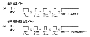
図3(a)に通常設定パターンの例を示し、スイッチ13によって商用交流電源Eを15秒オン(1回目)、オフ、5秒オン(2回目)、オフ、10秒オン(3回目)、オフ、5秒オン(4回目)、オフする。また、図3(b)に初期照度補正設定パターンの例を示し、スイッチ13によって商用交流電源Eを15秒オン(1回目)、オフ、10秒オン(2回目)、オフ、5秒オン(3回目)、オフ、10秒オン(4回目)、オフする。なお、オン時間は、点灯ユニット12に用いられる部品の動作ばらつきを考慮して±2秒の余裕を持った範囲とする。なお、制御回路18は、オン時間をタイマ21で計時して記憶部22に随時記憶させる。
FIG. 3 (a) shows an example of a normal setting pattern. The commercial AC power source E is turned on for 15 seconds (first time), off, 5 seconds on (second time), off, 10 seconds on (third time) by the
図4には、各モード毎に電源オンの回数毎に、時間、および状況をまとめた表を示す。1回目の15秒オンでモード切換操作をセットし、2回目のオンときに5秒オンであれば通常設定パターンへの切り換えであると判定するとともに10秒オンであれば初期照度補正設定パターンへの切り換えであると判定する。3回目以降は判定された各モードのさらなる確認用である。 FIG. 4 shows a table summarizing the time and situation for each number of power-on times for each mode. The mode switching operation is set with the first 15 seconds on, and if it is on for 5 seconds when it is turned on for the second time, it is determined that the mode is switched to the normal setting pattern. It is determined that the change is made. The third and subsequent times are for further confirmation of each determined mode.
制御回路18は、各パターンでの電源オンオフの途中で設定時間を満たさない電源オンの時間が入った場合、各パターンでの電源オンオフ操作を例えば1分などの所定時間以内に完了しない場合、パターン判定を初期化し、各パターンの最初からの電源オンオフ操作をしないと、パターン判定を受け付けないように構成されている。これにより、意図しないスイッチ13の操作でモードを変更してしまうのを防止できる。
If the power-on time that does not satisfy the set time is entered during power-on / off in each pattern, the
なお、各設定パターンの区別は、これらの例に限定されるものではなく、他の設定パターンで区別してもよい。例えば、照明装置10がバッテリを備える場合には、オフの時間をカウントすることが可能となるので、オフの時間を含めて設定パターンを区別してもよい。
Note that the distinction between the setting patterns is not limited to these examples, and other setting patterns may be used. For example, when the
また、制御回路18は、初期照度補正設定パターンが設定されたときに、点灯回路17を初期照度補正設定報知パターンで制御して光源11の出力を変化させ、また、通常設定パターンが設定されたときに、点灯回路17を初期照度補正設定報知パターンとは異なる通常設定報知パターンで制御して光源11の出力を変化させ、設定されたモードを容易に確認できるように報知する報知機能を有している。
Further, when the initial illuminance correction setting pattern is set, the
図5(a)に通常設定報知パターンの例を示し、光源11を所定の間隔で点滅させ、また、図5(b)に初期照度補正設定報知パターンの例を示し、光源11を徐々に明るくするようにフェードイン点灯させる。なお、各報知パターンの区別は、これらの例に限定されるものでなく、例えば点滅の間隔が大きいものと小さいもの、明るさが明るいものと暗いものなど、他の報知パターンで区別してもよい。 FIG. 5 (a) shows an example of a normal setting notification pattern, and the light source 11 blinks at a predetermined interval. FIG. 5 (b) shows an example of an initial illuminance correction setting notification pattern, and the light source 11 is gradually brightened. Turn on the fade-in. The distinction between the notification patterns is not limited to these examples, and may be distinguished by other notification patterns, for example, those having a large and small blinking interval, those having a bright brightness and those having a darkness, and the like. .
次に、初期照度補正モードおよび通常モードの設定方法を図2を参照して説明する。 Next, a method for setting the initial illuminance correction mode and the normal mode will be described with reference to FIG.
例えば、初期照度補正モードに設定される状態で、通常モードに切り換える場合、設定者がスイッチ13を通常設定パターンに合わせてオンオフ操作する(図3(a)参照)。
For example, when switching to the normal mode while being set to the initial illuminance correction mode, the setter performs an on / off operation of the
照明装置10の制御回路18では、負荷検出回路20から負荷検出信号が入力されていることを条件とし、電源オン時に電源監視回路19から入力される電源オン信号の時間を記憶部22に記憶するとともに記憶部22の記憶内容からパターンを判別する。通常設定パターンであることを判定すると、通常モードに設定し、点灯回路17を通常設定報知パターンで制御して光源11を点滅させる(図5(a)参照)。これにより、操作者に対して、通常モードに設定したことを報知する。報知後は、設定された通常モードで点灯回路17を制御する。
The
通常モードに設定された制御回路18では、調光器23からの調光信号に入力に応じて5〜100%の範囲で点灯回路17を連続調光制御する(図6および図7の破線を参照)。
In the
また、通常モードに設定される状態で、初期照度補正モードに切り換える場合、設定者がスイッチ13を初期照度補正設定パターンに合わせてオンオフ操作する(図3(b)参照)。
When switching to the initial illuminance correction mode in the state set to the normal mode, the setter performs an on / off operation of the
照明装置10の制御回路18では、負荷検出回路20から負荷検出信号が入力されていることを条件とし、電源オン時に電源監視回路19から入力される電源オン信号の時間を記憶部22に記憶するとともに記憶部22の記憶内容からパターンを判別する。初期照度補正設定パターンであることを判定すると、初期照度補正モードに設定し、点灯回路17を初期照度補正設定報知パターンで制御して光源11をフェードイン点灯させる(図5(b)参照)。これにより、操作者に対して、初期照度補正設定モードに設定したことを報知する。報知後は、設定された初期照度補正モードで点灯回路17を制御する。
The
初期照度補正モードに設定された制御回路18は、光源11の累積点灯時間に応じて初期照度補正を実施する(図6の実線を参照)。なお、制御回路18は、初期照度補正の範囲内で、調光器23からの調光信号の入力に応じて連続調光してもよい。
The
また、スイッチ13に複数の照明装置10が接続されていて、スイッチ13の操作にて複数の照明装置10が一緒に点灯、消灯する場合、複数の照明装置10のモードが一緒に設定される。このとき、各設定パターンの電源オン時間の判定は多少の余裕を持った範囲に設定しているため、各照明装置10に用いられている部品の動作ばらつきがあっても、複数の照明装置10のモードを一緒に設定できる。
When a plurality of
仮に、複数の照明装置10のうち、モードを切り換えられなかった照明装置10があった場合には、通常設定パターンと初期照度補正設定パターンとが異なっているので、再度あるいは何度か対応する設定パターンで電源オンオフ操作をすることにより、全ての照明装置10のモードを確実に切り換えることができる。
If there is a
例えば、初期照度補正モードと通常モードとを切り換える場合、1つの設定パターンで電源オンオフ操作することにより、初期照度補正モードと通常モードとを順に切り換えるようにすることは可能である。しかしながら、スイッチ13に複数の照明装置10が接続されていて、スイッチ13の操作にて複数の照明装置10が一緒に点灯、消灯する場合に、モードを切り換えられなかった照明装置10が発生すると、1つの設定パターンで電源オンオフ操作を何度もしても全ての照明装置10を同じモードに設定するのは困難である。したがって、本実施形態のように、初期照度補正モードを設定するか通常モードを設定するかに応じて、初期照度補正設定パターンまたは通常設定パターンを選択して電源オンオフ操作をすることにより、初期照度補正モードまたは通常モードを指定して設定することができ、全ての照明装置10のモードを確実に切り換えることができる。
For example, when switching between the initial illuminance correction mode and the normal mode, it is possible to sequentially switch between the initial illuminance correction mode and the normal mode by performing a power on / off operation with one setting pattern. However, when a plurality of
また、スイッチ13に複数の照明装置10が接続されていて、スイッチ13の操作にて複数の照明装置10が一緒に点灯、消灯する場合で、かつ光源11が照明装置10に対して着脱可能な場合には、モードを切り換える照明装置10の光源11は装着状態のままとし、モードを切り換えない照明装置10の光源11を外して無負荷とし、各設定パターンで電源オンオフ操作をすることにより、光源11が未装着の照明装置10のモードは切り換えないようにできる。したがって、複数の照明装置10のうち、任意の照明装置10を選択して任意のモードに設定できる。
In addition, when a plurality of
以上のように、本実施形態の照明装置10によれば、照明装置10の電源をオンオフすることにより初期照度補正モードまたは通常モードを簡単に設定することができるとともに、初期照度補正モードを設定するか通常モードを設定するかに応じて、初期照度補正設定パターンまたは通常設定パターンを選択して照明装置10の電源をオンオフすることにより、初期照度補正モードまたは通常モードを指定して設定することができる。
As described above, according to the
また、照明装置10は、初期照度補正モードが設定された場合には初期照度補正設定報知パターンで光源11の出力を変化させ、通常モードが設定された場合には初期照度補正設定報知パターンとは異なる通常設定報知パターンで光源11の出力を変化させることにより、モードの切り換えを報知できるとともに、どのモードに設定したかを報知できる。
Further, the
また、照明装置10は、連続調光機能を有しており、この連続調光機能を有しながら、初期照度補正モードと通常モードとの切り換えを容易にすることができる。
Further, the
なお、光源11が照明装置10に対して着脱可能な場合、光源11を照明装置10から外した無荷状態にあることを条件に、初期照度補正設定パターンまたは通常設定パターンで照明装置10の電源をオンオフすることにより、初期照度補正モードまたは通常モードに設定するようにしてもよい。照明装置10は、保護回路を具備することにより、無負荷で電源オンしても問題はない。
Incidentally, when the light source 11 is detachable from the
この例においても、スイッチ13に複数の照明装置10が接続されていて、スイッチ13の操作にて複数の照明装置10が一緒に点灯、消灯する場合、モードを切り換える照明装置10の光源11を外し、モードを切り換えない照明装置10の光源11を装着状態のままで、照明装置10の電源をオンオフすることにより、光源11が装着状態の照明装置10のモードは切り換えないようにできる。
Also in this example, when a plurality of
本発明のいくつかの実施形態を説明したが、これらの実施形態は、例として提示したものであり、発明の範囲を限定することは意図していない。これら新規な実施形態は、その他の様々な形態で実施されることが可能であり、発明の要旨を逸脱しない範囲で、種々の省略、置き換え、変更を行うことができる。これら実施形態やその変形は、発明の範囲や要旨に含まれるとともに、特許請求の範囲に記載された発明とその均等の範囲に含まれる。 Although several embodiments of the present invention have been described, these embodiments are presented by way of example and are not intended to limit the scope of the invention. These novel embodiments can be implemented in various other forms, and various omissions, replacements, and changes can be made without departing from the scope of the invention. These embodiments and modifications thereof are included in the scope and gist of the invention, and are included in the invention described in the claims and the equivalents thereof.
10 照明装置
11 光源
17 点灯回路
18 制御回路
20 負荷検出回路
22 累積点灯時間記憶部としての記憶部
10 Lighting equipment
11 Light source
17 Lighting circuit
18 Control circuit
20 Load detection circuit
22 Storage unit as cumulative lighting time storage unit
Claims (4)
前記光源の累積点灯時間を記憶する累積点灯時間記憶部と;
外部からの電源がオンされる時間に基づくパターンが所定の初期照度補正設定パターンであると前記光源の累積点灯時間に応じた初期照度補正をする初期照度補正モードに設定し、外部からの電源がオンされる時間に基づくパターンが所定の通常設定パターンであると初期照度補正をしない通常モードに設定し、設定されたモードで前記点灯回路を制御する制御回路と;
を具備していることを特徴とする照明装置。 A lighting circuit that turns on the light source with an external power supply;
The accumulated lighting time storage unit for storing the cumulative lighting time of the light source;
Set the initial illuminance correction mode power from the external power supply to the initial illuminance correction in accordance with the accumulated lighting time of the light source and a pattern based on the time that is on-a predetermined initial illuminance correction setting pattern, the power from the outside time-based pattern Gao down is set to the normal mode without the initial illuminance correction If it is predetermined normal setting pattern, and a control circuit for controlling the lighting circuit in the set mode;
An illumination device comprising:
前記点灯回路への前記光源の接続を検出する負荷検出回路と;A load detection circuit for detecting connection of the light source to the lighting circuit;
前記光源の累積点灯時間を記憶する累積点灯時間記憶部と;A cumulative lighting time storage unit for storing the cumulative lighting time of the light source;
前記負荷検出回路が前記光源の接続を検出するとともに外部からの電源がオンオフされるパターンが所定の初期照度補正設定パターンであると前記光源の累積点灯時間に応じた初期照度補正をする初期照度補正モードに設定し、前記負荷検出回路が前記光源の接続を検出するとともに外部からの電源がオンオフされるパターンが所定の通常設定パターンであると初期照度補正をしない通常モードに設定し、設定されたモードで前記点灯回路を制御する制御回路と;An initial illuminance correction for performing an initial illuminance correction according to the accumulated lighting time of the light source when the load detection circuit detects the connection of the light source and the pattern in which the external power supply is turned on / off is a predetermined initial illuminance correction setting pattern The mode is set, the load detection circuit detects the connection of the light source, and the pattern in which the external power supply is turned on / off is a predetermined normal setting pattern. A control circuit for controlling the lighting circuit in a mode;
を具備していることを特徴とする照明装置。An illumination device comprising:
ことを特徴とする請求項1または2記載の照明装置。 Wherein the control circuit, the initial illuminance correction setting the lighting circuit and a pattern by controlling the initial illuminance correction setting notification pattern by changing the output of the light source, the normal initial illuminance correction of the lighting circuit to be set pattern setting the illumination apparatus according to claim 1 or 2, wherein varying the output of the light source is controlled by different normal setting notification pattern from the notification pattern.
ことを特徴とする請求項1ないし3いずれか一記載の照明装置。 Wherein the control circuit, either claims 1 and controls continuous dimming the lighting circuit in accordance with at least the dimming signal inputted to the normal mode of the initial illuminance correction mode and the normal mode 3 A lighting device according to any one of the above.
Priority Applications (4)
| Application Number | Priority Date | Filing Date | Title |
|---|---|---|---|
| JP2011147048A JP5776891B2 (en) | 2011-07-01 | 2011-07-01 | Lighting device |
| US13/410,076 US8816608B2 (en) | 2011-07-01 | 2012-03-01 | Power supply device, luminaire and power source system |
| EP12157845A EP2542027A1 (en) | 2011-07-01 | 2012-03-02 | Luminaire with selectable compensation of light source aging |
| CN201210078684.8A CN102858052B (en) | 2011-07-01 | 2012-03-22 | Luminaire |
Applications Claiming Priority (1)
| Application Number | Priority Date | Filing Date | Title |
|---|---|---|---|
| JP2011147048A JP5776891B2 (en) | 2011-07-01 | 2011-07-01 | Lighting device |
Publications (2)
| Publication Number | Publication Date |
|---|---|
| JP2013016289A JP2013016289A (en) | 2013-01-24 |
| JP5776891B2 true JP5776891B2 (en) | 2015-09-09 |
Family
ID=45819012
Family Applications (1)
| Application Number | Title | Priority Date | Filing Date |
|---|---|---|---|
| JP2011147048A Active JP5776891B2 (en) | 2011-07-01 | 2011-07-01 | Lighting device |
Country Status (4)
| Country | Link |
|---|---|
| US (1) | US8816608B2 (en) |
| EP (1) | EP2542027A1 (en) |
| JP (1) | JP5776891B2 (en) |
| CN (1) | CN102858052B (en) |
Families Citing this family (2)
| Publication number | Priority date | Publication date | Assignee | Title |
|---|---|---|---|---|
| JP2019087521A (en) * | 2017-11-02 | 2019-06-06 | 洋二 前田 | Led lighting device having light control function |
| JP7065290B2 (en) * | 2018-09-26 | 2022-05-12 | パナソニックIpマネジメント株式会社 | Lighting equipment, lighting fixtures, and lighting systems |
Family Cites Families (18)
| Publication number | Priority date | Publication date | Assignee | Title |
|---|---|---|---|---|
| JPH0778693A (en) * | 1993-08-30 | 1995-03-20 | Nippon Ceramic Co Ltd | Automated illumination device |
| JP3873577B2 (en) * | 2000-05-26 | 2007-01-24 | 松下電工株式会社 | Discharge lamp lighting device and lighting apparatus using the same |
| JP2004311370A (en) * | 2003-04-02 | 2004-11-04 | Hitachi Lighting Ltd | Lighting control system |
| JP2006019244A (en) * | 2004-06-01 | 2006-01-19 | Toshiba Lighting & Technology Corp | Fluorescent lamp lighting device |
| TWI245435B (en) | 2004-10-28 | 2005-12-11 | Premier Image Technology Corp | LED control apparatus and method |
| CN1942035B (en) | 2005-09-30 | 2010-06-23 | 东芝照明技术株式会社 | Fluorescent lamp lighting device and lighting control system |
| KR101548324B1 (en) * | 2007-08-08 | 2015-09-07 | 한국전자통신연구원 | Method and apparatus for forming signals in wireless communication systems |
| JP4470985B2 (en) * | 2007-09-28 | 2010-06-02 | セイコーエプソン株式会社 | Light source device and projector |
| JP5108494B2 (en) | 2007-12-21 | 2012-12-26 | パナソニック株式会社 | Lighting device |
| US8648544B2 (en) | 2008-06-20 | 2014-02-11 | Panasonic Corporation | Illumination lighting apparatus, illumination apparatus, and illumination system |
| FI122051B (en) | 2008-06-27 | 2011-07-29 | Valopaa Oy | Lighting fixture and control procedure |
| JP4853549B2 (en) * | 2008-12-05 | 2012-01-11 | セイコーエプソン株式会社 | Discharge lamp driving method and driving device, light source device, and image display device |
| JP5379605B2 (en) * | 2009-08-25 | 2013-12-25 | パナソニック株式会社 | lighting equipment |
| CN101707836B (en) * | 2009-11-12 | 2013-05-01 | 英飞特电子(杭州)股份有限公司 | Circuit for dimming through power switch |
| JP5610803B2 (en) | 2010-03-17 | 2014-10-22 | 三菱電機照明株式会社 | Lighting device and lighting apparatus |
| JP5059175B2 (en) * | 2010-08-18 | 2012-10-24 | シャープ株式会社 | Lighting device |
| CN201869409U (en) * | 2010-10-28 | 2011-06-15 | 捷能光电科技有限公司 | Automatic dimming device of LED lighting device |
| JP5720882B2 (en) * | 2011-01-31 | 2015-05-20 | 東芝ライテック株式会社 | Lighting device and lighting device |
-
2011
- 2011-07-01 JP JP2011147048A patent/JP5776891B2/en active Active
-
2012
- 2012-03-01 US US13/410,076 patent/US8816608B2/en not_active Expired - Fee Related
- 2012-03-02 EP EP12157845A patent/EP2542027A1/en not_active Withdrawn
- 2012-03-22 CN CN201210078684.8A patent/CN102858052B/en not_active Expired - Fee Related
Also Published As
| Publication number | Publication date |
|---|---|
| JP2013016289A (en) | 2013-01-24 |
| EP2542027A1 (en) | 2013-01-02 |
| CN102858052A (en) | 2013-01-02 |
| CN102858052B (en) | 2015-05-27 |
| US20130002169A1 (en) | 2013-01-03 |
| US8816608B2 (en) | 2014-08-26 |
Similar Documents
| Publication | Publication Date | Title |
|---|---|---|
| JP5828103B2 (en) | LED lighting device and lighting apparatus using the same | |
| JP5828104B2 (en) | LED lighting device and lighting apparatus using the same | |
| JP2012133942A (en) | Led lighting device, and illumination apparatus using the same | |
| JP2009152153A (en) | Illumination device | |
| JP5776891B2 (en) | Lighting device | |
| JP2010251115A (en) | Lighting system | |
| JP5122882B2 (en) | Lighting device | |
| JP3800030B2 (en) | Lighting control device | |
| JP2010073576A (en) | Illuminating system and illuminating equipment | |
| JP2008204916A (en) | Illumination control devices and illumination device | |
| JP4802554B2 (en) | Discharge lamp lighting device and lighting fixture | |
| JP5645250B2 (en) | LED lighting device and lighting apparatus using the same | |
| JP4687208B2 (en) | Lighting device and lighting fixture | |
| JP5124095B2 (en) | Fluorescent lamp lighting device | |
| JP2006288945A (en) | Voltage control circuit of endoscope device | |
| JP4837332B2 (en) | Discharge lamp lighting device and lighting system | |
| JP2009187919A (en) | Service-lifetime display for lighting device with automatic illuminance adjusting function | |
| JP4611907B2 (en) | Discharge lamp lighting device and cumulative lighting time reset program | |
| JP2010177177A (en) | Lighting system | |
| JP7528532B2 (en) | Lighting devices, lighting equipment | |
| JP2010073575A (en) | Lighting device, illuminating equipment using the same, and illuminating system | |
| JP5314391B2 (en) | Lighting device | |
| JP2005222919A (en) | Illumination control system | |
| JP2006155948A (en) | Lighting system | |
| JP4314047B2 (en) | Lighting device |
Legal Events
| Date | Code | Title | Description |
|---|---|---|---|
| A621 | Written request for application examination |
Free format text: JAPANESE INTERMEDIATE CODE: A621 Effective date: 20140604 |
|
| A977 | Report on retrieval |
Free format text: JAPANESE INTERMEDIATE CODE: A971007 Effective date: 20150223 |
|
| A131 | Notification of reasons for refusal |
Free format text: JAPANESE INTERMEDIATE CODE: A131 Effective date: 20150225 |
|
| A521 | Request for written amendment filed |
Free format text: JAPANESE INTERMEDIATE CODE: A523 Effective date: 20150330 |
|
| TRDD | Decision of grant or rejection written | ||
| A01 | Written decision to grant a patent or to grant a registration (utility model) |
Free format text: JAPANESE INTERMEDIATE CODE: A01 Effective date: 20150610 |
|
| A61 | First payment of annual fees (during grant procedure) |
Free format text: JAPANESE INTERMEDIATE CODE: A61 Effective date: 20150623 |
|
| R151 | Written notification of patent or utility model registration |
Ref document number: 5776891 Country of ref document: JP Free format text: JAPANESE INTERMEDIATE CODE: R151 |