JP3800030B2 - Lighting control device - Google Patents
Lighting control device Download PDFInfo
- Publication number
- JP3800030B2 JP3800030B2 JP2001137778A JP2001137778A JP3800030B2 JP 3800030 B2 JP3800030 B2 JP 3800030B2 JP 2001137778 A JP2001137778 A JP 2001137778A JP 2001137778 A JP2001137778 A JP 2001137778A JP 3800030 B2 JP3800030 B2 JP 3800030B2
- Authority
- JP
- Japan
- Prior art keywords
- lighting
- unit
- time
- control device
- signal
- Prior art date
- Legal status (The legal status is an assumption and is not a legal conclusion. Google has not performed a legal analysis and makes no representation as to the accuracy of the status listed.)
- Expired - Lifetime
Links
Images


Classifications
-
- Y—GENERAL TAGGING OF NEW TECHNOLOGICAL DEVELOPMENTS; GENERAL TAGGING OF CROSS-SECTIONAL TECHNOLOGIES SPANNING OVER SEVERAL SECTIONS OF THE IPC; TECHNICAL SUBJECTS COVERED BY FORMER USPC CROSS-REFERENCE ART COLLECTIONS [XRACs] AND DIGESTS
- Y02—TECHNOLOGIES OR APPLICATIONS FOR MITIGATION OR ADAPTATION AGAINST CLIMATE CHANGE
- Y02B—CLIMATE CHANGE MITIGATION TECHNOLOGIES RELATED TO BUILDINGS, e.g. HOUSING, HOUSE APPLIANCES OR RELATED END-USER APPLICATIONS
- Y02B20/00—Energy efficient lighting technologies, e.g. halogen lamps or gas discharge lamps
- Y02B20/40—Control techniques providing energy savings, e.g. smart controller or presence detection
Landscapes
- Circuit Arrangement For Electric Light Sources In General (AREA)
Abstract
Description
【0001】
【発明の属する技術分野】
本発明は、複数の系統の照明器具の点灯状態を系統毎に制御する照明制御装置に関するものである。
【0002】
【従来の技術】
近年、事務所や工場などで各エリア毎に照明器具の適正照度やレイアウトに応じた照明範囲を自動的に設定したり、明るさセンサの検出した外光照度に応じて照明器具の照度を制御したり、予め設定されたタイムスケジュールに従って各照明器具の調光レベルを制御するなどして、省エネルギーを実現した照明制御装置の導入が増加している。
【0003】
また従来の照明制御装置では、経年変化によるランプ照度の低下を抑制するとともに、点灯初期時における無駄な電力消費を抑制するために初期照度補正や、予め設定された1日のスケジュールに従って照明器具の点灯状態を自動的に切り替えるスケジュール制御を行うものがある。
【0004】
ここで、照明制御装置による初期照度補正について説明する。一般的に点灯時間の経過とともに蛍光ランプの発光量の低下や照明器具の汚れに伴う器具効率の低下などによって照明器具の照度が低下していくため、初期照度補正を行わない場合は蛍光ランプの平均寿命を考慮して寿命末期においても設計照度が維持できるように、初期点灯時には設計照度に対してかなり明るい照度に設定されている。そのため、初期点灯時には蛍光ランプの照度が設計照度に比べてかなり明るく、余分な明るさが発生するため、無駄なエネルギーが消費されていた。それに対して、照明制御装置により初期照度補正を行う場合は、蛍光ランプの点灯時間に応じて照明器具の消費電力を制御することにより、蛍光ランプの明るさを常に設計照度に保っており、初期照度補正を行わない場合のように初期点灯時に余分な明るさが発生しないので、省エネルギーが実現される。ここで、点灯時間とは、ランプの初期使用時から現在までの間にこのランプを点灯させた時間の総和を言う。
【0005】
次に照明制御装置によるタイムスケジュール制御について説明する。タイムスケジュール制御とは、予め設定された1日のスケジュールに従って照明器具の点灯状態を自動的に切り替えるという制御である。例えば店舗内に設置された複数の照明器具を制御する場合には、準備時間中は一部の照明器具のみを間引き点灯したり、各照明器具の照度を適正照度よりも低めに設定するなどして省エネルギーを図っている。また、開店時間中は各照明器具の照度を適正照度とし、さらにバーゲンタイムなど客の多い時間帯には各照明器具の照度を適正照度よりも高くしており、時間帯毎に適切な照明環境が得られ、且つ、無駄な照明を省いて省エネルギーを図っている。
【0006】
【発明が解決しようとする課題】
ところで、事務所などに設置された複数の照明器具を制御する場合、一般的に事務所などでは同じ種類の照明器具が設置されており、複数の照明器具が同時に制御されていた。そのため、照明制御装置では各照明器具の点灯時間を一括して計時していた。
【0007】
それに対して、照明エリアを複数のゾーンに分け、各ゾーン毎に異なる照明を行う店舗では、各ゾーン(系統)毎に異なる制御を自動的に行いたいという要望があるが、各ゾーンで照明器具の点灯時間にばらつきが発生したり、点灯させる時間帯が異なるため、初期照度補正やタイムスケジュール制御などを行う場合には従来の照明制御装置では対応することができなかった。
【0008】
本発明は上記問題点に鑑みて為されたものであり、その目的とするところは、複数のゾーン毎に異なる制御を自動的に行えるようにした照明制御装置を提供するにある。
【0009】
【課題を解決するための手段】
上記目的を達成するために、請求項1の発明では、複数の系統の信号線が接続され、各系統の信号線にそれぞれ接続された調光可能な照明器具に対して系統毎に調光信号を出力する調光信号出力部と、各系統毎に調光信号を発生する制御部と、各系統の信号線にそれぞれ接続された照明器具の点灯時間を系統毎に計時するタイマ部とを備え、制御部は、タイマ部の計時した各系統毎の点灯時間に基づいて、経年変化による照度の低下を抑制するように各系統の調光信号を決定することを特徴とし、制御部は調光信号出力部を用いて各系統毎に調光信号を出力しており、タイマ部は各系統に接続された照明器具の点灯時間を系統毎に計時しているので、各系統で照明器具の点灯時間が異なる場合でも、各系統の照明器具の点灯時間を正確に計時することができ、したがって各系統の照明器具について異なる制御を行う場合にも点灯時間が系統毎に計時されているので、容易に対応することができる。そのうえ、経年変化による照度の低下を抑制することができ、且つ、タイマ部は各系統毎に点灯時間を計時しているので、各系統で照明器具の点灯時間が異なる場合でも各系統毎に経年変化による照度の低下を正確に補正することができる。
【0010】
請求項2の発明では、請求項1の発明において、系統毎に異なる種類の照明器具が接続されており、各系統に接続された照明器具に関わる情報を設定する設定部を備え、当該設定部で設定された情報に基づいて制御部が調光信号の内容を決定することを特徴とし、請求項1の発明の作用に加え、設定部を用いて各系統に接続された照明器具に関わる情報を設定することができるので、系統毎に異なる種類の照明器具が接続される場合にも、各系統に接続される照明器具の種類に応じた調光制御を行うことができる。
【0011】
請求項3の発明では、請求項1の発明において、上記制御部は、通電中に少なくとも何れか1つの系統の照明器具を点灯させており、上記タイマ部は、上記各部に電源供給する電源部の通電時間を、通電中に点灯する系統の照明器具の点灯時間として計時することを特徴とし、請求項1の発明と同様の作用を奏する。
【0012】
請求項4の発明では、請求項1の発明において、外部に接点信号を出力する外部接点出力部と、外部接点出力部から出力される接点信号に連動して少なくとも何れか1つの系統の照明器具をオン/オフさせる連動制御部とを備え、上記タイマ部は、接点信号の出力時間を、接点信号に連動して点灯する系統の照明器具の点灯時間として計時することを特徴とし、請求項1の発明と同様の作用を奏する。
【0013】
請求項5の発明では、請求項1の発明において、外部信号が入力される外部信号入力部を備え、上記制御部は外部信号入力部に入力された外部信号に連動して少なくとも何れか1つの系統の照明器具をオン/オフさせており、上記タイマ部は、外部信号の入力時間を、外部信号に連動して点灯する系統の照明器具の点灯時間として計時することを特徴とし、請求項1の発明と同様の作用を奏する。
【0014】
請求項6の発明では、請求項1の発明において、照明器具の照明範囲内に設定された検知エリアにおける人の存否を検出する人体検出部を備え、上記制御部は人体検出部の人体検知信号に連動して少なくとも何れか1つの系統の照明器具をオン/オフさせており、上記タイマ部は、制御部が人体検知信号に応じて対応する系統の照明器具を点灯させている間、この系統の照明器具の点灯時間を計時することを特徴とし、請求項1の発明の作用に加えて、人がいない時には照明器具を消灯させることによって省電力を図ることができる。
【0015】
請求項7の発明では、請求項1の発明において、所定の検知エリアの明るさを検出する明るさ検出部を備え、上記制御部は明るさ検出部の明るさ検出信号に連動して少なくとも何れか1つの系統の照明器具をオン/オフさせており、上記タイマ部は、制御部が明るさ検出信号に応じて対応する系統の照明器具を点灯させている間、この系統の照明器具の点灯時間を計時することを特徴とし、請求項1の発明の作用に加えて、周りが十分明るい時には照明器具を消灯させることによって省電力を図ることができる。
【0016】
請求項8の発明では、請求項3乃至7の発明において、上記タイマ部は、各系統の照明器具の点灯時間に対応した計時対象を計時することにより点灯時間を求めており、予め用意された複数の計時対象の中からタイマ部が計時する計時対象を選択的に設定する設定部を設けて成ることを特徴とし、請求項3乃至7の発明の作用に加えて、設定部により各系統の点灯時間を計時するための計時対象を容易に切り替えることができる。
【0017】
請求項9の発明では、請求項1乃至8の発明において、タイマ部の計時した点灯時間が予め設定されたランプ交換時間に達すると、ランプの交換時期を報知するランプ交換報知部を備えて成ることを特徴とし、請求項1乃至8の発明の作用に加えて、各系統毎に点灯時間が異なる場合でも各系統毎にランプの交換時期をユーザに知らしめることができる。
【0018】
請求項10の発明では、請求項1乃至9の発明において、各系統毎に接続可能な照明器具の台数の合計が、全体として接続可能な照明器具の台数よりも多い台数に設定されており、少なくとも何れか1つの系統に接続された照明器具の台数がこの系統の接続可能な台数を超えるか、又は、各系統に接続された照明器具の台数の合計が全体として接続可能な台数を超えると接続台数が設定台数を超過したことを報知する接続異常報知部を備えて成ることを特徴とし、請求項1乃至9の発明の作用に加えて、接続台数が予め設定された台数を超えたことをユーザに知らしめることができる。
【0020】
請求項11の発明では、請求項1乃至10の発明において、上記照明器具の照明負荷が高周波点灯専用形蛍光ランプからなることを特徴とし、請求項1乃至10の発明と同様の作用を奏する。
【0021】
【発明の実施の形態】
本発明の実施の形態を図面を参照して説明する。
【0022】
(実施形態1)
本実施形態の照明制御装置の概略構成図を図1に示す。この照明制御装置1は例えば中・大規模店舗に設置され、店舗内の照明器具2を制御するために用いられるものであり、制御部11と、調光信号出力部12と、記憶部13と、設定部14と、表示部15と、タイマ部16と、商用電源ACから電源供給されて上記各部の動作電源を生成する電源部17とで構成される。
【0023】
照明器具2は、高周波点灯専用形の蛍光ランプ21と、照明制御装置1から入力される調光制御信号に応じて蛍光ランプ21を調光点灯する点灯装置22とで構成される。
【0024】
調光信号出力部12は複数系統(本実施形態では例えば4系統)の出力ポート12a〜12dを有し、各出力ポート12a〜12dに信号線を介して接続される照明器具2に対して、制御部11から入力された調光制御信号を出力する。尚、図1では図示を簡単にするために、系統2〜4の出力ポート12b〜12dに接続されている照明器具2を省略して図示してある。
【0025】
制御部11は例えばマイクロコンピュータからなり、記憶部13、設定部14及びタイマ部16にそれぞれ設定されたデータに基づいて各系統の照明器具2にそれぞれ出力する調光制御信号を発生する。
【0026】
記憶部13は、停電時のバックアップ電源を有するRAM又はEEPROMのような不揮発性メモリとその周辺回路で構成され、各系統の照明器具2に対応する初期照度の補正データや、各照明器具の蛍光ランプの交換時間などのデータを記憶する。また、停電時には各種の設定値や各照明器具の点灯時間などのデータを記憶部13に退避させて、記憶部13に記憶させておき、電源復帰時に記憶部13に記憶された設定値や点灯時間を制御部11が読み込むものとする。
【0027】
設定部14は例えば押釦スイッチやディップスイッチなどからなり、UP、DOWN、変更、設定などの操作内容毎にスイッチが設けられており、点灯時間の積算方法の選択(すなわち点灯時間に対応した複数の計時対象の中から何れかの計時対象を選択する選択操作)、系統毎の照明器具の種類(蛍光ランプの種類)の設定、タイムスケジュールの制御内容、現在時刻などの基本設定を行うことができ、その設定値は記憶部13に保存される。
【0028】
表示部15は例えば液晶ディスプレイ(LCD)とその周辺回路とで構成され、その表示内容は制御部11によって制御される。例えば設定部14を用いて各種の設定を行う際は、制御部11が表示部15に設定内容に関する質問を表示させ、この質問に設定部14を用いて答えることにより、各系統毎に照明器具の種類や制御内容について設定することができる。また、設定時以外でも日時や各系統の照明器具2の出力値や点灯時間を表示部15に常時表示させるようにしても良く、図3(c)は表示部15の表示画面15aに各系統の点灯時間を表示させた状態を示している。尚、図3(c)の表示は系統1の照明器具の点灯時間が2時間、系統3の照明器具の点灯時間が4時間、系統2,4の照明器具の点灯時間が0時間であることを示している。また、例えば系統1の照明器具の点灯時間がランプ交換時間に達した場合には、ランプ交換時期を知らせるため、「ランプコウカンケイトウ1」のようなメッセージをランプ交換報知部たる表示部15に表示させても良いし(図3(b)参照)、系統1の照明器具において接続状態に異常が発生した場合には、異常状態を知らせるために、「イジョウケイトウ1」のようなメッセージを接続異常報知部たる表示部15に表示させても良い(図3(d)参照)。
【0029】
また、表示部15としてLCD以外に光色の異なる複数の発光ダイオードを設け、蛍光ランプ21の交換時期を発光ダイオードを用いて報知するようにしても良い。例えば、何れかの系統の照明器具2の点灯時間が予め設定されたランプ交換時間の約3分の2の時間に達すると、制御部11が通常時とは異なる色の発光ダイオードを点灯させ、その後点灯時間がランプ交換時間に達すると、制御部11がまた別の色の発光ダイオードを点灯させるか、或いは、発光ダイオードを点滅させることによって、ランプ交換時期を報知するようにしても良い。また、接続異常などの照明器具2の異常時には、発光ダイオードを点滅させることによって異常状態を報知するようにしても良い。
【0030】
タイマ部16は時刻タイマ16aと点灯時間タイマ16bとで構成される。時刻タイマ16aは現在の時刻を計時するタイマ(リアルタイムクロックを用いても良い)であり、点灯時間タイマ16bは各系統の照明器具2の点灯時間(積算時間)を個別に計時するタイマである。そして、現在の時刻を計時する時刻タイマ16aでは、タイムスケジュール制御を行う際に、設定部14で設定された開始時刻又は終了時刻が来るとトリガ信号を制御部11に出力する。また、点灯時間を計時する点灯時間タイマ16bでは電源部17の通電時間から各系統毎の点灯時間を検出しており、単位時間毎(例えば1時間毎)に各系統の点灯時間の積算値を制御部11に出力する。制御部11では点灯時間タイマ16bから各系統の点灯時間が入力されると、記憶部13に記憶させた各系統の点灯時間を更新するとともに、表示部15に表示させた点灯時間の表示を更新する。なお、点灯時間の表示は1時間毎の更新でも特に問題はないが、毎日電源部17をオン/オフさせるような場合には、電源部17をオン/オフさせるタイミングによって実際の点灯時間と記憶部13に記憶された点灯時間との間に誤差が生じるので、点灯時間タイマ16bから制御部11へ点灯時間を出力する時間間隔を短くするのが好ましい。
【0031】
調光信号出力部12は、複数の系統の照明器具2に対する調光制御信号を制御部11から受け取り、対応する系統の照明器具2に出力しているが、各照明器具2に供給する電力を制御することによって調光するようにしても良い。
【0032】
ここで、調光信号出力部12から出力される調光制御信号の制御内容について以下に簡単に説明する。制御部11では、上述のように記憶部13、設定部14及びタイマ部16からの情報に基づいて調光制御信号を設定するのであるが、点灯時間の経過に伴って蛍光ランプ21の発光量が低下したり、蛍光ランプ21が汚れてランプ光束が低下するため、時間の経過とともに点灯装置22の出力を徐々に増加させており、そのため経時的な光束低下を補正して照明器具2の照度を設計照度に保つための初期照度補正出力値と点灯時間との対応関係を示した初期照度補正用のデータテーブルを、照明器具2(すなわち蛍光ランプ21)の種類毎に複数用意している。
【0033】
而して、制御部11では、点灯時間タイマ16bの計時した点灯時間と、初期照度補正用のデータテーブルとから初期照度補正出力値を決定し、設定部14からの情報に基づいて設定された照明器具2の調光比(すなわち光出力値)に初期照度補正出力値を乗じて出力データを求める。
【0034】
(出力データ)=(光出力値)×(初期照度補正出力値)
そして、この出力データと各蛍光ランプ21に対応するデータテーブルとから実際に出力する調光制御信号(例えば点灯装置22がスイッチング電源からなる場合はスイッチング素子のデューティ比)が決定され、制御部11から調光信号出力部12へ出力される。なお、点灯時間の経過とともに初期照度補正用の出力値が変化するので、制御部11では点灯時間タイマ16bから点灯時間が入力される毎(例えば1時間毎)に初期照度補正用のデータテーブルを参照し、初期照度補正出力値が変化していれば、上述と同様の方法で調光制御信号を求める。
【0035】
次に、図2に示すように各系統毎に異なる種類の照明器具2a〜2dがそれぞれ接続された場合について以下に簡単に説明する。この場合、ユーザーが設定部14を用いて各系統に接続された照明器具2a〜2dの種類(すなわち蛍光ランプ21の種類)を設定し、設定部14で設定された蛍光ランプ21の種類が系統毎に表示部15の表示画面15aに表示される(図3(a)参照)。なお、記憶部13には各種の蛍光ランプ21についてその調光レベルの最下限値やランプ交換時間などのデータが予め登録されており、設定部14を用いて蛍光ランプ21の種類を設定すると、この蛍光ランプ21の種類に応じた調光レベルの最下限値やランプ交換時間が記憶部13から読み込まれて、自動的に設定される。例えば蛍光ランプ21の種類としてランプAを選択すると、初期照度補正有りの最下限値が40%、初期照度補正無しの最下限値が25%、ランプ交換時間が12000時間にそれぞれ設定される。尚、ランプ交換時間に関しては、ユーザー側で設定できるようにしてもよい。
【0036】
ところで、本実施形態では調光信号出力部12が4系統の出力ポート12a〜12dを有しており、各系統にはそれぞれ異なる種類の照明器具2a〜2dが接続されている。例えば出力ポート12a(系統1)にランプAを備えた照明器具2a、出力ポート12b,12c(系統2,3)にランプBを備えた照明器具2b,2c、出力ポート12d(系統4)にランプCを備えた照明器具2dがそれぞれ接続されている場合、ランプの種類によってランプ交換時間が異なるため(例えばランプAのランプ交換時間は8500時間、ランプBのランプ交換時間は12000時間、ランプCのランプ交換時間は10000時間である。)、系統毎にランプ交換時間が異なっている。
【0037】
ここで、点灯時間タイマ16bは電源部17の通電時間を計時することによって各系統毎の点灯時間を検出しており、各系統の点灯時間がその系統のランプのランプ交換時間に達すると、制御部11は図3(b)に示すようにランプの交換時期を知らせるメッセージ「ランプコウカンケイトウ1(ランプ交換系統1)」を表示部15の表示画面15aに表示させる。
【0038】
本実施形態の場合にはランプA〜Cの内、ランプAのランプ交換時間が一番短いので、まず最初にランプAの交換時期を知らせるメッセージが表示される。尚、制御部11では、ユーザーが設定部14を用いて何らかのスイッチ操作を行うまでランプの交換時期を知らせるメッセージを表示部15に表示し続ける。そして、ユーザーが系統1のランプの交換時期を知らせるメッセージを見て、ランプ交換を行い、点灯時間のリセット動作を行うと、点灯時間タイマ16bは系統1の点灯時間を0にリセットして、計時動作を再開する。尚、ユーザーが点灯時間のリセット動作を行うまで、制御部11がランプの交換時期を知らせるメッセージを表示するようにしても良い。
【0039】
ランプA〜Cの内、ランプAの次にランプ交換時間が短いのはランプCであるから、次にランプの交換時期を迎える系統は系統4である。而して、点灯時間タイマ16bの計時した系統4の点灯時間がそのランプ交換時間に達すると、制御部11はランプの交換時期を知らせるメッセージを表示部15に表示させる。ここで、系統1についてランプ交換時期を報知した際に、ユーザーが点灯時間のリセット動作を忘れて、何らリセット動作を行わなかった場合、系統4についてランプの交換時期を知らせるメッセージを表示すると同時に、系統1についてもランプの交換時期を知らせるメッセージを表示することにより、系統1のリセット動作をユーザーに促すことができる。
【0040】
尚、発光ダイオードの点灯状態によってランプの交換時期を知らせるようにしても良く、例えば2色タイプの発光ダイオードを使用し、点灯時間がランプ交換時間の約3分の2の時間までは緑点灯、ランプ交換時間の約3分の2の時間からランプ交換時間までは橙点灯、ランプ交換時間を超えると赤点灯させることによって、発光ダイオードの発光色からランプの交換時期を容易に読み取ることができる(例えば上述したランプBの場合は、点灯時間が0〜8000時間であれば緑点灯、8000〜12000時間であれば橙点灯、12000時間を超えると赤点灯となる)。ここで、ランプの交換時期を知らせるための発光ダイオードは各系統毎に設けても良いし、1個の発光ダイオードで点灯時間がランプ交換時間に一番近付いている系統の表示を行うようにしても良い。
【0041】
また本実施形態では設定部14を用いて各種の設定を行っているが、設定部14を照明制御装置1と別体とし、設定部14としてワイヤレス送信器、移動体通信の通信端末、パーソナルコンピュータなどを用い、遠隔から無線或いは有線で各種の設定を行うようにしても良い。
【0042】
上述のように本実施形態の照明制御装置1では、照明器具2の種類に応じた初期照度補正データなどの設定値を照明制御装置1に持たせているので、系統毎に異なる照明器具2が接続された場合でも1台の照明制御装置1で各照明器具2の点灯状態を制御することができる。したがって、ディスプレイエリア、一般販売エリア、特設売り場などのゾーン毎に異なる種類の照明器具2が設置される店舗においても、1台の照明制御装置1で複数台の種類の異なる照明器具2を制御することができる。また、照明制御装置1では点灯時間タイマ16bが各系統毎に点灯時間を計時しているので、系統毎に求めた点灯時間を利用して自由度の高い制御を行うことができ、各照明器具2の照度を適正照度に制御できる。
【0043】
ところで、本実施形態では1台の照明制御装置1に4系統の照明器具2が接続されるのであるが、出力部の容量の関係で1台の照明制御装置1に接続可能な照明器具2の台数には制約があり、例えば1台の照明制御装置1に接続可能な照明器具2の台数(この台数を全接続可能台数と言う。)が120台、各系統に接続可能な照明器具2の台数(この台数を系統接続可能台数と言う。)が100台に設定されている場合に、系統1に100台の照明器具2が接続されると、他の系統2〜4には合計20台しか照明器具2を接続できなくなる。
【0044】
ここで、照明制御装置1に全接続可能台数を超える数の照明器具2が接続された場合、或いは、一つの系統に系統接続可能台数を超える数の照明器具2が接続された場合、調光信号出力部12から流れる電流が予め設定してある電流値よりも大きい値となるので、設定している台数以上に照明器具2が接続されていることを検知できる。そして、調光信号出力部12から流れる電流の総和が、全接続可能台数に対応した電流値を超えた場合には、制御部11が図示しない発光ダイオードを点滅させたり、表示部15に警報表示を行わせることによって、全接続可能台数を超える台数の照明器具2が接続されたことをユーザに知らしめることができる。
【0045】
また、調光信号出力部12の各出力ポート12a〜12dに流れる電流が、系統接続可能台数に対応した電流値を超えた場合には、系統毎に予め設定してある系統接続可能台数を超える台数の照明器具2が接続されたと判断し、図3(d)に示すように表示部15の表示画面15aに「イジョウケイトウ(異常系統)1」のような警報表示を行い、何れかの系統に接続された照明器具2の台数が系統接続可能台数を超えたことをユーザに知らしめることができる。そして、各系統の接続台数が系統接続可能台数以下になり、全体の接続台数が全接続可能台数以下になれば、制御部11は表示部15による警報表示を停止させる。
【0046】
照明制御装置1に接続される複数台の照明器具2が、系統毎に予め設定されたゾーンに設置される場合、ゾーンの大きさによって接続される照明器具2の台数が異なるため、各系統に接続可能な照明器具2の台数をできるだけ増やすことが望ましい。しかしながら、照明制御装置1の大きさにも制約があり、電源部17をあまり大きくすることができないので、各系統で接続可能な台数(系統接続可能台数)の和が全接続可能台数を超えることになる。したがって、全体として接続可能な台数と各系統で接続可能な台数とのバランスをとる必要があり、照明制御装置1に接続された照明器具2の台数が全接続可能台数又は系統接続可能台数を超えた場合には、制御部11が表示部15を用いて接続異常の表示を行うので、施工ミスを早期に発見できる。また、制御部11が調光信号出力部12の各出力ポート12a〜12dに流れる電流をモニタしているので、制御動作中に断線や短絡などの事故が発生した場合にも異常状態の発生を系統毎に把握でき、配線の修理を短時間で行うことができる。
【0047】
(実施形態2)
本実施形態の照明制御装置の概略構成図を図4に示す。実施形態1の照明制御装置1では、点灯時間タイマ16bが、電源部17の通電時間をカウントすることによって各系統の照明器具2の点灯時間を計時していたが、本実施形態の照明制御装置1では、制御部11によって外部接点18aのオン/オフが制御される外部接点出力部18を設け、外部接点18aの両端間に交流電源ACを介して連動制御部たる電磁接触器3のリレーコイル31を接続している。そして、この電磁接触器3のリレー接点32を介して系統1及び系統3にそれぞれ接続された照明器具2に交流電源ACを供給している。而して、この照明制御装置1では外部接点18aのオン/オフと系統1及び系統3に接続された照明器具2への電源供給とが連動しているので、外部接点18aの導通時間をカウントすることによって、系統1,3の照明器具2の点灯時間を計時することができる。尚、外部接点出力部18及び電磁接触器3以外の構成は実施形態1と同様であるので、同一の構成要素には同一の符号を付して、その説明は省略する。また、図4では図示を簡単にするため、系統2及び系統4に接続されている照明器具2は省略して図示してある。
【0048】
ところで、この照明制御装置1を店舗で使用する場合には、準備時間中に一部の系統の照明器具2を消灯させ、間引き点灯して省エネを図るというような使用方法がある。例えば図6に示すように準備時間中に系統1及び系統3に接続された照明器具2を消灯させ、系統2及び系統4に接続された照明器具2のみを点灯させるような場合には、系統2及び系統4に接続された照明器具2の点灯時間は電源部17の通電時間から求められるが、系統1及び系統3に接続された照明器具2の点灯時間は電源部17の通電時間とは異なっている。
【0049】
そこで、本実施形態では、点灯時間タイマ16bが外部接点18aの導通時間を計時することによって、系統1及び系統3の照明器具2の点灯時間を計時している。図5は設定部14を用いて各系統の点灯時間を計時するための計時対象を設定する設定画面を示しており、系統1,3にはガイブセッテン(つまり外部接点18a)を設定し、系統2,4にはデンゲン(つまり電源部17の通電時間)を設定している。点灯時間タイマ16bは設定部14で設定された計時対象を計時することによって各系統の点灯時間をカウントしており、電源部17の通電時間をカウントすることによって系統2及び系統4に接続された照明器具2の通電時間を計時するとともに、外部接点18aの導通時間をカウントすることによって系統1及び系統3に接続された照明器具2の通電時間を計時している。
【0050】
例えば外部接点18aをオフする時間(準備時間)を午前9時から午前9時50分までの間、及び、午後8時30分から午後9時までの間とした場合、この時間帯は系統1及び系統3に接続された照明器具2を消灯させているので、上記の時間帯は点灯時間タイマ16bが系統1及び系統3の点灯時間について計時動作を行わず、午前9時50分から午後8時30分までの間のみ計時動作を行う。
【0051】
尚、外部接点18aをオン/オフさせるタイミングは、予め設定された所定期間中(例えば1日、1週間、1ヶ月、1年単位)のスケジュールにしたがって自動的にオン/オフさせても良いし、手動操作でオン/オフさせるようにしても良い。また、外部接点18aのオン/オフに連動する系統の照明器具2として、日の入りとともに点灯し日の出とともに消灯する看板灯を用い、日の入りから日の出までの時間(すなわち点灯時間)を点灯時間タイマ16bでカウントするようにしても良い。
【0052】
(実施形態3)
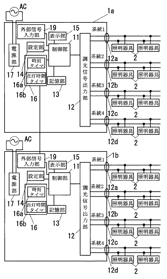
本実施形態の照明制御装置の概略構成図を図7に示す。本実施形態では、実施形態1で説明した照明制御装置において、外部から入力される外部信号を制御部11に出力する外部信号入力部19を設けており、制御部11が外部信号入力部19に入力される外部信号に連動させて少なくとも何れか1つの系統の照明器具2をオン/オフさせている。尚、外部信号入力部19以外の構成は実施形態1と同様であるので、同一の構成要素には同一の符号を付して、その説明は省略する。
【0053】
また本実施形態では照明制御装置1a,1bを2台用い、各照明制御装置1a,1bで4系統づつ、合計8系統の照明器具2を制御している。また、2台の照明制御装置1a,bの内の1台を親機、もう1台を子機とし、親機側の照明制御装置1aでは時刻タイマ16aから出力される現在の時刻情報に応じて各系統の照明器具2のスケジュール制御を行うとともに、この時刻情報を子機側の照明制御装置1bに出力している。そして、子機側の照明制御装置1bでは、外部信号入力部19が親機側の照明制御装置1aから入力された時刻情報を受け取って制御部11に出力しており、この時刻情報にしたがって制御部11が各系統の照明器具2のスケジュール制御を行っている。
【0054】
子機側の照明制御装置1bでは、少なくとも1つの系統の照明器具2のオン/オフが外部信号入力部19に入力される時刻情報と連動しているので、点灯時間タイマ16bでは外部信号入力部19に入力される時刻情報をカウントすることによって、この時刻情報で制御される系統の照明器具2の点灯時間を計時することができる。
【0055】
例えば各照明制御装置1a,1bにより店舗内の照明器具2の点灯/消灯を制御する際に、その店舗の営業時間が10:00〜20:00、準備時間が9:00〜10:00及び20:30〜21:00であり、各照明制御装置1a,1bの電源投入時間が9:00、電源切断時間が21:00となっている場合に(図1参照)、系統2,4の照明器具2を照明制御装置1a,1bに電源が投入されている間中点灯させるとともに、系統1,3の照明器具2を営業時間の間だけ点灯させる場合、親機側の照明制御装置1aから子機側の照明制御装置1bに対して、時刻情報とともに9:00〜10:00及び20:30〜21:00の間は消灯させるという制御情報が出力される。図8は設定部14を用いて各系統毎に計時対象を設定する設定画面を示しており、系統1,3の照明器具2についてはガイブニュウリョク(すなわち外部信号入力部19に入力される信号)を計時することによって点灯時間を計時し、系統2,4の照明器具2についてはデンゲン(すなわち電源部17の通電時間)を計時することによって点灯時間を計時する。而して、子機側の照明制御装置1bでは外部信号入力部19に入力された外部信号(すなわち親機側の照明制御装置1aの時刻情報及び制御情報)に基づいて、10:00〜20:30の間、系統1,3の照明器具2を点灯させるとともに、点灯時間タイマ16bが時刻情報をカウントして系統1,3の照明器具2の点灯時間を計時する。したがって、準備時間の間は点灯時間タイマ16bが系統1,3の照明器具2の点灯時間を計時することはなく、各系統の照明器具2の点灯時間を正確に計時することができる。
【0056】
【表1】
ところで、大規模な店舗などでは同じフロアに複数台の照明制御装置1が設置される場合があり、複数台の照明制御装置1でタイムスケジュール制御を別々に行うと、各照明制御装置1の時刻情報がずれているために系統間で照明器具2の動作がずれる虞があるが、本実施形態では親機側の照明制御装置1aの時刻情報を基準として、子機側の照明制御装置1bが動作しているので、複数の照明制御装置を用いてタイムスケジュール制御を行うような場合でも系統間で照明器具2の動作がずれるのを防止できる。尚、本実施形態では、複数台の照明制御装置1a,1bの内の1台を親機として、親機の時刻情報を子機に伝送しているが、基準となる時刻情報を発生する時計を別途設け、この時計の時刻情報を各照明制御装置1a,1bの外部信号入力部19に入力することで、全ての照明制御装置1a,1bの時刻情報を一致させることができる。
【0058】
また、本実施形態では子機側の照明制御装置1bの外部信号入力部19に、外部信号として親機側の照明制御装置1aの時刻情報を入力しているが、照明制御装置以外の外部機器、例えば建物全体を制御するコントローラから制御信号や警報信号を入力して、照明器具2を点灯又は消灯させるようにしても良い。なお、各照明制御装置1a,1bでは、点灯時間タイマ16bが各系統の照明器具2の点灯時間を系統毎に計時しているので、外部信号入力部19に入力される外部信号に連動した系統の点灯時間を正確に計時することができ、例えば時間経過とともに点灯出力を変化させて照明器具2の照度を一定に保つ場合にも、各照明器具2の点灯時間を正確に計時できることから、適正な照度を得ることができる。
【0059】
尚、親機側の照明制御装置1aと子機側の照明制御装置1bとの間や、各照明制御装置1a,1bと外部との間の時刻情報の伝送方式は有線でも良いし、無線でも良い。
【0060】
(実施形態4)
本実施形態の照明制御装置の概略構成図を図9に示す。本実施形態では、実施形態1で説明した照明制御装置において、照明器具2の照明範囲に設けた所定の検知エリア内の人体から放射される熱線(赤外線)を検出することによって、この検知エリアにおける人の存否を検出する赤外線センサのような人体検出部4を設けており、制御部11が人体検出部4から入力される検出信号S1に応じて少なくとも1つの系統(例えば系統1)の照明器具2をオン/オフさせている。尚、人体検出部4以外の構成は実施形態1と同様であるので、同一の構成要素には同一の符号を付して、その説明は省略する。また、図9では図示を簡単にするため、制御部11以外の構成要素や系統2〜4に接続される照明器具2などを省略して図示してある。
【0061】
ここで、制御部11が人体検出部4の人体検知信号と連動して系統1の照明器具2の点灯状態を制御する場合は、図12に示すように系統1の照明器具2の点灯時間を計時するための計時対象としてジンタイケンチ(すなわち人体検出部4の人体検知信号)を選択しており、図示しない点灯時間タイマ16bは人体検出部4から人体検出信号S1が入力されている間、系統1の照明器具2の点灯時間を計時する。
【0062】
なお、人体検出部4は人体から放射される赤外線を検出する赤外線センサを有しており、図11に示すように赤外線センサの検知レベルV1と所定の基準レベルL1との高低を比較することによって、人体の存否を示す検出信号S1を照明制御装置1に出力する。ここでは、赤外線の検知レベルV1が基準レベルL1よりも高ければ、人の存在を示す検知信号を照明制御装置1に出力し、制御部11が系統1の照明器具2を点灯させる。また、赤外線の検知レベルV1が基準レベルL1よりも低ければ、人の不在を示す検知信号を照明制御装置1に出力し、制御部11が系統1の照明器具2を消灯させる。なお、制御部11では、時刻t2又はt5において人体検出部4から人の存在を示す検出信号が入力されなくなった後も、所定の点灯保持時間T1だけ照明器具2の点灯状態を維持しており、タイマ部16では照明器具2を点灯させる間(すなわち時刻t1〜t3及び時刻t4〜t6の期間)だけ照明器具2の点灯時間を積算する。
【0063】
ところで、図10はこの照明制御装置1によって点灯状態が制御される照明器具2の配置を示しており、系統2〜4の照明器具2はそれぞれ建物6内の売り場などのゾーン7b〜7dに設置され、系統1の照明器具2は他のゾーン7b〜7dに比べて比較的点灯時間の少ないバックヤードや倉庫などのゾーン7aに設置されている。そして、人体検出部4の検知エリア4aはゾーン7aの出入口8付近に設定されているので、ゾーン7a内に人が居る場合のみゾーン7a内に設置された照明器具2を点灯させることができ、省電力を図ることができる。また、点灯時間タイマ16bでは、人体検出部4から入力される人体検出信号S1に基づいて、系統1の照明器具2の点灯時間のみ計時動作を行っているので、対応する系統1の照明器具2の点灯時間を正確に計時することができ、例えば時間経過とともに点灯出力を変化させて照明器具2の照度を一定に保つ場合にも、各照明器具2の点灯時間を正確に計時できることから、適正な照度を得ることができる。
【0064】
(実施形態5)
本実施形態の照明制御装置1の概略構成図を図13に示す。本実施形態では、実施形態1で説明した照明制御装置において、外光の照度を検出する明るさ検出部としての照度検出部5を設けており、制御部11では、照度検出部5から入力される検出信号S2に連動させて、少なくとも1つの系統(例えば系統3)の照明器具2を点灯又は消灯させている。尚、照度検出部5以外の構成は実施形態1と同様であるので、同一の構成要素には同一の符号を付して、その説明は省略する。また、図13では図示を簡単にするため、制御部11以外の構成要素や系統1,2及び4に接続される照明器具2などを省略して図示してある。
【0065】
ここで、制御部11が照度検出部5の検出信号と連動して系統3の照明器具2の点灯状態を制御する場合は、図15に示すように系統3の照明器具2の点灯時間を計時するための計時対象としてショウドケンチ(すなわち照度検出部5の検出信号S2)を選択しており、図示しない点灯時間タイマ16bでは照度検出部5から入力される検出信号S2に応じて系統3の照明器具2が点灯した時間のみを点灯時間として計時する。
【0066】
照度検出部5は、周囲の明るさに応じた電圧値の検出信号S2を発生するCdSセンサを有し、図14の時刻t11〜t12では、CdSセンサの発生した検出信号S2の検出レベルV2が所定の基準レベルL2よりも低いので(すなわち周囲の明るさが所定の基準値よりも明るいので)、制御部11は系統3の照明器具を消灯させる。一方、図14の時刻t12以降では、CdSセンサの発生した検出信号S2の検出レベルV2が所定の基準レベルL2よりも高いので(すなわち周囲の明るさが所定の基準値よりも暗いので)、制御部11は系統3の照明器具を点灯させる。そして、図示しない点灯時間タイマ16bでは制御部11が照度検出部5の検出信号S2に応じて系統3の照明器具2を点灯させる間、この系統の照明器具2の点灯時間を計時する。
【0067】
ところで、図16はこの照明制御装置1によって点灯状態が制御される照明器具2の配置を示しており、系統3の照明器具2は外光の影響を受けやすい窓際のゾーン7cに設置され、それ以外の系統1,2及び4の照明器具2は外光の影響を受け難い建物の内側のゾーン7a,7b及び7dに設置されている。そして、照度検出部5の検出エリア5aはゾーン7dの外側に設定されており、照度検出部5で外光の照度を検出し、その検出レベルが所定の基準レベルよりも明るい場合はゾーン7cに設置された照明器具2を消灯させているので、周囲が十分に明るい場合はゾーン7cの照明器具2を消灯させることによって、省電力を図ることができる。尚、本実施形態では照度検出部5によりゾーン7cの外側付近の屋外の照度を検出しているが、照度検出部5により照明器具2の周囲の照度を検出するようにしても良い。また、図17に示すように照度検出部5によって系統3の照明器具2の照度を検出するようにしても良く、この場合は照度検出部5の検出信号S2から照明器具2が点灯しているか否かを判定することができる。
【0068】
また、実施形態4で説明した人体検出部4と組み合わせ、照度検出部5の検出した明るさが基準の明るさよりも暗く、且つ、人体検出部4が人を検出した時は制御部11が対応する系統の照明器具2を点灯させ、照度検出部5の検出した明るさが基準の明るさよりも明るい場合は対応する系統の照明器具2を消灯させるようにしても良く、周囲が十分に明るい場合や周囲に人がいない場合には照明器具2を消灯させることによって、省電力を図ることができる。
【0069】
また更に、点灯時間タイマ16bでは、照度検出部5や人体検出部4から入力される検出信号S2,S1に基づいて制御部11が照明器具2を点灯させている間だけ点灯時間の計時動作を行っているので、各系統の照明器具2の点灯時間を正確に計時することができ、例えば時間経過とともに点灯出力を変化させて照明器具2の照度を一定に保つ場合にも、各照明器具2の点灯時間を正確に計時できることから、適正な照度を得ることができる。
【0070】
【発明の効果】
上述のように、請求項1の発明は、複数の系統の信号線が接続され、各系統の信号線にそれぞれ接続された調光可能な照明器具に対して系統毎に調光信号を出力する調光信号出力部と、各系統毎に調光信号を発生する制御部と、各系統の信号線にそれぞれ接続された照明器具の点灯時間を系統毎に計時するタイマ部とを備え、制御部は、タイマ部の計時した各系統毎の点灯時間に基づいて、経年変化による照度の低下を抑制するように各系統の調光信号を決定することを特徴とし、制御部は調光信号出力部を用いて各系統毎に調光信号を出力しており、タイマ部は各系統に接続された照明器具の点灯時間を系統毎に計時しているので、各系統で照明器具の点灯時間が異なる場合でも、各系統の照明器具の点灯時間を正確に計時することができ、したがって各系統の照明器具について異なる制御を行う場合にも点灯時間が系統毎に計時されているので、容易に対応できるという効果がある。そのうえ、経年変化による照度の低下を抑制することができ、且つ、タイマ部は各系統毎に点灯時間を計時しているので、各系統で照明器具の点灯時間が異なる場合でも各系統毎に経年変化による照度の低下を正確に補正することができるという効果がある。
【0071】
請求項2の発明は、請求項1の発明において、系統毎に異なる種類の照明器具が接続されており、各系統に接続された照明器具に関わる情報を設定する設定部を備え、当該設定部で設定された情報に基づいて制御部が調光信号の内容を決定することを特徴とし、請求項1の発明の効果に加え、設定部を用いて各系統に接続された照明器具に関わる情報を設定することができるので、系統毎に異なる種類の照明器具が接続される場合にも、各系統に接続される照明器具の種類に応じた調光制御を行えるという効果がある。
【0072】
請求項3の発明は、請求項1の発明において、上記制御部は、通電中に少なくとも何れか1つの系統の照明器具を点灯させており、上記タイマ部は、上記各部に電源供給する電源部の通電時間を、通電中に点灯する系統の照明器具の点灯時間として計時することを特徴とし、請求項1の発明と同様の効果を奏する。
【0073】
請求項4の発明は、請求項1の発明において、外部に接点信号を出力する外部接点出力部と、外部接点出力部から出力される接点信号に連動して少なくとも何れか1つの系統の照明器具をオン/オフさせる連動制御部とを備え、上記タイマ部は、接点信号の出力時間を、接点信号に連動して点灯する系統の照明器具の点灯時間として計時することを特徴とし、請求項1の発明と同様の効果を奏する。
【0074】
請求項5の発明は、請求項1の発明において、外部信号が入力される外部信号入力部を備え、上記制御部は外部信号入力部に入力された外部信号に連動して少なくとも何れか1つの系統の照明器具をオン/オフさせており、上記タイマ部は、外部信号の入力時間を、外部信号に連動して点灯する系統の照明器具の点灯時間として計時することを特徴とし、請求項1の発明と同様の効果を奏する。
【0075】
請求項6の発明は、請求項1の発明において、照明器具の照明範囲内に設定された検知エリアにおける人の存否を検出する人体検出部を備え、上記制御部は人体検出部の人体検知信号に連動して少なくとも何れか1つの系統の照明器具をオン/オフさせており、上記タイマ部は、制御部が人体検知信号に応じて対応する系統の照明器具を点灯させている間、この系統の照明器具の点灯時間を計時することを特徴とし、請求項1の発明の効果に加えて、人がいない時には照明器具を消灯させることによって省電力を図ることができるという効果がある。
【0076】
請求項7の発明は、請求項1の発明において、所定の検知エリアの明るさを検出する明るさ検出部を備え、上記制御部は明るさ検出部の明るさ検出信号に連動して少なくとも何れか1つの系統の照明器具をオン/オフさせており、上記タイマ部は、制御部が明るさ検出信号に応じて対応する系統の照明器具を点灯させている間、この系統の照明器具の点灯時間を計時することを特徴とし、請求項1の発明の効果に加えて、周りが十分明るい時には照明器具を消灯させることによって省電力を図ることができるという効果がある。
【0077】
請求項8の発明は、請求項3乃至7の発明において、上記タイマ部は、各系統の照明器具の点灯時間に対応した計時対象を計時することにより点灯時間を求めており、予め用意された複数の計時対象の中からタイマ部が計時する計時対象を選択的に設定する設定部を設けて成ることを特徴とし、請求項3乃至7の発明の効果に加えて、設定部により各系統の点灯時間を計時するための計時対象を容易に切り替えることができるという効果がある。
【0078】
請求項9の発明は、請求項1乃至8の発明において、タイマ部の計時した点灯時間が予め設定されたランプ交換時間に達すると、ランプの交換時期を報知するランプ交換報知部を備えて成ることを特徴とし、請求項1乃至8の発明の効果に加えて、各系統毎に点灯時間が異なる場合でも各系統毎にランプの交換時期をユーザに知らしめることができるという効果がある。
【0079】
請求項10の発明は、請求項1乃至9の発明において、各系統毎に接続可能な照明器具の台数の合計が、全体として接続可能な照明器具の台数よりも多い台数に設定されており、少なくとも何れか1つの系統に接続された照明器具の台数がこの系統の接続可能な台数を超えるか、又は、各系統に接続された照明器具の台数の合計が全体として接続可能な台数を超えると接続台数が設定台数を超過したことを報知する接続異常報知部を備えて成ることを特徴とし、請求項1乃至9の発明の効果に加えて、接続台数が予め設定された台数を超えたことをユーザに知らしめることができるという効果がある。
【0081】
請求項11の発明は、請求項1乃至10の発明において、上記照明器具の照明負荷が高周波点灯専用形蛍光ランプからなることを特徴とし、請求項1乃至10の発明と同様の効果を奏する。
【図面の簡単な説明】
【図1】実施形態1の照明制御装置の概略構成図である。
【図2】同上の照明制御装置に系統毎に異なる種類の照明器具を接続した状態を示す概略構成図である。
【図3】(a)〜(d)は同上の表示部の表示内容を説明する説明図である。
【図4】実施形態2の照明制御装置の概略構成図である。
【図5】同上の表示部の表示内容を説明する図である。
【図6】同上の制御状態を説明する説明図である。
【図7】実施形態3の照明制御装置の概略構成図である。
【図8】同上の表示部の表示内容を説明する説明図である。
【図9】実施形態4の照明制御装置の概略構成図である。
【図10】同上の照明器具の配置を説明する説明図である。
【図11】同上の人体検出部の検出信号と照明器具の点灯状態との関係を示す図である。
【図12】同上の表示部の表示内容を説明する説明図である。
【図13】実施形態5の照明制御装置の概略構成図である。
【図14】同上の照度検出部の検出信号と照明器具の点灯状態との関係を示す図である。
【図15】同上の表示部の表示内容を説明する説明図である。
【図16】同上の照明器具の配置を説明する説明図である。
【図17】同上の別の照明制御装置の概略構成図である。
【符号の説明】
1 照明制御装置
2 照明器具
11 制御部
12 調光信号出力部
16 タイマ部[0001]
BACKGROUND OF THE INVENTION
The present invention relates to an illumination control device that controls lighting states of a plurality of systems of lighting fixtures for each system.
[0002]
[Prior art]
In recent years, the appropriate illumination intensity range and lighting range according to the layout is automatically set for each area in offices and factories, and the illumination intensity of the lighting fixtures is controlled according to the ambient light intensity detected by the brightness sensor. In addition, the introduction of lighting control devices that realize energy saving by controlling the dimming level of each lighting fixture according to a preset time schedule is increasing.
[0003]
In addition, in the conventional lighting control device, the lamp illuminance is prevented from decreasing due to secular change, and the illuminator is adjusted according to the initial illuminance correction or the preset daily schedule in order to suppress unnecessary power consumption at the initial lighting stage. Some perform schedule control to automatically switch the lighting state.
[0004]
Here, the initial illuminance correction by the illumination control device will be described. Generally, the illuminance of a lighting fixture decreases due to a decrease in the amount of light emitted from the fluorescent lamp and the efficiency of the fixture due to contamination of the lighting fixture as the lighting time elapses. Considering the average life, the illuminance is set to be considerably brighter than the design illuminance at the time of initial lighting so that the design illuminance can be maintained even at the end of the life. For this reason, when the lamp is initially lit, the illuminance of the fluorescent lamp is considerably brighter than the design illuminance and extra brightness is generated, so that useless energy is consumed. On the other hand, when the initial illumination correction is performed by the lighting control device, the brightness of the fluorescent lamp is always kept at the designed illuminance by controlling the power consumption of the lighting fixture according to the lighting time of the fluorescent lamp. As in the case where illuminance correction is not performed, extra brightness does not occur at the time of initial lighting, so energy saving is realized. Here, the lighting time refers to the total time during which the lamp is lit from the initial use of the lamp to the present time.
[0005]
Next, time schedule control by the illumination control device will be described. Time schedule control is control of automatically switching the lighting state of a lighting fixture according to a preset daily schedule. For example, when controlling multiple lighting fixtures installed in a store, only some of the lighting fixtures are turned on during the preparation time, or the illuminance of each lighting fixture is set lower than the appropriate illuminance. To save energy. In addition, the illuminance of each lighting fixture is set to the appropriate illuminance during opening hours, and the illuminance of each lighting fixture is set higher than the appropriate illuminance during times when there are many customers, such as bargain hours. And saving energy by eliminating unnecessary lighting.
[0006]
[Problems to be solved by the invention]
By the way, when controlling a plurality of lighting fixtures installed in an office or the like, generally the same type of lighting fixtures are installed in an office or the like, and the plurality of lighting fixtures are controlled simultaneously. For this reason, the lighting control device collectively measures the lighting time of each lighting fixture.
[0007]
On the other hand, in a store that divides the lighting area into a plurality of zones and performs different lighting for each zone, there is a desire to automatically perform different control for each zone (system). Since the lighting time varies and the lighting time zone is different, the conventional illumination control device cannot cope with the initial illumination correction or the time schedule control.
[0008]
The present invention has been made in view of the above problems, and an object thereof is to provide an illumination control apparatus that can automatically perform different control for each of a plurality of zones.
[0009]
[Means for Solving the Problems]
In order to achieve the above object, according to the first aspect of the present invention, a plurality of signal lines are connected, and a dimming signal is provided for each system with respect to a dimmable lighting fixture connected to each signal line. A dimming signal output unit, a control unit for generating a dimming signal for each system, and a timer unit for measuring the lighting time of the luminaire connected to the signal line of each system for each system.The control unit determines the dimming signal for each system so as to suppress a decrease in illuminance due to secular change based on the lighting time of each system timed by the timer unit.The control unit outputs a dimming signal for each system using the dimming signal output unit, and the timer unit counts the lighting time of the luminaire connected to each system for each system. Therefore, even when the lighting times of the lighting fixtures are different in each system, it is possible to accurately measure the lighting times of the lighting fixtures of each system. Since each system is timed, it can be easily handled.In addition, it is possible to suppress a decrease in illuminance due to secular change, and the timer unit measures the lighting time for each system, so even if the lighting time of the luminaire is different for each system, The decrease in illuminance due to the change can be accurately corrected.
[0010]
In the invention of
[0011]
According to a third aspect of the present invention, in the first aspect of the present invention, the control unit turns on at least one of the lighting fixtures during energization, and the timer unit supplies power to each unit. The current-carrying time is counted as the lighting time of a lighting fixture of a system that is lit during power-on, and the same effect as the invention of
[0012]
According to a fourth aspect of the present invention, in the first aspect of the invention, an external contact output unit that outputs a contact signal to the outside, and at least one of the lighting fixtures linked to the contact signal output from the external contact output unit And an interlock control unit for turning on / off the timer, wherein the timer unit measures the output time of the contact signal as the lighting time of a lighting fixture of a system that lights up in conjunction with the contact signal. The same effect as that of the present invention is achieved.
[0013]
According to a fifth aspect of the invention, in the first aspect of the invention, an external signal input unit to which an external signal is input is provided, and the control unit is linked to at least one of the external signals input to the external signal input unit. The lighting device of the system is turned on / off, and the timer section measures the input time of the external signal as the lighting time of the lighting device of the system that lights up in conjunction with the external signal. The same effect as that of the present invention is achieved.
[0014]
According to a sixth aspect of the present invention, in the first aspect of the invention, a human body detection unit that detects the presence or absence of a person in a detection area set within the illumination range of the lighting fixture is provided, and the control unit is a human body detection signal of the human body detection unit. At least one of the lighting fixtures is turned on / off in conjunction with the timer, and the timer unit is turned on while the control unit turns on the corresponding lighting fixtures according to the human body detection signal. In addition to the operation of the first aspect of the present invention, when the luminaire is turned off, it is possible to save power by turning off the luminaire.
[0015]
According to a seventh aspect of the present invention, in the first aspect of the present invention, a brightness detection unit that detects the brightness of a predetermined detection area is provided, and the control unit is linked to a brightness detection signal of the brightness detection unit. The lighting unit is turned on / off, and the timer unit turns on the lighting device of this system while the control unit lights the corresponding lighting device according to the brightness detection signal. In addition to the operation of the invention of
[0016]
In the invention of
[0017]
According to a ninth aspect of the present invention, in the first to eighth aspects of the present invention, a lamp replacement notifying unit is provided for notifying a lamp replacement time when the lighting time measured by the timer unit reaches a preset lamp replacement time. In addition to the effects of the first to eighth aspects of the invention, even when the lighting time differs for each system, the user can be notified of the lamp replacement time for each system.
[0018]
In the invention of claim 10, in the inventions of
[0020]
Claim11In the present invention, claims 1 to10In the invention, the lighting load of the luminaire is a high-frequency lighting-only fluorescent lamp, characterized in that10The same effect as that of the present invention is achieved.
[0021]
DETAILED DESCRIPTION OF THE INVENTION
Embodiments of the present invention will be described with reference to the drawings.
[0022]
(Embodiment 1)
The schematic block diagram of the illumination control apparatus of this embodiment is shown in FIG. The
[0023]
The
[0024]
The dimming
[0025]
The
[0026]
The
[0027]
The setting
[0028]
The
[0029]
In addition to the LCD, a plurality of light emitting diodes having different light colors may be provided as the
[0030]
The
[0031]
The dimming
[0032]
Here, the control content of the dimming control signal output from the dimming
[0033]
Thus, the
[0034]
(Output data) = (Light output value) x (Initial illumination correction output value)
Then, a dimming control signal (for example, the duty ratio of the switching element when the
[0035]
Next, the case where different types of
[0036]
By the way, in this embodiment, the light control
[0037]
Here, the
[0038]
In the case of this embodiment, the lamp replacement time of the lamp A among the lamps A to C is the shortest, so a message notifying the replacement time of the lamp A is displayed first. Note that the
[0039]
Among the lamps A to C, the lamp C has the shortest lamp replacement time after the lamp A. Therefore, the system that reaches the next lamp replacement time is the
[0040]
The lamp replacement time may be notified by the lighting state of the light emitting diode. For example, a two-color type light emitting diode is used, and the green lighting is performed until the lighting time is about two thirds of the lamp replacement time. The lamp replacement time can be easily read from the emission color of the light emitting diode by turning on the orange light from about two-thirds of the lamp replacement time to the lamp replacement time, and turning on the red light when the lamp replacement time is exceeded ( For example, in the case of the lamp B described above, if the lighting time is 0 to 8000 hours, the green light is lit, if it is 8000 to 12000 hours, the light is orange, and if it exceeds 12000 hours, the light is red. Here, a light emitting diode for informing the lamp replacement time may be provided for each system, or a single light emitting diode may display the system whose lighting time is closest to the lamp replacement time. Also good.
[0041]
In the present embodiment, various settings are performed using the
[0042]
As described above, in the
[0043]
By the way, in this embodiment, although four systems of
[0044]
Here, when the number of
[0045]
When the current flowing through each
[0046]
When a plurality of
[0047]
(Embodiment 2)
FIG. 4 shows a schematic configuration diagram of the illumination control device of the present embodiment. In the
[0048]
By the way, when this
[0049]
Therefore, in this embodiment, the
[0050]
For example, when the time (preparation time) for turning off the
[0051]
The timing for turning on / off the
[0052]
(Embodiment 3)
FIG. 7 shows a schematic configuration diagram of the illumination control device of the present embodiment. In the present embodiment, in the lighting control apparatus described in the first embodiment, an external signal input unit 19 that outputs an external signal input from the outside to the
[0053]
In this embodiment, two
[0054]
In the
[0055]
For example, when the
[0056]
[Table 1]
By the way, in a large-scale store or the like, a plurality of
[0058]
In this embodiment, the time information of the lighting control device 1a on the parent device side is input as an external signal to the external signal input unit 19 of the
[0059]
The time information transmission method between the lighting control device 1a on the parent device side and the
[0060]
(Embodiment 4)
FIG. 9 shows a schematic configuration diagram of the illumination control device of the present embodiment. In the present embodiment, in the lighting control apparatus described in the first embodiment, by detecting heat rays (infrared rays) emitted from a human body in a predetermined detection area provided in the illumination range of the
[0061]
Here, when the
[0062]
The human
[0063]
Incidentally, FIG. 10 shows the arrangement of the
[0064]
(Embodiment 5)
The schematic block diagram of the
[0065]
Here, when the
[0066]
The
[0067]
By the way, FIG. 16 shows the arrangement of the
[0068]
Further, in combination with the human
[0069]
Still further, the
[0070]
【The invention's effect】
As described above, according to the first aspect of the present invention, a plurality of signal lines are connected, and a dimming signal is output for each system with respect to a dimmable lighting fixture connected to each signal line. A dimming signal output unit, a control unit that generates a dimming signal for each system, and a timer unit that counts the lighting time of the luminaire connected to the signal line of each system for each systemThe control unit determines the dimming signal for each system so as to suppress a decrease in illuminance due to secular change based on the lighting time of each system timed by the timer unit.The control unit outputs a dimming signal for each system using the dimming signal output unit, and the timer unit counts the lighting time of the luminaire connected to each system for each system. Therefore, even when the lighting times of the lighting fixtures are different in each system, it is possible to accurately measure the lighting times of the lighting fixtures of each system. Since each system is timed, there is an effect that it can be easily handled.In addition, it is possible to suppress a decrease in illuminance due to secular change, and the timer unit measures the lighting time for each system, so even if the lighting time of the luminaire is different for each system, There is an effect that a decrease in illuminance due to a change can be accurately corrected.
[0071]
The invention of
[0072]
According to a third aspect of the present invention, in the first aspect of the invention, the control unit turns on at least one of the lighting fixtures during energization, and the timer unit supplies power to the units. The current-carrying time is counted as the lighting time of a lighting fixture of a system that is lit during power-on, and the same effect as the invention of
[0073]
According to a fourth aspect of the present invention, in the first aspect of the invention, an external contact output unit that outputs a contact signal to the outside, and a lighting fixture of at least one of the systems linked to the contact signal output from the external contact output unit And an interlock control unit for turning on / off the timer, wherein the timer unit measures the output time of the contact signal as the lighting time of a lighting fixture of a system that lights up in conjunction with the contact signal. The same effect as that of the present invention can be obtained.
[0074]
According to a fifth aspect of the present invention, in the first aspect of the invention, an external signal input unit to which an external signal is input is provided, and the control unit is linked to at least one of the external signals input to the external signal input unit. The system lighting device is turned on / off, and the timer unit measures the input time of the external signal as the lighting time of the system lighting device that lights up in conjunction with the external signal. The same effect as that of the present invention can be obtained.
[0075]
According to a sixth aspect of the present invention, in the first aspect of the present invention, a human body detection unit that detects the presence or absence of a person in a detection area set within the illumination range of the luminaire is provided, and the control unit is a human body detection signal of the human body detection unit. At least one of the lighting fixtures is turned on / off in conjunction with the timer, and the timer unit is turned on while the control unit turns on the corresponding lighting fixtures according to the human body detection signal. In addition to the effect of the first aspect of the invention, when the luminaire is turned off, it is possible to save power by turning off the luminaire.
[0076]
According to a seventh aspect of the present invention, in the first aspect of the present invention, a brightness detection unit that detects the brightness of a predetermined detection area is provided, and the control unit is linked at least in conjunction with a brightness detection signal of the brightness detection unit. The lighting unit is turned on / off, and the timer unit turns on the lighting device of this system while the control unit lights the corresponding lighting device according to the brightness detection signal. In addition to the effect of the invention of
[0077]
The invention according to
[0078]
According to a ninth aspect of the present invention, in the first to eighth aspects of the invention, a lamp replacement notifying unit for notifying a lamp replacement time when the lighting time measured by the timer unit reaches a preset lamp replacement time is provided. In addition to the effects of the inventions of
[0079]
The invention of claim 10 is the invention of
[0081]
Claim11The invention of
[Brief description of the drawings]
FIG. 1 is a schematic configuration diagram of a lighting control apparatus according to a first embodiment.
FIG. 2 is a schematic configuration diagram showing a state in which different types of lighting fixtures are connected to each lighting system in the same lighting control device.
FIGS. 3A to 3D are explanatory diagrams for explaining display contents of the display unit. FIG.
FIG. 4 is a schematic configuration diagram of a lighting control apparatus according to a second embodiment.
FIG. 5 is a diagram for explaining display contents on the display unit.
FIG. 6 is an explanatory diagram for explaining the control state of the above.
FIG. 7 is a schematic configuration diagram of a lighting control apparatus according to a third embodiment.
FIG. 8 is an explanatory diagram for explaining display contents on the display unit.
FIG. 9 is a schematic configuration diagram of a lighting control apparatus according to a fourth embodiment.
FIG. 10 is an explanatory diagram for explaining the arrangement of the lighting fixtures.
FIG. 11 is a diagram showing the relationship between the detection signal of the human body detection unit and the lighting state of the luminaire.
FIG. 12 is an explanatory diagram for explaining display contents on the display unit of the above.
FIG. 13 is a schematic configuration diagram of a lighting control apparatus according to a fifth embodiment.
FIG. 14 is a diagram showing the relationship between the detection signal of the illuminance detection unit and the lighting state of the luminaire.
FIG. 15 is an explanatory diagram for explaining display contents on the display unit.
FIG. 16 is an explanatory diagram for explaining the arrangement of the lighting fixtures.
FIG. 17 is a schematic configuration diagram of another illumination control device according to the first embodiment.
[Explanation of symbols]
1 Lighting control device
2 lighting equipment
11 Control unit
12 Dimming signal output section
16 Timer section
Claims (11)
Priority Applications (1)
| Application Number | Priority Date | Filing Date | Title |
|---|---|---|---|
| JP2001137778A JP3800030B2 (en) | 2001-05-08 | 2001-05-08 | Lighting control device |
Applications Claiming Priority (1)
| Application Number | Priority Date | Filing Date | Title |
|---|---|---|---|
| JP2001137778A JP3800030B2 (en) | 2001-05-08 | 2001-05-08 | Lighting control device |
Publications (2)
| Publication Number | Publication Date |
|---|---|
| JP2002334794A JP2002334794A (en) | 2002-11-22 |
| JP3800030B2 true JP3800030B2 (en) | 2006-07-19 |
Family
ID=18984825
Family Applications (1)
| Application Number | Title | Priority Date | Filing Date |
|---|---|---|---|
| JP2001137778A Expired - Lifetime JP3800030B2 (en) | 2001-05-08 | 2001-05-08 | Lighting control device |
Country Status (1)
| Country | Link |
|---|---|
| JP (1) | JP3800030B2 (en) |
Cited By (1)
| Publication number | Priority date | Publication date | Assignee | Title |
|---|---|---|---|---|
| KR100927745B1 (en) * | 2009-08-31 | 2009-11-19 | (주)코맨텍 | A automatic lighting unit by steps using photosensing and lighting method thereof |
Families Citing this family (9)
| Publication number | Priority date | Publication date | Assignee | Title |
|---|---|---|---|---|
| JP2006236668A (en) * | 2005-02-23 | 2006-09-07 | Matsushita Electric Works Ltd | Lighting controller |
| JP4790385B2 (en) * | 2005-11-16 | 2011-10-12 | 岩崎電気株式会社 | Lighting control apparatus and lighting control method |
| JP2007252614A (en) * | 2006-03-23 | 2007-10-04 | Sanyo Electric Co Ltd | Showcase |
| JP4915662B2 (en) * | 2007-03-27 | 2012-04-11 | パナソニック株式会社 | Lighting system |
| JP2008237113A (en) * | 2007-03-27 | 2008-10-09 | Matsushita Electric Works Ltd | Illumination system for room to live together with pet |
| JP5385804B2 (en) * | 2010-01-26 | 2014-01-08 | パナソニック株式会社 | Environmental control system |
| JP5853204B2 (en) * | 2010-09-27 | 2016-02-09 | パナソニックIpマネジメント株式会社 | Lighting control system |
| CN103460809B (en) * | 2011-03-31 | 2015-04-22 | 柯尼卡美能达美国研究所有限公司 | Adaptive lighting system with low energy consumption |
| CN113660750A (en) * | 2021-07-09 | 2021-11-16 | 佛山电器照明股份有限公司 | Illumination regulation and control method, data processing center and illumination regulation and control system |
-
2001
- 2001-05-08 JP JP2001137778A patent/JP3800030B2/en not_active Expired - Lifetime
Cited By (1)
| Publication number | Priority date | Publication date | Assignee | Title |
|---|---|---|---|---|
| KR100927745B1 (en) * | 2009-08-31 | 2009-11-19 | (주)코맨텍 | A automatic lighting unit by steps using photosensing and lighting method thereof |
Also Published As
| Publication number | Publication date |
|---|---|
| JP2002334794A (en) | 2002-11-22 |
Similar Documents
| Publication | Publication Date | Title |
|---|---|---|
| US9560703B2 (en) | Dimming control for emergency lighting systems | |
| US7391159B2 (en) | Lighting device with multiple power sources and multiple modes of operation | |
| KR101223969B1 (en) | Led drive circuit, phase control dimmer, led illumination fixture, led illumination device, and led illumination system | |
| JP4586567B2 (en) | lighting equipment | |
| KR100904792B1 (en) | Led lamp management system | |
| WO2013001756A1 (en) | Led illumination circuit and led illumination device | |
| JP3800030B2 (en) | Lighting control device | |
| JP4760110B2 (en) | Lighting device, lighting fixture, lighting system | |
| CA2743752C (en) | Extending service life of lighting fixtures | |
| JP2010251115A (en) | Lighting system | |
| JP2010092812A (en) | Solar cell type high brightness led sensor light | |
| JP2002373794A (en) | Lighting system | |
| JP2008210887A (en) | Led control system | |
| JP2002252092A (en) | Illumination device | |
| KR20160079638A (en) | Apparatus and method for confirming dimming status of illuminator | |
| JP5776891B2 (en) | Lighting device | |
| JP6160268B2 (en) | Lighting device and lighting device | |
| JP2012074151A (en) | Lighting control system | |
| JP6380618B2 (en) | Lighting device | |
| JPH0869883A (en) | Lighting facility control system | |
| JP3903641B2 (en) | Lighting device | |
| JP2003017278A (en) | Illumination system | |
| JP2006019244A (en) | Fluorescent lamp lighting device | |
| JPH0869884A (en) | Luminaire | |
| JP2012113909A (en) | Lighting fixture |
Legal Events
| Date | Code | Title | Description |
|---|---|---|---|
| A621 | Written request for application examination |
Free format text: JAPANESE INTERMEDIATE CODE: A621 Effective date: 20040526 |
|
| A977 | Report on retrieval |
Free format text: JAPANESE INTERMEDIATE CODE: A971007 Effective date: 20051227 |
|
| A131 | Notification of reasons for refusal |
Free format text: JAPANESE INTERMEDIATE CODE: A131 Effective date: 20060110 |
|
| A521 | Written amendment |
Free format text: JAPANESE INTERMEDIATE CODE: A523 Effective date: 20060313 |
|
| TRDD | Decision of grant or rejection written | ||
| A01 | Written decision to grant a patent or to grant a registration (utility model) |
Free format text: JAPANESE INTERMEDIATE CODE: A01 Effective date: 20060404 |
|
| A61 | First payment of annual fees (during grant procedure) |
Free format text: JAPANESE INTERMEDIATE CODE: A61 Effective date: 20060417 |
|
| R151 | Written notification of patent or utility model registration |
Ref document number: 3800030 Country of ref document: JP Free format text: JAPANESE INTERMEDIATE CODE: R151 |
|
| FPAY | Renewal fee payment (event date is renewal date of database) |
Free format text: PAYMENT UNTIL: 20090512 Year of fee payment: 3 |
|
| S533 | Written request for registration of change of name |
Free format text: JAPANESE INTERMEDIATE CODE: R313533 |
|
| FPAY | Renewal fee payment (event date is renewal date of database) |
Free format text: PAYMENT UNTIL: 20090512 Year of fee payment: 3 |
|
| R350 | Written notification of registration of transfer |
Free format text: JAPANESE INTERMEDIATE CODE: R350 |
|
| FPAY | Renewal fee payment (event date is renewal date of database) |
Free format text: PAYMENT UNTIL: 20100512 Year of fee payment: 4 |
|
| FPAY | Renewal fee payment (event date is renewal date of database) |
Free format text: PAYMENT UNTIL: 20100512 Year of fee payment: 4 |
|
| FPAY | Renewal fee payment (event date is renewal date of database) |
Free format text: PAYMENT UNTIL: 20110512 Year of fee payment: 5 |
|
| FPAY | Renewal fee payment (event date is renewal date of database) |
Free format text: PAYMENT UNTIL: 20120512 Year of fee payment: 6 |
|
| FPAY | Renewal fee payment (event date is renewal date of database) |
Free format text: PAYMENT UNTIL: 20120512 Year of fee payment: 6 |
|
| FPAY | Renewal fee payment (event date is renewal date of database) |
Free format text: PAYMENT UNTIL: 20130512 Year of fee payment: 7 |
|
| FPAY | Renewal fee payment (event date is renewal date of database) |
Free format text: PAYMENT UNTIL: 20130512 Year of fee payment: 7 |
|
| EXPY | Cancellation because of completion of term |