JP5774039B2 - Memory card connector - Google Patents
Memory card connector Download PDFInfo
- Publication number
- JP5774039B2 JP5774039B2 JP2013034959A JP2013034959A JP5774039B2 JP 5774039 B2 JP5774039 B2 JP 5774039B2 JP 2013034959 A JP2013034959 A JP 2013034959A JP 2013034959 A JP2013034959 A JP 2013034959A JP 5774039 B2 JP5774039 B2 JP 5774039B2
- Authority
- JP
- Japan
- Prior art keywords
- contact
- memory card
- group
- insulator
- piece
- Prior art date
- Legal status (The legal status is an assumption and is not a legal conclusion. Google has not performed a legal analysis and makes no representation as to the accuracy of the status listed.)
- Expired - Fee Related
Links
Images
Classifications
-
- G—PHYSICS
- G06—COMPUTING; CALCULATING OR COUNTING
- G06K—GRAPHICAL DATA READING; PRESENTATION OF DATA; RECORD CARRIERS; HANDLING RECORD CARRIERS
- G06K7/00—Methods or arrangements for sensing record carriers, e.g. for reading patterns
- G06K7/0013—Methods or arrangements for sensing record carriers, e.g. for reading patterns by galvanic contacts, e.g. card connectors for ISO-7816 compliant smart cards or memory cards, e.g. SD card readers
- G06K7/0021—Methods or arrangements for sensing record carriers, e.g. for reading patterns by galvanic contacts, e.g. card connectors for ISO-7816 compliant smart cards or memory cards, e.g. SD card readers for reading/sensing record carriers having surface contacts
-
- H—ELECTRICITY
- H01—ELECTRIC ELEMENTS
- H01R—ELECTRICALLY-CONDUCTIVE CONNECTIONS; STRUCTURAL ASSOCIATIONS OF A PLURALITY OF MUTUALLY-INSULATED ELECTRICAL CONNECTING ELEMENTS; COUPLING DEVICES; CURRENT COLLECTORS
- H01R12/00—Structural associations of a plurality of mutually-insulated electrical connecting elements, specially adapted for printed circuits, e.g. printed circuit boards [PCB], flat or ribbon cables, or like generally planar structures, e.g. terminal strips, terminal blocks; Coupling devices specially adapted for printed circuits, flat or ribbon cables, or like generally planar structures; Terminals specially adapted for contact with, or insertion into, printed circuits, flat or ribbon cables, or like generally planar structures
- H01R12/50—Fixed connections
- H01R12/51—Fixed connections for rigid printed circuits or like structures
- H01R12/55—Fixed connections for rigid printed circuits or like structures characterised by the terminals
- H01R12/57—Fixed connections for rigid printed circuits or like structures characterised by the terminals surface mounting terminals
-
- H—ELECTRICITY
- H01—ELECTRIC ELEMENTS
- H01R—ELECTRICALLY-CONDUCTIVE CONNECTIONS; STRUCTURAL ASSOCIATIONS OF A PLURALITY OF MUTUALLY-INSULATED ELECTRICAL CONNECTING ELEMENTS; COUPLING DEVICES; CURRENT COLLECTORS
- H01R12/00—Structural associations of a plurality of mutually-insulated electrical connecting elements, specially adapted for printed circuits, e.g. printed circuit boards [PCB], flat or ribbon cables, or like generally planar structures, e.g. terminal strips, terminal blocks; Coupling devices specially adapted for printed circuits, flat or ribbon cables, or like generally planar structures; Terminals specially adapted for contact with, or insertion into, printed circuits, flat or ribbon cables, or like generally planar structures
- H01R12/70—Coupling devices
- H01R12/7005—Guiding, mounting, polarizing or locking means; Extractors
- H01R12/7011—Locking or fixing a connector to a PCB
- H01R12/707—Soldering or welding
-
- H—ELECTRICITY
- H01—ELECTRIC ELEMENTS
- H01R—ELECTRICALLY-CONDUCTIVE CONNECTIONS; STRUCTURAL ASSOCIATIONS OF A PLURALITY OF MUTUALLY-INSULATED ELECTRICAL CONNECTING ELEMENTS; COUPLING DEVICES; CURRENT COLLECTORS
- H01R12/00—Structural associations of a plurality of mutually-insulated electrical connecting elements, specially adapted for printed circuits, e.g. printed circuit boards [PCB], flat or ribbon cables, or like generally planar structures, e.g. terminal strips, terminal blocks; Coupling devices specially adapted for printed circuits, flat or ribbon cables, or like generally planar structures; Terminals specially adapted for contact with, or insertion into, printed circuits, flat or ribbon cables, or like generally planar structures
- H01R12/70—Coupling devices
- H01R12/71—Coupling devices for rigid printing circuits or like structures
Landscapes
- Engineering & Computer Science (AREA)
- Artificial Intelligence (AREA)
- Computer Vision & Pattern Recognition (AREA)
- Physics & Mathematics (AREA)
- General Physics & Mathematics (AREA)
- Theoretical Computer Science (AREA)
- Coupling Device And Connection With Printed Circuit (AREA)
Description
本発明は、microSDカード、SIMカード、及びmicroSIMカード等のメモリカード用コネクタに関する。 The present invention relates to a connector for a memory card such as a microSD card, a SIM card, and a microSIM card.
この種のメモリカード用コネクタの従来技術としては、例えば特許文献1に開示されたものがある。
このメモリカード用コネクタは、底板部を有する樹脂製のインシュレータと、インシュレータに取り付けた、メモリカードを挿脱可能な収納部を上記底板部との間で構成する金属製のシェルと、インシュレータに支持した複数の金属製コンタクトからなるコンタクト群と、を備えている。
各コンタクトは、収納部内に位置する接触片と、回路基板の回路パターンに対して実装可能な信号用テール片と、を有している。
一方、シェルは回路基板の接地パターンに対して実装可能な接地用テール片を有している。
As a prior art of this type of memory card connector, for example, there is one disclosed in
The memory card connector includes a resin insulator having a bottom plate portion, a metal shell that is attached to the insulator and that can be inserted into and removed from the memory card, and is supported by the insulator. And a contact group made of a plurality of metal contacts.
Each contact has a contact piece located in the storage portion and a signal tail piece that can be mounted on the circuit pattern of the circuit board.
On the other hand, the shell has a grounding tail piece that can be mounted on the grounding pattern of the circuit board.
このコネクタは回路基板(リジッド基板)に対して実装可能(はんだ付け可能)である。
コネクタを回路基板に実装するにはまず、インシュレータの底板部を回路基板と対向させながら、コネクタの各コンタクト群の信号用テール片を回路基板の回路パターンに塗布したはんだペースト上に載置し、さらにシェルの接地用テール片を回路基板の接地パターンに塗布したはんだペースト上に載置する。そしてリフロー炉において各はんだペーストを加熱溶融(リフロー)し、各信号用テール片及び各接地用テール片を回路パターンと接地パターンにはんだ付けする。
This connector can be mounted (solderable) on a circuit board (rigid board).
To mount the connector on the circuit board, first place the signal tail piece of each contact group of the connector on the solder paste applied to the circuit pattern of the circuit board, with the bottom plate portion of the insulator facing the circuit board, Further, the grounding tail piece of the shell is placed on the solder paste applied to the grounding pattern of the circuit board. Then, each solder paste is heated and melted (reflowed) in a reflow furnace, and each signal tail piece and each grounding tail piece are soldered to the circuit pattern and the grounding pattern.
特許文献1のメモリカード用コネクタを上記収納部に挿入すると、メモリカードの端子がコンタクト群の接触片と接触するので、メモリカードと回路基板(回路パターン)がコンタクト群を介して電気的に導通する。
またシェルが回路基板の接地パターンと接地導通するので、コンタクト群に外部ノイズが入ったり、コンタクト群のノイズがコネクタの外部に漏れるのを効果的に抑制できる。
When the memory card connector of
In addition, since the shell is electrically connected to the ground pattern of the circuit board, it is possible to effectively suppress external noise from entering the contact group and leakage of the noise from the contact group to the outside of the connector.
近年、メモリカード用コネクタの薄型化(小型化)が進行しているため、インシュレータの底板部の肉厚は薄くなっている。そのためリフロー炉によるはんだ付けのためのリフロー熱によってインシュレータの底板部に反りや捩れ(変形し)が生じ、信号用テール片と接地用テール片の一方又は双方と回路基板との間ではんだ付け不良が発生するおそれがある。
特に信号用テール片と接地用テール片がメモリカードのコネクタに対する挿脱方向に大きく離間している場合は、信号用テール片と接地用テール片が底板部の反りや捩れの影響を大きく受けてしまうのではんだ付け不良が発生し易い。
In recent years, the thickness of the bottom plate portion of the insulator has been reduced as the memory card connector has been made thinner (smaller). Therefore, the reflow heat for soldering in the reflow oven causes warping and twisting (deformation) in the bottom plate of the insulator, and poor soldering between the signal tail piece and / or the ground tail piece and the circuit board. May occur.
Especially when the signal tail piece and the grounding tail piece are separated from each other in the insertion / removal direction with respect to the connector of the memory card, the signal tail piece and the grounding tail piece are greatly affected by warping or twisting of the bottom plate. Therefore, poor soldering is likely to occur.
本発明の目的は、インシュレータの底板部を変形し難くすることで、信号用テール片及び固定部と回路基板との間のはんだ付け不良を発生し難くすることが可能なメモリカード用コネクタを提供することにある。 SUMMARY OF THE INVENTION An object of the present invention is to provide a memory card connector capable of making it difficult to cause poor soldering between a signal tail piece and a fixing portion and a circuit board by making it difficult to deform the bottom plate portion of the insulator. There is to do.
本発明のメモリカード用コネクタの1つの態様は、回路基板と対向する底板部を有する樹脂製のインシュレータ;上記インシュレータに取り付けた、上記回路基板に実装可能な固定部;及び上記インシュレータに支持された、上記インシュレータの内部空間に挿入したメモリカードの端子と電気的に導通しかつ上記内部空間内に位置する接触片、及び上記回路基板の回路パターンに実装可能な信号用テール片、をそれぞれ有する金属製の第1のコンタクト群及び第2のコンタクト群;を備え、上記インシュレータの上記挿脱方向の一方の端部側に上記固定部と上記信号用テール片の一方が配設され、かつ上記インシュレータの上記挿脱方向の他方の端部側に上記固定部と上記信号用テール片の他方が配設され、上記第1のコンタクト群の上記接触片が、上記メモリカードの上記内部空間に対する挿脱方向及び該メモリカードの厚み方向に対して直交する一方向に並びかつ上記固定部と上記信号用テール片の間に位置する第一接触片群を構成し、上記第2のコンタクト群の上記接触片が、上記一方向に並ぶと共に上記第一接触片群と上記挿脱方向に対向しかつ上記固定部と上記信号用テール片の間に位置する第二接触片群を構成し、上記底板部における上記第一接触片群と上記第二接触片群の間に、上記挿脱方向の長さに比べて上記第一接触片群が並ぶ方向の長さが長い長孔で且つ単一の貫通孔が形成され、上記長い方向の貫通孔の長さは、上記第一接触片群のうちの両端の第一接触片間の離間距離及び上記第二接触片群のうちの両端の第二接触片間の離間距離より大きく、上記長い方向の貫通孔の両端は、上記底板部において上記第一接触片群のうちの両端の第一接触片よりも外側に位置することを特徴としている。 One aspect of the memory card connector of the present invention is a resin insulator having a bottom plate portion facing a circuit board; a fixing part attached to the insulator and mountable on the circuit board; and supported by the insulator A contact piece electrically connected to a terminal of a memory card inserted in the internal space of the insulator and positioned in the internal space, and a signal tail piece mountable on the circuit pattern of the circuit board. A first contact group and a second contact group, each of which is provided with one of the fixing portion and the signal tail piece on one end side in the insertion / removal direction of the insulator, and the insulator. The other of the fixed portion and the signal tail piece is disposed on the other end side in the insertion / removal direction of the first contact group. A contact piece is arranged in one direction perpendicular to the insertion / removal direction of the memory card and the thickness direction of the memory card and located between the fixing portion and the signal tail piece. And the contact pieces of the second contact group are arranged in the one direction and face the first contact piece group in the insertion / removal direction and between the fixing portion and the signal tail piece. The second contact piece group is formed, and the first contact piece group is arranged between the first contact piece group and the second contact piece group in the bottom plate portion as compared with the length in the insertion / removal direction. A long through hole and a single through hole are formed, and the length of the long through hole is determined by the distance between the first contact pieces at both ends of the first contact piece group and Larger than the separation distance between the second contact pieces at both ends of the second contact piece group, and longer Both ends of the through hole of the direction is characterized in that located outside the first contact piece at both ends of said first contact piece group in the bottom plate portion.
上記インシュレータに取り付けた、上記メモリカードを挿脱可能な収納部を上記底板部との間で構成する金属製のシェルを備え、上記固定部が、上記シェルに設けた、上記回路基板の接地パターンに実装可能な接地用テール片であってもよい。 A grounding pattern for the circuit board, comprising: a metal shell configured between the bottom plate portion and a storage portion that is attached to the insulator and into which the memory card can be inserted and removed; and the fixing portion is provided on the shell. It may be a grounding tail piece that can be mounted on.
上記コンタクトが、上記接触片と上記信号用テール片の間に位置しかつ上記底板部の内部に位置する中間部を備え、上記貫通孔が上記中間部の一部を露出させてもよい。 The contact may include an intermediate portion located between the contact piece and the signal tail piece and located inside the bottom plate portion, and the through hole may expose a part of the intermediate portion.
本発明のメモリカード用コネクタのインシュレータの底板部には、コンタクト群の第一接触片群と第二接触片群の間に位置し、かつ全ての第一接触片群及び第二接触片群とメモリカードのインシュレータに対する挿脱方向に並ぶ単一の貫通孔を形成してある。
インシュレータを正規形状(設計形状)通りに成形したときにインシュレータに残留応力が発生すると、その後の熱変化(リフローによって高温化したり、空冷によって常温に戻ること)によって残留応力が解放され、底板部の第一接触片群側部(貫通孔より第一接触片群側に位置する部位)と第二接触片群側部(貫通孔より第二接触片群側に位置する部位)が(正規形状から)変形しようとする。さらに、上記熱変化によって生じる第一接触片群側部と第二接触片群側部の熱収縮の程度(変形量)には差が生じ易い。そのため、仮にインシュレータの底板部に貫通孔を形成しない場合は、(残留応力の解放や熱収縮の差に起因して生じる)第一接触片群側部と第二接触片群側部の変形しようとする力によって、底板部(インシュレータ)全体が大きく反ったり、捩れるおそれがある。
しかし、本発明では第一接触片群側部及び第二接触片群側部が(正規形状から)変形しようとする力を、底板部に形成した(第一接触片群側部と第二接触片群側部の間に位置する)貫通孔で吸収する(逃がす)ので、第一接触片群側部と第二接触片群側部の変形しようとする力が互いに影響し合うことがない。そのため、インシュレータ(コネクタ)全体の反りや捩れを抑制できる。
従って、本発明のメモリカード用コネクタのように信号用テール片と固定部がメモリカードのコネクタに対する挿脱方向に大きく離間している構造であっても、信号用テール片と固定部の一方又は双方と回路基板との間ではんだ付け不良が発生するおそれを低減できる。
The bottom plate of the insulator of the memory card connector of the present invention is located between the first contact piece group and the second contact piece group of the contact group, and all the first contact piece group and the second contact piece group, A single through hole is formed in the insertion / removal direction of the memory card with respect to the insulator.
If residual stress occurs in the insulator when the insulator is molded according to the normal shape (design shape), the residual stress is released by the subsequent thermal change (high temperature by reflow or return to normal temperature by air cooling), and the bottom plate The first contact piece group side part (site located on the first contact piece group side from the through hole) and the second contact piece group side part (site located on the second contact piece group side from the through hole) (from the normal shape) ) Try to deform. Furthermore, a difference tends to occur in the degree of thermal contraction (deformation amount) between the first contact piece group side portion and the second contact piece group side portion caused by the thermal change. Therefore, if a through hole is not formed in the bottom plate portion of the insulator, the first contact piece group side portion and the second contact piece group side portion (due to the release of residual stress and thermal shrinkage) will be deformed. The entire bottom plate portion (insulator) may be warped or twisted by the force.
However, in this invention, the force which the 1st contact piece group side part and the 2nd contact piece group side part are going to deform | transform (from a regular shape) was formed in the baseplate part (the 1st contact piece group side part and the second contact) Since it absorbs (releases) through the through-hole (located between the one group side portions), the forces to be deformed on the first contact piece group side portion and the second contact piece group side portion do not affect each other. Therefore, it is possible to suppress warping and twisting of the entire insulator (connector).
Therefore, even if the signal tail piece and the fixing portion are largely separated in the insertion / removal direction with respect to the memory card connector as in the memory card connector of the present invention, one of the signal tail piece and the fixing portion or It is possible to reduce the possibility of poor soldering between the two and the circuit board.
以下、添付図面を参照しながら本発明の一実施形態について説明する。なお、以下の説明中の前後、上下、及び左右の方向は図中に記載した矢印の方向を基準としている。
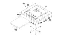
本実施形態のメモリカード用コネクタ10は携帯端末に対して着脱可能なmicroSIMカードMC用のコネクタである。
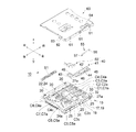
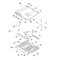
メモリカード用コネクタ10は大きな構成要素として下部ハウジング15、スライダ40、カムバー55、シェル60、及び、圧縮コイルバネS1を具備している。
Hereinafter, an embodiment of the present invention will be described with reference to the accompanying drawings. In the following description, front and rear, up and down, and left and right directions are based on the directions of the arrows shown in the drawings.
The
The
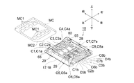
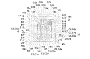
平面視略矩形の下部ハウジング15は、左側部構成片17と、右側部構成片22と、8つのコンタクトC1〜C8と、絶縁性かつ耐熱性の合成樹脂料からなるインシュレータ27と、を具備する一体成形品である。
左側部構成片17、右側部構成片22、及びコンタクトC1〜C8は一枚の金属板をプレス成形することにより構成したものであり、図7、図8に示すように下部ハウジング15の構成前(プレス成形直後)においては単一の金属製一体部材16の一部をそれぞれ構成している。金属製一体部材16は、左側部構成片17、右側部構成片22、及びコンタクトC1〜C8の一体物の外周側に位置する略方形の枠体であるキャリア16aと、キャリア16aと当該一体物とを接続する複数の接続アーム部16cと、を具備している。キャリア16aには複数の搬送用孔16bが貫通孔として形成してある。
左側部構成片17は、水平板状のスライダ支持部18と、スライダ支持部18の左側縁部から上方に立ち上がった左側壁部19と、左側壁部19の左側面に突設した3つの左側係止突起20と、を具備するものである。
右側部構成片22は、水平板状の底部構成部23と、底部構成部23の右側縁部から上方に立ち上がった右側壁部24と、右側壁部24の右側面に突設した3つの右側係止突起25と、を具備するものである。
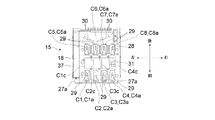
コンタクトC1〜C8は、その基端部(前端部)から後ろ斜め上方に向かって延びる接触片C1a〜C8aと、金属製一体部材16の後端部に突設した、スライダ支持部18及び底部構成部23の一段下方に位置し、かつ、接触片C1a〜C8aとそれぞれ連続するテール片C1b〜C8b(信号用テール片)と、を一体的に有している。接触片C1aとテール片C1bの間、接触片C2aとテール片C2bの間、接触片C3aとテール片C3bの間、及び接触片C4aとテール片C4bの間を構成する部分はそれぞれ中間部C1c、C2c、C3c、C4cを構成している。
さらに金属製一体部材16は、隣接する左側部構成片17、右側部構成片22、及びコンタクトC1〜C8を互いに接続する計16個の切断ブリッジB1〜B16を有している。
The
The left
The
The right
The contacts C1 to C8 have contact pieces C1a to C8a extending obliquely upward and rearward from the base end portion (front end portion), and a
Further, the metal integrated
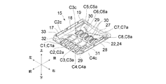
この金属製一体部材16は、各搬送用孔16bに搬送装置(図示略)のスプロケットを係合させ、各スプロケットを回転させることにより前方に搬送される。そして所定位置まで搬送されたときに金属製一体部材16の上下に位置する一対の金型からなる一次成形型(図示略)が閉じ、一次成形型内に金属製一体部材16を収納する。さらに金属製一体部材16の搬送用孔16bに対して一次成形型に設けた多数の支持用ピン(図示略)が嵌合することにより金属製一体部材16が一次成形型内で固定される。そして一次成形型内で金属製一体部材16に対して耐熱性及び絶縁性の合成樹脂材料を射出一体成形を行うことにより、金属製一体部材16に対して合成樹脂製のインシュレータ27を一体化する。インシュレータ27は、下部ハウジング15の底面部を構成する底板部28と、カムバー支持部32と、後部壁34と、を備えている。後部壁34には後部係止突起34aが突設してある。またインシュレータ27の前端の左右両角部には逃げ用凹部27aがそれぞれ凹設してある。
図示するようにコンタクトC1〜C8の接触片C1a〜C8a及びテール片C1b〜C8bを除く部分の一部(例えば、中間部C1c〜C4cの一部と切断ブリッジB3〜B6の一部)は底板部28の内部(底板部28の上面と下面の間)に埋設してある。即ち、中間部C1c〜C4cと切断ブリッジB3〜B6は、底板部28の上面より下方かつ底板部28の下面より上方に位置している。さらにテール片C1b〜C8bはインシュレータ27の下面より一段低い位置に位置している。
底板部28には、接触片C1a〜C8aを露出させるための計8個のコンタクト露出孔29と、切断ブリッジB1〜B16を露出させるための計15個の円形孔からなるブリッジ露出孔30と、中間部C1c〜C4cの一部及び切断ブリッジB3〜B6の一部を露出させる貫通孔31と、が形成してある。図示するように貫通孔31は、左右方向(microSIMカードMCのメモリカード用コネクタ10に対する挿脱方向及びmicroSIMカードMCの厚み方向に対して直交する一方向)に並んだ接触片C1a〜C4a(第一接触片群)と当該一方向に並んだ接触片C5a〜C8a(第二接触片群)の間に位置し、かつ平面視で接触片C1a〜C5aと前後方向に並ぶ、前後長より左右長が長い単一の長孔である。下部ハウジング15の左側部の前端部を構成するカムバー支持部32の上面には下方に向かって凹むカムバー支持溝33が形成してある。下部ハウジング15の後端部を構成する後部壁34の左側部には前方に向かって突出するバネ支持用突起35が形成してある。さらに、図示するように左側部構成片17のスライダ支持部18は、底板部28(の左側縁部)に対して一段下方に位置している(左側部構成片17の上面と底板部28の上面の間には段差がある)。左側壁部19の右側面と底板部28の左側面とスライダ支持部18の上面とで囲まれた部分はスライド溝37を構成している。
射出一体成形時においては、左側部構成片17、右側部構成片22、及びコンタクトC1〜C8は、切断ブリッジB1〜B16によって互いに一体化しているので、左側部構成片17、右側部構成片22、及びコンタクトC1〜C8が射出一体以前の工程および射出一体成形工程(金型内)でばらけたり位置ずれしたりすることはない。
上記一次成形型を開いて該一次成形型から金属製一体部材16とインシュレータ27の一体物を取り出した後に、当該一体物を上記搬送装置を利用して前方の所定位置まで搬送する。そして、当該所定位置に配設した切断装置(図示略)によって、各ブリッジ露出孔30から露出する切断ブリッジB1、B2、B7〜B16を物理的に切断(切断ブリッジB1、B2、B7〜B16を二つに分断して、分断された二つの部位を互いに離間させる)し、かつ貫通孔31から露出する切断ブリッジB3〜B6を物理的に切断し、さらに各接続アーム部16c(のキャリア16aと反対側の端部)を物理的に切断すれば、図11、図12に示す下部ハウジング15が得られる。図示するように下部ハウジング15の内部空間は左側壁部19、右側壁部24、底板部28、後部壁34、及び後述するシェル60によって囲まれた収納部38となっている。
The metal integrated
As shown in the drawing, a part of the contacts C1 to C8 except for the contact pieces C1a to C8a and the tail pieces C1b to C8b (for example, a part of the intermediate parts C1c to C4c and a part of the cutting bridges B3 to B6) is a bottom plate part. It is embedded in the inside of 28 (between the upper surface and the lower surface of the bottom plate portion 28). That is, the intermediate portions C1c to C4c and the cutting bridges B3 to B6 are located below the upper surface of the
The
At the time of injection integral molding, the left
After opening the primary forming die and taking out the integrated body of the metal integrated
スライダ40はスライダ本体41と補強部材50を一体化したものである。
耐熱性の合成樹脂材からなるスライダ本体41は、前後方向に延び、かつ、スライド溝37に対して自身の下端部がスライド自在に係合する直線状部42と、直線状部42の後端部から右側に突出する当接用端部43と、を備えている。
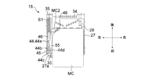
直線状部42の上面の前部には、平面視で略ハート形状をなすハートカム溝44が凹設してある。ハートカム溝44はハート形凸部45の周囲に凹設した多数の段差を有する溝であり、その後部をなし前後方向に直線的に延びる初期係合部44aと、ハート形凸部45の左側に位置する押し込み時通過部44bと、ハート形凸部45の前端部に位置する保持部44cと、ハート形凸部45の右側に位置する戻り時通過部44d、とを有している。
スライダ本体41の後部の左半部には、後方に向かって延びる円柱状のバネ支持軸46が突設してある。当接用端部43の右端部には、平面視において前後方向に対して傾斜する平面であるカード当接部49が形成してある。
金属製の補強部材50は、スライダ本体41の後部に固定状態で取り付けてある。
スライダ40は、図6及び図14に示す初期位置と、図15に示す押込位置との間を、スライド溝37に沿って前後方向にスライド可能である。さらに、スライダ40の後端部と後部壁34の左側部との間には圧縮コイルバネS1が自由状態より縮んだ(弾性変形した)状態で配設してある。圧縮コイルバネS1の前部にはバネ支持軸46が挿入してあり、圧縮コイルバネS1の後端部はバネ支持用突起35と係止している。そのため圧縮コイルバネS1からスライダ40に対して常に前向きの付勢力が及ぶので、スライダ40に対して圧縮コイルバネS1以外の外力が及ばないとき、スライダ40は初期位置に位置する。
The
The slider
A
A columnar
The
The
金属製のカムバー55は、下部ハウジング15とスライダ本体41を連係する部材である。カムバー55はその前後両端部に下向きに屈曲する前端係合突部56と後端係合突部57を有している。前端係合突部56は下部ハウジング15(カムバー支持部32)のカムバー支持溝33に対して回転可能に係合しており、後端係合突部57はスライダ本体41のハートカム溝44に相対移動可能に係合している。
The
スライダ40、カムバー55、及び圧縮コイルバネS1を収納する下部ハウジング15の上部はシェル60によって覆われている。
金属板のプレス成形品であるシェル60の左右両側壁にはそれぞれ3つの係止孔61が穿設してある。シェル60の天井部の後端には下方に向かって延びる垂下片62が突設してあり、垂下片62には係止孔63が穿設してある。シェル60は、その天井面によって下部ハウジング15の上面を覆い、かつ係止孔61及び係止孔63を下部ハウジング15の左側係止突起20、右側係止突起25、及び後部係止突起34aに対してそれぞれ係合することにより下部ハウジング15に対して装着する。さらにシェル60の天井部の前側の左側角部近傍には、プレス成形時に成形されるカムバー付勢用板バネ64が設けてある。カムバー付勢用板バネ64は、その基端部(前端部)から後斜め下方に向かって延びる片持ち式の板バネであり、カムバー付勢用板バネ64が自由状態にあるとき、カムバー付勢用板バネ64はシェル60の天井面より下方に位置する。そのためシェル60を下部ハウジング15に装着すると、カムバー付勢用板バネ64がカムバー55を常に下部ハウジング15の底面側(下向き)に向けて付勢するため、カムバー55の前端係合突部56とカムバー支持溝33の係合状態、及び、後端係合突部57とハートカム溝44の係合状態が常に維持される。さらにシェル60の左右両側壁の前端下縁部には、内向き水平のテール片65(接地用テール片)(固定部)がそれぞれ突設してある。左右のテール片65は左右の逃げ用凹部27a内に位置しており、テール片65の下面はテール片C1b〜C8bの下面と略同一平面上に位置している。
The upper portion of the
Three locking
メモリカード用コネクタ10は、回路基板CB(図1の仮想線参照)の上面(回路形成面)に実装する。具体的には、メモリカード用コネクタ10の上方に位置する吸引手段(図示略)によってシェル60の上面を吸着し、吸引手段を上方へ移動せることによりメモリカード用コネクタ10を一旦上方へ移動させる。そして該吸引手段によりメモリカード用コネクタ10を回路基板CBの上方に移動させた後に、画像認識手段(図示略)によってテール片C1b〜C8bの位置を確認しながら、テール片C1b〜C8bを回路基板CB上の回路パターン(図示略)に塗布したはんだペースト上に載置し、さらにシェル60の左右のテール片65を回路基板CB上の接地パターン(図示略)に塗布したはんだペースト上に載置する。そしてリフロー炉において各はんだペーストを加熱溶融(リフロー)し、テール片C1b〜C8b及びテール片65を上記各パターンにはんだ付けする。
The
メモリカード用コネクタ10の回路基板CBに対する実装状態を確実にするために、メモリカード用コネクタ10はリフローによる熱が印加された後に、空冷により常温になる。
インシュレータ27を正規形状(設計形状)通りに成形したときにインシュレータ27に残留応力が発生すると、その後の熱変化(リフローによって高温化したり、空冷によって常温に戻ること)によって残留応力が解放され、底板部28の前部(底板部28の貫通孔31より接触片C1a〜C4a側に位置する部位)と底板部28の後部(底板部28の貫通孔31より接触片C5a〜C8a側に位置する部位)が(正規形状から)変形しようとする。さらに、上記熱変化によって生じる底板部28の前部と後部の熱収縮の程度(変形量)には差が生じ易い。そのため、仮にインシュレータ27の底板部28に貫通孔31を形成しない場合は、(残留応力の解放や熱収縮の差に起因して生じる)底板部28の前部と後部の変形しようとする力によって、底板部28(インシュレータ27)全体が大きく反ったり、捩れるおそれがある。
しかし本実施形態では、底板部28の前部と後部が(正規形状から)変形しようとする力を、底板部28に形成した(底板部28の前部と後部の間に位置する)貫通孔31で吸収する(逃がす)ので、底板部28の前部と後部の変形しようとする力が互いに影響し合うことがない。そのため、インシュレータ27(メモリカード用コネクタ10)全体の反りや捩れを抑制できる。
さらにコンタクトC1〜C8の接触片C1a〜C8a及びテール片C1b〜C8bを除く部分の一部(例えば、中間部C1c〜C4cの一部と切断ブリッジB3〜B6の一部)が底板部28の内部(底板部28の上面と下面の間)に埋設してあるので、仮に貫通孔31を形成することなく底板部28を薄型化すると、底板部28の成形時(射出一体成形時に)に貫通孔31に対応する部分を構成する合成樹脂材料が中間部C1c〜C4cの周辺に回り込み難くなるので、合成樹脂材料が硬化したときに(底板部28の)当該部分に発生する残留応力にばらつきが出てしまう(隣接する中間部C1c〜C4cの間に位置する部位の残留応力と、中間部C1c〜C4cの周辺で硬化した部位の残留応力に差が出てしまう)。そのため貫通孔31を形成することなく底板部28を薄型化すると、下部ハウジング15の製造時点で底板部28に反りや捩れが生じるおそれがある。しかし本実施形態のように、中間部C1c〜C4cの一部及び切断ブリッジB3〜B6の一部を露出させる貫通孔31を底板部28に形成する場合は、このような問題が発生しないので、下部ハウジング15の製造時点で底板部28に反りや捩れが生じるおそれが小さくなる。
従って、底板部28(インシュレータ27)の後端部側にテール片C1b〜C8bが位置する一方で、底板部28(インシュレータ27)の前端部側にシェル60のテール片65が位置するために、テール片C1b〜C8bとテール片65が前後方向(microSIMカードMCの挿脱方向)に大きく離間しているものの、テール片C1b〜C8bと回路パターンの間、及び、テール片65と接地パターンの間ではんだ付け不良が発生するおそれは小さい。
In order to ensure the mounting state of the
If residual stress is generated in the
However, in this embodiment, a through-hole (located between the front and rear portions of the bottom plate portion 28) is formed in the
Further, a part of the contacts C1 to C8 excluding the contact pieces C1a to C8a and the tail pieces C1b to C8b (for example, a part of the intermediate parts C1c to C4c and a part of the cutting bridges B3 to B6) is inside the
Accordingly, since the tail pieces C1b to C8b are located on the rear end side of the bottom plate portion 28 (insulator 27), the
次に以上構成のメモリカード用コネクタ10にmicroSIMカードMCを挿脱するときの動作について説明する。
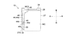
平面視略矩形をなすmicroSIMカードMCの下面には8つの端子MC1が形成してある。またmicroSIMカードMCの4つの角部のうちの一つ(左後方の角部)は、当該角部を通る対角線に対して略直交する直線によって切り落とされた(切り欠かれた)切断角部MC2を構成している。
Next, an operation when the micro SIM card MC is inserted into and removed from the
Eight terminals MC1 are formed on the lower surface of the microSIM card MC that has a substantially rectangular shape in plan view. Also, one of the four corners (left rear corner) of the microSIM card MC is cut off (cut out) by a straight line substantially orthogonal to a diagonal passing through the corner. Is configured.
メモリカード用コネクタ10にmicroSIMカードMCを挿入していない状態においては、圧縮コイルバネS1の付勢力によってスライダ40は初期位置に位置し、さらにカムバー55の後端係合突部57がハートカム溝44の初期係合部44aに係合する(図6、図14参照)。
この状態で正規姿勢(端子MC1が下方に位置し、左側後方の角部が切断角部MC2となる姿勢)としたmicroSIMカードMCを収納部38の前面開口部から収納部38内に挿入し、microSIMカードMCをさらに後方に押し込むと、切断角部MC2がスライダ本体41(当接用端部43)のカード当接部49に当接するので、microSIMカードMCとスライダ40が一体化する(図14参照)。
In a state where the micro SIM card MC is not inserted into the
In this state, the microSIM card MC in a normal posture (the posture in which the terminal MC1 is positioned below and the left rear corner becomes the cut corner MC2) is inserted into the
この状態からmicroSIMカードMCをさらに後方に押圧すると、スライダ40が圧縮コイルバネS1の付勢力に抗して(圧縮コイルバネS1を圧縮方向に弾性変形させながら。図15では圧縮コイルバネS1の図示は省略)後方にスライドするので、初期係合部44aの中央部に係合していたカムバー55の後端係合突部57が初期係合部44aの前部及び押し込み時通過部44bを前方に向かって移動する(初期係合部44aの前部と押し込み時通過部44bに対して順に係合する)。そして、カムバー55の後端係合突部57が押し込み時通過部44bの前端部(ハート形凸部45の前方に位置する部分)まで移動したときに、スライダ40は押込位置に到達する(図15参照)。
スライダ40が押込位置に到達した後にmicroSIMカードMCに対する後方への押圧力を解除すると、圧縮コイルバネS1の付勢力によって前方に押圧された(押し戻された)スライダ本体41の保持部44cがカムバー55の後端係合突部57に対して係合するので、スライダ40は押込位置に保持される(スライダ40の前方へのスライドが規制される)。スライダ40が押込位置に到達すると、microSIMカードMCの各端子MC1が対応するコンタクトC1〜C8の接触片C1a〜C8aとそれぞれ接触するので、コンタクトC1〜C8(テール片C1b〜C8b)を介して、メモリカード用コネクタ10に挿入したmicroSIMカードMCと回路基板CBが電気的に導通する。
When the micro SIM card MC is further pushed backward from this state, the
When the backward pressing force against the micro SIM card MC is released after the
スライダ40が押込位置に保持された状態で、microSIMカードMCを再度圧縮コイルバネS1の付勢力に抗して後方に押し込んだ後にmicroSIMカードMCに対する後方への押圧力を解除すると、圧縮コイルバネS1による前向きの付勢力により後端係合突部57が保持部44cから後方に離れた後に戻り時通過部44d側に移動し(係合し)、戻り時通過部44dを通って初期係合部44aの中央部まで自動的に移動する。従って、スライダ40は初期位置に復帰する(図14参照)。そのためmicroSIMカードMCを手で掴んでメモリカード用コネクタ10から前方に引き出すことが可能になる。
When the micro SIM card MC is pushed back against the urging force of the compression coil spring S1 in the state where the
以上説明したように本実施形態のメモリカード用コネクタ10は底板部28に反りや捩れが生じ難いため、コンタクトC1〜C8のテール片C1b〜C8b及びシェル60のテール片65と回路基板CBとの間のはんだ付け不良を発生し難くすることが可能である。
As described above, the
またシェル60が回路基板CBの接地パターンと接地導通するので、コンタクトC1〜C8に外部ノイズが入ったり、コンタクトC1〜C8のノイズがメモリカード用コネクタ10の外部に漏れるのを効果的に抑制できる。
Further, since the
本発明は上記実施形態に限定されるものではなく、様々な変形を施しながら実施可能である。
例えば、micoSIMカードMC以外のメモリカード(例えば、microSDカード、SIMカードなど)を挿脱するためのメモリカード用コネクタに本発明を適用してもよい。
さらに、メモリカード用コネクタ10を携帯端末以外の機器(例えば、PDA、パーソナルコンピュータ、デジタルカメラ、デジタルビデオカメラ等)に実装してもよい。
The present invention is not limited to the above-described embodiment, and can be implemented with various modifications.
For example, the present invention may be applied to a memory card connector for inserting / removing a memory card (for example, a microSD card, a SIM card, etc.) other than the micoSIM card MC.
Furthermore, the
また下部ハウジング15に設けるコンタクトの数は複数であれば、8本以外であってもよい。コンタクトの数をいくつにする場合であっても、一方のコンタクト(群)の接触片を底板部28の前部側に位置させ、他方のコンタクト(群)の接触片を底板部28の後部側に位置させ、さらに前側の接触片(群)と後方の接触片(群)の間に位置しかつ前方の全ての接触片(群)及び後方の全ての接触片(群)と前後方向に並ぶ(左右寸法が長い)単一の貫通孔31を底板部28に形成する。
また、シェル60を省略した上で、インシュレータ27の前端部に固定した固定部(インシュレータに固定した固定金具や、コンタクトの前端部から突出する(テール片C1b〜C8bと反対側の)テール片など)を回路基板CBにはんだ付け(実装)してもよい。
さらにコンタクトC1〜C8のテール片C1b〜C8bをインシュレータ27の前端部側に位置させ、固定部(シェル60のテール片65、固定金具、コンタクトのテール片C1b〜C8bと反対側のテール片など)をインシュレータ27の後端部側に位置させてもよい。
The number of contacts provided in the
Further, after the
Further, the tail pieces C1b to C8b of the contacts C1 to C8 are positioned on the front end side of the
10 メモリカード用コネクタ
15 下部ハウジング
16 金属製一体部材
16a キャリア
16b 搬送用孔
16c 接続アーム部
17 左側部構成片
18 スライダ支持部
19 左側壁部
20 左側係止突起
22 右側部構成片
23 底部構成部
24 右側壁部
25 右側係止突起
27 インシュレータ
27a 逃げ用凹部
28 底板部
29 コンタクト露出孔
30 ブリッジ露出孔
31 貫通孔
32 カムバー支持部
33 カムバー支持溝
34 後部壁
34a 後部係止突起
35 バネ支持用突起
37 スライド溝
38 収納部
40 スライダ
41 スライダ本体
42 直線状部
43 当接用端部
44 ハートカム溝
44a 初期係合部
44b 押し込み時通過部
44c 保持部
44d 戻り時通過部
45 ハート形凸部
46 バネ支持軸
49 正規挿入時当接部
55 カムバー
56 前端係合突部
57 後端係合突部
60 シェル
61 係止孔
62 垂下片
63 係止孔
64 カムバー付勢用板バネ
65 テール片(接地用テール片)(固定部)
B1〜B16 切断ブリッジ
C1〜C8 コンタクト
C1a〜C8a 接触片
C1b〜C8b テール片(信号用テール片)
C1c〜C4c 中間部
CB 回路基板
MC microSIMカード(メモリカード)
MC1 端子
MC2 切断角部
S1 圧縮コイルバネ
DESCRIPTION OF
B1 to B16 Cutting bridge C1 to C8 Contact C1a to C8a Contact piece C1b to C8b Tail piece (signal tail piece)
C1c to C4c Intermediate part CB Circuit board MC microSIM card (memory card)
MC1 Terminal MC2 Cutting corner S1 Compression coil spring
Claims (3)
上記インシュレータに取り付けた、上記回路基板に実装可能な固定部;及び
上記インシュレータに支持された、上記インシュレータの内部空間に挿入したメモリカードの端子と電気的に導通しかつ上記内部空間内に位置する接触片、及び上記回路基板の回路パターンに実装可能な信号用テール片、をそれぞれ有する金属製の第1のコンタクト群及び第2のコンタクト群;
を備え、
上記インシュレータの上記挿脱方向の一方の端部側に上記固定部と上記信号用テール片の一方が配設され、かつ上記インシュレータの上記挿脱方向の他方の端部側に上記固定部と上記信号用テール片の他方が配設され、
上記第1のコンタクト群の上記接触片が、上記メモリカードの上記内部空間に対する挿脱方向及び該メモリカードの厚み方向に対して直交する一方向に並びかつ上記固定部と上記信号用テール片の間に位置する第一接触片群を構成し、
上記第2のコンタクト群の上記接触片が、上記一方向に並ぶと共に上記第一接触片群と上記挿脱方向に対向しかつ上記固定部と上記信号用テール片の間に位置する第二接触片群を構成し、
上記底板部における上記第一接触片群と上記第二接触片群の間に、上記挿脱方向の長さに比べて上記第一接触片群が並ぶ方向の長さが長い長孔で且つ単一の貫通孔が形成され、
上記長い方向の貫通孔の長さは、上記第一接触片群のうちの両端の第一接触片間の離間距離及び上記第二接触片群のうちの両端の第二接触片間の離間距離より大きく、
上記長い方向の貫通孔の両端は、上記底板部において上記第一接触片群のうちの両端の第一接触片よりも外側に位置する、
ことを特徴とするメモリカード用コネクタ。 A resin insulator having a bottom plate facing the circuit board ;
A fixing portion mounted on the insulator and mountable on the circuit board ; and electrically connected to a terminal of a memory card supported by the insulator and inserted into the inner space of the insulator and positioned in the inner space. A metal first contact group and a second contact group each having a contact piece and a signal tail piece mountable on the circuit pattern of the circuit board ;
Equipped with a,
One of the fixed portion and the signal tail piece is disposed on one end side in the insertion / removal direction of the insulator, and the fixed portion and the above-mentioned one end side in the insertion / removal direction of the insulator The other of the signal tail pieces is disposed ,
The contact pieces of the first contact group are arranged in one direction perpendicular to the insertion / removal direction of the memory card with respect to the internal space and the thickness direction of the memory card, and between the fixing portion and the signal tail piece. Constituting the first contact piece group located between,
The contact pieces of the second contact group are arranged in the one direction and face the first contact piece group in the insertion / removal direction and are located between the fixing portion and the signal tail piece. Make up a group,
Between the first contact piece group and the second contact piece group in the bottom plate portion, a long hole having a long length in the direction in which the first contact piece group is arranged compared to the length in the insertion / removal direction, and a single hole. One through hole is formed ,
The length of the through hole in the long direction is defined as a distance between first contact pieces at both ends of the first contact piece group and a distance between second contact pieces at both ends of the second contact piece group. Bigger,
Both ends of the through hole in the long direction are located outside the first contact pieces at both ends of the first contact piece group in the bottom plate portion.
A connector for a memory card.
上記インシュレータに取り付けた、上記メモリカードを挿脱可能な収納部を上記底板部との間で構成する金属製のシェルを備え、
上記固定部が、上記シェルに設けた、上記回路基板の接地パターンに実装可能な接地用テール片であるメモリカード用コネクタ。 The memory card connector according to claim 1,
A metal shell is provided between the bottom plate portion and a storage portion that is attached to the insulator and into which the memory card can be inserted and removed.
A memory card connector, wherein the fixing portion is a grounding tail piece that can be mounted on the grounding pattern of the circuit board provided on the shell.
上記コンタクトが、上記接触片と上記信号用テール片の間に位置しかつ上記底板部の内部に位置する中間部を備え、
上記貫通孔が上記中間部の一部を露出させるメモリカード用コネクタ。 The memory card connector according to claim 1 or 2,
The contact includes an intermediate portion located between the contact piece and the signal tail piece and located inside the bottom plate portion;
A memory card connector in which the through hole exposes a part of the intermediate portion.
Priority Applications (2)
| Application Number | Priority Date | Filing Date | Title |
|---|---|---|---|
| JP2013034959A JP5774039B2 (en) | 2013-02-25 | 2013-02-25 | Memory card connector |
| KR1020130054339A KR101437527B1 (en) | 2013-02-25 | 2013-05-14 | Conncetor for memmory card |
Applications Claiming Priority (1)
| Application Number | Priority Date | Filing Date | Title |
|---|---|---|---|
| JP2013034959A JP5774039B2 (en) | 2013-02-25 | 2013-02-25 | Memory card connector |
Publications (2)
| Publication Number | Publication Date |
|---|---|
| JP2014165019A JP2014165019A (en) | 2014-09-08 |
| JP5774039B2 true JP5774039B2 (en) | 2015-09-02 |
Family
ID=51615458
Family Applications (1)
| Application Number | Title | Priority Date | Filing Date |
|---|---|---|---|
| JP2013034959A Expired - Fee Related JP5774039B2 (en) | 2013-02-25 | 2013-02-25 | Memory card connector |
Country Status (2)
| Country | Link |
|---|---|
| JP (1) | JP5774039B2 (en) |
| KR (1) | KR101437527B1 (en) |
Families Citing this family (1)
| Publication number | Priority date | Publication date | Assignee | Title |
|---|---|---|---|---|
| CN105826730A (en) * | 2015-09-09 | 2016-08-03 | 维沃移动通信有限公司 | Card combination connection device and electronic equipment |
Family Cites Families (7)
| Publication number | Priority date | Publication date | Assignee | Title |
|---|---|---|---|---|
| KR100741009B1 (en) * | 2005-12-16 | 2007-07-20 | 한국몰렉스 주식회사 | Dual card type connector of mobile phone |
| JP2007273233A (en) * | 2006-03-31 | 2007-10-18 | Fujitsu Ltd | Socket, circuit component with socket, and information processing device provided with circuit component |
| JP5044347B2 (en) | 2007-09-25 | 2012-10-10 | 日本圧着端子製造株式会社 | Card connector |
| JP2010192407A (en) * | 2009-02-20 | 2010-09-02 | Alps Electric Co Ltd | Card connector and method of manufacturing the same |
| JP5457888B2 (en) | 2010-03-04 | 2014-04-02 | 第一電子工業株式会社 | Card connector and card connector manufacturing method |
| JP2012114089A (en) | 2010-11-22 | 2012-06-14 | Hon Hai Precision Industry Co Ltd | Card connector |
| JP5582995B2 (en) * | 2010-12-14 | 2014-09-03 | 新光電気工業株式会社 | socket |
-
2013
- 2013-02-25 JP JP2013034959A patent/JP5774039B2/en not_active Expired - Fee Related
- 2013-05-14 KR KR1020130054339A patent/KR101437527B1/en active
Also Published As
| Publication number | Publication date |
|---|---|
| JP2014165019A (en) | 2014-09-08 |
| KR101437527B1 (en) | 2014-10-30 |
Similar Documents
| Publication | Publication Date | Title |
|---|---|---|
| JP5808763B2 (en) | Memory card connector | |
| JP5735934B2 (en) | Memory card connector | |
| US9318837B2 (en) | Electrical connector | |
| JP4918105B2 (en) | Tray card connector | |
| KR20150030624A (en) | Card Connector | |
| US20160248184A1 (en) | Card holding member and card connector | |
| TWI618306B (en) | Electrical connector | |
| US9558380B2 (en) | Card connector | |
| JP2002289295A (en) | Card connector | |
| US20170070014A1 (en) | Connector | |
| JP2017107711A (en) | connector | |
| US9004934B2 (en) | Card edge connector | |
| JP5774039B2 (en) | Memory card connector | |
| JP2002289296A (en) | Card connector | |
| KR20130032518A (en) | An electric connector for flexible printed cirecuit | |
| WO2015190181A1 (en) | Connector for memory card | |
| JP2015185422A (en) | card connector | |
| KR101326533B1 (en) | Connector for memory card | |
| US7866994B1 (en) | Card connector | |
| JP5980140B2 (en) | Card connector | |
| JP5993672B2 (en) | Electrical connector | |
| JP2018041578A (en) | Card connector | |
| KR101086150B1 (en) | Connector for memory card | |
| JP2004273338A (en) | Connector for card | |
| KR100703045B1 (en) | Memory card connecter and its assembly method |
Legal Events
| Date | Code | Title | Description |
|---|---|---|---|
| A621 | Written request for application examination |
Free format text: JAPANESE INTERMEDIATE CODE: A621 Effective date: 20141126 |
|
| RD04 | Notification of resignation of power of attorney |
Free format text: JAPANESE INTERMEDIATE CODE: A7424 Effective date: 20150130 |
|
| A977 | Report on retrieval |
Free format text: JAPANESE INTERMEDIATE CODE: A971007 Effective date: 20150410 |
|
| A131 | Notification of reasons for refusal |
Free format text: JAPANESE INTERMEDIATE CODE: A131 Effective date: 20150414 |
|
| A521 | Request for written amendment filed |
Free format text: JAPANESE INTERMEDIATE CODE: A523 Effective date: 20150526 |
|
| TRDD | Decision of grant or rejection written | ||
| A01 | Written decision to grant a patent or to grant a registration (utility model) |
Free format text: JAPANESE INTERMEDIATE CODE: A01 Effective date: 20150616 |
|
| A61 | First payment of annual fees (during grant procedure) |
Free format text: JAPANESE INTERMEDIATE CODE: A61 Effective date: 20150630 |
|
| R150 | Certificate of patent or registration of utility model |
Ref document number: 5774039 Country of ref document: JP Free format text: JAPANESE INTERMEDIATE CODE: R150 |
|
| S111 | Request for change of ownership or part of ownership |
Free format text: JAPANESE INTERMEDIATE CODE: R313111 |
|
| R350 | Written notification of registration of transfer |
Free format text: JAPANESE INTERMEDIATE CODE: R350 |
|
| LAPS | Cancellation because of no payment of annual fees |
