JP5773435B2 - Charger - Google Patents
Charger Download PDFInfo
- Publication number
- JP5773435B2 JP5773435B2 JP2011233821A JP2011233821A JP5773435B2 JP 5773435 B2 JP5773435 B2 JP 5773435B2 JP 2011233821 A JP2011233821 A JP 2011233821A JP 2011233821 A JP2011233821 A JP 2011233821A JP 5773435 B2 JP5773435 B2 JP 5773435B2
- Authority
- JP
- Japan
- Prior art keywords
- correction
- output
- power value
- ripple
- value
- Prior art date
- Legal status (The legal status is an assumption and is not a legal conclusion. Google has not performed a legal analysis and makes no representation as to the accuracy of the status listed.)
- Expired - Fee Related
Links
Images
Landscapes
- Dc-Dc Converters (AREA)
Description
本発明は、交流電源から供給された交流電力を直流電力に変換してバッテリーに供給する充電装置に関する。 The present invention relates to a charging device that converts AC power supplied from an AC power source into DC power and supplies the DC power to a battery.
一般に、充電装置は、交流電源から供給された交流電力を整流および平滑して直流入力電力を生成する整流平滑回路と、直流入力電力をスイッチ手段でスイッチングして直流出力電力に変換するDC/DCコンバータ回路と、スイッチ手段のデューティ比を制御するスイッチ制御回路とを備えている。 Generally, a charging device includes a rectifying / smoothing circuit that rectifies and smoothes AC power supplied from an AC power source to generate DC input power, and DC / DC that switches DC input power to switch to DC output power by switching means. A converter circuit and a switch control circuit for controlling the duty ratio of the switch means are provided.
この充電装置は、DC/DCコンバータ回路から出力される直流出力電力の電力値と目標電力値との偏差に応じて、スイッチ手段のデューティ比を制御することにより、バッテリーに安定した直流出力電力を供給するものである。 This charging device controls the duty ratio of the switch means according to the deviation between the power value of the DC output power output from the DC / DC converter circuit and the target power value, thereby providing a stable DC output power to the battery. To supply.
ところで、上記のようにスイッチ手段を備えた充電装置では、直流出力電力にリプルが含まれる場合がある。直流出力電力にリプルが含まれると、バッテリー寿命に影響を与え、ひいてはユーザーに過大な保守費用の負担を課すことになる。
このため、充電装置では、直流出力電力におけるリプルを低減させる必要がある。
By the way, in the charging device provided with the switch means as described above, ripple may be included in the DC output power. If ripples are included in the DC output power, it will affect the battery life and, in turn, impose an excessive maintenance cost burden on the user.
For this reason, in a charging device, it is necessary to reduce the ripple in DC output power.
直流出力電力におけるリプルを低減させる方法としては、従来から、DC/DCコンバータ回路に入力される直流入力電圧を検出し、該直流入力電圧におけるリプルに応じてスイッチ手段のデューティ比を制御するフィードフォワード制御方式の方法が知られている(例えば、特許文献1参照)。 As a method for reducing the ripple in the DC output power, conventionally, a feed-forward that detects the DC input voltage input to the DC / DC converter circuit and controls the duty ratio of the switch means according to the ripple in the DC input voltage. A control method is known (see, for example, Patent Document 1).
この従来の方法では、直流入力電圧が増加した場合にはデューティ比を減少させる一方、直流入力電圧が減少した場合にはデューティ比を増加させることで、直流出力電力におけるリプルを低減させている。 In this conventional method, when the DC input voltage is increased, the duty ratio is decreased, while when the DC input voltage is decreased, the duty ratio is increased to reduce the ripple in the DC output power.
しかしながら、上記従来の方法では、フィードフォワード制御方式を採用しているので、負荷変動により直流出力電力が増減すると、その増減分がフィードバックされて直流入力電力におけるリプルが見かけ上増減してしまう。
すなわち、従来の方法では、負荷変動が起きた場合に見かけ上増減したリプルに応じてスイッチ手段のデューティ比が制御されてしまうので、DC/DCコンバータ回路から出力される直流出力電力が不安定になってしまうという問題があった。
However, since the conventional method employs the feedforward control method, when the DC output power increases or decreases due to load fluctuations, the increase or decrease is fed back and the ripple in the DC input power apparently increases or decreases.
That is, in the conventional method, when the load fluctuation occurs, the duty ratio of the switch means is controlled according to the ripple that is apparently increased or decreased, so that the DC output power output from the DC / DC converter circuit becomes unstable. There was a problem of becoming.
本発明は上記事情に鑑みてなされたものであって、その課題とするところは、リプルの低減を図るとともに、バッテリーに安定した直流出力電力を供給することができる充電装置を提供することにある。 The present invention has been made in view of the above circumstances, and an object of the present invention is to provide a charging device capable of reducing ripple and supplying stable DC output power to a battery. .
上記課題を解決するために、本発明に係る充電装置は、交流電源から供給された交流電力を整流および平滑して直流入力電力を生成する整流平滑回路と、直流入力電力をスイッチ手段でスイッチングして直流出力電力に変換してバッテリーに出力するDC/DCコンバータ回路と、バッテリーへの出力電力値が予め設定された設定電力値となるようにスイッチ手段のデューティ比をフィードバック制御するスイッチ制御回路とを備えた充電装置であって、
交流電力の極性が反転するタイミングで同期信号を出力する同期検出回路をさらに備え、
スイッチ制御回路は、
フィードバック制御によりスイッチ手段のオン/オフ制御量を算出する制御量算出部と、
同期信号に同期するとともに、バッテリーに出力される出力リプル波形を反転させ、かつ振幅の大きさを1に正規化した補正基本パターンに基づいて補正量を算出する補正量算出部と、
を有し、
制御量算出部で算出されたオン/オフ制御量に補正量算出部で算出された補正量を加算してデューティ比を求めるリプル補正処理を行い、
補正量算出部は、
バッテリーへの出力電力値を算出する電力値算出手段と、
予め求めていたリプル補正処理をしない場合のバッテリーへの出力電力値とリプル値との相互関係を示す相互関係データに基づいて電力値算出手段で算出された出力電力値における補正ゲインを算出する補正ゲイン算出手段と、
を有し、
補正基本パターンに補正ゲインを乗算することにより、補正量を算出することを特徴とする。
In order to solve the above-described problems, a charging device according to the present invention includes a rectifying / smoothing circuit that rectifies and smoothes AC power supplied from an AC power source to generate DC input power, and switches DC input power with a switch unit. A DC / DC converter circuit for converting to DC output power and outputting to the battery, and a switch control circuit for feedback controlling the duty ratio of the switch means so that the output power value to the battery becomes a preset set power value; A charging device comprising:
It further includes a synchronization detection circuit that outputs a synchronization signal at the timing when the polarity of the AC power is inverted,
The switch control circuit
A control amount calculation unit for calculating an on / off control amount of the switch means by feedback control;
A correction amount calculation unit that calculates a correction amount based on a correction basic pattern that is synchronized with the synchronization signal, inverts the output ripple waveform output to the battery , and normalizes the amplitude magnitude to 1 ,
Have
By adding the correction amount calculated in the correction amount calculation unit on / off control amount calculated by the control amount calculating section have rows ripple correction processing for determining the duty ratio,
The correction amount calculation unit
Power value calculating means for calculating the output power value to the battery;
Correction for calculating a correction gain in the output power value calculated by the power value calculation means based on the correlation data indicating the correlation between the output power value to the battery and the ripple value when the ripple correction processing obtained in advance is not performed Gain calculation means;
Have
The correction amount is calculated by multiplying the correction basic pattern by the correction gain .
この構成によれば、制御量算出部でバッテリーへの出力電力値が設定電力値となるようにフィードバック制御されてスイッチ手段のオン/オフ制御量が算出されるが、当該オン/オフ制御量に補正量算出部で算出された補正量を加算してデューティ比が求められる。
ここで、交流電力の極性が反転するタイミングで同期信号を出力する同期検出回路を備え、補正量算出部は同期信号に同期するとともに、バッテリーに出力される出力リプル波形を反転させた補正基本パターンに基づいて補正量を算出している。
つまり、出力に含まれるリプルをキャンセルするように補正量をオン/オフ制御量に加算してデューティ比を求め、当該デューティ比によりスイッチ手段を制御している。このため、出力リプルの低減を図り、バッテリーに安定した直流出力電力を供給することができる。
さらに、この構成によれば、補正基本パターンの振幅の大きさは1に正規化されており、リプル補正処理をしない場合の出力電力値とリプル値との相互関係を示す相互関係データに基づいて出力電力値における補正ゲインを算出し、補正基本パターンに補正ゲインを乗算することにより、補正量を算出することができる。このため、出力電力値に応じた適切な補正量を算出することができ、出力リプルを確実に低減することができる。
ここで、上記相互関係データは、補正量算出部で算出された補正量を加算することなく、デューティ比を制御したときの出力電力値とリプル値との相互関係を予め求めたデータである。
According to this configuration, the control amount calculation unit performs feedback control so that the output power value to the battery becomes the set power value, and the on / off control amount of the switch unit is calculated. The duty ratio is obtained by adding the correction amounts calculated by the correction amount calculation unit.
Here, a correction basic pattern is provided that includes a synchronization detection circuit that outputs a synchronization signal at the timing when the polarity of the AC power is inverted, and the correction amount calculation unit is synchronized with the synchronization signal and the output ripple waveform output to the battery is inverted. The correction amount is calculated based on the above.
That is, the correction amount is added to the on / off control amount so as to cancel the ripple included in the output to obtain the duty ratio, and the switch means is controlled by the duty ratio. For this reason, output ripple can be reduced and stable DC output power can be supplied to the battery.
Further, according to this configuration, the magnitude of the amplitude of the correction basic pattern is normalized to 1, and based on the correlation data indicating the correlation between the output power value and the ripple value when the ripple correction process is not performed. A correction amount can be calculated by calculating a correction gain in the output power value and multiplying the correction basic pattern by the correction gain. For this reason, an appropriate correction amount according to the output power value can be calculated, and output ripple can be reliably reduced.
Here, the interrelation data is data obtained in advance with respect to the interrelationship between the output power value and the ripple value when the duty ratio is controlled without adding the correction amount calculated by the correction amount calculation unit.
上記充電装置における補正量算出部は、
少なくとも直流出力電力におけるリプル周期の1周期分の波形データからなる補正基本パターンデータを格納する補正基本パターンデータ格納手段をさらに有し、
補正基本パターンデータ格納手段に格納された補正基本パターンに補正ゲインを乗算することにより、補正量を算出することを特徴とする。
The correction amount calculation unit in the charging device is
Correction basic pattern data storage means for storing correction basic pattern data consisting of waveform data for at least one ripple period in DC output power;
The correction amount is calculated by multiplying the correction basic pattern stored in the correction basic pattern data storage means by the correction gain.
この構成によれば、少なくとも直流出力電力におけるリプル周期の1周期分の波形データからなる補正基本パターンデータに補正ゲインを乗算することにより、出力リプルを確実にキャンセルするようにデューティ比を決定することができる。 According to this configuration, the duty ratio is determined so as to surely cancel the output ripple by multiplying the correction basic pattern data including the waveform data corresponding to at least one ripple period in the DC output power by the correction gain. Can do.
さらに、上記補正量算出部は、同期検出回路から出力される同期信号と同期して、補正基本パターンデータに補正ゲインを乗算することで補正量を算出することが好ましい。 Furthermore, it is preferable that the correction amount calculation unit calculates the correction amount by multiplying the correction basic pattern data by a correction gain in synchronization with the synchronization signal output from the synchronization detection circuit.
この構成によれば、交流電源に同期してリプル補正処理を行うので、補正結果に位相ずれを生じることなく、低リプルの出力電力を安定的に供給することができる。 According to this configuration, since the ripple correction process is performed in synchronization with the AC power supply, low ripple output power can be stably supplied without causing a phase shift in the correction result.
また、上記充電装置では、バッテリーへの出力電力値と、電力値算出手段で算出された出力電力値におけるリプル値が最小となるような補正基本パターンに乗算する定数との関係を相互関係データとして予め求めておき、
補正ゲイン算出手段が、電力値算出手段で算出された出力電力値における定数を相互関係データから読み込むことで、該定数を補正ゲインとして算出してもよい。
Further, in the above charging device, the relationship between the output power value to the battery and the constant multiplied by the correction basic pattern that minimizes the ripple value in the output power value calculated by the power value calculation means is used as the correlation data. Find in advance,
The correction gain calculation means may read the constant in the output power value calculated by the power value calculation means from the correlation data to calculate the constant as the correction gain.
この構成によれば、バッテリーへの出力電力値と、電力値算出手段で算出された出力電力値におけるリプル値が最小となるような補正基本パターンに乗算する定数との関係を相互関係データとして予め求めておき、電力値算出手段で算出された出力電力値における定数を相互関係データから読み込むことで補正ゲインを算出しているので、出力電力値に応じてリプルを最小にすることができる。 According to this configuration, the relationship between the output power value to the battery and the constant that is multiplied by the correction basic pattern that minimizes the ripple value in the output power value calculated by the power value calculation means is previously stored as the correlation data. Since the correction gain is calculated by reading the constant in the output power value calculated by the power value calculation means from the correlation data, the ripple can be minimized according to the output power value.
また、上記充電装置は、DC/DCコンバータ回路から出力される直流出力電圧および直流出力電流をそれぞれ検出するための電圧検出回路および電流検出回路をさらに備え、
電力値算出手段が、電圧検出回路および電流検出回路で検出された電圧値および電流値に基づいてバッテリーへの出力電力値を算出することを特徴とする。
The charging device further includes a voltage detection circuit and a current detection circuit for detecting a DC output voltage and a DC output current output from the DC / DC converter circuit,
The power value calculation means calculates an output power value to the battery based on the voltage value and the current value detected by the voltage detection circuit and the current detection circuit.
この構成によれば、電圧検出回路および電流検出回路で検出された電圧値および電流値に基づいてバッテリーへの出力電力値を算出しているので、正確な出力電力値を算出することができる。 According to this configuration, since the output power value to the battery is calculated based on the voltage value and the current value detected by the voltage detection circuit and the current detection circuit, an accurate output power value can be calculated.
また、上記相互関係データは、バッテリーへの出力電力値とリプル値との関係を一次式で表現したものであってもよい。 The interrelation data may be a linear expression of the relationship between the output power value to the battery and the ripple value.
この構成によれば、バッテリーへの出力電力値とリプル値との関係を一次式で表現しているので、出力電力値に応じたリプル値を容易に算出することができる。 According to this configuration, since the relationship between the output power value to the battery and the ripple value is expressed by a linear expression, the ripple value according to the output power value can be easily calculated.
また、上記補正基本パターンは、DC/DCコンバータ回路の出力波形をcos関数で近似した波形であってもよい。 Further, the correction basic pattern may be a waveform obtained by approximating the output waveform of the DC / DC converter circuit by a cos function.
この構成によれば、リプル1周期の期間中のいずれのタイミングであっても同じ関数(cos関数)を用いることができ、タイミングによって関数を切り替える必要がない。 According to this configuration, the same function (cos function) can be used at any timing during one ripple period, and there is no need to switch the function according to the timing.
本発明によれば、リプルの低減を図るとともに、バッテリーに安定した直流出力電力を供給することができる充電装置を提供することができる。 According to the present invention, it is possible to provide a charging device capable of reducing ripples and supplying stable DC output power to a battery.
以下、添付図面を参照しつつ、本発明に係る充電装置の好ましい実施形態について説明する。 Hereinafter, preferred embodiments of a charging device according to the present invention will be described with reference to the accompanying drawings.
[充電装置の構成]
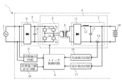
図1に、本発明の一実施形態に係る充電装置1のブロック図を示す。
同図に示すように、充電装置1は、商用交流電源等の交流電源2から供給された交流電力を整流および平滑して直流入力電力を生成する整流平滑回路3と、直流入力電力をスイッチ手段5a〜5dでスイッチングしてバッテリー19に供給すべき直流出力電力に変換するDC/DCコンバータ回路4と、バッテリー19への出力電力値が予め設定された設定電力値となるようにスイッチ手段5a〜5dのデューティ比を制御するスイッチ制御回路8とを備えている。
[Configuration of charging device]
In FIG. 1, the block diagram of the
As shown in the figure, a
整流平滑回路3は、ダイオードブリッジ回路9と、静電容量が数100μF〜数1000μFの電解コンデンサ10と、不図示の力率改善回路とを有している。
DC/DCコンバータ回路4は、IGBTやMOSFET等の4つのスイッチ手段5a〜5dからなるインバータ回路5と、トランスからなる昇圧回路6と、トランスの二次側に接続された出力回路7とを有している。
出力回路7は、ダイオードブリッジ回路11と、コイル12および平滑コンデンサ13からなるLCローパスフィルタと、数mΩのシャント抵抗14とを有している。
The rectifying / smoothing circuit 3 includes a diode bridge circuit 9, an electrolytic capacitor 10 having a capacitance of several hundreds μF to several thousand μF, and a power factor correction circuit (not shown).
The DC /
The output circuit 7 includes a
また、本実施形態に係る充電装置1は、交流電源2から供給された交流電力(交流電圧)の極性が反転するタイミングで同期信号を出力する同期検出回路15と、シャント抵抗14に流れる直流出力電流を検出する電流検出回路16と、LCローパスフィルタ経由後の直流出力電圧を検出する電圧検出回路17と、直流出力電力の目標電力値を設定する目標電力値設定回路18とを備えている。
In addition, the charging
同期検出回路15から出力された同期信号、電流検出回路16で検出された電流値、電圧検出回路17で検出された電圧値、および目標電力値設定回路18で設定された目標電力値は、スイッチ制御回路8に入力される。
The synchronization signal output from the
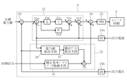
スイッチ制御回路8は、マイクロコンピュータのソフトウェアにより構成されており、図2に示すように、直流出力電流の目標電流値を算出する目標電流値演算手段20と、フィードバック制御によりスイッチ手段5a〜5dのオン/オフ制御量を算出する制御量算出部21と、直流出力電力におけるリプル値分のオン/オフ制御量に相当する補正量を算出する補正量算出部22と、オン/オフ制御量に補正量を加算する演算手段29と、スイッチ手段5a〜5dのデューティ比を制御するためのPWM信号を生成するPWM信号生成手段23と、アナログ信号をデジタル信号に変換するAD変換手段24a、24bとを有している。
The switch control circuit 8 is constituted by microcomputer software. As shown in FIG. 2, the switch control circuit 8 includes target current value calculation means 20 for calculating a target current value of the DC output current, and switch means 5a to 5d by feedback control. A control
目標電流値演算手段20は、目標電力値設定回路18で設定された目標電力値と、電圧検出回路17で検出された直流出力電圧の電圧値とに基づいて、目標電流値を算出する。
通常、バッテリー19は極低抵抗であるため直流出力電圧はバッテリー電圧とほぼ等しくなる。また、直流出力電圧は、少なくともフィードバック制御周期の間は一定である。
このため、「目標電力値/直流出力電圧の電圧値=目標電流値」の式が成立する。
The target current value calculation means 20 calculates a target current value based on the target power value set by the target power
Usually, since the
Therefore, the expression “target power value / voltage value of DC output voltage = target current value” is established.
制御量算出部21は、目標電流値演算手段20で算出された目標電流値とAD変換手段24aでデジタル化された現在の電流値との偏差を算出する偏差演算手段21aと、算出された偏差を積分する積分演算手段21bと、積分された偏差に予め実験やシミュレーションによって求めた比例定数を乗算する積分ゲイン演算手段21cと、上記偏差に別の比例定数を乗算する比例ゲイン演算手段21dと、積分ゲイン演算手段21cの演算結果に比例ゲイン演算手段21dの演算結果を加算する第1制御量演算手段21eと、第1制御量演算手段21eの演算結果に現在の電流値を加算してオン/オフ制御量を算出する第2制御量演算手段21fとを有している。
The
補正量算出部22は、補正基本パターンデータ格納手段25と、電力値算出手段26と、補正ゲイン算出手段27と、補正量演算手段28とを有している。
The correction
補正基本パターンデータ格納手段25は、直流出力電力におけるリプル周期の1周期分以上の補正基本パターンデータが予め格納されたデータベースである。
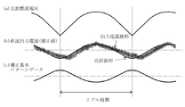
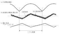
図3に示すように、補正基本パターンデータ(図3(c)参照)におけるリプル周期は、ダイオードブリッジ回路9により全波整流された電圧波形(図3(a)参照)の周期と同じである。
補正基本パターンデータは、出力リプル波形(直流出力電流波形の近似波形(図3(b)参照))の極性を上下反転させて、振幅の大きさが1になるように正規化したものであるため、直流出力電流波形の近似波形がcos関数の波形であれば、補正基本パターンデータもcos関数の波形となる。
The correction basic pattern data storage means 25 is a database in which correction basic pattern data for one or more ripple periods in DC output power is stored in advance.
As shown in FIG. 3, the ripple period in the corrected basic pattern data (see FIG. 3C) is the same as the period of the voltage waveform (see FIG. 3A) that has been full-wave rectified by the diode bridge circuit 9. .
The corrected basic pattern data is obtained by normalizing the amplitude of the output ripple waveform (approximate waveform of the DC output current waveform (see FIG. 3B)) by inverting the polarity up and down. Therefore, if the approximate waveform of the DC output current waveform is a cos function waveform, the correction basic pattern data also has a cos function waveform.
電力値算出手段26は、電流検出回路16および電圧検出回路17で検出された電流値および電圧値に基づいて、バッテリー19に供給される直流出力電力の現在の電力値を算出する。
The power value calculation means 26 calculates the current power value of the DC output power supplied to the
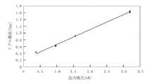
補正ゲイン算出手段27は、電力値算出手段26で予め求めていたリプル補正処理をしない場合の直流出力電力の電力値と、該直流出力電力におけるリプル電流値との相互関係を一次式で示した相互関係データ(図4参照)に基づいて、現在の電力値に対するリプル電流値を予測し、該予測したリプル電流値に基づいて補正ゲインを算出する。
なお、補正ゲイン算出手段27には、温度等の条件に応じて異なる複数の相互関係データが格納されている。
The correction gain calculation means 27 shows a linear relationship between the power value of the DC output power when the ripple correction processing previously obtained by the power value calculation means 26 is not performed and the ripple current value in the DC output power as a linear expression. A ripple current value for the current power value is predicted based on the correlation data (see FIG. 4), and a correction gain is calculated based on the predicted ripple current value.
Note that the correction gain calculation means 27 stores a plurality of pieces of correlation data that differ depending on conditions such as temperature.
補正量演算手段28は、同期検出回路15から同期信号が出力される度に、補正基本パターンデータ格納手段25に格納された補正基本パターンデータに、補正ゲイン算出手段27で算出された補正ゲインを乗算することで補正量を算出するとともに、該補正量を演算手段29に出力する。
The correction
演算手段29は、制御量算出部21で算出されたオン/オフ制御量に、補正量演算手段28で算出された補正量を加算する。
The calculating
PWM信号生成手段23は、上記補正量が加算されたオン/オフ制御量に基づいて、スイッチ手段5a〜5dのデューティ比を制御するためのPWM信号を生成する。
The PWM
[充電装置の動作]
次に、本実施形態に係る充電装置1の動作について具体的に説明する。
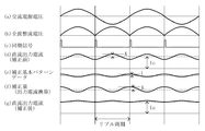
なお、本具体例では、リプル補正処理をしない状態で、出力回路7から出力される直流出力電流に大きさKのリプルが含まれている場合(図5(d)参照)について説明する。
[Operation of charging device]
Next, the operation of the
In this specific example, a case where a ripple of magnitude K is included in the DC output current output from the output circuit 7 without performing the ripple correction process (see FIG. 5D) will be described.
充電装置1では、交流電源2から供給された交流電源電圧(図5(a)参照)が、ダイオードブリッジ回路9により全波整流され(図5(b)参照)、かつ電解コンデンサ10により平滑されることで、直流入力電圧に変換されてDC/DCコンバータ回路4に供給される。
In the
DC/DCコンバータ回路4に供給された直流入力電圧は、インバータ回路5のスイッチ手段5a〜5dにより、交流電源2の周波数よりも高周波(数10kHz)の一次側交流電圧に変換された後に、昇圧回路6で昇圧されて二次側交流電圧として出力回路7に供給される。
The DC input voltage supplied to the DC /
出力回路7に供給された二次側交流電圧は、ダイオードブリッジ回路11により再び直流電圧に変換された後、LCローパスフィルタによりスイッチ手段5a〜5dで発生した数10kHzのスイッチングノイズが除去され、直流出力電圧としてバッテリー19に供給される。
The secondary side AC voltage supplied to the output circuit 7 is converted again to a DC voltage by the
ここで、直流出力電流におけるリプルの大きさは、補正ゲイン算出手段27により、電力値算出手段26で算出された現在の電力値と、図4に示す相互関係データとに基づいて算出(予測)される。例えば、図4から、現在の電力値が1.5kWの場合はリプル値が0.9(App)となることがわかる。
Here, the magnitude of the ripple in the DC output current is calculated (predicted) by the correction
補正ゲイン算出手段27により算出されたリプル値に基づいて、補正基本パターンデータ格納手段25に格納されている補正基本パターンデータ(図5(e)参照)の振幅をK倍とするための補正ゲインKが算出される。
一般には、補正ゲインはリプル値と比例関係にあるものであるが、ここでは簡単のために、補正ゲイン=リプル値として説明する。
Based on the ripple value calculated by the correction gain calculation means 27, the correction gain for making the amplitude of the correction basic pattern data (see FIG. 5E) stored in the correction basic pattern data storage means 25 K times. K is calculated.
In general, the correction gain has a proportional relationship with the ripple value, but here, for the sake of simplicity, the correction gain will be described as the ripple value.
補正ゲイン算出手段27により補正ゲインKが算出されると、補正量演算手段28により、同期検出回路15から出力される同期信号(図5(c)参照)に同期して、補正基本パターンデータに補正ゲインKを乗算した補正量(図5(f)参照)が刻々と算出され、該補正量が演算手段29に出力される。
When the correction gain K is calculated by the
補正基本パターンデータ格納手段25に格納されている補正基本パターンデータは、正規化された大きさ1のcos関数の波形であるため、補正量の大きさはKとなる(図5(f)参照)。
従って、例えば、現在の電力値が1.5kWの場合は補正量の大きさが0.9となる。
Since the correction basic pattern data stored in the correction basic pattern data storage means 25 is a normalized waveform of the cos function having a size of 1, the correction amount is K (see FIG. 5F). ).
Therefore, for example, when the current power value is 1.5 kW, the magnitude of the correction amount is 0.9.
演算手段29では、制御量算出部21で算出されたオン/オフ制御量に補正量演算手段28で算出された上記補正量が加算されて、その演算結果がPWM信号生成手段23に出力される。
In the calculating means 29, the correction amount calculated by the correction amount calculating means 28 is added to the on / off control amount calculated by the control
PWM信号生成手段23では、上記演算結果(補正量が加算されたオン/オフ制御量)に基づいてPWM信号が生成される。
これにより、スイッチ手段5a〜5dのデューティ比が変更され、直流出力電流のリプルが低減される(図5(g)参照)。
The PWM
Thereby, the duty ratio of the switch means 5a-5d is changed, and the ripple of DC output current is reduced (refer FIG.5 (g)).
結局、本実施形態に係る充電装置1によれば、リプル値分の補正量が加算されたスイッチ手段5a〜5dのオン/オフ制御量に基づいてスイッチ手段5a〜5dのデューティ比が制御されるので、リプルの低減を図るとともに、バッテリー19に安定した直流出力電力を供給することができる。
Eventually, according to the
また、本実施形態に係る充電装置1では、リプル値を増加させることなく、電解コンデンサ10の静電容量を小さくすることができる。このため、本実施形態に係る充電装置1によれば、装置全体の小型化および低コスト化を実現することができる。
Moreover, in the
以上、本発明に係る充電装置の好ましい実施形態について説明したが、本発明は上記実施形態に限定されるものではない。 As mentioned above, although preferable embodiment of the charging device which concerns on this invention was described, this invention is not limited to the said embodiment.
例えば、上記実施形態では、直流出力電流波形の近似波形をcos関数の波形とし、補正基本パターンデータもcos関数の波形としたが、図6に示すように、直流出力電流波形の近似波形を折れ線関数の波形とし、補正基本パターンデータも折れ線関数の波形とすることができる。
直流出力電流波形の近似波形および補正基本パターンデータを折れ線関数の波形とすることで、リプルをほぼ完全に解消することができる。
なお、補正基本パターンデータを折れ線関数の波形とした場合は、リプル1周期中に複数の関数(演算式)が存在することになるので、変曲点ごとに関数を切り替える必要がある。これに対して、補正基本パターンデータをcos関数の波形とした場合は、リプル1周期中に一つの関数しか存在しないので、いずれのタイミングであっても同じ関数を用いることができ、演算が容易になるという利点がある。
For example, in the above embodiment, the approximate waveform of the DC output current waveform is the waveform of the cos function, and the correction basic pattern data is also the waveform of the cos function. However, as shown in FIG. The waveform of a function can be used, and the correction basic pattern data can also be a waveform of a broken line function.
By making the approximate waveform of the DC output current waveform and the corrected basic pattern data into a waveform of a polygonal line function, ripples can be almost completely eliminated.
When the correction basic pattern data is a polygonal line function waveform, there are a plurality of functions (calculation formulas) in one ripple period, and therefore, it is necessary to switch the function for each inflection point. On the other hand, when the correction basic pattern data is a waveform of the cos function, there is only one function in one ripple period, so the same function can be used at any timing and calculation is easy. There is an advantage of becoming.
また、cos関数や折れ線関数の補正基本パターンデータを補正基本パターンデータ格納手段25に格納する替わりに、フィードバック制御周期毎に算出したcos関数や折れ線関数の計算結果がテーブル化されたものを補正基本パターンデータとして補正基本パターンデータ格納手段25に格納してもよい。 Further, instead of storing the correction basic pattern data of the cos function or the polygonal line function in the correction basic pattern data storage means 25, a table in which the calculation results of the cos function and the polygonal line function calculated for each feedback control period are tabulated is corrected. The pattern data may be stored in the corrected basic pattern data storage means 25.
さらに、上記実施形態では、補正基本パターンデータが直流出力電流波形の近似波形の極性を上下反転させたものであるため、演算手段29では、オン/オフ制御量に補正量を加算しているが、補正基本パターンデータが上記極性を上下反転させたものでない場合(極性が同じ場合)は、演算手段29では、オン/オフ制御量から補正量を減算する必要がある。 Furthermore, in the above embodiment, the correction basic pattern data is obtained by inverting the polarity of the approximate waveform of the DC output current waveform, so the calculation means 29 adds the correction amount to the on / off control amount. When the basic correction pattern data is not the above-mentioned polarity inverted (when the polarities are the same), the calculation means 29 needs to subtract the correction amount from the on / off control amount.
また、上記実施形態では、補正ゲインK=リプル値とし、該補正ゲインKを補正基本パターンデータに乗算して補正量を算出しているが、補正ゲインK=リプル値とするとリプルを完全に解消することができない場合は、電力値算出手段26で算出された現在の出力電力値におけるリプル電流値が最小となるような定数K’(=リプル値×比例定数)を補正ゲインとして用いてもよい。
リプル値に乗算される比例定数は、例えば、補正ゲインK=リプル値として算出した補正量と、現在の出力電力値におけるリプル電流値との差に基づいて算出することができる。
定数K’(=リプル値×比例定数)を補正ゲインとして用いる場合、電力値算出手段26で予め求めていた直流出力電力の電力値と該直流出力電力における定数K’との相互関係を一次式で示した相互関係データを補正ゲイン算出手段27に格納しておき、上記相互関係データから現在の出力電力値に対応した定数K’を補正ゲインとして算出することが好ましい。
In the above embodiment, the correction gain K is set to the ripple value, and the correction gain K is multiplied by the correction basic pattern data to calculate the correction amount. However, when the correction gain K is set to the ripple value, the ripple is completely eliminated. If this is not possible, a constant K ′ (= ripple value × proportional constant) that minimizes the ripple current value at the current output power value calculated by the power value calculating means 26 may be used as the correction gain. .
The proportionality constant multiplied by the ripple value can be calculated based on, for example, the difference between the correction amount calculated as the correction gain K = ripple value and the ripple current value at the current output power value.
When the constant K ′ (= ripple value × proportional constant) is used as the correction gain, the linear relationship between the power value of the DC output power obtained in advance by the power value calculation means 26 and the constant K ′ in the DC output power is a linear expression. Is stored in the correction gain calculating means 27, and a constant K ′ corresponding to the current output power value is calculated as a correction gain from the correlation data.
なお、本発明は、電気自動車に搭載される車載型の充電装置だけでなく、他の分野の充電装置にも適用することができる。 Note that the present invention can be applied not only to a vehicle-mounted charging device mounted on an electric vehicle, but also to charging devices in other fields.
1 充電装置
2 交流電源
3 整流平滑回路
4 DC/DCコンバータ回路
5 インバータ回路
5a〜5d スイッチ手段
6 昇圧回路
7 出力回路
8 スイッチ制御回路
9 ダイオードブリッジ回路
10 電解コンデンサ
11 ダイオードブリッジ回路
12 コイル
13 平滑コンデンサ
14 シャント抵抗
15 同期検出回路
16 電流検出回路
17 電圧検出回路
18 目標電力値設定回路
19 バッテリー
20 目標電流値演算手段
21 制御量算出部
22 補正量算出部
23 PWM信号生成手段
24a、24b AD変換手段
25 補正基本パターンデータ格納手段
26 電力値算出手段
27 補正ゲイン算出手段
28 補正量演算手段
29 演算手段
DESCRIPTION OF
Claims (7)
前記交流電力の極性が反転するタイミングで同期信号を出力する同期検出回路をさらに備え、
前記スイッチ制御回路は、
前記フィードバック制御により前記スイッチ手段のオン/オフ制御量を算出する制御量算出部と、
前記同期信号に同期するとともに、前記バッテリーに出力される出力リプル波形を反転させ、かつ振幅の大きさを1に正規化した補正基本パターンに基づいて補正量を算出する補正量算出部と、
を有し、
前記制御量算出部で算出されたオン/オフ制御量に前記補正量算出部で算出された補正量を加算して前記デューティ比を求めるリプル補正処理を行い、
前記補正量算出部は、
前記バッテリーへの出力電力値を算出する電力値算出手段と、
予め求めていた前記リプル補正処理をしない場合の前記バッテリーへの出力電力値とリプル値との相互関係を示す相互関係データに基づいて前記電力値算出手段で算出された出力電力値における補正ゲインを算出する補正ゲイン算出手段と、
を有し、
前記補正基本パターンに前記補正ゲインを乗算することにより、前記補正量を算出することを特徴とする充電装置。 A rectifying / smoothing circuit that rectifies and smoothes AC power supplied from an AC power source to generate DC input power, and DC / DC that switches the DC input power by a switching means to convert it to DC output power and outputs the DC power to a battery. A charging device comprising: a converter circuit; and a switch control circuit that feedback-controls the duty ratio of the switch means so that an output power value to the battery becomes a preset set power value,
A synchronization detection circuit that outputs a synchronization signal at a timing at which the polarity of the AC power is inverted;
The switch control circuit includes:
A control amount calculation unit for calculating an on / off control amount of the switch means by the feedback control;
A correction amount calculation unit that calculates a correction amount based on a correction basic pattern that is synchronized with the synchronization signal, inverts an output ripple waveform that is output to the battery , and that is normalized to a magnitude of 1 ;
Have
There line ripple correction processing for obtaining the duty ratio by adding the correction amount calculated in the correction amount calculation unit on / off control amount calculated by the control amount calculating section,
The correction amount calculation unit
Power value calculating means for calculating an output power value to the battery;
The correction gain in the output power value calculated by the power value calculation means based on the correlation data indicating the correlation between the output power value to the battery and the ripple value when the ripple correction processing that has been obtained in advance is not performed. Correction gain calculating means for calculating;
Have
The charging device , wherein the correction amount is calculated by multiplying the correction basic pattern by the correction gain .
少なくとも前記直流出力電力におけるリプル周期の1周期分の波形データからなる前記補正基本パターンデータを格納する補正基本パターンデータ格納手段をさらに有し、Correction basic pattern data storage means for storing the correction basic pattern data consisting of waveform data of at least one ripple period in the DC output power;
前記補正基本パターンデータ格納手段に格納された前記補正基本パターンに前記補正ゲインを乗算することにより、前記補正量を算出することを特徴とする請求項1に記載の充電装置。The charging device according to claim 1, wherein the correction amount is calculated by multiplying the correction basic pattern stored in the correction basic pattern data storage unit by the correction gain.
前記補正ゲイン算出手段は、前記電力値算出手段で算出された出力電力値における前記定数を前記相互関係データから読み込むことで、該定数を前記補正ゲインとして算出することを特徴とする請求項1ないし3のいずれかに記載の充電装置。The correction gain calculation means reads the constant in the output power value calculated by the power value calculation means from the correlation data, thereby calculating the constant as the correction gain. 4. The charging device according to any one of 3.
前記電力値算出手段は、前記電圧検出回路および前記電流検出回路で検出された電圧値および電流値に基づいて前記バッテリーへの出力電力値を算出することを特徴とする請求項1ないし4のいずれかに記載の充電装置。5. The power value calculating means calculates an output power value to the battery based on a voltage value and a current value detected by the voltage detection circuit and the current detection circuit. A charging device according to claim 1.
Priority Applications (1)
| Application Number | Priority Date | Filing Date | Title |
|---|---|---|---|
| JP2011233821A JP5773435B2 (en) | 2011-10-25 | 2011-10-25 | Charger |
Applications Claiming Priority (1)
| Application Number | Priority Date | Filing Date | Title |
|---|---|---|---|
| JP2011233821A JP5773435B2 (en) | 2011-10-25 | 2011-10-25 | Charger |
Publications (2)
| Publication Number | Publication Date |
|---|---|
| JP2013093952A JP2013093952A (en) | 2013-05-16 |
| JP5773435B2 true JP5773435B2 (en) | 2015-09-02 |
Family
ID=48616644
Family Applications (1)
| Application Number | Title | Priority Date | Filing Date |
|---|---|---|---|
| JP2011233821A Expired - Fee Related JP5773435B2 (en) | 2011-10-25 | 2011-10-25 | Charger |
Country Status (1)
| Country | Link |
|---|---|
| JP (1) | JP5773435B2 (en) |
Families Citing this family (3)
| Publication number | Priority date | Publication date | Assignee | Title |
|---|---|---|---|---|
| JP6026049B2 (en) | 2014-11-11 | 2016-11-16 | 三菱電機株式会社 | Power converter |
| ES2746231T3 (en) | 2016-02-05 | 2020-03-05 | Guangdong Oppo Mobile Telecommunications Corp Ltd | Charge control method and adapter |
| CN117656893B (en) * | 2022-08-30 | 2025-03-11 | 比亚迪股份有限公司 | Charger control method, device, charger and vehicle |
Family Cites Families (3)
| Publication number | Priority date | Publication date | Assignee | Title |
|---|---|---|---|---|
| JPH05292741A (en) * | 1992-04-09 | 1993-11-05 | Kageki Matsui | Forward converter for improving higher harmonic characteristics of power supply |
| EP0757429B1 (en) * | 1995-07-31 | 1998-11-18 | Hewlett-Packard Company | Switched mode power supply with power factor correction |
| JP2732428B2 (en) * | 1995-09-08 | 1998-03-30 | 西芝電機株式会社 | Chopper device |
-
2011
- 2011-10-25 JP JP2011233821A patent/JP5773435B2/en not_active Expired - Fee Related
Also Published As
| Publication number | Publication date |
|---|---|
| JP2013093952A (en) | 2013-05-16 |
Similar Documents
| Publication | Publication Date | Title |
|---|---|---|
| JP5822304B2 (en) | Charger | |
| US9231469B2 (en) | Auto-tuning current loop compensation for power factor correction controller | |
| JP6075462B2 (en) | Power factor correction circuit | |
| JP6158739B2 (en) | Power converter | |
| US10312800B2 (en) | AC-DC converter | |
| JP2013074667A (en) | Switching power supply, and ac waveform generating method in switching power supply | |
| JP2010088150A (en) | Charger | |
| JP2012217247A (en) | Power-supply circuit | |
| CN112544033B (en) | AC Inverter with Active Neutral Balancing | |
| US10374513B2 (en) | AC-DC converter | |
| JP5780597B2 (en) | Charger | |
| JP5773435B2 (en) | Charger | |
| JP2015228715A (en) | Control device, DC-DC converter, switching power supply device, and information processing device | |
| JP5617748B2 (en) | Charger | |
| JP2018137841A (en) | Power factor improvement circuit and charger | |
| JP6250181B2 (en) | Power factor compensation circuit for power supply control device, control method therefor, and LED lighting device | |
| JP5507417B2 (en) | Power supply | |
| KR20150101913A (en) | Method for battery charging control and apparatus therefor | |
| JP6347756B2 (en) | Power supply | |
| JP5456578B2 (en) | Power converter | |
| JP2013247836A (en) | Power conversion device | |
| JP2014187742A (en) | Inverter device | |
| JP6226785B2 (en) | Power supply device, power supply device control method, and control program | |
| JP2004015897A (en) | PWM rectifier output control method and output control device | |
| JP6943209B2 (en) | Power factor improving device |
Legal Events
| Date | Code | Title | Description |
|---|---|---|---|
| A621 | Written request for application examination |
Free format text: JAPANESE INTERMEDIATE CODE: A621 Effective date: 20140409 |
|
| A977 | Report on retrieval |
Free format text: JAPANESE INTERMEDIATE CODE: A971007 Effective date: 20150204 |
|
| A131 | Notification of reasons for refusal |
Free format text: JAPANESE INTERMEDIATE CODE: A131 Effective date: 20150210 |
|
| A521 | Request for written amendment filed |
Free format text: JAPANESE INTERMEDIATE CODE: A523 Effective date: 20150312 |
|
| TRDD | Decision of grant or rejection written | ||
| A01 | Written decision to grant a patent or to grant a registration (utility model) |
Free format text: JAPANESE INTERMEDIATE CODE: A01 Effective date: 20150624 |
|
| A61 | First payment of annual fees (during grant procedure) |
Free format text: JAPANESE INTERMEDIATE CODE: A61 Effective date: 20150625 |
|
| R150 | Certificate of patent or registration of utility model |
Ref document number: 5773435 Country of ref document: JP Free format text: JAPANESE INTERMEDIATE CODE: R150 |
|
| R250 | Receipt of annual fees |
Free format text: JAPANESE INTERMEDIATE CODE: R250 |
|
| R250 | Receipt of annual fees |
Free format text: JAPANESE INTERMEDIATE CODE: R250 |
|
| R250 | Receipt of annual fees |
Free format text: JAPANESE INTERMEDIATE CODE: R250 |
|
| R250 | Receipt of annual fees |
Free format text: JAPANESE INTERMEDIATE CODE: R250 |
|
| R250 | Receipt of annual fees |
Free format text: JAPANESE INTERMEDIATE CODE: R250 |
|
| R250 | Receipt of annual fees |
Free format text: JAPANESE INTERMEDIATE CODE: R250 |
|
| LAPS | Cancellation because of no payment of annual fees |