JP5772771B2 - Eddy current reducer - Google Patents
Eddy current reducer Download PDFInfo
- Publication number
- JP5772771B2 JP5772771B2 JP2012196771A JP2012196771A JP5772771B2 JP 5772771 B2 JP5772771 B2 JP 5772771B2 JP 2012196771 A JP2012196771 A JP 2012196771A JP 2012196771 A JP2012196771 A JP 2012196771A JP 5772771 B2 JP5772771 B2 JP 5772771B2
- Authority
- JP
- Japan
- Prior art keywords
- braking
- time
- actuator
- disk
- brake
- Prior art date
- Legal status (The legal status is an assumption and is not a legal conclusion. Google has not performed a legal analysis and makes no representation as to the accuracy of the status listed.)
- Active
Links
Images


Description
本発明は、トラックやバスなどの車両に補助ブレーキとして搭載される渦電流式減速装置に関し、特に、制動トルクを発生させるために永久磁石を用いた渦電流式減速装置に関する。 The present invention relates to an eddy current type reduction gear mounted as an auxiliary brake on a vehicle such as a truck or a bus, and more particularly, to an eddy current type reduction gear using a permanent magnet to generate a braking torque.
永久磁石(以下、単に「磁石」ともいう)を用いた渦電流式減速装置(以下、単に「減速装置」ともいう)は、プロペラシャフトなどの回転軸に固定した制動部材を有し、制動時に、磁石からの磁界の作用で、磁石と対向する制動部材の表面に渦電流を発生させ、これにより、回転軸と一体で回転する制動部材に回転方向と逆向きの制動力(制動トルク)が生じ、回転軸を減速させるものである。減速装置は、制動力をもたらすために渦電流が発生させられる制動部材、および磁石を保持して制動部材と対をなす磁石保持部材の形状に応じてドラム型とディスク型に大別され、制動と非制動とを切り替える構造も様々ある。 An eddy current type speed reducer (hereinafter also simply referred to as “speed reducer”) using a permanent magnet (hereinafter also simply referred to as “magnet”) has a braking member fixed to a rotating shaft such as a propeller shaft, and is used during braking. An eddy current is generated on the surface of the braking member facing the magnet by the action of the magnetic field from the magnet, so that a braking force (braking torque) in the direction opposite to the rotation direction is applied to the braking member that rotates integrally with the rotating shaft. Is generated, and the rotational axis is decelerated. The speed reducer is roughly divided into a drum type and a disk type according to the shape of a braking member that generates eddy current to provide a braking force, and a magnet holding member that holds the magnet and forms a pair with the braking member. There are also various structures for switching between non-braking and non-braking.
従来慣用されている減速装置では、例えばドラム型の場合、車両の回転軸に制動部材として円筒状の制動ドラムが固定され、この制動ドラムの内側に、磁石保持部材として、制動ドラムの内周面に対向して円周方向にわたり複数の永久磁石を保持した磁石保持ドラムが配設されており、磁石保持ドラムに接続されたアクチュエータの作動により、磁石保持ドラムの位置、すなわち磁石の位置を制動と非制動それぞれの位置に切り替えるようになっている。 In a conventionally used speed reducer, for example, in the case of a drum type, a cylindrical brake drum is fixed as a brake member to a rotating shaft of a vehicle, and an inner peripheral surface of the brake drum as a magnet holding member inside the brake drum. A magnet holding drum that holds a plurality of permanent magnets in the circumferential direction is disposed opposite to the actuator, and the position of the magnet holding drum, that is, the position of the magnet is braked by the operation of an actuator connected to the magnet holding drum. Switching to each non-braking position.
また、近年では、装置の小型化への要請に対応するため、磁石を保持する磁石保持部材を回転軸に回転可能に支持し、制動時にその磁石保持部材を摩擦ブレーキによって静止させる減速装置が提案されている(例えば、特許文献1〜5参照)。この減速装置は、以下に示すように、非制動時に磁石保持部材と制動部材が同期して一体的に回転することから、同期回転方式の減速装置と称される。
In recent years, in order to respond to the demand for downsizing of the device, a reduction gear device has been proposed in which a magnet holding member holding a magnet is rotatably supported on a rotating shaft and the magnet holding member is stopped by a friction brake during braking. (For example, see
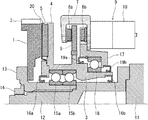
図1は、従来の同期回転方式の減速装置の構成例を示す縦断面図である。同図に示す減速装置はディスク型であり、制動部材としての制動ディスク1と、磁石保持部材としてその制動ディスク1の主面に対向し永久磁石5を保持する磁石保持ディスク4とを備える。
FIG. 1 is a longitudinal sectional view showing a configuration example of a conventional synchronous rotation speed reduction device. The speed reduction device shown in the figure is of a disk type, and includes a
図1では、制動ディスク1は、プロペラシャフトなどの回転軸11と一体で回転するように構成される。具体的には、回転軸11と同軸上に連結軸12がボルトなどによって固定され、フランジ付きのスリーブ13がその連結軸12にスプラインで噛み合いながら挿入されてナット14で固定されている。制動ディスク1は、回転軸11と一体化されたスリーブ13のフランジにボルトなどで固定され、これにより回転軸11と一体で回転するようになる。
In FIG. 1, the
制動ディスク1には、例えばその外周に放熱フィン2が設けられる。この放熱フィン2は、制動ディスク1と一体成形され、制動ディスク1そのものを冷却する役割を担う。制動ディスク1の材質は、鉄などの強磁性材料や、フェライト系ステンレス鋼などの弱磁性材料である。
The
図1では、磁石保持ディスク4は、回転軸11に対し回転可能に構成される。磁石保持ディスク4は、連結軸12と同心状の環状部材3と一体成形されたり、個別に成形されてボルトなどで環状部材3に固定されたりしたものである。環状部材3は回転軸11と一体化されたスリーブ13に軸受15a、15bを介して支持され、これにより磁石保持ディスク4は回転軸11に対し自由に回転が可能になる。軸受15a、15bには潤滑グリスが充填され、この潤滑グリスは、環状部材3の前後両端に装着されたリング状のシール部材16a、16bにより漏出を防止される。
In FIG. 1, the magnet holding disk 4 is configured to be rotatable with respect to the rotating
磁石保持ディスク4には、制動ディスク1の主面と対向する面に、円周方向にわたり複数の永久磁石5が固着される。永久磁石5は、磁極(N極、S極)の向きが磁石保持ディスク4の軸方向であり、円周方向に隣接するもの同士で磁極が交互に異なるように配置される。これにより、永久磁石5から制動ディスク1の主面に作用する磁界の向きは、円周方向にわたり交互に異なるようになる。
A plurality of
図1では、磁石保持ディスク4には、永久磁石5の全体を覆うように、薄板からなる磁石カバー20が取り付けられる。この磁石カバー20は、鉄粉や粉塵から永久磁石5を保護するのみならず、永久磁石5の保有する磁力が熱影響で低下するのを防止するために、制動ディスク1からの輻射熱を遮る役割を担う。磁石カバー20の材質は、永久磁石5からの磁界に影響を及ぼさないように、非磁性材料である。
In FIG. 1, a
図1に示す減速装置は、制動時に磁石保持ディスク4を静止させる摩擦ブレーキとしてディスクブレーキを備える。このディスクブレーキは、磁石保持ディスク4の後方で環状部材3と一体のブレーキディスク6と、このブレーキディスク6を間に挟む摩擦部材としてブレーキパッド8a、8bを有するブレーキキャリパ7と、このブレーキキャリパ7を駆動させる電動式直動アクチュエータ9とから構成される。ブレーキディスク6は、ボルトなどで環状部材3に取り付けられ、環状部材3と一体化される。
The speed reducer shown in FIG. 1 includes a disk brake as a friction brake that stops the magnet holding disk 4 during braking. This disc brake includes a brake disc 6 integral with the annular member 3 behind the magnet holding disc 4, a
ブレーキキャリパ7は、前後で一対のブレーキパッド8a、8bを有しており、ブレーキパッド8a、8bの間にブレーキディスク6を配置し所定の隙間を設けて挟んだ状態で、バネを搭載したボルトなどによりブラケット17に付勢支持される。このブラケット17は、車両のシャーシやクロスメンバーなどの非回転部に取り付けられる。また、ブラケット17は、ブレーキディスク6の後方で環状部材3を包囲し、環状部材3に軸受18を介して回転可能に支持される。この軸受18にも潤滑グリスが充填され、この潤滑グリスは、ブラケット17の前後両端に装着されたリング状のシール部材19a、19bにより漏出を防止される。
The
ブレーキキャリパ7には、アクチュエータ9がボルトなどで固定される。アクチュエータ9は、電動モータ10によって駆動し、電動モータ10の回転運動を直線運動に変換して後側のブレーキパッド8bをブレーキディスク6に向け直線移動させる。これにより、後側のブレーキパッド8bがブレーキディスク6を押圧し、これに伴う反力の作用で、前側のブレーキパッド8aがブレーキディスク6に向け移動し、その結果、ブレーキディスク6を前後のブレーキパッド8a、8bで強力に挟み込む。
An
図1に示す減速装置において、非制動時は、ディスクブレーキ(摩擦ブレーキ)を作動させない状態にある。このとき、回転軸11と一体で制動ディスク1が回転するのに伴い、環状部材3と一体の磁石保持ディスク4が、永久磁石5と制動ディスク1との磁気吸引作用により、制動ディスク1と同期して一体的に回転する。このため、制動ディスク1と永久磁石5との間に相対的な回転速度差が生じないことから、制動力は発生しない。
In the speed reducer shown in FIG. 1, the disc brake (friction brake) is not operated during non-braking. At this time, as the
一方、制動時は、ディスクブレーキ(摩擦ブレーキ)を作動させ、ブレーキディスク6がブレーキパッド8a、8bによって挟み込まれ、これにより環状部材3と一体の磁石保持ディスク4の回転が停止し、磁石保持ディスク4が静止する。制動ディスク1が回転している際に磁石保持ディスク4のみが静止すると、制動ディスク1と永久磁石5との間に相対的な回転速度差が生じるため、永久磁石5からの磁界の作用で、制動ディスク1の主面に渦電流が発生し、制動ディスク1を介して回転軸11に制動力を発生させることができる。
On the other hand, at the time of braking, the disc brake (friction brake) is operated and the brake disc 6 is sandwiched between the
このように図1に示す同期回転方式の減速装置はディスク型であるが、ドラム型であっても成り立つ。 As described above, the synchronous rotation type speed reduction device shown in FIG. 1 is a disc type, but a drum type is also possible.
ところで、減速装置を使用する際、走行状況に応じて制動トルクを調整できると好都合である。例えば、空荷で走行しているときや、滑り易い路面を走行しているときは、車輪の不用意なロックを防止するため、運転手の操作により弱い制動トルクを指定し、所望した指定の弱い制動トルクを発生できるとよい。これとは逆に、満載状態で走行しているときには、十分な減速を行うため、強い制動トルクを指定し、所望した指定の強い制動トルクを発生できるとよい。また、車両の主ブレーキを主体とするブレーキ統合システムに減速装置が組み込まれている場合は、運転手の操作によることなく、ブレーキ統合システムの制御装置が最適な制動トルクを演算して指定し、所望した指定の最適な制動トルクを発生できるとよい。 By the way, when using the speed reducer, it is advantageous if the braking torque can be adjusted in accordance with the traveling situation. For example, when driving on an empty load or on a slippery road surface, in order to prevent inadvertent locking of the wheels, a weak braking torque is specified by the driver's operation, and the desired specified It should be able to generate a weak braking torque. On the contrary, when the vehicle is traveling in the full load state, it is preferable to specify a strong braking torque and generate a desired strong braking torque in order to perform sufficient deceleration. In addition, when the speed reducer is incorporated in the brake integrated system mainly composed of the main brake of the vehicle, the controller of the brake integrated system calculates and specifies the optimum braking torque without depending on the driver's operation, It is preferable that an optimum braking torque of a desired designation can be generated.
この点、上記の従来慣用されている減速装置では、例えば特許文献6に記載されるように、制動時に磁石の位置をアクチュエータで変化させることにより、制動トルクを調整できるので、所望の制動トルクを適宜指定して発生させることが可能である。 In this regard, in the above-described conventionally used reduction gears, for example, as described in Patent Document 6, the braking torque can be adjusted by changing the position of the magnet with an actuator during braking. It is possible to generate by designating as appropriate.
しかし、上記した従来の同期回転方式の減速装置では事情が異なり、制動時に磁石保持部材を静止させ、それを継続して維持するのみであるため、制動トルクを指定することはそもそもできず、所望する制動トルクがあってもこれを意図的に発生させることは不可能である。 However, the situation is different in the conventional synchronous rotation type speed reducer described above, and it is only possible to keep the magnet holding member stationary at the time of braking and to maintain it continuously. Therefore, it is impossible to specify the braking torque in the first place. Even if there is a braking torque to be generated, it is impossible to generate this intentionally.
本発明は、上記の実情に鑑みてなされたものであり、制動時に所望する指定の制動トルクを発生させることが可能な同期回転方式の渦電流式減速装置を提供することを目的とする。 The present invention has been made in view of the above circumstances, and an object of the present invention is to provide a synchronous rotation type eddy current reduction device capable of generating a desired braking torque desired during braking.
本発明者らは、上記目的を達成するために鋭意検討を重ねた。その結果、永久磁石を用いた同期回転方式の減速装置において、制動時に、厳密には、摩擦ブレーキのアクチュエータの作動ONに伴って100%の制動トルクが発生するのにタイムラグが生じること、およびアクチュエータの作動OFFに伴って制動トルクが消失するのにタイムラグが生じることに着目し、所望する指定の制動トルクでの制動を可能にするには、そのようなタイムラグの時間よりも短い時間間隔でアクチュエータの作動ON/OFFを繰り返すのが有効であることを知見し、本発明を完成させた。 The inventors of the present invention have made extensive studies in order to achieve the above object. As a result, in a synchronous rotation type speed reduction device using a permanent magnet, at the time of braking, strictly speaking, a time lag occurs when 100% braking torque is generated when the actuator of the friction brake is turned on, and the actuator Focusing on the fact that a time lag occurs when the braking torque disappears when the operation of the actuator is turned off, and in order to enable the braking with the desired designated braking torque, the actuator is operated at a time interval shorter than the time lag time. It has been found that it is effective to repeat ON / OFF of the above, and the present invention has been completed.
本発明の渦電流式減速装置は、
車両の回転軸に固定された制動部材と、
この制動部材に円周方向にわたり交互に向きの異なる磁界を作用させる複数の永久磁石を保持し、回転軸に回転可能に支持された磁石保持部材と、
制動時に磁石保持部材に摩擦部材を押し付けるアクチュエータを有する摩擦ブレーキと、を備えた渦電流式減速装置であって、
制動部材の回転速度を検出する回転速度検出器と、
アクチュエータの動作を制御する制御装置と、を備えており、
制御装置は、
(ステップ1)指定の制動トルクによる制動の指令が与えられると、回転速度検出器より制動部材の実回転速度を取得すること、
(ステップ2)制動トルクおよび制動部材の回転速度ごとに予め定められたデータテーブルから、ステップ1で取得した指定の制動トルクおよび制動部材の実回転速度に対応して、アクチュエータの1回目の作動ON時間、2回目以降の作動ON時間および作動OFF時間を選定すること、
(ステップ3)ステップ2で選定したアクチュエータの1回目の作動ON時間、2回目以降の作動ON時間および作動OFF時間でアクチュエータの作動ON/OFFを繰り返すこと、の一連の各ステップを実行すること、
を特徴とする。
The eddy current type speed reducer of the present invention is
A braking member fixed to the rotating shaft of the vehicle;
A magnet holding member that holds a plurality of permanent magnets that alternately apply different magnetic fields to the braking member in the circumferential direction, and is rotatably supported on a rotating shaft;
An eddy current reduction device comprising: a friction brake having an actuator that presses the friction member against the magnet holding member during braking;
A rotational speed detector for detecting the rotational speed of the braking member;
A control device for controlling the operation of the actuator,
The control device
(Step 1) When a command for braking by a designated braking torque is given, acquiring the actual rotational speed of the braking member from the rotational speed detector;
(Step 2) The actuator is turned on for the first time according to the specified braking torque and the actual rotational speed of the braking member acquired in
(Step 3) Executing a series of steps of repeating the operation ON / OFF of the actuator at the first operation ON time, the second operation ON time and the operation OFF time of the actuator selected in
It is characterized by.
本発明の渦電流式減速装置によれば、アクチュエータの作動ON/OFFを繰り返す制御の制動動作を実行して、アクチュエータによる摩擦部材の押付け/解除を繰り返し、これに伴って磁石保持ディスクの回転速度を制御することにより、発生する制動トルクをほぼ一定に調整でき、その結果として、指定の制動トルクTを発生させることができる。 According to the eddy current type speed reducer of the present invention, the braking operation of the control for repeatedly turning the actuator on / off is executed, and the pressing / releasing of the friction member by the actuator is repeated, and the rotational speed of the magnet holding disk is accordingly accompanied. By controlling this, the generated braking torque can be adjusted to be substantially constant, and as a result, the designated braking torque T can be generated.
以下に、本発明の同期回転方式の渦電流式減速装置の実施形態について詳述する。
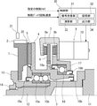
図2は、本発明の同期回転方式の減速装置の構成例を示す模式図である。同図に示す本発明の減速装置はディスク型に相当するものであり、前記図1に示す減速装置の構成を基本とし、重複する説明は適宜省略する。
Hereinafter, embodiments of the synchronous rotation type eddy current type speed reducer of the present invention will be described in detail.
FIG. 2 is a schematic diagram showing a configuration example of the synchronous rotation type reduction gear of the present invention. The speed reducer of the present invention shown in the figure is equivalent to a disk type, and is based on the configuration of the speed reducer shown in FIG.
図2に示すように、本発明の減速装置は、制動部材として制動ディスク1と、磁石保持部材として磁石保持ディスク4とを備える。制動ディスク1は、回転軸11に固定されて回転軸11と一体で回転する。磁石保持ディスク4は、制動ディスク1の主面に円周方向にわたり交互に向きの異なる磁界を作用させる複数の永久磁石5を保持する。磁石保持ディスク4は、環状部材3と一体化されたものであり、この環状部材3を介して回転軸11に回転可能に支持されている。また、環状部材3にはブレーキディスク6が取り付けられており、これらの磁石保持ディスク4、環状部材3およびブレーキディスク6は一体化されている。
As shown in FIG. 2, the speed reducer of the present invention includes a
制動時、摩擦ブレーキ(ディスクブレーキ)のアクチュエータ9の作動ONにより、摩擦部材としてのブレーキパッド8a、8bがブレーキディスク6に押し付けられ、その押付けによる摩擦抵抗により、ブレーキディスク6および環状部材3と一体の磁石保持ディスク4の回転が抑えられる。磁石保持ディスク4が制動ディスク1と同期して回転している際に磁石保持ディスク4の回転が抑えられると、制動ディスク1と永久磁石5との間に相対的な回転速度差が生じるため、永久磁石5からの磁界の作用で、制動ディスク1の主面に渦電流が発生し、これに伴って回転軸11と一体の制動ディスク1に制動トルクが発生する。
During braking, when the
そして、アクチュエータ9の作動OFFにより、ブレーキパッド8a、8b(摩擦部材)の押付けが解除されると、磁石保持ディスク4は何ら拘束されないことから、永久磁石5と制動ディスク1との磁気吸引作用により、制動ディスク1と同期して一体的に回転するようになる。これに伴って、制動トルクが消失し非制動状態となる。
When the pressing of the
ここで、同期回転方式の減速装置における制動トルクの挙動に関し、厳密には、アクチュエータ9の作動ONに伴って瞬時に100%の制動トルクが発生するわけではなく、アクチュエータ作動のON時点から100%の制動トルクの発生までにタイムラグが生じる。さらに、アクチュエータ9の作動OFFに伴って瞬時に制動トルクが消失するわけではなく、アクチュエータ作動のOFF時点から制動トルクの消失までにタイムラグが生じる。その状況を以下に説明する。
Here, regarding the behavior of the braking torque in the synchronous rotation type reduction gear, strictly speaking, 100% braking torque is not instantly generated when the
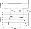
図3は、従来の同期回転方式の減速装置における制動トルクの挙動の一例を示すタイムチャートである。同図に示すように、制動に際し、アクチュエータの作動ONにより、摩擦部材がブレーキディスクに押し付けられ、これに伴って磁石保持ディスクの回転速度が急激に減少するとともに、制動トルクが発生し急激に上昇する。磁石保持ディスクの回転速度が0となり、磁石保持ディスクが静止すると、制動トルクは100%に達する。 FIG. 3 is a time chart showing an example of the behavior of the braking torque in the conventional synchronous rotation type reduction gear. As shown in the figure, when braking, the friction member is pressed against the brake disk by turning on the actuator, and as a result, the rotational speed of the magnet holding disk rapidly decreases and braking torque is generated and rapidly increased. To do. When the rotation speed of the magnet holding disk becomes zero and the magnet holding disk is stationary, the braking torque reaches 100%.
こうして、アクチュエータの作動ONの時点から100%の制動トルクの発生までには、タイムラグが生じることになる。このようなアクチュエータの作動ONの時点から100%の制動トルクの発生までのタイムラグは、制動に際しての制動ディスクの回転速度、すなわち磁石保持ディスクの回転速度によって多少異なるが、0.1〜0.3[s(秒)]程度である。 Thus, there is a time lag from when the actuator is turned on until 100% braking torque is generated. The time lag from the time when the actuator is activated to the time when 100% braking torque is generated varies slightly depending on the rotational speed of the braking disk during braking, that is, the rotational speed of the magnet holding disk, but is 0.1 to 0.3. It is about [s (second)].
従来の減速装置では、アクチュエータの作動ONの状態がそのまま維持され、制動ディスクに100%の制動トルクが継続して作用する。これにより、制動ディスクの回転速度が次第に減少し、これに伴って制動トルクが徐々に降下する。 In the conventional speed reducer, the actuator ON state is maintained as it is, and 100% braking torque continues to act on the braking disk. As a result, the rotational speed of the braking disk gradually decreases, and the braking torque gradually decreases accordingly.
このような制動状態から非制動への切り替えに際しては、アクチュエータの作動OFFにより、摩擦部材の押付けが解除され、これに伴って永久磁石と制動ディスクとの磁気吸引作用により、磁石保持ディスクが回転し始める。そして、磁石保持ディスクの回転速度の増加に伴って制動トルクが徐々に降下し、さらにある時点から急激に降下し、終に磁石保持ディスクの回転速度が制動ディスクの回転速度と同じになると、制動トルクが0になり消失する。 When switching from such a braking state to non-braking, the pressing of the friction member is released by turning off the actuator, and accordingly, the magnet holding disk rotates due to the magnetic attraction between the permanent magnet and the braking disk. start. As the rotation speed of the magnet holding disk increases, the braking torque gradually decreases, and then suddenly decreases from a certain point. Finally, when the rotation speed of the magnet holding disk becomes the same as the rotation speed of the braking disk, Torque becomes zero and disappears.
こうして、アクチュエータの作動OFFの時点から制動トルクの急激な減少開始まで、さらにここから制動トルクの消失までには、タイムラグが生じることになる。このようなアクチュエータの作動OFFの時点から制動トルクの急激な降下開始までのタイムラグは、約0.2[s]である。また、制動トルクの急激な降下開始から消失までのタイムラグは、非制動への切替えに際しての制動ディスクの回転速度、すなわち磁石保持ディスクの到達予定の回転速度によって多少異なるが、0.2〜0.4[s]程度である。 Thus, there is a time lag from when the actuator is turned off to when the braking torque starts to decrease abruptly and further from here until the braking torque disappears. The time lag from when the actuator is turned off to when the braking torque starts to drop suddenly is about 0.2 [s]. Further, the time lag from the sudden start of the braking torque drop to the disappearance varies slightly depending on the rotational speed of the brake disk at the time of switching to non-braking, that is, the rotational speed that the magnet holding disk is scheduled to reach. It is about 4 [s].
そこで、本発明の減速装置は、アクチュエータの作動ONに伴って100%の制動トルクが発生するのにタイムラグが生じること、およびアクチュエータの作動OFFに伴って制動トルクが消失するのにタイムラグが生じることに着目し、制動時に、そのようなタイムラグの時間よりも短い時間間隔でアクチュエータの作動ON/OFFを繰り返し、これに伴って磁石保持ディスク(磁石保持部材)の回転速度を制御することにより、制動トルクを調整できるようになっている。 Therefore, the speed reduction device of the present invention causes a time lag when 100% braking torque is generated when the actuator is turned on, and causes a time lag when the braking torque disappears when the actuator is turned off. At the time of braking, the actuator is repeatedly turned ON / OFF at a time interval shorter than the time lag, and the rotational speed of the magnet holding disk (magnet holding member) is controlled accordingly. The torque can be adjusted.
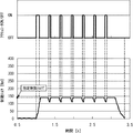
図4は、本発明の同期回転方式の減速装置における制動トルクの挙動の一例を示すタイムチャートである。同図に示すように、本発明の減速装置では、制動に際し、アクチュエータの1回目の作動ONにより、摩擦部材がブレーキディスクに押し付けられ、これに伴って磁石保持ディスクの回転速度が急激に減少するとともに、制動トルクが発生し急激に上昇する。ここで、アクチュエータの1回目の作動ONの時点から100%の制動トルクの発生までのタイムラグの時間よりも短い時間が経過した時点で、アクチュエータの作動をOFFに切り替える。すると、磁石保持ディスクは回転速度が0になる前に摩擦部材の押付けが解除されることから、制動トルクは100%に達する前にその上昇が止まり、上記した約0.2[s]の経過後に、磁石保持ディスクの回転速度の増加に伴って制動トルクは急激に降下し始める。 FIG. 4 is a time chart showing an example of the behavior of the braking torque in the synchronous rotation type reduction gear of the present invention. As shown in the figure, in the speed reducer of the present invention, when braking, the friction member is pressed against the brake disk when the actuator is turned on for the first time, and the rotational speed of the magnet holding disk rapidly decreases accordingly. At the same time, braking torque is generated and rapidly increases. Here, when the time shorter than the time lag from the time when the actuator is first turned on until the time when 100% braking torque is generated, the operation of the actuator is switched to OFF. Then, since the pressing force of the friction member is released before the rotation speed of the magnet holding disk becomes zero, the braking torque stops increasing before reaching 100%, and the above-mentioned about 0.2 [s] has passed. Later, as the rotation speed of the magnet holding disk increases, the braking torque begins to drop rapidly.
この瞬間に、アクチュエータの作動を2回目の作動ONに切り替える。すると、摩擦部材の押付けが再開することから、磁石保持ディスクの回転速度が減少に転じ、これに伴い制動トルクが上昇に転じる。ここで、再び、アクチュエータの作動(2回目の作動ON)をOFFに切り替える。すると、1回目の作動OFF時と同様に、制動トルクは100%に達する前にその上昇が止まり、上記した約0.2[s]の経過後に、制動トルクは急激に降下し始める。 At this moment, the operation of the actuator is switched to the second operation ON. Then, since the pressing of the friction member resumes, the rotation speed of the magnet holding disk starts to decrease, and the braking torque starts to increase accordingly. Here, the operation of the actuator (the second operation ON) is switched off again. Then, as in the case of the first operation OFF, the braking torque stops increasing before reaching 100%, and after about 0.2 [s], the braking torque starts to decrease rapidly.
以降、このようなアクチュエータの作動ON/OFFの切替えを繰り返し実行する。これにより、100%の制動トルクよりも低い制動トルクを発生させることが可能になる。とりわけ、アクチュエータの1回目の作動ON時間によって制動トルクを先ずは調整し、さらにそれ以降の作動ON時間および作動OFF時間を適切に設定することにより、発生する制動トルクがほぼ一定となり、制動トルクを調整することができる。以下に本発明の減速装置の具体的な構成を説明する。 Thereafter, such actuator ON / OFF switching is repeatedly executed. As a result, it is possible to generate a braking torque lower than 100% braking torque. In particular, by first adjusting the braking torque according to the first operation ON time of the actuator, and further appropriately setting the subsequent operation ON time and operation OFF time, the generated braking torque becomes substantially constant, and the braking torque is reduced. Can be adjusted. The specific configuration of the speed reducer of the present invention will be described below.
前記図2に示すように、本発明の減速装置は、制動ディスク1(制動部材)の回転速度を検出する回転速度検出器21と、アクチュエータ9の動作を制御する制御装置30と、を備える。
As shown in FIG. 2, the speed reduction device of the present invention includes a
回転速度検出器21としては、例えば、エンコーダを用いることができ、この場合、制動ディスク1に突起を設け、制動ディスク1が回転している際にその突起の単位時間当たりの周回数をカウントすることにより、制動ディスク1の実回転速度(回転数)を検出できる。もっとも、制動ディスク1は回転軸11と一体で回転するため、回転軸11の回転速度を検出しても構わない。
As the
制御装置30は、信号受信部31、記憶部32、演算部33および出力部34から構成される。信号受信部31は、指定の制動トルクによる制動に関する信号を受信する。指定の制動トルクは、運転手が走行状況に応じて所望し、運転手の操作により発信されたり、減速装置がブレーキ統合システムに組み込まれている場合は、そのブレーキ統合システムの制御装置が主ブレーキなどの動作を踏まえつつ状況に応じて最適なものを演算し、これにより発信されたりする。また、信号受信部31は、回転速度検出器21に接続されており、当該検出器21で検出した制動ディスク1の実回転速度に関する信号も受信する。
The
記憶部32には、信号受信部31で指定の制動トルクに関する信号を受信したときに、その指定の制動トルク、および回転速度検出器21によって検出した制動ディスク1の実回転速度Vsaに応じ、アクチュエータの1回目の作動ON時間、2回目以降の作動ON時間および作動OFF時間を決定するために、アクチュエータ作動時間決定用のデータテーブルが登録されている。指定の制動トルクを発生させるには、アクチュエータの作動ON/OFFの切替えを繰り返し実行する必要があり、その際に、アクチュエータの作動ON/OFFに伴う制動トルクの発生/消失のタイムラグを踏まえ、そのタイムラグの時間よりも短いアクチュエータの作動ON時間および作動OFF時間を適切に設定するためである。
The
図5にアクチュエータ作動時間決定用のデータテーブルの一例を示す。同図に示すように、データテーブルは、指定の制動トルクTおよび制動ディスクの実回転速度Vsaをそれぞれ段階的に区分し、指定の制動トルクTおよび制動ディスクの実回転速度Vsaごとに、指定の制動トルクTが発生するように、アクチュエータの1回目の作動ON時間、2回目以降の作動ON時間および作動OFF時間を定めたものである。これらの作動ON/OFF時間は予備試験により導き出したものである。なお、図5では、指定の制動トルクTを40〜160[Nm]まで40[Nm]ピッチで区分し、制動ディスクの実回転速度Vsaを1200〜2100[rpm]まで300[rpm]ピッチで区分した場合を例示している。 FIG. 5 shows an example of a data table for determining the actuator operation time. As shown in the figure, the data table divides the designated braking torque T and the actual rotational speed Vsa of the braking disk in stages, and designates the specified braking torque T and the actual rotational speed Vsa of the braking disk for each designated level. The first operation ON time of the actuator, the second operation ON time, and the operation OFF time are determined so that the braking torque T is generated. These operation ON / OFF times are derived from preliminary tests. In FIG. 5, the designated braking torque T is divided into 40 to 160 [Nm] at a pitch of 40 [Nm], and the actual rotational speed Vsa of the braking disk is divided into a pitch of 1200 to 2100 [rpm] at a pitch of 300 [rpm]. The case is shown as an example.
演算部33は、アクチュエータ作動時間決定用のデータテーブル(例えば前記図5)に基づき、指定の制動トルクTおよび制動ディスクの実回転速度Vsaに対応するアクチュエータの1回目の作動ON時間、2回目以降の作動ON時間および作動OFF時間を選定する演算処理を行う。その際、データテーブルに、該当する指定の制動トルクTおよび制動ディスクの実回転速度Vsaがいずれも登録されている場合は、その区分の作動ON/OFF時間を選定する。一方、データテーブルに、該当する指定の制動トルクTが登録されていなかったり、該当する制動ディスクの実回転速度Vsaが登録されていない場合は、線形補間により、該当する指定の制動トルクTおよび制動ディスクの実回転速度Vsaに対応する作動ON/OFF時間を算出し、選定する。
Based on the data table for determining the actuator operation time (for example, FIG. 5), the
出力部34は、演算部33による演算処理結果に従って、アクチュエータ9の電動モータ10に駆動信号(作動ON/OFF信号)を出力する。
The
このような構成の減速装置による制動動作について以下に説明する。
図6は、本発明の減速装置による制動動作を示すフローチャートである。ステップ#5にて、運転手の操作またはブレーキ統合システムの制御装置により、指定の制動トルクTによる制動の指令信号が発信され、この信号を制御装置30が受信すると、制動モードに移行する。これに伴い、ステップ#10にて、制御装置30は、回転速度検出器21より検出信号を受信し、制動ディスク1の実回転速度Vsaを取得する。
The braking operation by the speed reducer having such a configuration will be described below.
FIG. 6 is a flowchart showing a braking operation by the speed reducer of the present invention. In
これに続いて、ステップ#15にて、制御装置30は、指定の制動トルクTと、ステップ#10で取得した制動ディスク1の実回転速度Vsaとから、上記アクチュエータ作動時間決定用のデータテーブル(例えば前記図5)に基づき、その指定の制動トルクTおよび制動ディスクの実回転速度Vsaに対応するアクチュエータの作動ON/OFF時間を選定する。具体例を挙げると、指定の制動トルクTが140[Nm]であり、制動ディスク1の実回転速度Vsaが1500[rpm]である場合、データテーブルに140[Nm]の制動トルクTが登録されていないことから、120[Nm]と160[Nm]の区分の作動ON/OFF時間を線形補間し、アクチュエータの1回目の作動ON時間は0.165[s]、2回目以降の作動ON時間は0.050[s]、作動OFF時間は0.270[s]となる。
Subsequently, at
そして、ステップ#20にて、制御装置30は、ステップ#15で選定した作動ON/OFF時間を設定し、その作動ON/OFF時間の駆動信号(作動ON/OFF信号)を摩擦ブレーキのアクチュエータに出力し、アクチュエータの作動ON/OFFを繰り返させる。これにより、摩擦部材がブレーキディスクに繰り返し押し付けられる。その際、前記図4に示すように、アクチュエータの1回目の作動ONとこれに続く作動OFFにより、制動トルクは100%に達することなく、指定の制動トルクTに留まった後に下降し始め、次いでアクチュエータの2回目の作動ONとこれに続く作動OFFにより、制動トルクは再び上昇して指定の制動トルクTに留まった後に下降し始め、これが繰り返される。こうして、発生する制動トルクがほぼ一定に調整され、制動ディスクに指定の制動トルクTが作用するようになる。
In
このようなアクチュエータの作動ON/OFFを繰り返す制御の制動動作を実行して、アクチュエータ9による摩擦部材の押付け/解除を繰り返し、これに伴って磁石保持ディスク4の回転速度を制御することにより、発生する制動トルクがほぼ一定になり、その結果として、指定の制動トルクTを発生させることができる。
It is generated by executing such a braking operation for controlling ON / OFF of the actuator repeatedly, repeatedly pressing / releasing the friction member by the
その他本発明は上記の実施形態に限定されず、本発明の趣旨を逸脱しない範囲で、種々の変更が可能である。例えば、上記の実施形態ではディスク型の同期回転方式の減速装置を示しているが、ドラム型であっても構わない。ドラム型の場合、車両の回転軸に制動部材として円筒状の制動ドラムが固定され、この制動ドラムの内側に、磁石保持部材として、制動ドラムの内周面に対向して円周方向にわたり複数の永久磁石を保持した磁石保持ドラムが配設され、この磁石保持ドラムが回転軸に回転可能に支持された態様となる。 In addition, the present invention is not limited to the above-described embodiment, and various modifications can be made without departing from the spirit of the present invention. For example, in the above embodiment, a disk type synchronous rotation type reduction device is shown, but a drum type may be used. In the case of the drum type, a cylindrical braking drum is fixed as a braking member on the rotating shaft of the vehicle, and a plurality of magnet holding members are arranged inside the braking drum as opposed to the inner peripheral surface of the braking drum in the circumferential direction. A magnet holding drum holding a permanent magnet is provided, and the magnet holding drum is rotatably supported on the rotating shaft.
また、制動時に磁石保持部材の回転を抑える摩擦ブレーキとしては、電動式直動アクチュエータを駆動源とし、磁石保持部材と別体のブレーキディスクを一対のブレーキパッド(摩擦部材)で挟み込むディスクブレーキに限らない。例えば、そのブレーキディスクに一方向のみから摩擦部材を押し付けるものであってもよいし、磁石保持部材に直接摩擦部材を押し付けるものであっても構わない。 In addition, the friction brake that suppresses the rotation of the magnet holding member during braking is limited to a disc brake that uses an electric linear actuator as a drive source and sandwiches a brake disc separate from the magnet holding member between a pair of brake pads (friction members). Absent. For example, the friction member may be pressed against the brake disk from only one direction, or the friction member may be pressed directly against the magnet holding member.
本発明の渦電流式減速装置は、あらゆる車両の補助ブレーキとして有用である。 The eddy current type speed reducer of the present invention is useful as an auxiliary brake for any vehicle.
1:制動ディスク、 2:放熱フィン、 3:環状部材、
4:磁石保持ディスク、 5:永久磁石、 6:ブレーキディスク、
7:ブレーキキャリパ、 8a、8b:ブレーキパッド、
9:電動式直動アクチュエータ、 10:電動モータ、 11:回転軸、
12:連結軸、 13:スリーブ、 14:ナット、
15a、15b:軸受、 16a、16b:シール部材、 17:ブラケット、
18:軸受、 19a、19b:シール部材、 20:磁石カバー、
21:回転速度検出器、 30:制御装置、 31:信号受信部、
32:記憶部、 33:演算部、 34:出力部
1: braking disk, 2: heat radiation fin, 3: annular member,
4: magnet holding disc, 5: permanent magnet, 6: brake disc,
7: Brake caliper, 8a, 8b: Brake pad,
9: Electric linear actuator, 10: Electric motor, 11: Rotating shaft,
12: connecting shaft, 13: sleeve, 14: nut,
15a, 15b: bearing, 16a, 16b: seal member, 17: bracket,
18: Bearing, 19a, 19b: Seal member, 20: Magnet cover,
21: Rotational speed detector, 30: Control device, 31: Signal receiver,
32: Storage unit, 33: Calculation unit, 34: Output unit
Claims (1)
この制動部材に円周方向にわたり交互に向きの異なる磁界を作用させる複数の永久磁石を保持し、回転軸に回転可能に支持された磁石保持部材と、
制動時に磁石保持部材に摩擦部材を押し付けるアクチュエータを有する摩擦ブレーキと、を備えた渦電流式減速装置であって、
制動部材の回転速度を検出する回転速度検出器と、
アクチュエータの動作を制御する制御装置と、を備えており、
制御装置は、
(ステップ1)指定の制動トルクによる制動の指令が与えられると、回転速度検出器より制動部材の実回転速度を取得すること、
(ステップ2)制動トルクおよび制動部材の回転速度ごとに予め定められたデータテーブルから、ステップ1で取得した指定の制動トルクおよび制動部材の実回転速度に対応して、アクチュエータの1回目の作動ON時間、2回目以降の作動ON時間および作動OFF時間を選定すること、
(ステップ3)ステップ2で選定したアクチュエータの1回目の作動ON時間、2回目以降の作動ON時間および作動OFF時間でアクチュエータの作動ON/OFFを繰り返すこと、の一連の各ステップを実行すること、
を特徴とする渦電流式減速装置。 A braking member fixed to the rotating shaft of the vehicle;
A magnet holding member that holds a plurality of permanent magnets that alternately apply different magnetic fields to the braking member in the circumferential direction, and is rotatably supported on a rotating shaft;
An eddy current reduction device comprising: a friction brake having an actuator that presses the friction member against the magnet holding member during braking;
A rotational speed detector for detecting the rotational speed of the braking member;
A control device for controlling the operation of the actuator,
The control device
(Step 1) When a command for braking by a designated braking torque is given, acquiring the actual rotational speed of the braking member from the rotational speed detector;
(Step 2) The actuator is turned on for the first time according to the specified braking torque and the actual rotational speed of the braking member acquired in Step 1 from the data table determined in advance for each braking torque and the rotational speed of the braking member. Select the time, the second operation ON time and the operation OFF time,
(Step 3) Executing a series of steps of repeating the operation ON / OFF of the actuator at the first operation ON time, the second operation ON time and the operation OFF time of the actuator selected in Step 2;
An eddy current type speed reducer characterized by
Priority Applications (1)
| Application Number | Priority Date | Filing Date | Title |
|---|---|---|---|
| JP2012196771A JP5772771B2 (en) | 2012-09-07 | 2012-09-07 | Eddy current reducer |
Applications Claiming Priority (1)
| Application Number | Priority Date | Filing Date | Title |
|---|---|---|---|
| JP2012196771A JP5772771B2 (en) | 2012-09-07 | 2012-09-07 | Eddy current reducer |
Publications (2)
| Publication Number | Publication Date |
|---|---|
| JP2014054074A JP2014054074A (en) | 2014-03-20 |
| JP5772771B2 true JP5772771B2 (en) | 2015-09-02 |
Family
ID=50612031
Family Applications (1)
| Application Number | Title | Priority Date | Filing Date |
|---|---|---|---|
| JP2012196771A Active JP5772771B2 (en) | 2012-09-07 | 2012-09-07 | Eddy current reducer |
Country Status (1)
| Country | Link |
|---|---|
| JP (1) | JP5772771B2 (en) |
Families Citing this family (1)
| Publication number | Priority date | Publication date | Assignee | Title |
|---|---|---|---|---|
| CN114771284B (en) * | 2022-05-31 | 2023-01-03 | 深圳市好盈科技股份有限公司 | Intelligent drag brake method and device, model climbing vehicle and storage medium |
Family Cites Families (5)
| Publication number | Priority date | Publication date | Assignee | Title |
|---|---|---|---|---|
| JP5023617B2 (en) * | 2006-08-25 | 2012-09-12 | 住友金属工業株式会社 | Braking force estimation method, estimated braking force calculation device, braking force control device, and eddy current reduction device for eddy current reduction device |
| JP2009038891A (en) * | 2007-08-01 | 2009-02-19 | Nissan Motor Co Ltd | Power conversion apparatus and its control method |
| JP5260382B2 (en) * | 2009-03-30 | 2013-08-14 | 公益財団法人鉄道総合技術研究所 | Eddy current brake control device |
| JP5447003B2 (en) * | 2010-03-02 | 2014-03-19 | 新日鐵住金株式会社 | Eddy current reducer with power regeneration function |
| JP5606768B2 (en) * | 2010-04-07 | 2014-10-15 | 日野自動車株式会社 | Retarder control device, retarder control method, and vehicle having retarder control device |
-
2012
- 2012-09-07 JP JP2012196771A patent/JP5772771B2/en active Active
Also Published As
| Publication number | Publication date |
|---|---|
| JP2014054074A (en) | 2014-03-20 |
Similar Documents
| Publication | Publication Date | Title |
|---|---|---|
| US9333953B2 (en) | Electric parking brake system | |
| US10479342B2 (en) | Electrically powered brake device | |
| US9797462B2 (en) | Electric linear motion actuator and electric brake system | |
| US9855934B2 (en) | Electric brake system with parking function | |
| JP6182314B2 (en) | Electric brake device | |
| JP5613412B2 (en) | Eddy current reducer | |
| WO2010110027A1 (en) | Brake device for in-wheel motor | |
| JP2004122838A (en) | Electric parking brake system and method for controlling electric parking brake system | |
| JP6505399B2 (en) | Load sensor for vehicle brake device, electric linear actuator and electric brake device | |
| JP4659461B2 (en) | Vehicle wheel motor and control method thereof | |
| JP2021060092A (en) | Electromagnetic brake device | |
| JP6314399B2 (en) | Eddy current reducer | |
| JP5772771B2 (en) | Eddy current reducer | |
| JP5783151B2 (en) | Eddy current reducer | |
| JP2018095072A (en) | Electric brake system and method of setting pressing force-current characteristics | |
| JP4495621B2 (en) | Electric brake device for vehicle | |
| JP2010203562A (en) | Electric brake | |
| JP2003104195A (en) | Electric brake device | |
| JP2011097696A (en) | Eddy current type reduction gear | |
| JP2010203561A (en) | Electric brake | |
| KR101575280B1 (en) | Brake system for vehicle and control method | |
| JP4233935B2 (en) | Brake device | |
| JP2010090994A (en) | Electric brake device | |
| JP6201793B2 (en) | Eddy current reducer | |
| JP2005088787A (en) | Brake controller |
Legal Events
| Date | Code | Title | Description |
|---|---|---|---|
| A621 | Written request for application examination |
Free format text: JAPANESE INTERMEDIATE CODE: A621 Effective date: 20140811 |
|
| RD02 | Notification of acceptance of power of attorney |
Free format text: JAPANESE INTERMEDIATE CODE: A7422 Effective date: 20141202 |
|
| A977 | Report on retrieval |
Free format text: JAPANESE INTERMEDIATE CODE: A971007 Effective date: 20150520 |
|
| TRDD | Decision of grant or rejection written | ||
| A01 | Written decision to grant a patent or to grant a registration (utility model) |
Free format text: JAPANESE INTERMEDIATE CODE: A01 Effective date: 20150602 |
|
| A61 | First payment of annual fees (during grant procedure) |
Free format text: JAPANESE INTERMEDIATE CODE: A61 Effective date: 20150615 |
|
| R151 | Written notification of patent or utility model registration |
Ref document number: 5772771 Country of ref document: JP Free format text: JAPANESE INTERMEDIATE CODE: R151 |
|
| S533 | Written request for registration of change of name |
Free format text: JAPANESE INTERMEDIATE CODE: R313533 |
|
| R350 | Written notification of registration of transfer |
Free format text: JAPANESE INTERMEDIATE CODE: R350 |