JP5771621B2 - Non-aqueous battery separator, non-aqueous battery using the same, and method for producing non-aqueous battery separator - Google Patents
Non-aqueous battery separator, non-aqueous battery using the same, and method for producing non-aqueous battery separator Download PDFInfo
- Publication number
- JP5771621B2 JP5771621B2 JP2012540764A JP2012540764A JP5771621B2 JP 5771621 B2 JP5771621 B2 JP 5771621B2 JP 2012540764 A JP2012540764 A JP 2012540764A JP 2012540764 A JP2012540764 A JP 2012540764A JP 5771621 B2 JP5771621 B2 JP 5771621B2
- Authority
- JP
- Japan
- Prior art keywords
- separator
- polymer
- melting point
- vinyl
- aqueous battery
- Prior art date
- Legal status (The legal status is an assumption and is not a legal conclusion. Google has not performed a legal analysis and makes no representation as to the accuracy of the status listed.)
- Active
Links
Classifications
-
- H—ELECTRICITY
- H01—ELECTRIC ELEMENTS
- H01M—PROCESSES OR MEANS, e.g. BATTERIES, FOR THE DIRECT CONVERSION OF CHEMICAL ENERGY INTO ELECTRICAL ENERGY
- H01M50/00—Constructional details or processes of manufacture of the non-active parts of electrochemical cells other than fuel cells, e.g. hybrid cells
- H01M50/40—Separators; Membranes; Diaphragms; Spacing elements inside cells
- H01M50/409—Separators, membranes or diaphragms characterised by the material
- H01M50/411—Organic material
- H01M50/414—Synthetic resins, e.g. thermoplastics or thermosetting resins
-
- H—ELECTRICITY
- H01—ELECTRIC ELEMENTS
- H01M—PROCESSES OR MEANS, e.g. BATTERIES, FOR THE DIRECT CONVERSION OF CHEMICAL ENERGY INTO ELECTRICAL ENERGY
- H01M10/00—Secondary cells; Manufacture thereof
- H01M10/05—Accumulators with non-aqueous electrolyte
- H01M10/052—Li-accumulators
-
- C—CHEMISTRY; METALLURGY
- C08—ORGANIC MACROMOLECULAR COMPOUNDS; THEIR PREPARATION OR CHEMICAL WORKING-UP; COMPOSITIONS BASED THEREON
- C08G—MACROMOLECULAR COMPOUNDS OBTAINED OTHERWISE THAN BY REACTIONS ONLY INVOLVING UNSATURATED CARBON-TO-CARBON BONDS
- C08G18/00—Polymeric products of isocyanates or isothiocyanates
- C08G18/04—Polymeric products of isocyanates or isothiocyanates with vinyl compounds
-
- C—CHEMISTRY; METALLURGY
- C08—ORGANIC MACROMOLECULAR COMPOUNDS; THEIR PREPARATION OR CHEMICAL WORKING-UP; COMPOSITIONS BASED THEREON
- C08G—MACROMOLECULAR COMPOUNDS OBTAINED OTHERWISE THAN BY REACTIONS ONLY INVOLVING UNSATURATED CARBON-TO-CARBON BONDS
- C08G18/00—Polymeric products of isocyanates or isothiocyanates
- C08G18/06—Polymeric products of isocyanates or isothiocyanates with compounds having active hydrogen
- C08G18/28—Polymeric products of isocyanates or isothiocyanates with compounds having active hydrogen characterised by the compounds used containing active hydrogen
- C08G18/40—High-molecular-weight compounds
- C08G18/4009—Two or more macromolecular compounds not provided for in one single group of groups C08G18/42 - C08G18/64
-
- H—ELECTRICITY
- H01—ELECTRIC ELEMENTS
- H01M—PROCESSES OR MEANS, e.g. BATTERIES, FOR THE DIRECT CONVERSION OF CHEMICAL ENERGY INTO ELECTRICAL ENERGY
- H01M50/00—Constructional details or processes of manufacture of the non-active parts of electrochemical cells other than fuel cells, e.g. hybrid cells
- H01M50/40—Separators; Membranes; Diaphragms; Spacing elements inside cells
- H01M50/403—Manufacturing processes of separators, membranes or diaphragms
-
- H—ELECTRICITY
- H01—ELECTRIC ELEMENTS
- H01M—PROCESSES OR MEANS, e.g. BATTERIES, FOR THE DIRECT CONVERSION OF CHEMICAL ENERGY INTO ELECTRICAL ENERGY
- H01M50/00—Constructional details or processes of manufacture of the non-active parts of electrochemical cells other than fuel cells, e.g. hybrid cells
- H01M50/40—Separators; Membranes; Diaphragms; Spacing elements inside cells
- H01M50/409—Separators, membranes or diaphragms characterised by the material
- H01M50/411—Organic material
- H01M50/414—Synthetic resins, e.g. thermoplastics or thermosetting resins
- H01M50/417—Polyolefins
-
- H—ELECTRICITY
- H01—ELECTRIC ELEMENTS
- H01M—PROCESSES OR MEANS, e.g. BATTERIES, FOR THE DIRECT CONVERSION OF CHEMICAL ENERGY INTO ELECTRICAL ENERGY
- H01M50/00—Constructional details or processes of manufacture of the non-active parts of electrochemical cells other than fuel cells, e.g. hybrid cells
- H01M50/40—Separators; Membranes; Diaphragms; Spacing elements inside cells
- H01M50/409—Separators, membranes or diaphragms characterised by the material
- H01M50/411—Organic material
- H01M50/429—Natural polymers
-
- H—ELECTRICITY
- H01—ELECTRIC ELEMENTS
- H01M—PROCESSES OR MEANS, e.g. BATTERIES, FOR THE DIRECT CONVERSION OF CHEMICAL ENERGY INTO ELECTRICAL ENERGY
- H01M50/00—Constructional details or processes of manufacture of the non-active parts of electrochemical cells other than fuel cells, e.g. hybrid cells
- H01M50/40—Separators; Membranes; Diaphragms; Spacing elements inside cells
- H01M50/409—Separators, membranes or diaphragms characterised by the material
- H01M50/44—Fibrous material
-
- H—ELECTRICITY
- H01—ELECTRIC ELEMENTS
- H01M—PROCESSES OR MEANS, e.g. BATTERIES, FOR THE DIRECT CONVERSION OF CHEMICAL ENERGY INTO ELECTRICAL ENERGY
- H01M50/00—Constructional details or processes of manufacture of the non-active parts of electrochemical cells other than fuel cells, e.g. hybrid cells
- H01M50/40—Separators; Membranes; Diaphragms; Spacing elements inside cells
- H01M50/409—Separators, membranes or diaphragms characterised by the material
- H01M50/443—Particulate material
-
- H—ELECTRICITY
- H01—ELECTRIC ELEMENTS
- H01M—PROCESSES OR MEANS, e.g. BATTERIES, FOR THE DIRECT CONVERSION OF CHEMICAL ENERGY INTO ELECTRICAL ENERGY
- H01M50/00—Constructional details or processes of manufacture of the non-active parts of electrochemical cells other than fuel cells, e.g. hybrid cells
- H01M50/40—Separators; Membranes; Diaphragms; Spacing elements inside cells
- H01M50/409—Separators, membranes or diaphragms characterised by the material
- H01M50/449—Separators, membranes or diaphragms characterised by the material having a layered structure
- H01M50/454—Separators, membranes or diaphragms characterised by the material having a layered structure comprising a non-fibrous layer and a fibrous layer superimposed on one another
-
- H—ELECTRICITY
- H01—ELECTRIC ELEMENTS
- H01M—PROCESSES OR MEANS, e.g. BATTERIES, FOR THE DIRECT CONVERSION OF CHEMICAL ENERGY INTO ELECTRICAL ENERGY
- H01M50/00—Constructional details or processes of manufacture of the non-active parts of electrochemical cells other than fuel cells, e.g. hybrid cells
- H01M50/40—Separators; Membranes; Diaphragms; Spacing elements inside cells
- H01M50/489—Separators, membranes, diaphragms or spacing elements inside the cells, characterised by their physical properties, e.g. swelling degree, hydrophilicity or shut down properties
-
- Y—GENERAL TAGGING OF NEW TECHNOLOGICAL DEVELOPMENTS; GENERAL TAGGING OF CROSS-SECTIONAL TECHNOLOGIES SPANNING OVER SEVERAL SECTIONS OF THE IPC; TECHNICAL SUBJECTS COVERED BY FORMER USPC CROSS-REFERENCE ART COLLECTIONS [XRACs] AND DIGESTS
- Y02—TECHNOLOGIES OR APPLICATIONS FOR MITIGATION OR ADAPTATION AGAINST CLIMATE CHANGE
- Y02E—REDUCTION OF GREENHOUSE GAS [GHG] EMISSIONS, RELATED TO ENERGY GENERATION, TRANSMISSION OR DISTRIBUTION
- Y02E60/00—Enabling technologies; Technologies with a potential or indirect contribution to GHG emissions mitigation
- Y02E60/10—Energy storage using batteries
-
- Y—GENERAL TAGGING OF NEW TECHNOLOGICAL DEVELOPMENTS; GENERAL TAGGING OF CROSS-SECTIONAL TECHNOLOGIES SPANNING OVER SEVERAL SECTIONS OF THE IPC; TECHNICAL SUBJECTS COVERED BY FORMER USPC CROSS-REFERENCE ART COLLECTIONS [XRACs] AND DIGESTS
- Y02—TECHNOLOGIES OR APPLICATIONS FOR MITIGATION OR ADAPTATION AGAINST CLIMATE CHANGE
- Y02P—CLIMATE CHANGE MITIGATION TECHNOLOGIES IN THE PRODUCTION OR PROCESSING OF GOODS
- Y02P70/00—Climate change mitigation technologies in the production process for final industrial or consumer products
- Y02P70/50—Manufacturing or production processes characterised by the final manufactured product
Description
本願は、日本国で2010年10月27日に出願した特願2010−240329の優先権を主張するものであり、その全体を参照により本出願の一部をなすものとして引用する。 This application claims the priority of Japanese Patent Application No. 2010-240329 for which it applied in Japan on October 27, 2010, The whole is referred as forming a part of this application by reference.
本発明は非水系電池の構成材料として有用な電池用セパレータ及びそれを用いた非水系電池に関し、さらに前記電池用セパレータの製造方法に関する。 The present invention relates to a battery separator useful as a constituent material of a non-aqueous battery and a non-aqueous battery using the same, and further relates to a method for manufacturing the battery separator.
近年、電子機器のコードレス化に対応するため、軽量で高起電力、高エネルギーが得られる電源として、リチウム電池(リチウム一次電池)やリチウムイオン二次電池等の非水系電池が注目を集めている。例えば、円筒形リチウム二次電池などは、携帯電話やノート型パソコン等に用いられるため大量に生産されており、その生産量は年々増加している。さらに、非水系電池は、次世代の電気自動車用のエネルギー源としても注目され、更なる電気抵抗抑制による高出力化の要求も高くなっている。 In recent years, non-aqueous batteries such as lithium batteries (lithium primary batteries) and lithium ion secondary batteries have been attracting attention as power sources that are lightweight, have high electromotive force, and high energy in order to cope with cordless electronic devices. . For example, cylindrical lithium secondary batteries and the like are produced in large quantities because they are used in mobile phones, notebook computers, and the like, and their production volume is increasing year by year. Further, non-aqueous batteries are attracting attention as energy sources for next-generation electric vehicles, and there is an increasing demand for higher output by further suppressing electric resistance.
現在非水系電池のセパレータとしては、延伸法により微多孔化されたポリオレフィンよりなる多孔性膜のフィルムが使用されている。しかしながら、このフィルムはポリマー自体に電解液に対する膨潤性がないため、抵抗値の高いものしか得られず、高出力化の要求に答えるものにはならなかった。 At present, as a separator for a non-aqueous battery, a porous film made of polyolefin microporous by a stretching method is used. However, since this film does not swell to the electrolyte in the polymer itself, only a high resistance value can be obtained, and it has not been able to meet the demand for higher output.
そこで、特許文献1(特開平5−226002号公報)には、エーテル系ポリウレタン、LiAF6および炭酸プロピレンを主成分とするリチウム二次電池用ゲル状電解質が開示されている。
この発明では、電極と電解質の密着性を良好にして、電解質溶液なみの界面インピーダンスを得ることが可能なリチウム二次電池を提供することができる。Therefore, Patent Document 1 (Japanese Patent Laid-Open No. 5-226002) discloses a gel electrolyte for a lithium secondary battery containing ether-based polyurethane, LiAF 6 and propylene carbonate as main components.
According to the present invention, it is possible to provide a lithium secondary battery capable of improving the adhesion between the electrode and the electrolyte and obtaining an interface impedance similar to that of the electrolyte solution.
また、特許文献2(特開2004−31084号公報)には、基材の片面に微多孔膜を有する高分子樹脂被覆層を設けた、非水系電池用セパレータが開示されている。
この文献では、加工性に優れ、ある一定レベルの電解液膨潤性を得ることが出来、さらに電解物質の脱落・移動に伴う内部短絡を防止できる非水系電池を得ることができる。Patent Document 2 (Japanese Patent Application Laid-Open No. 2004-31084) discloses a nonaqueous battery separator in which a polymer resin coating layer having a microporous film is provided on one surface of a base material.
In this document, it is possible to obtain a non-aqueous battery that is excellent in processability, can obtain a certain level of electrolyte swellability, and can prevent internal short-circuiting due to dropping and movement of the electrolytic substance.
しかしながら、特許文献1のゲル状電解質では、保液性をある程度高めることはできるものの、保液性の向上には限界があるとともに、高分子膜のみで皮膜層を形成しているため、十分な強度を保てない。また、一般的なエーテル系ポリウレタンのため、電解液に対する膨潤性が十分ではない。そのため、電池の内部抵抗が高くなり、放電レート特性に優れた電池を得ることは出来ない。 However, in the gel electrolyte of Patent Document 1, although the liquid retention can be improved to some extent, there is a limit to the improvement of the liquid retention, and since the film layer is formed only by the polymer film, it is sufficient. Can't keep strength. Moreover, since it is a general ether type polyurethane, the swelling property with respect to electrolyte solution is not enough. For this reason, the internal resistance of the battery is increased, and a battery having excellent discharge rate characteristics cannot be obtained.
また、特許文献2のセパレータでは、基材との複合により加工性は改善されているものの、使用している樹脂の膨潤性が低く、特許文献1と同様に、放電レート特性に優れた電池とならない。
また、特許文献1及び2とも電池の温度上昇に際し、電気抵抗の増大により電池反応を遮断するような安全装置も付与されていない。Moreover, in the separator of Patent Document 2, although the workability is improved by combining with the base material, the swelling property of the resin used is low, and, as in Patent Document 1, the battery has excellent discharge rate characteristics. Don't be.
Further, neither of Patent Documents 1 and 2 is provided with a safety device that interrupts the battery reaction due to an increase in electrical resistance when the temperature of the battery rises.
本発明の目的は、完全膜となる高膨潤の特殊ウレタン樹脂を使用することで、低抵抗化とセパレータ強度とを両立できる非水系電池用セパレータを提供することにある。
本発明の別の目的は、低抵抗化と耐短絡性の双方を実現できる非水系電池用セパレータを提供することにある。An object of the present invention is to provide a non-aqueous battery separator that can achieve both low resistance and separator strength by using a highly swollen special urethane resin that forms a complete film.
Another object of the present invention is to provide a non-aqueous battery separator capable of realizing both low resistance and short circuit resistance.
本発明のさらに別の目的は、電池が異常に加熱した場合であっても、耐熱性ポリマーよりなる基材により、セパレータの熱収縮による変形を防止できる非水系電池用セパレータを提供することにある。
本発明のさらに別の目的は、速やかに溶融膜を形成してシャットダウン特性を発揮できるだけでなく、耐電解液性をも有する非水系電池用セパレータを提供することにある。Still another object of the present invention is to provide a separator for a non-aqueous battery that can prevent deformation due to thermal contraction of the separator by a base material made of a heat-resistant polymer even when the battery is abnormally heated. .
Still another object of the present invention is to provide a separator for a non-aqueous battery that not only forms a molten film quickly and exhibits shutdown characteristics, but also has resistance to electrolyte.
本発明のさらに別の目的は、各層との一体性に優れ、電池を成型する工程でのとり扱い性に優れる非水系電池用セパレータを提供することにある。 Still another object of the present invention is to provide a separator for a non-aqueous battery that is excellent in integrity with each layer and excellent in handleability in the process of molding the battery.
本発明の他の目的は、このような非水系電池用セパレータを効率よく製造することができる製造方法を提供することにある。
本発明のさらに他の目的は、高出力であるとともに安全性にも優れている非水系電池を提供することにある。Another object of the present invention is to provide a production method capable of efficiently producing such a non-aqueous battery separator.
Still another object of the present invention is to provide a non-aqueous battery that has high output and excellent safety.
本発明者等は上記目的を達成すべく鋭意検討を行った結果、特殊なウレタン樹脂よりなる電解液膨潤性樹脂層と基材層とを一体化することで、このウレタン樹脂に由来した電解液膨潤性により低抵抗化が可能であるだけでなく、一体化に由来したセパレータ強度の双方を両立できることを見出し、本発明を完成した。 As a result of intensive studies to achieve the above object, the present inventors have integrated an electrolyte-swellable resin layer made of a special urethane resin and a base material layer, and thereby an electrolyte derived from this urethane resin. The present inventors have found that not only the resistance can be lowered by the swelling property, but also the separator strength derived from the integration can be achieved at the same time.
すなわち、本発明は、片末端に2個の水酸基を有するビニル重合体(a1’)を主鎖とし、その側鎖に数平均分子量200〜800のポリオキシエチレン鎖を、ビニル重合体(a1)の全量に対して70質量%〜98質量%有する数平均分子量2000〜7000のビニル重合体(a1)と、
ポリエーテルポリオール(a2)とを含有するポリオール(A)と、
ポリイソシアネート(B)とを反応させて得られるウレタン樹脂(C)よりなる電解液膨潤性樹脂層が、繊維集合体よりなる基材層の少なくとも片面に形成され、両者が一体化していることを特徴とする非水系電池用セパレータである。That is, the present invention has a vinyl polymer (a1 ′) having two hydroxyl groups at one end as a main chain, and a polyoxyethylene chain having a number average molecular weight of 200 to 800 as a side chain. A vinyl polymer (a1) having a number average molecular weight of 2000 to 7000 having 70% by mass to 98% by mass with respect to the total amount of
A polyol (A) containing a polyether polyol (a2);
The electrolyte-swellable resin layer made of urethane resin (C) obtained by reacting with polyisocyanate (B) is formed on at least one side of the base material layer made of fiber aggregate, and both are integrated. It is the separator for non-aqueous batteries characterized.
前記ビニル重合体(a1)は、例えば、2個の水酸基と1個のメルカプト基とを有する連鎖移動剤(D)、及び、数平均分子量200〜800のポリオキシエチレン鎖を有するビニル単量体(e)を含むビニル単量体(E)を反応させて得られるものであってもよい。また、電解液膨潤性樹脂層は、実質的に無孔であってもよい。なお、ここで、実質的に無孔とは、電解液膨潤性樹脂層の透気度が5000秒/100cc以上である状態を意味する。 The vinyl polymer (a1) includes, for example, a chain transfer agent (D) having two hydroxyl groups and one mercapto group, and a vinyl monomer having a polyoxyethylene chain having a number average molecular weight of 200 to 800 It may be obtained by reacting a vinyl monomer (E) containing (e). Further, the electrolyte swellable resin layer may be substantially nonporous. Here, “substantially non-porous” means that the air permeability of the electrolyte-swellable resin layer is 5000 seconds / 100 cc or more.
好ましい実施態様では、前記基材層は、少なくとも耐熱性ポリマー層を含んでおり、前記耐熱性ポリマーは、融点が200℃を超える高融点ポリマーもしくは熱不融性ポリマーで構成されてもよい。例えば、前記耐熱性ポリマーは、全芳香族ポリアミド系ポリマー、ポリビニルアルコール系ポリマー、及びセルロース系ポリマーからなる群から選択された少なくとも一種で構成されていてもよい。 In a preferred embodiment, the base material layer includes at least a heat resistant polymer layer, and the heat resistant polymer may be composed of a high melting point polymer or a heat infusible polymer having a melting point exceeding 200 ° C. For example, the heat-resistant polymer may be composed of at least one selected from the group consisting of wholly aromatic polyamide polymers, polyvinyl alcohol polymers, and cellulose polymers.
また、前記基材層は、不織布で構成されているのが好ましく、このような不織布は、湿式不織布、乾式不織布、メルトブローン不織布、スパンボンド不織布、および静電紡糸不織布からなる群より選択された1種または2種以上の不織布または不織布積層体であってもよい。 The base material layer is preferably composed of a nonwoven fabric, and the nonwoven fabric is selected from the group consisting of a wet nonwoven fabric, a dry nonwoven fabric, a melt blown nonwoven fabric, a spunbond nonwoven fabric, and an electrospun nonwoven fabric. It may be a seed or two or more nonwoven fabrics or a nonwoven fabric laminate.
また、好ましい実施態様では、基材層は、耐熱性ポリマー層と、融点が100〜200℃の低融点ポリマーからなる低融点ポリマー層との積層体で形成されていてもよい。このような低融点ポリマー層は、例えば、平均繊維径1000nm以下のナノファイバーを含む不織布であってもよい。 In a preferred embodiment, the base material layer may be formed of a laminate of a heat resistant polymer layer and a low melting point polymer layer made of a low melting point polymer having a melting point of 100 to 200 ° C. Such a low melting point polymer layer may be, for example, a nonwoven fabric containing nanofibers having an average fiber diameter of 1000 nm or less.
前記低融点ポリマー層を形成する低融点ポリマーは、例えば、ポリオレフィン系ポリマー、エチレン−ビニルアルコール系共重合物、及びフッ素系ポリマーからなる群から選択される少なくとも一種で構成されていてもよい。 The low melting point polymer that forms the low melting point polymer layer may be composed of, for example, at least one selected from the group consisting of polyolefin polymers, ethylene-vinyl alcohol copolymers, and fluorine polymers.
本発明は、本発明の一実施態様である非水系電池用セパレータの製造方法についても包含し、前記製造方法の一実施態様は、
片末端に2個の水酸基を有するビニル重合体(a1’)を主鎖とし、その側鎖に数平均分子量200〜800のポリオキシエチレン鎖を、ビニル重合体(a1)の全量に対して70質量%〜98質量%有する数平均分子量2000〜7000のビニル重合体(a1)と、ポリエーテルポリオール(a2)とを含有するポリオール(A)、及び、ポリイソシアネート(B)を反応させて得られるウレタン樹脂(C)からシートまたはフィルムを作製する工程と、前記シートまたはフィルムを繊維集合体よりなる支持基材の少なくとも片面に対して貼りあわせる工程と、を含んでいる。The present invention also includes a method for producing a separator for a non-aqueous battery that is one embodiment of the present invention.
A vinyl polymer (a1 ′) having two hydroxyl groups at one end is used as a main chain, and a polyoxyethylene chain having a number average molecular weight of 200 to 800 is added to the side chain of the vinyl polymer (a1). Obtained by reacting a polyol (A) containing a vinyl polymer (a1) having a number average molecular weight of 2000 to 7000 and a polyether polyol (a2), and a polyisocyanate (B). A step of producing a sheet or film from the urethane resin (C), and a step of laminating the sheet or film to at least one side of a support substrate made of a fiber assembly.
また、前記製造方法の他の実施態様は、
片末端に2個の水酸基を有するビニル重合体(a1’)を主鎖とし、その側鎖に数平均分子量200〜800のポリオキシエチレン鎖を、ビニル重合体(a1)の全量に対して70質量%〜98質量%有する数平均分子量2000〜7000のビニル重合体(a1)と、ポリエーテルポリオール(a2)とを含有するポリオール(A)、及び、ポリイソシアネート(B)を反応させて得られるウレタン樹脂(C)の溶液または分散液を作製する工程と、前記溶液または分散液を繊維集合体よりなる支持基材に対して塗布または含浸する工程と、を含んでいる。Another embodiment of the manufacturing method is as follows:
A vinyl polymer (a1 ′) having two hydroxyl groups at one end is used as a main chain, and a polyoxyethylene chain having a number average molecular weight of 200 to 800 is added to the side chain of the vinyl polymer (a1). Obtained by reacting a polyol (A) containing a vinyl polymer (a1) having a number average molecular weight of 2000 to 7000 and a polyether polyol (a2), and a polyisocyanate (B). A step of preparing a solution or dispersion of the urethane resin (C), and a step of applying or impregnating the solution or dispersion to a support substrate made of a fiber assembly.
さらにまた、本発明は前記非水系電池用セパレータを使用した非水系電池についても包含する。 Furthermore, the present invention also includes a non-aqueous battery using the non-aqueous battery separator.
なお、請求の範囲および/または明細書に開示された少なくとも2つの構成要素のどのような組み合わせも、本発明に含まれる。特に、請求の範囲に記載された請求項の2つ以上のどのような組み合わせも本発明に含まれる。 It should be noted that any combination of at least two components disclosed in the claims and / or the specification is included in the present invention. In particular, any combination of two or more of the claims recited in the claims is included in the present invention.
本発明の非水系電池用セパレータを用いると、特定のウレタン樹脂に由来して、低抵抗化と強度の双方を実現できる非水系電池用セパレータを得ることができる。
さらに、ウレタン系樹脂が実質的に無孔のフィルムで形成される場合、電解質の離脱などによって生じる短絡を防止することが可能である。When the non-aqueous battery separator of the present invention is used, a non-aqueous battery separator capable of realizing both low resistance and strength can be obtained from a specific urethane resin.
Furthermore, when the urethane-based resin is formed of a substantially non-porous film, it is possible to prevent a short circuit caused by detachment of the electrolyte.
また、基材層が耐熱性ポリマーから形成される場合、電池が異常に加熱した場合であっても、セパレータの熱収縮による変形を防止し、非水系電池用セパレータの安全性を向上することができる。 In addition, when the base material layer is formed from a heat-resistant polymer, even when the battery is abnormally heated, deformation due to thermal contraction of the separator can be prevented, and the safety of the non-aqueous battery separator can be improved. it can.
さらに、必要に応じて基材層に低融点ポリマー層を形成することで、耐熱性ポリマー層が、電池が異常に加熱した場合であっても、速やかに低融点ポリマーが溶融膜を形成してシャットダウン特性を発揮でき、シャットダウン性能を付与することができる。 Furthermore, by forming a low melting point polymer layer on the base material layer as necessary, even when the heat resistant polymer layer abnormally heats the battery, the low melting point polymer quickly forms a molten film. Shutdown characteristics can be exhibited and shutdown performance can be imparted.
本発明の非水系電池用セパレータは、特殊なウレタン樹脂よりなる電解液膨潤性樹脂層が、繊維集合体よりなる基材層の少なくとも片面に形成され、両者が一体化することで構成されている。
好ましくは、前記電解液膨潤性樹脂層は、実質的に無孔のフィルムで完全膜状に形成されていてもよく、前記基材層は、耐熱性ポリマーよりなる繊維状物と、さらに必要に応じて低融点ポリマーの繊維状物との積層体で形成されていてもよい。The separator for a non-aqueous battery according to the present invention is formed by forming an electrolyte-swellable resin layer made of a special urethane resin on at least one surface of a base material layer made of a fiber assembly and integrating them. .
Preferably, the electrolyte-swellable resin layer may be formed in a complete film shape with a substantially non-porous film, and the base material layer further includes a fibrous material made of a heat-resistant polymer, and further necessary. Accordingly, it may be formed of a laminate with a fibrous material of a low melting point polymer.
(電解液膨潤性樹脂層)
電解液膨潤性樹脂層は、電解液膨潤性樹脂から形成され、前記電解液膨潤性樹脂としては、片末端に2個の水酸基を有するビニル重合体(a1’)を主鎖とし、その側鎖に数平均分子量200〜800のポリオキシエチレン鎖を、ビニル重合体(a1)の全量に対して70質量%〜98質量%有する数平均分子量2000〜7000のビニル重合体(a1)と、ポリエーテルポリオール(a2)とを含有するポリオール(A)、及び、ポリイソシアネート(B)を反応させて得られるウレタン樹脂(C)を使用することができる。(Electrolyte swellable resin layer)
The electrolyte swellable resin layer is formed from an electrolyte swellable resin, and the electrolyte swellable resin has a vinyl polymer (a1 ′) having two hydroxyl groups at one end as its main chain, and its side chain. A polyoxyethylene chain having a number average molecular weight of 200 to 800, a vinyl polymer (a1) having a number average molecular weight of 2000 to 7000 having a polyoxyethylene chain of 70% by mass to 98% by mass relative to the total amount of the vinyl polymer (a1), and a polyether. The urethane resin (C) obtained by reacting the polyol (A) containing the polyol (a2) and the polyisocyanate (B) can be used.
前記ウレタン樹脂(C)は、ポリエーテル構造を主鎖に有し、その側鎖としてビニル重合体(al)由来の構造を有するものである。前記ウレタン樹脂(C)は、前記ウレタン樹脂(C)の全量に対して前記ビニル重合体(a1)由来の構造を2質量%〜50質量%含むものを使用することが好ましい。 The urethane resin (C) has a polyether structure in the main chain, and has a structure derived from the vinyl polymer (al) as a side chain. The urethane resin (C) preferably contains 2% by mass to 50% by mass of the structure derived from the vinyl polymer (a1) with respect to the total amount of the urethane resin (C).
また、前記ウレタン樹脂(C)の側鎖を形成しうるビニル重合体(al)由来の構造は、ビニル重合体(a1’)を主鎖とし、その側鎖に数平均分子量200〜800(好ましくは300〜700)のポリオキシエチレン鎖を有する構造である。 The structure derived from the vinyl polymer (al) capable of forming a side chain of the urethane resin (C) has a vinyl polymer (a1 ′) as a main chain, and the side chain has a number average molecular weight of 200 to 800 (preferably Is a structure having 300 to 700) polyoxyethylene chains.
また、前記ウレタン樹脂(C)としては、イオン伝導性を向上させるうえで、50000〜150000の範囲の重量平均分子量を有するものを使用することが好ましく、前記重量平均分子量は60000〜130000の範囲であるのがより好ましい。 Moreover, as said urethane resin (C), when improving ion conductivity, it is preferable to use what has a weight average molecular weight of the range of 50000-150,000, and the said weight average molecular weight is the range of 60000-130,000. More preferably.
前記ウレタン樹脂(C)の製造に使用する前記ポリオール(A)としては、前記したとおり、片末端に2個の水酸基を有するビニル重合体(a1’)を主鎖とし、その側鎖に数平均分子量200〜800のポリオキシエチレン鎖を、ビニル重合体(a1)の全量に対し70質量%〜98質量%有する数平均分子量2000〜7000のビニル重合体(al)と、ポリエーテルポリオール(a2)とを含有するものを使用することが必須である。 As said polyol (A) used for manufacture of the said urethane resin (C), as mentioned above, the vinyl polymer (a1 ') which has two hydroxyl groups in one terminal is made into a main chain, and the number average is carried out in the side chain. A vinyl polymer (al) having a number average molecular weight of 2000 to 7000 having a polyoxyethylene chain having a molecular weight of 200 to 800 based on the total amount of the vinyl polymer (a1), and a polyether polyol (a2). It is essential to use those containing.
前記ウレタン樹脂(C)の製造に使用する片末端に2個の水酸基を有するビニル重合体(a1’)を主鎖とし、その側鎖に数平均分子量200〜800のポリオキシエチレン鎖を、ビニル重合体(a1)の全量に対して70質量%〜98質量%有する数平均分子量2000〜7000のビニル重合体(a1)としては、例えば2個の水酸基を有する連鎖移動剤の存在下で、数平均分子量200〜800のポリオキシエチレン鎖を有するビニル単量体(e)を含むビニル単量体(E)を重合することによって得られるものを使用することができる。 A vinyl polymer (a1 ′) having two hydroxyl groups at one end used for producing the urethane resin (C) is a main chain, and a polyoxyethylene chain having a number average molecular weight of 200 to 800 is added to the side chain of the vinyl polymer. As the vinyl polymer (a1) having a number average molecular weight of 2000 to 7000 having 70% by mass to 98% by mass with respect to the total amount of the polymer (a1), for example, in the presence of a chain transfer agent having two hydroxyl groups, Those obtained by polymerizing a vinyl monomer (E) containing a vinyl monomer (e) having a polyoxyethylene chain having an average molecular weight of 200 to 800 can be used.
具体的には、2個の水酸基とメルカプト基等を有する連鎖移動剤(D)の存在下で前記ビニル単量体(E)のラジカル重合を行い、前記メルカプト基を起点として前記ビニル単量体(E)が重合したものが挙げられる。 Specifically, radical polymerization of the vinyl monomer (E) is carried out in the presence of a chain transfer agent (D) having two hydroxyl groups and a mercapto group, and the vinyl monomer starts from the mercapto group. What polymerized (E) is mentioned.
得られたビニル重合体(a1)は、前記連鎖移動剤(D)由来の2個の水酸基を片末端に有するため、この2個の水酸基と後述するポリイソシアネート(B)の有するイソシアネート基とを反応することによってウレタン結合を形成することができる。 Since the obtained vinyl polymer (a1) has two hydroxyl groups derived from the chain transfer agent (D) at one end, the two hydroxyl groups and an isocyanate group contained in the polyisocyanate (B) described later are included. it can form a urethane bond by the this reacting.
また、得られたビニル重合体(a1)は、前記連鎖移動剤(D)のメルカプト基を起点として前記ビニル単量体(E)が重合して形成した片末端に2個の水酸基を有するビニル重合体(a1’)を主鎖としたときに、その側鎖として数平均分子量200〜800のポリオキシエチレン鎖を形成する。 The obtained vinyl polymer (a1) is a vinyl having two hydroxyl groups at one end formed by polymerization of the vinyl monomer (E) starting from the mercapto group of the chain transfer agent (D). When the polymer (a1 ′) is a main chain, a polyoxyethylene chain having a number average molecular weight of 200 to 800 is formed as a side chain.
前記ポリオキシエチレン鎖は、前記ビニル重合体(al)の全量に対して70質量%〜98質量%の範囲で存在することが、イオン伝導性を向上するうえで必須であり、70質量%〜96質量%の範囲で存在するのが好ましい。前記ポリオキシエチレン鎖は、前記ビニル単量体として数平均分子量200〜800のポリオキシエチレン鎖を有するビニル単量体(e)を特定量使用することによってビニル重合体(a1)中に前記した特定量を導入することができる。 It is essential for the polyoxyethylene chain to exist in the range of 70% by mass to 98% by mass with respect to the total amount of the vinyl polymer (al) in order to improve ion conductivity, and 70% by mass to It is preferable that it exists in the range of 96 mass%. The polyoxyethylene chain is the in vinyl Polymerization body (a1) by a specific amount using the vinyl monomer (e) having a polyoxyethylene chain having a number average molecular weight from 200 to 800 as the vinyl monomer Specific amounts can be introduced.
前記ビニル重合体(a1)としては、前記ポリイソシアネート(B)と反応させる際の反応性を向上するうえで、2000〜7000の数平均分子量を有するものを使用することが必要であり、3000〜6500がより好ましい。 As said vinyl polymer (a1), in order to improve the reactivity at the time of making it react with the said polyisocyanate (B), it is necessary to use what has a number average molecular weight of 2000-7000. 6500 is more preferable.
前記ビニル重合体(a1)の製造に使用可能な連鎖移動剤としては、例えば2個の水酸基とメルカプト基等を有する連鎖移動剤(D)を使用することが好ましい。
前記2個の水酸基とメルカプト基等を有する連鎖移動剤(D)としては、例えば3−メルカプト−1,2−プロパンジオール(チオグリセリン)、1−メルカプト−1,1−メタンジオール、1−メルカプト−1,1−エタンジオール、2−メルカプト−1,3−プロパンジオール等を使用することができる。なかでも3−メルカプト−1,2−プロパンジオールを使用するのが、臭気が少なく作業性や安全性の点で優れ、かつ汎用であるため好ましい。As a chain transfer agent that can be used for the production of the vinyl polymer (a1), it is preferable to use, for example, a chain transfer agent (D) having two hydroxyl groups and a mercapto group.
Examples of the chain transfer agent (D) having two hydroxyl groups and a mercapto group include 3-mercapto-1,2-propanediol (thioglycerin), 1-mercapto-1,1-methanediol, and 1-mercapto. -1,1-ethanediol, 2-mercapto-1,3-propanediol, and the like can be used. Among them, it is preferable to use 3-mercapto-1,2-propanediol because it has less odor, is excellent in terms of workability and safety, and is versatile.
また、前記ビニル重合体(al)の製造に使用するビニル単量体(E)としては、例えばポリオキシエチレンモノメチルエーテル(メタ)アクリレート等のうち、ポリオキシエチレン鎖の数平均分子量が200〜800であるビニル単量体(e)を含むものを使用することができる。なかでも、ポリオキシエチレンモノメチルエーテル(メタ)アクリレートを使用することが、反応性及びイオン伝導性向上のため好ましい。 Moreover, as a vinyl monomer (E) used for manufacture of the said vinyl polymer (al), the number average molecular weights of a polyoxyethylene chain are 200-800 among polyoxyethylene monomethyl ether (meth) acrylate etc., for example. What contains the vinyl monomer (e) which is can be used. Among these, it is preferable to use polyoxyethylene monomethyl ether (meth) acrylate for improving reactivity and ionic conductivity.
また、前記ビニル重合体(a1)の製造に使用するビニル単量体(E)としては、本発明の効果を損なわない範囲で、前記ビニル単量体(e)のほかにその他のビニル単量体を組み合わせ使用することもできる。 Moreover, as a vinyl monomer (E) used for manufacture of the said vinyl polymer (a1), in the range which does not impair the effect of this invention, other vinyl monomers other than the said vinyl monomer (e) The body can be used in combination.
前記その他のビニル単量体としては、例えばポリオキシエチレン鎖の数平均分子量が200〜800の範囲外であるビニル単量体をはじめ、メチル(メタ)アクリレート、エチル(メタ)アクリレート、n−ブチル(メタ)アクリレート、i−ブチル(メタ)アクリレート、t−ブチル(メタ)アクリレート、2−エチルへキシル(メタ)アクリレート、へキシル(メタ)アクリレート、シクロへキシル(メタ)アクリレート等を使用することができる。 Examples of the other vinyl monomers include vinyl monomers having a polyoxyethylene chain number average molecular weight outside the range of 200 to 800, methyl (meth) acrylate, ethyl (meth) acrylate, and n-butyl. Use (meth) acrylate, i-butyl (meth) acrylate, t-butyl (meth) acrylate, 2-ethylhexyl (meth) acrylate, hexyl (meth) acrylate, cyclohexyl (meth) acrylate, etc. Can do.
前記連鎖移動剤(D)と前記ビニル単量体(E)との重合反応は、例えば50℃〜100℃程度の温度に調整したメチルエチルケトン等の溶剤下、前記連鎖移動剤(D)と前記ビニル単量体(E)を一括または逐次供給し、ラジカル重合させることで進行することができる。これにより、連鎖移動剤(D)のメルカプト基等を起点として前記ビニル単量体(E)のラジカル重合が進行し、所望のビニル重合体(a1)を製造することができる。前記方法で前記ビニル重合体(a1)を製造する際には、必要に応じて従来知られる重合開始剤を使用してもよい。 The polymerization reaction between the chain transfer agent (D) and the vinyl monomer (E) is performed, for example, under a solvent such as methyl ethyl ketone adjusted to a temperature of about 50 ° C. to 100 ° C., and the chain transfer agent (D) and the vinyl. It can proceed by supplying monomers (E) all at once or sequentially and radical polymerization. Thereby, the radical polymerization of the vinyl monomer (E) proceeds from the mercapto group or the like of the chain transfer agent (D), and the desired vinyl polymer (a1) can be produced. When the vinyl polymer (a1) is produced by the above method, a conventionally known polymerization initiator may be used as necessary.
前記方法で得られたビニル重合体(a1)は、前記ウレタン樹脂(C)の製造に使用するポリオール(A)の全量に対して、20質量%〜90質量%の範囲で併用することが好ましく、20質量%〜60質量%の範囲で使用することが、イオン伝導性を向上させるうえでより好ましい。 The vinyl polymer (a1) obtained by the above method is preferably used in combination in the range of 20% by mass to 90% by mass with respect to the total amount of the polyol (A) used for the production of the urethane resin (C). In order to improve ion conductivity, it is more preferable to use in the range of 20 mass% to 60 mass%.
また、前記ウレタン樹脂(C)の製造に使用するポリオール(A)としては、前記ビニル重合体(a1)とともにポリエーテルポリオール(a2)を使用する。前記ポリエーテルポリオール(a2)は、ウレタン樹脂(C)中にポリエーテル構造を導入するうえで使用するものであり、機械的強度及びイオン伝導性を向上するうえで重要である。 Further, examples of urethane resin (C) a polyol that is used in the preparation of (A) uses a polyether polyol (a2) together with the vinyl polymer (a1). The polyether polyol (a2) is used for introducing a polyether structure into the urethane resin (C), and is important for improving mechanical strength and ion conductivity.
前記ポリエーテルポリオール(a2)としては、例えば活性水素原子を2個以上有する化合物の1種または2種以上を開始剤として、アルキレンオキサイドを付加重合させたものを使用することができる。 Examples of the polyether polyol (a2), for example by mixing the active Hydrogen atom as one or more initiator compounds having two or more, it is possible to use those obtained by addition polymerization of alkylene oxide.
前記開始剤としては、例えばエチレングリコール、ジエチレングリコール、トリエチレングリコール、プロピレングリコール、トリメチレングリコール、1,3−ブタンジオール、1,4−ブタンジオール、1,6−ヘキサンジオール、ネオペンチルグリコール、グリセリン、トリメチロールエタン、トリメチロールプロパン等を使用することができる。 Examples of the initiator include ethylene glycol, diethylene glycol, triethylene glycol, propylene glycol, trimethylene glycol, 1,3-butanediol, 1,4-butanediol, 1,6-hexanediol, neopentyl glycol, glycerin, Trimethylolethane, trimethylolpropane and the like can be used.
また、前記アルキレンオキサイドとしては、例えばエチレンオキサイド、プロピレンオキサイド、ブチレンオキサイド、スチレンオキサイド、エピクロルヒドリン、テトラヒドロフラン等を使用することができる。 Examples of the alkylene oxide include ethylene oxide, propylene oxide, butylene oxide, styrene oxide, epichlorohydrin, and tetrahydrofuran.
前記ポリエーテルポリオール(a2)としては、具体的には、ポリオキシエチレングリコール、ポリオキシプロピレングリコール、及び、エチレンオキサイドとテトラヒドロフランとの共重合体からなる群より選ばれる1種以上を使用することが、機械的強度及びイオン伝導性を付与するうえで好ましい。また、前記ポリエーテルポリオール(a2)としては、800〜5000の数平均分子量のものを使用することが好ましい。 As the polyether polyol (a2), specifically, polyoxyethylene glycol, polyoxypropylene glycol, and, to use one or more selected from the group consisting of a copolymer of ethylene oxide and Tetorahido Roff run It is preferable to impart mechanical strength and ionic conductivity. Moreover, as said polyether polyol (a2), it is preferable to use the thing of the number average molecular weight of 800-5000.
また、前記ポリオール(A)としては、前記ビニル重合体(a1)と前記ポリエーテルポリオール(a2)とを、質量割合:[(al)/(a2)]=1/9〜4/6の範囲で含むものを使用することが、高イオン伝導性と耐久性向上を両立するうえで好ましい。 Moreover, as said polyol (A), the said vinyl polymer (a1) and the said polyether polyol (a2) are mass ratio: [(al) / (a2)] = 1/9-the range of 4/6. In order to achieve both high ion conductivity and improved durability, it is preferable to use those contained in the above.
前記ウレタン樹脂(C)の製造に使用するポリオール(A)としては、前記したものの他に、必要に応じてその他のポリオールを使用することができる。その他のポリオールとしては、例えばポリエステルポリオールやポリカーボネートポリオール等を、本発明の効果を損なわない範囲で使用することができる。 As the polyol (A) used for the production of the urethane resin (C), other polyols can be used as necessary in addition to the above-described ones. As other polyols, for example, polyester polyols, polycarbonate polyols, and the like can be used as long as the effects of the present invention are not impaired.
また、前記ウレタン樹脂(C)の製造に使用するポリイソシアネート(B)としては,例えば4,4’−ジフェニルメタンジイソシアネート、2,4’−ジフェニルメタンジイソシアネート、カルボジイミド変性ジフェニルメタンジイソシアネート、クルードジフェニルメタンジイソシアネート、フェニレンジイソシアネート、トリレンジイソシアネート、ナフタレンジイソシアネートなどの芳香族ポリイソシアネートや、へキサメチレンジイソシアネート、リジンジイソシアネート、シクロへキサンジイソシアネート、イソホロンジイソシアネート、ジシクロへキシルメタンジイソシアネート、キシリレンジイソシアネート、テトラメチルキシリレンジイソシアネートなどの脂肪族ポリイソシアネートあるいは脂環式構造を有するポリイソシアネートを使用することができる。なかでも,4,4’−ジフェニルメタンジイソシアネートを使用することが好ましい。 Examples of the polyisocyanate (B) used in the production of the urethane resin (C) include 4,4′-diphenylmethane diisocyanate, 2,4′-diphenylmethane diisocyanate, carbodiimide-modified diphenylmethane diisocyanate, crude diphenylmethane diisocyanate, phenylene diisocyanate, Aromatic polyisocyanates such as tolylene diisocyanate and naphthalene diisocyanate and aliphatic polyisocyanates such as hexamethylene diisocyanate, lysine diisocyanate, cyclohexane diisocyanate, isophorone diisocyanate, dicyclohexylmethane diisocyanate, xylylene diisocyanate, tetramethylxylylene diisocyanate Polyisocyanate with isocyanate or alicyclic structure It is possible to use the Aneto. Of these, 4,4'-diphenylmethane diisocyanate is preferably used.
前記ウレタン樹脂(C)は、例えば無溶剤下または有機溶剤の存在下、前記ビニル重合体(al)と、ポリエーテルポリオール(a2)と、必要に応じてその他のポリオールとを含有するポリオール(A)、及び、前記ポリイソシアネート(B)を反応させることで製造することができる。具体的には、前記反応は、好ましくは20℃〜120℃の範囲で30分〜24時間程度の範囲で行われる。 The urethane resin (C) is, for example, a polyol (A) containing the vinyl polymer (al), a polyether polyol (a2), and, if necessary, other polyols in the absence of a solvent or in the presence of an organic solvent. ) And the polyisocyanate (B) can be reacted. Specifically, the reaction is preferably performed in the range of 20 ° C. to 120 ° C. for about 30 minutes to 24 hours.
前記ポリオール(A)とポリイソシアネート(B)との反応は、例えば、前記ポリオール(A)が有する水酸基に対する、前記ポリイソシアネート(B)が有するイソシアネート基の当量割合が、0.8〜2.5の範囲で行うことが好ましく、0.9〜1.5の範囲で行うことがより好ましい。 In the reaction of the polyol (A) and the polyisocyanate (B), for example, the equivalent ratio of the isocyanate group of the polyisocyanate (B) to the hydroxyl group of the polyol (A) is 0.8 to 2.5. Preferably, it is carried out in the range of 0.9 to 1.5.
また、前記ウレタン樹脂(C)を製造する際に使用可能な有機溶剤としては、例えばアセトン、メチルエチルケトン等のケトン類:テトラヒドロフラン、ジオキサン等のエーテル類、酢酸エチル、酢酸ブチル等の酢酸エステル類;アセトニトリル等のニトリル類:ジメチルホルムアミド、N−メチルピロリドン等のアミド類を、単独で使用または2種以上を使用することができる。前記有機溶剤は、本発明のウレタン樹脂組成物の溶媒として使用してもよい。 Examples of the organic solvent that can be used in producing the urethane resin (C) include ketones such as acetone and methyl ethyl ketone: ethers such as tetrahydrofuran and dioxane, acetates such as ethyl acetate and butyl acetate; acetonitrile Nitriles such as: Amides such as dimethylformamide and N-methylpyrrolidone can be used alone or in combination of two or more. The organic solvent may be used as a solvent for the urethane resin composition of the present invention.
本発明で使用するウレタン樹脂(C)を製造する際には、その分子量を比較的高分子量化し、耐擦過性等の更なる向上を図ることを目的として、必要に応じて鎖伸長剤を使用できる。前記鎖伸長剤としては、ポリアミンや、その他活性水素原子含有化合物等を使用することができる。 When the urethane resin (C) used in the present invention is produced, a chain extender is used as necessary for the purpose of further increasing the molecular weight and further improving the scratch resistance and the like. it can. As the chain extender, polyamine, other active hydrogen atom-containing compounds and the like can be used.
前記ポリアミンとしては、例えば、エチレンジアミン、1,2−プロパンジアミン、1,6−へキサメチレンジアミン、ピペラジン、2,5−ジメチルピペラジン、イソホロンジアミン、4,4’−ジシクロへキシルメタンジアミン、3,3’−ジメチル−4,4’−ジシクロへキシルメタンジアミン、1,4−シクロへキサンジアミン等を使用することができ、エチレンジアミンを使用することが好ましい。 Examples of the polyamine include ethylenediamine, 1,2-propanediamine, 1,6-hexamethylenediamine, piperazine, 2,5-dimethylpiperazine, isophoronediamine, 4,4′-dicyclohexylmethanediamine, 3, 3'-dimethyl-4,4'-dicyclohexylmethanediamine, 1,4-cyclohexanediamine, and the like can be used, and ethylenediamine is preferably used.
前記活性水素含有化合物としては、例えば、エチレングリコール、ジエチレングリコール、トリエチレングリコール、プロピレングリコール、1,3−プロパンジオール、1,3−ブタンジオール、1,4−ブタンジオール等を、本発明に係るウレタン樹脂の保存安定性が低下しない範囲内で単独で使用または2種以上を併用することができる。 Examples of the active hydrogen-containing compound include ethylene glycol, diethylene glycol, triethylene glycol, propylene glycol, 1,3-propanediol, 1,3-butanediol, 1,4-butanediol, and the urethane according to the present invention. It can be used alone or in combination of two or more, as long as the storage stability of the resin does not decrease.
前記鎖伸長剤は、例えばポリアミンが有するアミノ基と過剰のイソシアネート基との当量比が、1.9以下(当量比)となる範囲で使用することが好ましく、0.3〜1.0(当量比)の範囲で使用することがより好ましい。 The chain extender is preferably used, for example, in a range where the equivalent ratio of the amino group and excess isocyanate group of the polyamine is 1.9 or less (equivalent ratio), 0.3 to 1.0 (equivalent It is more preferable to use it in the range of the ratio.
(基材層)
繊維集合体よりなる基材層は、耐電解液性を有しているとともに、電解液膨潤性樹脂層と一体化することができる限り特に限定されず、各種繊維材料を用いて形成される織編物、不織布などのいずれであってもよいが、好ましくは、基材層は不織布である。(Base material layer)
The base material layer made of the fiber assembly is not particularly limited as long as it has an electrolytic solution resistance and can be integrated with the electrolytic solution swellable resin layer, and is a woven fabric formed using various fiber materials. Any of a knitted fabric and a non-woven fabric may be used, but preferably the base material layer is a non-woven fabric.
例えば、不織布は、湿式抄造法、乾式抄造法(サーマルボンド法、ケミカルボンド法など)、スパンレース法、エアレイド法、ニードルパンチ法等により形成される不織布であることが好ましい。薄型かつ均一なシートが得られる点から、湿式抄造による湿式不織布が最も好ましい。 For example, the nonwoven fabric is preferably a nonwoven fabric formed by a wet papermaking method, a dry papermaking method (thermal bond method, chemical bond method, etc.), a spunlace method, an airlaid method, a needle punch method, or the like. In view of obtaining a thin and uniform sheet, a wet nonwoven fabric by wet papermaking is most preferable.
前記繊維材料としては、例えば、後述する耐熱性ポリマーから形成される耐熱性ポリマー繊維、ポリオレフィン系繊維(例えば、ポリプロピレンなど)、ポリエステル系繊維(例えば、ポリエチレンテレフタレート、ポリエチレンナフタレート、ポリブチレンテレフタレートなど)などが挙げられる。これらの繊維材料は、単独で、または二種以上を組み合わせて用いてもよい。また、不織布層は、必要に応じて、公知の各種添加剤(例えば、酸化防止剤など)を含有していてもよい。 Examples of the fiber material include a heat-resistant polymer fiber formed from a heat-resistant polymer described later, a polyolefin-based fiber (for example, polypropylene), and a polyester-based fiber (for example, polyethylene terephthalate, polyethylene naphthalate, polybutylene terephthalate). Etc. These fiber materials may be used alone or in combination of two or more. Moreover, the nonwoven fabric layer may contain various well-known additives (for example, antioxidant etc.) as needed.
これらのうち、セパレータの耐熱性を向上させる観点から、基材層は、少なくとも耐熱性ポリマー層を含んでいるのが好ましい。 Among these, from the viewpoint of improving the heat resistance of the separator, the base material layer preferably includes at least a heat resistant polymer layer.
(耐熱性ポリマー層)
耐熱性ポリマー層は、電解液膨潤性樹脂層の支持体として、および必要に応じて設けてもよい低融点ポリマー層が皮膜を形成する際の支持体として機能する。高温に曝された場合であっても、セパレータ全体の形状を保持できる観点から、耐熱性ポリマー層は、融点が200℃を超える高融点ポリマーおよび熱不融性ポリマーからなる群から選択された少なくとも一種の耐熱性ポリマーを含むことが好ましい。(Heat resistant polymer layer)
The heat-resistant polymer layer functions as a support for the electrolyte swellable resin layer and as a support when a low melting point polymer layer that may be provided as necessary forms a film. From the viewpoint of maintaining the shape of the entire separator even when exposed to a high temperature, the heat-resistant polymer layer is at least selected from the group consisting of a high-melting-point polymer having a melting point exceeding 200 ° C. and a heat-infusible polymer. It preferably contains a kind of heat resistant polymer.
耐熱性ポリマーは、所定の耐熱性を有するとともにファイバー形状を形成できるものである限り特に限定されない。例えば、融点が200℃を超えるポリマー(または高融点ポリマー)としては、全芳香族ポリアミド系ポリマー(例えば、p−フェニレンジアミンとテレフタル酸クロリドから共縮重合して得られるパラ系アラミド、m−フェニレンジアミンとイソフタル酸クロリドから共縮重合して得られるメタ系アラミド繊維、芳香族系ポリエーテルアミド繊維など)、ポリイミド系ポリマー(例えば、熱可塑性ポリイミド、ポリエーテルイミドなど)、ポリカーボネート系ポリマー(例えば、ビスフェノールA型ポリカーボネートなど)、ポリフェニレンサルファイド系ポリマー(例えば、ポリフェニレンサルファイドなど)、ポリフェニレンエーテル系ポリマー(例えば、ポリフェニレンエーテルなど)、ポリエーテルケトン系ポリマー(ポリエーテルケトン、ポリエーテルエーテルケトンなど)、ポリスルホン系ポリマー(例えば、ポリスルホン、ポリエーテルスルホンなど)などが挙げられる。これらの高融点ポリマーは、単独で、または二種以上を組み合わせて用いてもよい。 The heat resistant polymer is not particularly limited as long as it has a predetermined heat resistance and can form a fiber shape. For example, as a polymer having a melting point exceeding 200 ° C. (or a high melting point polymer), a wholly aromatic polyamide polymer (for example, para-aramid obtained by co-condensation polymerization from p-phenylenediamine and terephthalic acid chloride, m-phenylene) Meta-aramid fiber, aromatic polyetheramide fiber, etc. obtained by co-condensation polymerization from diamine and isophthalic acid chloride, polyimide-based polymer (for example, thermoplastic polyimide, polyetherimide, etc.), polycarbonate-based polymer (for example, Bisphenol A-type polycarbonate), polyphenylene sulfide-based polymer (for example, polyphenylene sulfide), polyphenylene ether-based polymer (for example, polyphenylene ether), polyether ketone-based polymer (polyether ether) Ketones, polyether ether ketone, etc.), polysulfone-based polymers (e.g., polysulfone, polyether sulfone, etc.) and the like. These high melting point polymers may be used alone or in combination of two or more.
なお、高融点ポリマーの融点は、電池の異常発熱においてセパレータの形態を保持する観点から、200℃を超えること(例えば、205〜400℃程度)が必要であり、好ましくは220〜350℃程度であってもよい。なお、前記融点の測定方法については、以下の実施例に詳細に記載されている。
また、必要により積層させる低融点ポリマーと高融点ポリマーとの融点の差は、例えば、50〜200℃程度、好ましくは60〜180℃程度であってもよい。Note that the melting point of the high melting point polymer needs to exceed 200 ° C. (for example, about 205 to 400 ° C.), preferably about 220 to 350 ° C. from the viewpoint of maintaining the separator form in the abnormal heat generation of the battery. There may be. The method for measuring the melting point is described in detail in the following examples.
Further, the difference in melting point between the low melting point polymer and the high melting point polymer laminated as required may be, for example, about 50 to 200 ° C., preferably about 60 to 180 ° C.
また、熱不融性ポリマーとしては、ポリビニルアルコール系ポリマー(例えば、高強力ポリビニルアルコールなど)、セルロース系ポリマー[例えば、精製セルロース(テンセル(登録商標)など)、再生セルロース(ビスコースレーヨン、ポリノジックレーヨン、銅アンモニアレーヨンなど)、天然セルロース(木材パルプ、麻パルプ、コットンリンターなど)、半合成セルロース(セルロースアセテート、セルロースアセテートブチレート、セルロースアセテートポルピオネートなどのセルロースエステル類など)]などが挙げられる。これらの熱不融性ポリマーは、単独で、または二種以上を組み合わせて用いてもよい。なお、高強力ポリビニルアルコール繊維は、溶剤中で紡糸原液をノズルから押し出した直後に急冷させてゲル化(ゼリー状に固化)させ、続いて脱溶媒を行うことにより作製することが可能であり、「クラロン(登録商標)」として、(株)クラレから上市されている。 Examples of the heat-infusible polymer include polyvinyl alcohol polymers (for example, high-strength polyvinyl alcohol), cellulose polymers [for example, purified cellulose (such as Tencel (registered trademark)), regenerated cellulose (viscose rayon, polynosic rayon). , Copper ammonia rayon, etc.), natural cellulose (wood pulp, hemp pulp, cotton linter, etc.), semi-synthetic cellulose (cellulose esters such as cellulose acetate, cellulose acetate butyrate, cellulose acetate porpionate, etc.)] and the like. . These heat infusible polymers may be used alone or in combination of two or more. The high-strength polyvinyl alcohol fiber can be produced by quenching immediately after the spinning stock solution is extruded from a nozzle in a solvent to be gelled (solidified into a jelly shape), followed by desolvation, It is marketed by Kuraray Co., Ltd. as “Claron (registered trademark)”.
なお、熱不融性ポリマーは、例えば、200℃を超える温度(例えば、205〜400℃程度)の熱に対して、好ましくは220〜350℃程度の熱に対して不溶融性を示せばよい。 The heat infusible polymer may be infusible to heat at a temperature exceeding 200 ° C. (for example, about 205 to 400 ° C.), preferably to about 220 to 350 ° C. .
これらの耐熱性ポリマーのうち、耐熱性と耐電解液性とを両立する観点から、全芳香族ポリアミド系ポリマー、ポリビニルアルコール系ポリマー、セルロース系ポリマーなどが好ましい。 Among these heat-resistant polymers, a wholly aromatic polyamide-based polymer, polyvinyl alcohol-based polymer, cellulose-based polymer, and the like are preferable from the viewpoint of achieving both heat resistance and electrolytic solution resistance.
耐熱性ポリマー層は、前記耐熱性ポリマーから形成され、繊維径が1000nm以下のナノファイバーと、繊維径が1000nmを超える非ナノファイバーとの混合物を含んでいるのが好ましい。この場合、耐熱性ポリマー層は、耐熱性ポリマーから一旦ナノファイバーと非ナノファイバーとを別々に作製し、これらを混合して作製してもよいし、非ナノファイバーの耐熱性ポリマー繊維を叩解などによりフィブリル化させ、その結果得られたナノファイバーと非ナノファイバーとの混合物より作製してもよい。 The heat-resistant polymer layer is preferably formed of the heat-resistant polymer and includes a mixture of nanofibers having a fiber diameter of 1000 nm or less and non-nanofibers having a fiber diameter of more than 1000 nm. In this case, the heat-resistant polymer layer may be prepared by separately preparing nanofibers and non-nanofibers from the heat-resistant polymer and mixing them, or beating the non-nanofiber heat-resistant polymer fibers, etc. May be prepared from a mixture of nanofibers and non-nanofibers obtained as a result of fibrillation.
例えば、混合物中のナノファイバーと非ナノファイバーとの割合(ナノファイバー/非ナノファイバー:質量比)は、10/90〜90/10の広い範囲から選択することができ、好ましくは20/80〜80/20程度、さらに好ましくは30/70〜70/30程度であってもよい。 For example, the ratio of nanofibers to non-nanofibers in the mixture (nanofiber / non-nanofiber: mass ratio) can be selected from a wide range of 10/90 to 90/10, preferably 20/80 to It may be about 80/20, more preferably about 30/70 to 70/30.
叩解する場合、叩解度としては、CSFで表わして0〜300ml程度であることが好ましく、より好ましくは0〜200ml、さらに好ましくは0〜150mlである。なお、叩解度の測定方法については、以下の実施例に詳細に記載されている。 When beating, the beating degree is preferably about 0 to 300 ml in terms of CSF, more preferably 0 to 200 ml, and still more preferably 0 to 150 ml. The beating degree measurement method is described in detail in the following examples.
また、耐熱性ポリマーは、耐熱性ポリマー層を形成することができる限り、ナノファイバーと非ナノファイバーとを異なる耐熱性ポリマーの混合物で形成してもよいが、同種の耐熱性ポリマーで形成するのが好ましい。 Moreover, as long as the heat resistant polymer can form a heat resistant polymer layer, nanofibers and non-nanofibers may be formed of a mixture of different heat resistant polymers, but are formed of the same kind of heat resistant polymer. Is preferred.
耐熱性ポリマー層が不織布の場合、不織布は、耐熱性ポリマーを主体繊維として含み、さらにバインダー繊維を有していてもよい。この場合、シート強力およびナノファイバーを構成する層との接着性を向上するとともに、セパレータの保液性を向上する観点から、主体繊維とバインダー繊維の配合率(質量部)は、90/10〜50/50程度、好ましくは85/15〜55/45程度であってもよい。 When the heat resistant polymer layer is a nonwoven fabric, the nonwoven fabric may contain a heat resistant polymer as a main fiber and may further have a binder fiber. In this case, from the viewpoint of improving sheet strength and adhesion with the layers constituting the nanofibers and improving the liquid retention of the separator, the blending ratio (parts by mass) of the main fibers and binder fibers is 90/10 to 10/10. It may be about 50/50, preferably about 85/15 to 55/45.
(低融点ポリマー層)
基材層は、前述した耐熱性ポリマー層と融点が100〜200℃の低融点ポリマーからなる低融点ポリマー層よりなる不織布であってもよい。この場合、必要により積層する低融点ポリマー層は、融点100〜200℃の低融点ポリマーを含むことが重要である。低融点ポリマー層が融点100〜200℃のポリマーを含むことにより、異常電流や、リチウムデンドライドによる内部短絡によって電池の温度上昇が生じた場合であっても、低融点ポリマー層が溶融して皮膜を形成して抵抗を高め、シャットダウン特性を与えることができる。
低融点ポリマー層は、シャットダウン特性を達成できる限り、基材層において、電解液膨潤性樹脂層側に形成されてもよいし、電解液膨潤性樹脂層とは相反する側に形成されてもよい。(Low melting point polymer layer)
The base material layer may be a nonwoven fabric composed of the above-described heat-resistant polymer layer and a low-melting polymer layer composed of a low-melting polymer having a melting point of 100 to 200 ° C. In this case, it is important that the low-melting-point polymer layer to be laminated if necessary contains a low-melting-point polymer having a melting point of 100 to 200 ° C. When the low melting point polymer layer contains a polymer having a melting point of 100 to 200 ° C., the low melting point polymer layer is melted even when the battery temperature rises due to an abnormal current or an internal short circuit due to lithium dendride. Can be formed to increase resistance and provide shutdown characteristics.
The low-melting polymer layer may be formed on the side of the electrolyte swellable resin layer or on the side opposite to the electrolyte swellable resin layer in the base material layer as long as the shutdown characteristic can be achieved. .
低融点ポリマー層を構成する低融点ポリマーとしては、ポリオレフィン系ポリマー(例えば、ポリエチレン、ポリプロピレン、ポリブテン、およびエチレン−プロピレン共重合体など);エチレン−ビニルアルコール共重合体;フッ素系ポリマー(例えば、ポリフッ化ビニリデン、フッ化ビニリデンとヘキサフルオロプロピレンとの共重合体、エチレンとフッ化ビニリデンとの共重合体など);ビニル系ポリマー(例えば、ポリスチレン、ABS、AS、ポリ塩化ビニル、ポリ塩化ビニリデン)、アクリル系ポリマー(ポリアクリロニトリル、ポリ(メタ)アクリル酸、ポリ(メタ)アクリル酸エステルなど)等が挙げられる。これらのポリマーは、単独で、または二種以上を組み合わせて用いてもよい。 Examples of the low melting point polymer constituting the low melting point polymer layer include polyolefin polymers (for example, polyethylene, polypropylene, polybutene, and ethylene-propylene copolymers); ethylene-vinyl alcohol copolymers; fluorine polymers (for example, polyfluoropolymers). Vinylidene fluoride, a copolymer of vinylidene fluoride and hexafluoropropylene, a copolymer of ethylene and vinylidene fluoride, etc.); vinyl polymers (eg, polystyrene, ABS, AS, polyvinyl chloride, polyvinylidene chloride), Examples thereof include acrylic polymers (polyacrylonitrile, poly (meth) acrylic acid, poly (meth) acrylic acid ester, etc.). These polymers may be used alone or in combination of two or more.
これらのポリマーのうち、溶融時の皮膜形成性と、電池内での化学的安定性等の点からポリオレフィン系ポリマー(例えば、ポリエチレン、ポリプロピレン)、エチレン−ビニルアルコール共重合体、フッ素系ポリマー(例えば、ポリフッ化ビニリデン、フッ化ビニリデンとヘキサフルオロプロピレンとの共重合体)が好ましい。 Of these polymers, polyolefin-based polymers (for example, polyethylene, polypropylene), ethylene-vinyl alcohol copolymers, fluorine-based polymers (for example, from the viewpoints of film-forming properties when melted, chemical stability in the battery, etc.) Polyvinylidene fluoride, a copolymer of vinylidene fluoride and hexafluoropropylene) is preferable.
より詳細には、エチレン−ビニルアルコール共重合体(EVOH)は、好ましくはエチレン単位を25モル%から70モル%含有し、ビニルアルコール単位単独またはビニルアルコールとその他のビニル系モノマーの繰り返し単位からなる共重合体であってもよい。
エチレン−ビニルアルコール共重合体は、エチレン/酢酸ビニル系共重合体の酢酸ビニル部分をケン化することにより得ることができ、ケン化度としては、例えば、約95モル%以上、好ましくは98モル%以上、より好ましくは99モル%以上100モル%以下であってもよい。More specifically, the ethylene-vinyl alcohol copolymer (EVOH) preferably contains 25 to 70 mol% of ethylene units, and consists of vinyl alcohol units alone or repeating units of vinyl alcohol and other vinyl monomers. A copolymer may also be used.
The ethylene-vinyl alcohol copolymer can be obtained by saponifying the vinyl acetate portion of the ethylene / vinyl acetate copolymer. The degree of saponification is, for example, about 95 mol% or more, preferably 98 mol. % Or more, more preferably 99 mol% or more and 100 mol% or less.
また、エチレン−ビニルアルコール共重合体の数平均分子量は、5000〜40000程度であってもよく、好ましくは8000〜30000程度であってもよい。なお、ここで言うEVOHの数平均分子量とは、GPC法により測定した値である。エチレン−ビニルアルコール共重合体は、例えば(株)クラレよりエバールの商品名で、また日本合成化学工業(株)よりソアノールの商品名で市販されており、上市されている。また、市販されているエチレンと酢酸ビニルからラジカル重合等によってエチレン/酢酸ビニル共重合体を製造し、それをケン化して使用してもよい。 Further, the number average molecular weight of the ethylene-vinyl alcohol copolymer may be about 5000 to 40000, preferably about 8000 to 30000. In addition, the number average molecular weight of EVOH said here is the value measured by GPC method. The ethylene-vinyl alcohol copolymer is commercially available, for example, under the trade name Eval from Kuraray Co., Ltd., and under the trade name Soarnol from Nippon Synthetic Chemical Industry Co., Ltd. Further, an ethylene / vinyl acetate copolymer may be produced from commercially available ethylene and vinyl acetate by radical polymerization or the like and saponified.
低融点ポリマーの融点は、シャットダウン性を発揮する観点から、100〜200℃であることが必要であり、好ましくは120〜180℃程度、さらに好ましくは130〜170℃程度であってもよい。なお、前記融点の測定方法については、以下の実施例に詳細に記載されている。 The melting point of the low melting point polymer is required to be 100 to 200 ° C. from the viewpoint of exhibiting shutdown properties, preferably about 120 to 180 ° C., more preferably about 130 to 170 ° C. The method for measuring the melting point is described in detail in the following examples.
低融点ポリマー層は、前記低融点ポリマーから形成され、繊維径が1000nm以下のナノファイバーを含むのが好ましい。なお、低融点ポリマー層は、シャットダウン効果を阻害しない範囲で非ナノファイバーを含んでいてもよいが、全てがナノファイバーであるのが好ましい。 The low melting point polymer layer is preferably formed of the low melting point polymer and includes nanofibers having a fiber diameter of 1000 nm or less. The low melting point polymer layer may contain non-nanofibers as long as the shutdown effect is not hindered, but all are preferably nanofibers.
低融点ポリマーからは、メルトブローン法などの公知又は慣用の方法でナノファイバーを作製しても良いが、静電紡糸法を用いて、ナノファイバーの繊維集合体(すなわち、低融点ポリマー層)を形成するのが好ましい。 From the low melting point polymer, nanofibers may be produced by a known or conventional method such as a melt blown method, but a fiber assembly of nanofibers (that is, a low melting point polymer layer) is formed by using an electrospinning method. It is preferable to do this.
例えば、低融点ポリマー層を構成する繊維の平均繊維径は、通常10〜1000nm程度であってもよく、好ましくは10〜800nm程度、さらに好ましくは30〜600nm程度であってもよい。なお、前記平均繊維径の測定方法については、以下の実施例に詳細に記載されている。 For example, the average fiber diameter of the fibers constituting the low melting point polymer layer may be usually about 10 to 1000 nm, preferably about 10 to 800 nm, and more preferably about 30 to 600 nm. In addition, about the measuring method of the said average fiber diameter, it describes in detail in the following examples.
(セパレータの製造方法)
本発明のセパレータの製造方法は、繊維集合体よりなる基材層と電解液膨潤性樹脂層とが一体化している限り特に限定されず、様々な方法が考えられる。例えば、製造方法の一実施態様としては、前記ウレタン樹脂(C)から作製されたシートまたはフィルムを、繊維集合体よりなる支持基材の少なくとも片面に対して貼りあわせて積層する工程を少なくとも含んでいればよい。この場合、前記シートまたはフィルムは、通常、後述する方法により、ウレタン樹脂(C)から形成される。また、他の実施態様としては、繊維集合体よりなる支持基材に対して、前記ウレタン樹脂(C)を含む溶液または分散液を含浸または塗布する工程を含んでいてもよい。(Manufacturing method of separator)
The separator manufacturing method of the present invention is not particularly limited as long as the base material layer made of the fiber assembly and the electrolyte-swellable resin layer are integrated, and various methods are conceivable. For example, one embodiment of the production method includes at least a step of laminating and laminating a sheet or film produced from the urethane resin (C) on at least one surface of a support substrate made of a fiber assembly. It only has to be. In this case, the said sheet | seat or film is normally formed from a urethane resin (C) by the method mentioned later. Moreover, as another embodiment, the process of impregnating or apply | coating the solution or dispersion liquid containing the said urethane resin (C) with respect to the support base material which consists of a fiber assembly may be included.
本発明のセパレータでは、繊維集合体よりなる基材層と電解液膨潤性樹脂層とが一体化しているが、基材層が繊維集合体であることに由来して、その一体の形態としてはさまざまな形態が考えられる。例えば、電解液膨潤性樹脂層は、基材層中の繊維集合体の内部に含浸した状態で存在していてもよいし、繊維集合体表面に存在していてもよいし、さらに繊維集合体の内部及び表面の双方に存在していてもよい。 In the separator of the present invention, the base material layer made of the fiber assembly and the electrolyte-swellable resin layer are integrated, but the base material layer is a fiber assembly, Various forms are possible. For example, the electrolyte swellable resin layer may be present in an impregnated state inside the fiber assembly in the base material layer, may be present on the surface of the fiber assembly, or may be present on the fiber assembly. It may be present both on the inside and on the surface.
電解液膨潤性樹脂が基材層の表面に存在している場合、電解液膨潤性樹脂は、基材層の少なくとも一方の面に形成されたシート状物またはフィルム状物であってもよい。また、電解液膨潤性樹脂は、基材層上で形成された面において、少なくとも一部を被覆していればよいが、面全体を被覆するのがより好ましい。 When the electrolyte swellable resin is present on the surface of the base material layer, the electrolyte swellable resin may be a sheet or film formed on at least one surface of the base material layer. Moreover, although electrolyte solution swelling resin should just coat | cover at least one part in the surface formed on the base material layer, it is more preferable to coat | cover the whole surface.
電解液膨潤性樹脂は、公知または慣用の方法で、基材層に対して、含浸、塗布または積層などにより適用することができる。例えば、電解液膨潤性樹脂をその可溶性溶媒で希釈した樹脂溶液を作成し、基材層に対して前記樹脂溶液を含浸または塗布することにより、基材層の少なくとも表面に電解液膨潤性樹脂のシート状物またはフィルム状物を形成してもよい。 The electrolyte swellable resin can be applied to the base material layer by impregnation, coating, or lamination by a known or conventional method. For example, a resin solution in which an electrolyte swellable resin is diluted with its soluble solvent is prepared, and the resin solution is impregnated or applied to the base material layer, so that at least the surface of the base material layer has the electrolyte swellable resin A sheet or film may be formed.
また、基材層を支持体として、電解液膨潤性樹脂をキャスト成形し、電解液膨潤性樹脂のシート状またはフィルム状物を基材層の一方または双方の表面に形成してもよい。また、一旦、電解液膨潤性樹脂シートまたはフィルムを作成した後、得られたシートまたはフィルムを基材層に対して貼り合わせてもよい。得られる電池セパレータの品質安定性の観点からは、電解液膨潤性樹脂シートまたはフィルムを作製した後、得られたシートまたはフィルムを基材層に対して貼りあわせる方法が好ましい。 Alternatively, the electrolyte swellable resin may be cast-molded using the base material layer as a support, and a sheet or film of the electrolyte swellable resin may be formed on one or both surfaces of the base material layer. Moreover, once the electrolyte-swellable resin sheet or film is prepared, the obtained sheet or film may be bonded to the base material layer. From the viewpoint of the quality stability of the obtained battery separator, a method in which an electrolyte-swellable resin sheet or film is prepared and then the obtained sheet or film is bonded to the base material layer is preferable.
なお、電解液膨潤性樹脂シートまたはフィルムは、複数の層より形成されていてもよく、あらかじめ同一種類または別の種類の複数層より形成された電解液膨潤性樹脂シートまたはフィルムを形成した後、基材に対して貼り合わせたり、1層からなる電解液膨潤性樹脂シートまたはフィルムを基材層に対して貼り合せ、積層体とした後、更にその積層体の電解液膨潤性樹脂シートまたはフィルムに対して、同一種類または別の種類の電解液膨潤性樹脂シートまたはフィルムを貼り合せて積層してもよい。 The electrolyte swellable resin sheet or film may be formed from a plurality of layers, and after forming an electrolyte swellable resin sheet or film formed from a plurality of layers of the same type or different types in advance, After laminating to a base material, or laminating an electrolyte swellable resin sheet or film consisting of one layer to a base material layer to form a laminate, the electrolyte swellable resin sheet or film of the laminate is further provided. On the other hand, you may laminate | stack by laminating | stacking the same kind or another kind of electrolyte-swellable resin sheet or film.
なお、作業工程に応じて、電解液膨潤性樹脂は、予め低融点ポリマー層を積層した耐熱性ポリマー層に対して塗布、含浸、または貼り合わせなどにより適用されてもよい。 Depending on the work process, the electrolyte-swellable resin may be applied to the heat-resistant polymer layer in which the low-melting-point polymer layer has been previously laminated by application, impregnation, or bonding.
耐熱性ポリマー層において、耐熱性ポリマー繊維集合体に対する電解液膨潤性樹脂の割合は、たとえば、質量比で(前者)/(後者)=30/70〜90/10程度、好ましくは、40/60〜80/20程度、より好ましくは50/50〜75/25程度であってもよい。 In the heat-resistant polymer layer, the ratio of the electrolyte-swellable resin to the heat-resistant polymer fiber aggregate is, for example, approximately (the former) / (the latter) = 30/70 to 90/10 in mass ratio, preferably 40/60 It may be about ˜80 / 20, more preferably about 50/50 to 75/25.
次に本発明において、必要に応じて積層する、低融点ポリマー層は、低融点ポリマーを用いた織編物、不織布のいずれであってもよいが、好ましくは不織布であり、さらに好ましくはナノファイバーで形成された不織布である。 Next, in the present invention, the low-melting point polymer layer laminated as necessary may be either a woven or knitted fabric using a low-melting point polymer or a non-woven fabric, preferably a non-woven fabric, and more preferably a nanofiber. It is a formed nonwoven fabric.
例えば、低融点ポリマー層がナノファイバーで形成された不織布である場合、その形成方法については、適宜設定することが可能であり、融点が100〜200℃の低融点ポリマーから形成され、繊維径が1000nm以下のナノファイバーを調製して、低融点ポリマー層を形成する低融点ポリマー層形成工程と、前記低融点ポリマー層と、耐熱性ポリマー層及び特殊ウレタンの複合体とを積層する積層工程とを少なくとも含んでいる。 For example, when the low melting point polymer layer is a non-woven fabric formed of nanofibers, the formation method can be set as appropriate, the melting point is formed from a low melting point polymer of 100 to 200 ° C., and the fiber diameter is A nanofiber having a thickness of 1000 nm or less is prepared, and a low melting point polymer layer forming step for forming a low melting point polymer layer, and a laminating step for laminating the low melting point polymer layer, a heat resistant polymer layer, and a composite of a special urethane. At least.
また、均一で緻密なナノファイバー層を形成できる観点から、静電紡糸法によりナノファイバー層を形成するのが好ましく、このような場合、セパレータの製造方法は、低融点ポリマーを溶融して得られた溶融液を、紡糸原液として調製する紡糸原液調製工程と、前記紡糸原液を用いて静電紡糸法によりナノファイバーを前記耐熱性ポリマー層に積層して複合する静電紡糸工程と、を少なくとも備えている。 In addition, from the viewpoint of forming a uniform and dense nanofiber layer, it is preferable to form the nanofiber layer by an electrostatic spinning method. In such a case, the separator manufacturing method can be obtained by melting a low melting point polymer. A spinning dope preparation step for preparing the melt as a spinning dope, and an electrospinning step for laminating nanofibers on the heat-resistant polymer layer by the electrospinning method using the spinning dope and combining them. ing.
静電紡糸工程では、まず、ナノファイバーの紡糸原液を調製する。この紡糸原液は、ポリマーを溶解させることのできる溶媒に溶解させた溶解液でも、ポリマーを溶融させた融解液でも、いずれも紡糸原液として静電紡糸法において用いることができる。 In the electrostatic spinning step, first, a nanofiber spinning solution is prepared. This spinning stock solution can be used in the electrospinning method as a spinning stock solution, either a solution obtained by dissolving in a solvent capable of dissolving the polymer or a melt obtained by melting the polymer.
溶媒にポリマーを溶解させる場合、均一に粒状ゲル物を無くして溶解したものを紡糸原液とすることができる。溶質であるポリマーの種類に応じて、各種溶媒を利用することができ、溶媒としては、例えば、水、有機溶剤(メタノール、エタノール、プロパノール、イソプロパノール、ヘキサフルオロイソプロパノール、ベンジルアルコール、フェノール、トルエンなどのアルコール類;アセトン、1,4−ブチロラクトン、シクロヘキサノン、3−メチルオキサゾリジン−2−オンなどのケトン類;1,4−ジオキサン、1,2−ジメトキシエタン、テトラヒドロフラン、2−メチルテトラヒドロフラン、ジエチルエーテル、1,3−ジオキソランなどのエーテル類;ベンゼンなどの芳香族炭化水素類;クロロホルム、四塩化炭素、トリクロロエタン、塩化メチレンなどのハロゲン化炭化水素類;シクロヘキサンなどの脂環族炭化水素類;酢酸、ギ酸などの有機酸類;N,N−ジメチルホルムアミド(DMF)、N,N−ジメチルアセトアミド、1−メチル−2−ピロリドン(NMP)、1,3−ジメチル−2−イミダゾリジノンなどのアミド類;ジメチルスルホキシド(DMSO)などのスルホキシド類;エチレンカーボネート、プロピレンカーボネート、ジメチルカーボネート、ジエチルカーボネート、エチルメチルカーボネート、ブチレンカーボネートなどのカーボネート類;アセトニトリルなどのニトリル類;ピリジンなどのアミン類;N−メチルモルホリンオキシド、N−エチルモルホリンオキシド、N−プロピルモルホリンオキシド、N−イソプロピルモルホリンオキシド、N−ブチルモルホリンオキシド、N−イソブチルモルホリンオキシド、N−ターシャリーブチルモルホリンオキシドなどのN−アルキルモルホリンオキシド類;メチルホルマート、メチルプロピオネートなどのエステル類;スルホランなどのスルホン類など)等が挙げられる。これらの溶媒は、単独で、または二種以上を組み合わせて用いてもよい。 When the polymer is dissolved in the solvent, a solution obtained by uniformly eliminating the granular gel can be used as the spinning dope. Various solvents can be used depending on the type of polymer that is a solute. Examples of the solvent include water, organic solvents (such as methanol, ethanol, propanol, isopropanol, hexafluoroisopropanol, benzyl alcohol, phenol, and toluene). Alcohols; ketones such as acetone, 1,4-butyrolactone, cyclohexanone, 3-methyloxazolidine-2-one; 1,4-dioxane, 1,2-dimethoxyethane, tetrahydrofuran, 2-methyltetrahydrofuran, diethyl ether, 1 Ethers such as 1,3-dioxolane; aromatic hydrocarbons such as benzene; halogenated hydrocarbons such as chloroform, carbon tetrachloride, trichloroethane, and methylene chloride; alicyclic hydrocarbons such as cyclohexane; acetic acid, formic acid Which organic acids; Amides such as N, N-dimethylformamide (DMF), N, N-dimethylacetamide, 1-methyl-2-pyrrolidone (NMP), 1,3-dimethyl-2-imidazolidinone; Dimethyl sulfoxide Sulfoxides such as (DMSO); carbonates such as ethylene carbonate, propylene carbonate, dimethyl carbonate, diethyl carbonate, ethyl methyl carbonate, butylene carbonate; nitriles such as acetonitrile; amines such as pyridine; N-methylmorpholine oxide, N -Ethyl morpholine oxide, N-propyl morpholine oxide, N-isopropyl morpholine oxide, N-butyl morpholine oxide, N-isobutyl morpholine oxide, N-tertiary butyl morpho N- alkyl morpholine oxides, such as N'okishido; like sulfones such as sulfolane etc.) and the like; methyl formate, esters such as methyl propionate. These solvents may be used alone or in combination of two or more.
一方、ポリマーを溶融させる場合は、溶融ポリマーを用いて静電紡糸を行える限り特に限定されず、例えば、ポリマーを押出機や加熱媒体などで加熱溶融させてから紡糸原液として使用してもよいし、静電紡糸の前に、レーザー光線をポリマーの線状体に照射して、ポリマー線状体を加熱溶融させて紡糸原液としてもよい。 On the other hand, when the polymer is melted, it is not particularly limited as long as electrostatic spinning can be performed using the molten polymer. For example, the polymer may be heated and melted with an extruder or a heating medium and then used as a spinning dope. Before the electrostatic spinning, the polymer linear body may be irradiated with a laser beam to heat and melt the polymer linear body to obtain a spinning dope.
次いで、上記紡糸原液を用いて、静電紡糸法によりポリマーを紡糸して、ナノメータサイズの極細繊維の集合体、すなわちナノファイバー層を形成する。
静電紡糸の方法としては特に制限はなく、紡糸原液を供給できる導電性部材に高電圧を印加することで、接地した対極側にナノファイバーを堆積させる方法をとる。これにより、原液供給部から吐出された紡糸原液が帯電分裂され、ついで電場により液滴の一点からファイバーが連続的に引き出され、分割された繊維が多数拡散する。ポリマーの濃度が10%以下であっても、溶媒は繊維形成と細化の段階で乾燥しやすく、原液供給部より数cm〜数十cm離れた設置された捕集ベルトあるいはシートに堆積する。堆積と共に半乾燥繊維は微膠着し、繊維間の移動を防止し、新たな微細繊維が逐次堆積し、緻密なシート状のナノファイバー層が得られる。Next, using the spinning solution, a polymer is spun by an electrostatic spinning method to form an aggregate of nanometer-sized ultrafine fibers, that is, a nanofiber layer.
There is no particular limitation on the method of electrostatic spinning, and a method of depositing nanofibers on the grounded counter electrode side by applying a high voltage to a conductive member capable of supplying a spinning solution is used. As a result, the spinning stock solution discharged from the stock solution supply section is charged and split, and then the fiber is continuously drawn from one point of the droplet by the electric field, and a large number of the divided fibers are diffused. Even when the concentration of the polymer is 10% or less, the solvent is easily dried at the stage of fiber formation and thinning, and is deposited on a collecting belt or sheet installed several cm to several tens cm away from the stock solution supply unit. The semi-dried fibers are finely agglomerated with the deposition, preventing the movement between the fibers, and the new fine fibers are sequentially deposited to obtain a dense sheet-like nanofiber layer.
電解液膨潤性樹脂層と基材層との複合体は、必要に応じて、さらにエンボスやカレンダーによる熱圧融着工程を行って、複合体内の接着性(または一体性)を向上させてもよい。また、複合体は、必要に応じて冷間プレスによって目的とする厚さに調整してもよい。 If necessary, the composite of the electrolyte swellable resin layer and the base material layer may be further subjected to a hot-pressure fusion process using embossing or calendering to improve the adhesion (or integrity) within the composite. Good. Moreover, you may adjust a composite to the target thickness by cold pressing as needed.
(電池用セパレータ)
このようにして得られた電池用セパレータは、総目付が、例えば5〜45g/m2程度、好ましくは6〜25g/m2程度、さらに好ましくは7〜20g/m2程度の範囲であってもよい。(Separator for battery)
The battery separator thus obtained has a total basis weight in the range of, for example, about 5 to 45 g / m 2 , preferably about 6 to 25 g / m 2 , and more preferably about 7 to 20 g / m 2. Also good.
基材層は支持体としての役割を持っており、実際の電池の生産工程に耐えうる強力物性が必要なため、基材層は、目付として6〜20g/m2程度を有するのが好ましく、より好ましくは8〜15g/m2程度であってもよい。目付が小さすぎると、生産工程に耐えうる強力を確保できない可能性がある。一方、目付が大きすぎると基材の厚みが厚くなりすぎ、電極間距離が遠くなるため、電池抵抗が上昇してしまう虞がある。なお、前記目付の測定方法については、以下の実施例に記載されている。Since the base material layer has a role as a support and requires strong physical properties that can withstand the actual battery production process, the base material layer preferably has a basis weight of about 6 to 20 g / m 2 . More preferably, it may be about 8 to 15 g / m 2 . If the basis weight is too small, there is a possibility that the strength that can withstand the production process cannot be secured. On the other hand, if the basis weight is too large, the thickness of the substrate becomes too thick and the distance between the electrodes becomes long, so that the battery resistance may increase. In addition, about the measuring method of the said fabric weight, it describes in the following examples.
また、電池用セパレータの厚みは、例えば8〜50μm程度、好ましくは10〜30μm程度であってもよい。なお、前記厚みの測定方法については、以下の実施例に記載されている。 The thickness of the battery separator may be, for example, about 8 to 50 μm, preferably about 10 to 30 μm. In addition, about the measuring method of the said thickness, it describes in the following examples.
さらに、電池用セパレータの密度は、例えば0.3〜1.0g/cm3程度、好ましくは0.4〜0.9g/cm3程度であってもよい。Further, the density of the battery separator may be, for example, about 0.3 to 1.0 g / cm 3 , preferably about 0.4 to 0.9 g / cm 3 .
さらに、本発明の電池用セパレータは、取り扱い性の観点から、例えば、0.7kg/15mm以上(例えば0.7〜3kg/15mm程度)の強力を有していてもよく、好ましくは1.2〜2kg/15mm程度であってもよい。なお、前記強力の測定方法については、以下の実施例に記載されている。 Furthermore, the battery separator of the present invention may have a strength of 0.7 kg / 15 mm or more (for example, about 0.7 to 3 kg / 15 mm) from the viewpoint of handleability, and preferably 1.2. It may be about ˜2 kg / 15 mm. In addition, about the measuring method of the said intensity | strength, it describes in the following examples.
また、セパレータの吸液量は、例えば、1.5g/g以上(例えば、1.5〜8g/g程度)であってもよく、好ましくは3〜8g/g程度、より好ましくは5.5〜7.5g/gであってもよい。なお、前記吸液量の測定方法については、以下の実施例に記載されている。 Moreover, the liquid absorption amount of a separator may be 1.5 g / g or more (for example, about 1.5-8 g / g), for example, Preferably it is about 3-8 g / g, More preferably, it is 5.5. It may be ˜7.5 g / g. In addition, about the measuring method of the said liquid absorption amount, it describes in the following examples.
さらに、本発明のセパレータの透気度は電解液膨潤性樹脂層と基材層とが一体化されているため、例えば、5000秒/100cc以上であってもよい。なお、前記透気度の測定方法については、以下の実施例に記載されている。 Furthermore, the air permeability of the separator of the present invention may be, for example, 5000 seconds / 100 cc or more because the electrolyte-swellable resin layer and the base material layer are integrated. In addition, about the measuring method of the said air permeability, it describes in the following examples.
さらにまた、本発明の電池用セパレータは、特に、電解液の熱分解により発生するフッ化水素に対する耐性に優れていているのが好ましく、例えば、電池用セパレータは、1mol%の6フッ化リン酸リチウム液中、100℃、30分放置した後の重量減少率が、2%以下であるのが好ましく、より好ましくは1%以下であるのが好ましく、特に0%であるのが好ましい。なお、前記重量減少率の測定方法については、以下の実施例に記載されている。 Furthermore, the battery separator of the present invention is particularly excellent in resistance to hydrogen fluoride generated by thermal decomposition of the electrolyte solution. For example, the battery separator is 1 mol% hexafluorophosphoric acid. The rate of weight loss after standing at 100 ° C. for 30 minutes in a lithium solution is preferably 2% or less, more preferably 1% or less, and particularly preferably 0%. In addition, about the measuring method of the said weight decreasing rate, it describes in the following examples.
本発明の電池用セパレータは、高出力型の電池に対応しており、初期抵抗値が、例えば0.5〜10Ω程度、好ましくは1〜8Ω程度であってもよい。また、必要により積層する低融点ポリマー層が存在すると、シャットダウン特性に優れるため、セパレータを、[(低融点ポリマー層を構成する低融点ポリマーの融点)+10]℃で、30分加熱した後の抵抗値は、加熱前の初期抵抗値の2倍以上(例えば、2〜300倍程度)、好ましくは3〜200倍程度、さらに好ましくは10〜150倍程度であってもよい。なお、前記初期抵抗値および加熱後の抵抗値の測定方法については、以下の実施例に詳細に記載されている。 The battery separator of the present invention corresponds to a high-power battery, and the initial resistance value may be, for example, about 0.5 to 10Ω, preferably about 1 to 8Ω. In addition, if there is a low melting point polymer layer to be laminated if necessary, the shutdown characteristics are excellent, so the separator is heated after [(melting point of the low melting point polymer constituting the low melting point polymer layer) +10] ° C. for 30 minutes. The value may be at least twice the initial resistance value before heating (for example, about 2 to 300 times), preferably about 3 to 200 times, and more preferably about 10 to 150 times. In addition, about the measuring method of the said initial resistance value and the resistance value after a heating, it describes in detail in the following examples.
(非水系電池)
本発明は、前記セパレータを用いた非水系電池も包含する。非水系電池の基本的な構造は、正極と、負極と、非水電解液と、セパレータとを備え、その他、必要に応じて非水電解液電池の技術分野で通常使用されている他の部材を備える。本発明の非水系電池は、その形状には特に制限されず、コイン型、ボタン型、ペーパー型、円筒型、角型等、種々の形状の電池として使用できる。(Non-aqueous battery)
The present invention also includes a non-aqueous battery using the separator. The basic structure of the non-aqueous battery includes a positive electrode, a negative electrode, a non-aqueous electrolyte, and a separator, and other members usually used in the technical field of non-aqueous electrolyte batteries as necessary. Is provided. The shape of the non-aqueous battery of the present invention is not particularly limited, and can be used as batteries having various shapes such as a coin type, a button type, a paper type, a cylindrical type, and a square type.
本発明の非水系電池の正極活物質は一次電池と二次電池で一部異なり、例えば、非水電解液一次電池の正極活物質としては、フッ化黒鉛[(CF)n]、MnO2、V2O5、SOCl2、SO2、FeS2、CuO、CuS等が好適に挙げられる。これらの正極活物質は、単独で、または二種以上を組み合わせて用いてもよい。これらのうち、高エネルギー密度が可能であると共に安全性にも優れるため、フッ化黒鉛、MnO2が好ましい。The positive electrode active material of the non-aqueous battery of the present invention is partially different between the primary battery and the secondary battery. For example, as the positive electrode active material of the non-aqueous electrolyte primary battery, fluorinated graphite [(CF) n ], MnO 2 , Preferable examples include V 2 O 5 , SOCl 2 , SO 2 , FeS 2 , CuO, and CuS. These positive electrode active materials may be used alone or in combination of two or more. Of these, fluorinated graphite and MnO 2 are preferable because high energy density is possible and safety is excellent.
また、非水電解液二次電池の正極活物質としては、V2O5、Nb2O5等の金属酸化物、Li(1−m)NiO2、Li(1−m)MnO2、Li(1−m)Mn2O4、Li(1−m)CoO2、Li(1−m)FeO2等のリチウム含有複合酸化物(ここで、0≦m<1.0)、LiFePO4などのポリアニリン系リチウム繊維金属化合物等の導電性ポリマー等が挙げられる。これらの正極活物質は、単独で、または二種以上を組み合わせて用いてもよい。これらのうち、高エネルギー密度が可能であると共に安全性にも優れるため、層状構造またはスピネル構造のLi(1−m)CoO2、Li(1−m)NiO2、Li(1−m)MnO2が好ましく、特に、LiCoO2、LiNiO2、LiMn2O4が好ましい。As the positive electrode active material of a nonaqueous electrolyte secondary battery, V 2 O 5, Nb 2 O metal oxide such as 5, Li (1-m) NiO 2, Li (1-m) MnO 2, Li (1-m) Mn 2 O 4 , Li (1-m) CoO 2 , Li (1-m) LiO - containing composite oxides such as FeO 2 (where 0 ≦ m <1.0), LiFePO 4, etc. And conductive polymers such as polyaniline-based lithium fiber metal compounds. These positive electrode active materials may be used alone or in combination of two or more. Among these, since a high energy density is possible and safety is also excellent, Li (1-m) CoO 2 , Li (1-m) NiO 2 , Li (1-m) MnO having a layered structure or a spinel structure 2 is preferable, and LiCoO 2 , LiNiO 2 , and LiMn 2 O 4 are particularly preferable.
本発明の非水系電池の負極活物質は一次電池と二次電池で一部異なり、例えば、非水電解液一次電池の負極活物質としては、リチウム金属、Mg−Li合金、Al−Li合金などのリチウム合金等が挙げられる。これらの負極活物質は、単独で、または二種以上を組み合わせて用いてもよい。 The negative electrode active material of the nonaqueous battery of the present invention is partially different between the primary battery and the secondary battery. Examples of the negative electrode active material of the nonaqueous electrolyte primary battery include lithium metal, Mg-Li alloy, Al-Li alloy, and the like. Lithium alloys and the like. These negative electrode active materials may be used alone or in combination of two or more.
一方、非水電解液二次電池の負極活物質としては、リチウム金属、グラファイト又は非晶質炭素等の炭素材料等である。そのなかでも特に炭素材料を用いることが好ましい。炭素材料は比表面積が比較的大きくでき、リチウムの吸蔵、放出速度が速いため大電流での充放電特性、出力・回生密度に対して良好となる。特に、出力・回生密度のバランスを考慮すると、充放電に伴い電圧変化の比較的大きい炭素材料を使用することが好ましい。 On the other hand, the negative electrode active material of the non-aqueous electrolyte secondary battery is a carbon material such as lithium metal, graphite, or amorphous carbon. Among these, it is particularly preferable to use a carbon material. The carbon material can have a relatively large specific surface area, and the lithium occlusion and release speed is fast, so that it is favorable for charge / discharge characteristics, output and regeneration density at a large current. In particular, considering the balance between output and regenerative density, it is preferable to use a carbon material having a relatively large voltage change with charge / discharge.
また、このような炭素材料を負極活物質に用いることで、より高い充放電効率と良好なサイクル特性とが得られる。なお、負極活物質として炭素材料を用いた場合には、必要に応じて、導電材および結着材を負極活物質に混合して負極合材を得て、この負極合材を集電体に塗布して用いることが好ましい。 Further, by using such a carbon material for the negative electrode active material, higher charge / discharge efficiency and better cycle characteristics can be obtained. When a carbon material is used as the negative electrode active material, a conductive material and a binder are mixed with the negative electrode active material as necessary to obtain a negative electrode mixture, and this negative electrode mixture is used as a current collector. It is preferable to apply and use.
次に本発明を具体的に実施例で説明するが、本発明はこれらの実施例に限定されるものではない。実施例において、各物性値は以下のようにして測定した。なお、実施例中の部及び%はことわりのない限り質量に関するものである。 EXAMPLES Next, although an Example demonstrates this invention concretely, this invention is not limited to these Examples. In the examples, each physical property value was measured as follows. In addition, unless otherwise indicated, the part and% in an Example are related with mass.
[平均繊維径(nm)]
基材層において、顕微鏡により倍率5000倍で撮影した不織布構成繊維の断面の拡大写真から、無作為に100本の繊維を選び、それらの繊維径を測定し、その平均値を平均繊維径とした。[Average fiber diameter (nm)]
In the base material layer, 100 fibers were randomly selected from an enlarged photograph of the cross section of the nonwoven fabric constituting fiber taken with a microscope at a magnification of 5000 times, the fiber diameters were measured, and the average value was taken as the average fiber diameter. .
[ポリマー融点(℃)]
試料50mgを示差走査熱量計(セイコーインスツル(株)製:DSC6200)により測定し吸熱ピーク値を融点とした。[Polymer melting point (° C)]
A 50 mg sample was measured with a differential scanning calorimeter (Seiko Instruments Co., Ltd .: DSC6200), and the endothermic peak value was taken as the melting point.
[目付(g/m2)]
JIS P 8124「紙のメートル坪量測定方法」に準じて測定した。[Weight per unit (g / m 2 )]
Measured according to JIS P 8124 “Measuring basis weight of paper”.
[厚さ(μm)]
JIS P 8118「紙及び板紙の厚さと密度の試験方法」に準じて測定した。[Thickness (μm)]
It was measured according to JIS P 8118 “Testing method for thickness and density of paper and paperboard”.
[強力(kg/15mm)]
JIS P 8113「紙及び板紙の引張特性の試験方法」に準じて測定した。[Strong (kg / 15mm)]
It was measured according to JIS P 8113 “Testing method for tensile properties of paper and paperboard”.
[吸液量 g/g]
50mm×50mmの試料を1mol%の4フッ化ホウ酸リチウム液(キシダ化学(株):1mol/L LiBF4/EC:EMC (3:7)v/v%)(23℃)に浴比1/100の条件で30分浸漬し、30秒間自然液切りした後の試料重量を測定し、保液された液体の重量を浸漬前の試料重量で除することによって吸液量を算出した。[Liquid absorption g / g]
A 50 mm × 50 mm sample was added to a 1 mol% lithium tetrafluoroborate solution (Kishida Chemical Co., Ltd .: 1 mol / L LiBF 4 / EC: EMC (3: 7) v / v%) (23 ° C.) at a bath ratio of 1 The sample weight after immersion for 30 minutes under the condition of / 100 and natural liquid draining for 30 seconds was measured, and the liquid absorption was calculated by dividing the weight of the retained liquid by the sample weight before immersion.
[透気度 秒/100cc]
JIS P 8117に準じガーレ式透気度試験器を用いて測定した。[Air permeability second / 100cc]
It measured using the Gurley type air permeability tester according to JIS P 8117.
[耐電解液性 (%)]
予め秤量した試料サンプル(5×5cm)に対して、1mol%の6フッ化リン酸リチウム液(キシダ化学(株);1mol/L LiPF6/EC:EMC(3:7)v/v%)を加え、100℃で30分放置した後、試料サンプルを取り出し、水洗、乾燥した試料サンプルの重量を測定し、6フッ化リン酸リチウム液へ浸漬する前後の試料サンプルの重量減少率(%)を求めた。[Electrolytic solution resistance (%)]
1 mol% lithium hexafluorophosphate solution (Kishida Chemical Co., Ltd .; 1 mol / L LiPF 6 / EC: EMC (3: 7) v / v%) with respect to a sample sample (5 × 5 cm) weighed in advance After leaving the sample at 100 ° C. for 30 minutes, the sample sample is taken out, washed with water and dried, the weight of the sample sample is measured, and the weight reduction rate (%) of the sample sample before and after being immersed in the lithium hexafluorophosphate solution Asked.
[初期抵抗値(Ω)]
試料を、1mol%の4フッ化ホウ酸リチウム液(キシダ化学(株):1mol/L LiBF4/EC:EMC (3:7)v/v%)に20℃、30分浸漬し、保液十分な状態(30秒液切りした状態)で、測定雰囲気(20℃×65%RH)にてインピーダンス測定器(国洋電気工業(株)製:KC−547 LCR METER)で測定した。
抵抗値が5Ω以下の試料ならば低抵抗となり、高出力の非水系電池が作製可能なことから○と判定した。それ以上は抵抗が高すぎ、非水系電池として劣ったものとなってしまうため×と判定した。[Initial resistance value (Ω)]
The sample was immersed in 1 mol% lithium tetrafluoroborate solution (Kishida Chemical Co., Ltd .: 1 mol / L LiBF 4 / EC: EMC (3: 7) v / v%) at 20 ° C. for 30 minutes, and the liquid was retained. It measured with the impedance measuring device (Kokuyo Denki Kogyo KK-made: KC-547 LCR METER) in a measurement atmosphere (20 degreeC x 65% RH) in the sufficient state (state which drained for 30 seconds).
If the sample had a resistance value of 5Ω or less, the resistance was low, and a non-aqueous battery with high output could be produced. Above that, the resistance was too high, and the non-aqueous battery was inferior.
[加熱後抵抗値(Ω)]
ステンレス製密閉容器内に電解液1mol%の6フッ化リン酸リチウム液(キシダ化学(株):1mol/L LiPF6/EC:EMC (3:7)v/v%)と試料を投入し、オイルバス中で、[(低融点ポリマー層を構成する低融点ポリマーの融点+10)]℃で30分加熱し、加熱後の試料を、保液十分な状態(30秒液切りした状態)で、測定雰囲気(20℃×65%RH)にてインピーダンス測定器(国洋電気工業(株)製:KC−547 LCR METER)で測定した。
加熱前の抵抗値に対し、抵抗値が2倍以上に向上しているサンプルをシャットダウン特性が発現している○と判定し、それ以下を×とした。[Resistance value after heating (Ω)]
In a stainless steel sealed container, a 1 mol% electrolyte solution of lithium hexafluorophosphate (Kishida Chemical Co., Ltd .: 1 mol / L LiPF 6 / EC: EMC (3: 7) v / v%) and a sample were put, In an oil bath, [(melting point of low melting point polymer constituting low melting point polymer layer + 10)] heated at 30 ° C. for 30 minutes, and after heating, in a state where liquid retention is sufficient (state where liquid is drained for 30 seconds), It measured with the impedance measuring device (Kokuyo Electric Co., Ltd. product: KC-547 LCR METER) in measurement atmosphere (20 degreeC x 65% RH).
A sample having a resistance value improved by a factor of 2 or more with respect to the resistance value before heating was determined as “◯” indicating that the shutdown characteristics were exhibited, and the value below that was evaluated as “X”.
(実施例1)
(1)ウレタン樹脂組成物の調製
温度計、撹拌装置、還流冷却管、及び窒素導入管を備えた4ツ口フラスコに、メチルエチルケトン500質量部を仕込み、次いで前記反応容器中にポリオキシエチレンモノメチルエーテルメタクリレート(ポリオキシエチレン鎖の数平均分子量500)485質量部と3−メルカプト−1,2−プロパンジオール15質量部を供給し、反応させることによって、ビニル重合体の全量に対するポリオキシエチレン鎖の割合が95質量%である数平均分子量6000で片末端に2個の水酸基を有するビニル重合体(a1−1)を得た。Example 1
(1) Preparation of urethane resin composition 500 parts by mass of methyl ethyl ketone was charged into a four-necked flask equipped with a thermometer, a stirrer, a reflux condenser, and a nitrogen introduction tube, and then polyoxyethylene monomethyl ether was placed in the reaction vessel. By supplying and reacting 485 parts by weight of methacrylate (number average molecular weight of polyoxyethylene chain 500) and 15 parts by weight of 3-mercapto-1,2-propanediol, the ratio of polyoxyethylene chain to the total amount of vinyl polymer A vinyl polymer (a1-1) having a number average molecular weight of 6000 and having two hydroxyl groups at one end was obtained.
次いで、前記ビニル重合体(a1−1)50質量部と、ポリオキシエチレングリコール(数平均分子量1500)150質量部、1,4−ブタンジオール15質量部及び4,4’−ジフェニルメタンジイソシアネート100質量部を、有機溶剤としてのメチルエチルケトン300質量部の存在下で4時間反応させ、希釈溶剤としてメチルエチルケトン200質量部を追加し、さらに反応を継続した。 Subsequently, 50 parts by mass of the vinyl polymer (a1-1), 150 parts by mass of polyoxyethylene glycol (number average molecular weight 1500), 15 parts by mass of 1,4-butanediol and 100 parts by mass of 4,4′-diphenylmethane diisocyanate Was reacted in the presence of 300 parts by mass of methyl ethyl ketone as an organic solvent, 200 parts by mass of methyl ethyl ketone was added as a diluting solvent, and the reaction was further continued.
反応物の重量平均分子量が80000から120000の範囲に達した時点で、メタノール3質量部投入することで反応を終了し、更に希釈溶剤としてメチルエチルケトン175質量部を追加することによって、ウレタン樹脂を含む不揮発分30質量%のウレタン樹脂組成物(X−1)を得た。 When the weight average molecular weight of the reaction product reaches a range of 80000 to 120,000, the reaction is terminated by adding 3 parts by mass of methanol, and 175 parts by mass of methyl ethyl ketone is added as a diluent solvent, so that a nonvolatile resin containing urethane resin is contained. A urethane resin composition (X-1) having a content of 30% by mass was obtained.
(2)不織布層(耐熱性ポリマー層)の製造
1.7dtex、長さ3mmの溶剤紡糸セルロース繊維(コートールズ社製、テンセル)をパルパーとファイバライザーにて叩解し、CSF100mlのフィブリル化物とした。この繊維を主体繊維とし、ポリビニルアルコール系繊維((株)クラレ製、「VPB105-2」)をバインダー繊維として、主体繊維:バインダー繊維の重量比が80:20となるような量で添加してスラリーを調製した。
このスラリーを丸網抄紙機にて抄紙し、ドライヤー温度130℃で乾燥を行い、坪量10.9g/m2、厚さ15μmの耐熱性ポリマー層を作製した。(2) Production of non-woven fabric layer (heat-resistant polymer layer) 1.7 dtex, 3 mm long solvent-spun cellulose fiber (Cortles, Tencel) was beaten with a pulper and a fiber riser to obtain a fibrillated product of 100 ml of CSF. This fiber is used as a main fiber, and a polyvinyl alcohol fiber (manufactured by Kuraray Co., Ltd., “VPB105-2”) is used as a binder fiber in an amount such that the weight ratio of the main fiber to the binder fiber is 80:20. A slurry was prepared.
The slurry was made with a round paper machine and dried at a dryer temperature of 130 ° C. to prepare a heat-resistant polymer layer having a basis weight of 10.9 g / m 2 and a thickness of 15 μm.
(3)上記にて製造した不織布、ウレタン樹脂組成物(X−1)を用いて、下記の方法にて電池セパレータを製造した。
下記の処方で樹脂溶液1を調製し、ナイフコータを用い離型紙上に全面塗布し、100℃で乾燥させた後、厚さ14μmの電解液膨潤性樹脂フィルム1を形成した。(3) The battery separator was manufactured by the following method using the nonwoven fabric manufactured above and the urethane resin composition (X-1).
A resin solution 1 was prepared according to the following formulation, applied onto the entire surface of a release paper using a knife coater, dried at 100 ° C., and then an electrolyte swellable resin film 1 having a thickness of 14 μm was formed.
樹脂溶液1
ウレタン樹脂組成物(X−1) 100質量部
ジメチルホルムアミド 15質量部
メチルエチルケトン 15質量部Resin solution 1
Urethane resin composition (X-1) 100 parts by mass Dimethylformamide 15 parts by mass Methyl ethyl ketone 15 parts by mass
次に、樹脂溶液2を調製し、ナイフコータを用い離型紙上に形成された電解液膨潤性樹脂フィルム1上に全面塗布し、100℃で乾燥させた後、厚さ14μmの電解液膨潤性樹脂フィルム2を形成した。 Next, a resin solution 2 is prepared, applied onto the entire surface of the electrolyte swellable resin film 1 formed on the release paper using a knife coater, dried at 100 ° C., and then an electrolyte swellable resin having a thickness of 14 μm. Film 2 was formed.
樹脂溶液2
ウレタン樹脂組成物(X−1) 100質量部
イソプロピルアルコール 20質量部
トルエン 20質量部Resin solution 2
Urethane resin composition (X-1) 100 parts by mass Isopropyl alcohol 20 parts by mass Toluene 20 parts by mass
そして、前記不織布と、電解液膨潤性樹脂フィルム2とを重ね合わせ、ニップロールを用いて貼り合わせた。その後、70℃にて72時間エージングした後、離型紙を剥離して電池セパレータを得た。得られたセパレータの性能を表1に示す。 And the said nonwoven fabric and the electrolyte solution swelling resin film 2 were piled up, and it bonded together using the nip roll. Then, after aging at 70 ° C. for 72 hours, the release paper was peeled off to obtain a battery separator. The performance of the obtained separator is shown in Table 1.
(実施例2)
前記ポリオキシエチレングリコール(数平均分子量1500)150質量部の代わりに、ポリオキシプロビレングリコール(数平均分子量1500)を150質量部使用すること以外は、実施例1と同様の方法で不揮発分30質量%のウレタン樹脂組成物(X−2)を得た。実施例1のウレタン樹脂組成物(X−1)に代えて、このウレタン樹脂組成物(X−2)を用いる以外は、実施例1と同様にセパレータを作製した。得られたセパレータの性能を表1に示す。(Example 2)
A non-volatile content of 30 in the same manner as in Example 1 except that 150 parts by mass of polyoxypropylene glycol (number average molecular weight 1500) is used instead of 150 parts by mass of polyoxyethylene glycol (number average molecular weight 1500). A mass% urethane resin composition (X-2) was obtained. A separator was produced in the same manner as in Example 1 except that this urethane resin composition (X-2) was used in place of the urethane resin composition (X-1) in Example 1. The performance of the obtained separator is shown in Table 1.
(実施例3)
前記ポリオキシエチレングリコール(数平均分子量1500)150質量部の代わりに、エチレンオキサイドとテトラヒドロフランとの共重合体(数平均分子量1500)を150質量部使用すること以外は、実施例1と同様の方法で不揮発分30質量%のウレタン樹脂組成物(X−3)を得た。実施例1のウレタン樹脂組成物(X−1)に代えて、このウレタン樹脂組成物(X−3)を用いる以外は、実施例1と同様にセパレータを作製した。得られたセパレータの性能を表1に示す。
(Example 3)
The same method as in Example 1 except that 150 parts by mass of a copolymer of ethylene oxide and tetrahydrofuran (number average molecular weight 1500) is used instead of 150 parts by mass of the polyoxyethylene glycol (number average molecular weight 1500). to give a nonvolatile content of 30% by mass of the urethane resin composition (X-3) by law. A separator was produced in the same manner as in Example 1 except that this urethane resin composition (X-3) was used in place of the urethane resin composition (X-1) in Example 1. The performance of the obtained separator is shown in Table 1.
(実施例4)
実施例1の(3)加工以後に(4)として以下の処理を行った。
(4)低融点ポリマー層の形成
まず融点160℃のエチレン−ビニルアルコール共重合体((株)クラレ製:EVAL−G)を14質量%となるようにDMSO溶媒に投入後、25℃で静置溶解し、紡糸原液を得た。得られた紡糸原液を用い、紡糸装置にて静電紡糸を行った。
紡糸装置では、口金として内径が0.9mmのニードルを使用し、口金と形成シート引取り装置との間の距離は8cmとした。また、形成シート引取り装置に前記(3)で得られたシートを巻き付けた。次いでコンベア速度0.1m/分、原液を所定の供給量で口金から押し出し、口金に20kV印加電圧を与えて、耐熱性ポリマー層上に平均繊維径が200nmのナノファイバーを3.2g/m2になるよう積層させた。Example 4
After (3) processing in Example 1, the following treatment was performed as (4).
(4) Formation of low melting point polymer layer First, an ethylene-vinyl alcohol copolymer (manufactured by Kuraray Co., Ltd .: EVAL-G) having a melting point of 160 ° C. was added to a DMSO solvent so as to be 14% by mass, and then statically cooled at 25 ° C. The solution was placed and dissolved to obtain a spinning dope. Electrospinning was performed with a spinning device using the obtained spinning solution.
In the spinning device, a needle having an inner diameter of 0.9 mm was used as the die, and the distance between the die and the formed sheet take-up device was 8 cm. Moreover, the sheet | seat obtained by said (3) was wound around the formation sheet taking-up apparatus. Next, the conveyor speed is 0.1 m / min, the stock solution is extruded from the base at a predetermined supply rate, a 20 kV applied voltage is applied to the base, and nanofibers having an average fiber diameter of 200 nm are 3.2 g / m 2 on the heat-resistant polymer layer. It was laminated to become.
このようにして得られた複合体を、さらに130℃で熱プレス処理し、耐熱性ポリマー層と低融点ポリマー層とを一体化した。得られたセパレータの性能を表1に示す。 The composite thus obtained was further subjected to hot press treatment at 130 ° C., and the heat-resistant polymer layer and the low-melting polymer layer were integrated. The performance of the obtained separator is shown in Table 1.
(比較例1)
(1)ウレタン樹脂組成物の調製
前記ポリオキシエチレングリコール(数平均分子量1500)150質量部の代わりに、アジピン酸と1,4−ブタンジオールとを反応させて得られるポリエステルポリオール(数平均分子量1500)を150質量部使用すること以外は、実施例1と同様の方法で不揮発分30質量%の比較用ウレタン樹脂組成物(X’−1)を得た。実施例1のウレタン樹脂組成物(X−1)に代えて、このウレタン樹脂組成物(X’−1)を用いる以外は、実施例1と同様にセパレータを作製した。得られたセパレータの性能を表2に示す。(Comparative Example 1)
(1) Preparation of urethane resin composition Instead of 150 parts by mass of the polyoxyethylene glycol (number average molecular weight 1500), a polyester polyol obtained by reacting adipic acid and 1,4-butanediol (number average molecular weight 1500) ) Was used in the same manner as in Example 1 to obtain a comparative urethane resin composition (X′-1) having a nonvolatile content of 30% by mass except that 150 parts by mass was used. A separator was produced in the same manner as in Example 1 except that this urethane resin composition (X′-1) was used instead of the urethane resin composition (X-1) in Example 1. The performance of the obtained separator is shown in Table 2.
(比較例2)
温度計、撹拌装置、還流冷却管、及び窒素導入管を備えた4ツ口フラスコに、メチルエチルケトン450質量部を仕込み、次いで前記反応容器中にポリオキシエチレンモノメチルエーテルメタクリレート(ポリオキシエチレン鎖の数平均分子量1000)400質量部と3−メルカプト−1,2−プロパンジオール7質量部を供給し、反応させることによって、ビニル重合体の全量に対するポリオキシエチレン鎖の割合が95質量%である数平均分子量7000で片末端に2個の水酸基を有するビニル重合体(Y−1)を得た。(Comparative Example 2)
A 4-necked flask equipped with a thermometer, a stirrer, a reflux condenser, and a nitrogen inlet tube was charged with 450 parts by mass of methyl ethyl ketone, and then polyoxyethylene monomethyl ether methacrylate (number average of polyoxyethylene chains) in the reaction vessel. (Molecular weight 1000) Number average molecular weight in which 400 parts by mass and 7 parts by mass of 3-mercapto-1,2-propanediol are supplied and reacted, whereby the ratio of polyoxyethylene chains to the total amount of vinyl polymer is 95% by mass A vinyl polymer (Y-1) having two hydroxyl groups at one end was obtained at 7000.
次いで、温度計、窒素導入管、及び撹拌器を備えた窒素置換された容器中で、前記ビニル重合体(Y−1)50質量部と、ポリオキシエチレングリコール(数平均分子量1500)150質量部、1,4−ブタンジオール15質量部及び4,4’ジフェニルメタンジイソシアネート100質量部を、有機溶剤としてのメチルエチルケトン300質量部の存在下で4時間反応させ、希釈溶剤としてメチルエチルケトン200質量部を追加し、さらに反応を継続した。 Next, in a nitrogen-substituted container equipped with a thermometer, a nitrogen introduction tube, and a stirrer, 50 parts by mass of the vinyl polymer (Y-1) and 150 parts by mass of polyoxyethylene glycol (number average molecular weight 1500) , 15 parts by mass of 1,4-butanediol and 100 parts by mass of 4,4′diphenylmethane diisocyanate are reacted in the presence of 300 parts by mass of methyl ethyl ketone as an organic solvent, and 200 parts by mass of methyl ethyl ketone is added as a diluent solvent, The reaction was continued further.
反応物の重量平均分子量が80000から120000の範囲に達した時点で、メタノール3質量部投入することで反応を終了し、更に希釈溶剤としてメチルエチルケトン175質量部を追加することによって、ウレタン樹脂を含む不揮発分30質量%の比較用ウレタン樹脂組成物(X’−2)を得た。 When the weight average molecular weight of the reaction product reaches a range of 80000 to 120,000, the reaction is terminated by adding 3 parts by mass of methanol, and 175 parts by mass of methyl ethyl ketone is added as a diluent solvent, so that a nonvolatile resin containing urethane resin is contained. A comparative urethane resin composition (X′-2) of 30% by mass was obtained.
そして、実施例1のウレタン樹脂組成物(X−1)に代えて、このウレタン樹脂組成物(X’−2)を用いる以外は、実施例1と同様にセパレータを作製した。得られたセパレータの性能を表2に示す。 And it replaced with the urethane resin composition (X-1) of Example 1, and produced the separator similarly to Example 1 except using this urethane resin composition (X'-2). The performance of the obtained separator is shown in Table 2.
(比較例3)
不織布よりなる基材層(2)を省略すること以外は実施例1と同様に作製した。得られたセパレータの性能を表2に示す。(Comparative Example 3)
It produced similarly to Example 1 except omitting the base material layer (2) which consists of a nonwoven fabric. The performance of the obtained separator is shown in Table 2.
(比較例4)
二軸押出機にポリエチレン(三井化学(株)製:5202B)100質量部を供給し、流動パラフィン120質量部を二軸押出機のシリンダーに設けた注入口から注入して220℃で十分に溶融混練を行うことによりポリエチレン溶液を調製し、二軸押出機の先端に取り付けたTダイからポリエチレン溶液をシート状に押し出し冷却した。このシートを二軸延伸機にセットし、115℃で7×7倍に同時二軸延伸を行い、メチルエチルケトンで流動パラフィンを抽出してポリエチレン微多孔フィルムを得た。得られた微多孔フィルムの性能を表2に示す。(Comparative Example 4)
100 parts by mass of polyethylene (Mitsui Chemicals Co., Ltd .: 5202B) is supplied to the twin screw extruder, and 120 parts by mass of liquid paraffin is injected from the injection port provided in the cylinder of the twin screw extruder and melted sufficiently at 220 ° C. A polyethylene solution was prepared by kneading, and the polyethylene solution was extruded into a sheet form from a T-die attached to the tip of the twin-screw extruder and cooled. This sheet was set in a biaxial stretching machine, and simultaneously biaxially stretched 7 × 7 times at 115 ° C., and liquid paraffin was extracted with methyl ethyl ketone to obtain a polyethylene microporous film. The performance of the obtained microporous film is shown in Table 2.
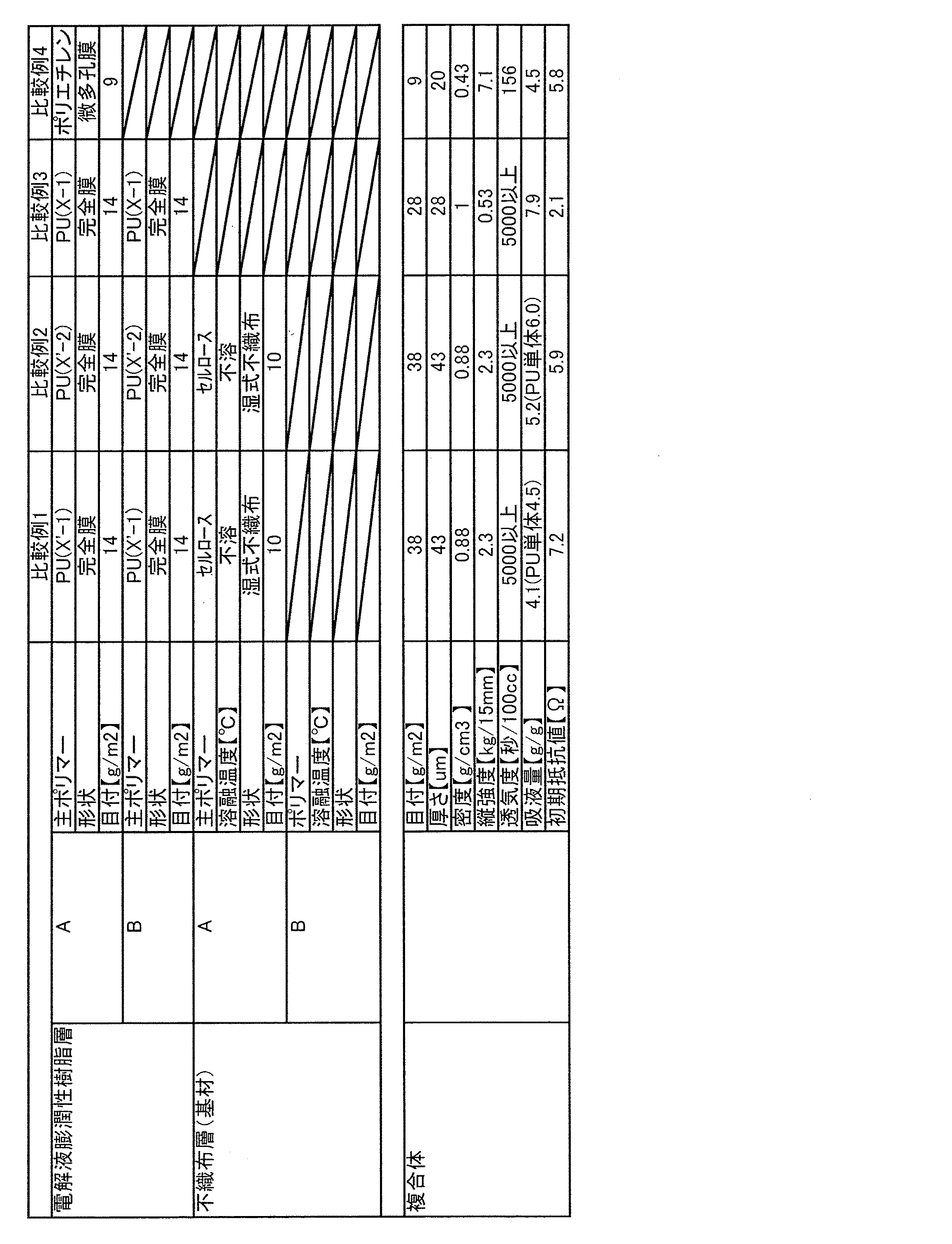
実施例1〜4のセパレータは、ウレタン樹脂の電解液に対する膨潤性が高いためいずれも初期抵抗が低く、高出力の非水系電池用セパレータとして申し分ない性質を示す。さらに、これらの実施例では、セパレータの強力も高く、製造時における取り扱い性に優れている。さらに、フッ化水素に対する耐性も高く、電解液の分解により発生するフッ化水素(HF)に対してもセパレータの重量は全く変化していない。 Since the separators of Examples 1 to 4 have high swellability with respect to the electrolyte solution of urethane resin, all of them have low initial resistance, and exhibit excellent properties as high-power non-aqueous battery separators. Furthermore, in these examples, the strength of the separator is high, and the handleability during manufacture is excellent. Furthermore, the resistance to hydrogen fluoride is high, and the weight of the separator does not change at all against hydrogen fluoride (HF) generated by the decomposition of the electrolytic solution.
低融点ポリマー層が存在する実施例4では、低融点ポリマーが異常発熱で溶融して皮膜を形成できるため、加熱後抵抗値が加熱前の抵抗値の8.2倍となり、良好なシャットダウン特性をも示している。 In Example 4 where the low melting point polymer layer exists, since the low melting point polymer can be melted by abnormal heat generation to form a film, the resistance value after heating becomes 8.2 times the resistance value before heating, and good shutdown characteristics are obtained. It also shows.
一方、比較例1のセパレータは、イオン伝導度が低いため、非水系電池のセパレータとしては使用できるものではない。 On the other hand, since the separator of Comparative Example 1 has low ionic conductivity, it cannot be used as a separator for non-aqueous batteries.
比較例2のセパレータは、イオン伝導度は有するものの、機械安定性が低下することから、非水系電池のセパレータとしては使用できるものではない。 Although the separator of Comparative Example 2 has ionic conductivity, it cannot be used as a separator for non-aqueous batteries because mechanical stability decreases.
比較例3のセパレータは、強力が低く、セパレータの損傷が発生しやすいため、加工性が悪く非水系電池のセパレータとしては使用できるものではない。 Since the separator of Comparative Example 3 has low strength and is likely to be damaged, the processability is poor and it cannot be used as a separator for non-aqueous batteries.
比較例4の微多孔フィルムでは初期抵抗が高いため、非水系電池のセパレータとして使用したときに電池の内部抵抗が高くなり、高出力が得られないばかりか、溶融によるシャットダウン特性はあるものの、異常発熱が進み、より高温となったときにシート形態を保っていないため極材同士が接触してさらに危険が増す場合があり、安全機能としては不十分なものとなる。 Since the microporous film of Comparative Example 4 has a high initial resistance, the internal resistance of the battery becomes high when used as a separator for a non-aqueous battery, and not only a high output cannot be obtained, but also there is a shutdown characteristic due to melting. Since the sheet form is not maintained when the heat generation proceeds and the temperature becomes higher, the pole materials may come into contact with each other to further increase the danger, which is insufficient as a safety function.
本発明の非水系電池用セパレータは、非水系電池に対して有用に利用することができる。 The separator for nonaqueous batteries of the present invention can be used effectively for nonaqueous batteries.
以上のとおり、本発明の好適な実施例を説明したが、当業者であれば、本件明細書を見て、自明な範囲内で種々の変更および修正を容易に想定するであろう。したがって、そのような変更および修正は、請求の範囲から定まる発明の範囲内のものと解釈される。 As described above, the preferred embodiments of the present invention have been described. However, those skilled in the art will readily understand various changes and modifications within the obvious scope by looking at the present specification. Accordingly, such changes and modifications are to be construed as within the scope of the invention as defined by the appended claims.
Claims (13)
ポリエーテルポリオール(a2)とを含有するポリオール(A)と、
ポリイソシアネート(B)とを反応させて得られるウレタン樹脂(C)よりなる電解液膨潤性樹脂層が、繊維集合体よりなる基材層の少なくとも片面に形成され、両者が一体化していることを特徴とする非水系電池用セパレータ。A vinyl polymer (a1 ′) having two hydroxyl groups at one end is used as a main chain, and a polyoxyethylene chain having a number average molecular weight of 200 to 800 is added to the side chain of the vinyl polymer (a1). A vinyl polymer (a1) having a number average molecular weight of 2000 to 7000 having a mass% to 98 mass%;
A polyol (A) containing a polyether polyol (a2);
The electrolyte-swellable resin layer made of urethane resin (C) obtained by reacting with polyisocyanate (B) is formed on at least one side of the base material layer made of fiber aggregate, and both are integrated. A non-aqueous battery separator.
前記シートまたはフィルムを繊維集合体よりなる支持基材の少なくとも片面に対して貼りあわせる工程と、
を含む非水系電池用セパレータの製造方法。A vinyl polymer (a1 ′) having two hydroxyl groups at one end is used as a main chain, and a polyoxyethylene chain having a number average molecular weight of 200 to 800 is added to the side chain of the vinyl polymer (a1). Obtained by reacting a polyol (A) containing a vinyl polymer (a1) having a number average molecular weight of 2000 to 7000 and a polyether polyol (a2), and a polyisocyanate (B). Producing a sheet or film from the urethane resin (C);
Bonding the sheet or film to at least one side of a support substrate made of a fiber assembly; and
The manufacturing method of the separator for non-aqueous batteries containing.
前記溶液または分散液を、繊維集合体よりなる支持基材に対して塗布または含浸する工程と、
を含む非水系電池用セパレータの製造方法。A vinyl polymer (a1 ′) having two hydroxyl groups at one end is used as a main chain, and a polyoxyethylene chain having a number average molecular weight of 200 to 800 is added to the side chain of the vinyl polymer (a1). Obtained by reacting a polyol (A) containing a vinyl polymer (a1) having a number average molecular weight of 2000 to 7000 and a polyether polyol (a2), and a polyisocyanate (B). Producing a solution or dispersion of urethane resin (C);
Applying or impregnating the solution or dispersion to a support substrate made of a fiber assembly;
The manufacturing method of the separator for non-aqueous batteries containing.
Priority Applications (1)
| Application Number | Priority Date | Filing Date | Title |
|---|---|---|---|
| JP2012540764A JP5771621B2 (en) | 2010-10-27 | 2011-10-13 | Non-aqueous battery separator, non-aqueous battery using the same, and method for producing non-aqueous battery separator |
Applications Claiming Priority (4)
| Application Number | Priority Date | Filing Date | Title |
|---|---|---|---|
| JP2010240329 | 2010-10-27 | ||
| JP2010240329 | 2010-10-27 | ||
| PCT/JP2011/073502 WO2012056890A1 (en) | 2010-10-27 | 2011-10-13 | Separator for non-aqueous batteries and non-aqueous battery equipped with same, and process for manufacturing separator for non-aqueous batteries |
| JP2012540764A JP5771621B2 (en) | 2010-10-27 | 2011-10-13 | Non-aqueous battery separator, non-aqueous battery using the same, and method for producing non-aqueous battery separator |
Publications (2)
| Publication Number | Publication Date |
|---|---|
| JPWO2012056890A1 JPWO2012056890A1 (en) | 2014-03-20 |
| JP5771621B2 true JP5771621B2 (en) | 2015-09-02 |
Family
ID=45993615
Family Applications (1)
| Application Number | Title | Priority Date | Filing Date |
|---|---|---|---|
| JP2012540764A Active JP5771621B2 (en) | 2010-10-27 | 2011-10-13 | Non-aqueous battery separator, non-aqueous battery using the same, and method for producing non-aqueous battery separator |
Country Status (6)
| Country | Link |
|---|---|
| US (1) | US9343721B2 (en) |
| EP (1) | EP2634838B1 (en) |
| JP (1) | JP5771621B2 (en) |
| KR (1) | KR101929063B1 (en) |
| CN (1) | CN103190016B (en) |
| WO (1) | WO2012056890A1 (en) |
Families Citing this family (16)
| Publication number | Priority date | Publication date | Assignee | Title |
|---|---|---|---|---|
| US8641273B2 (en) * | 2010-11-02 | 2014-02-04 | Sinoelectric Powertrain Corporation | Thermal interlock for battery pack, device, system and method |
| KR101256968B1 (en) * | 2012-10-25 | 2013-04-30 | 톱텍에이치앤에스 주식회사 | Pet non-woven fabric for separator of secondary battery and separator of secondary battery having the same |
| CN103855351A (en) * | 2014-03-11 | 2014-06-11 | 东莞新能源科技有限公司 | Lithium ion battery, isolation membrane utilized by same and preparation method of isolation membrane |
| JP6345514B2 (en) * | 2014-07-02 | 2018-06-20 | 旭化成株式会社 | Laminated microporous film and separator for lithium ion secondary battery |
| KR102221807B1 (en) * | 2014-08-11 | 2021-03-02 | 삼성에스디아이 주식회사 | Secondary battery |
| WO2016076992A1 (en) | 2014-11-10 | 2016-05-19 | Chemtura Corporation | Energy storage device comprising a polyureythane separator |
| US10186716B2 (en) | 2014-11-10 | 2019-01-22 | Lanxess Solutions Us Inc. | Non-aqueous flow cell comprising a polyurethane separator |
| EP3082186B1 (en) | 2015-04-14 | 2019-07-24 | Lanxess Solutions US Inc. | Non-aqueous flow cell comprising a polyurethane separator |
| US10573926B1 (en) | 2016-03-23 | 2020-02-25 | American Lithium Energy Corporation | Hybrid solid-state electrolyte |
| CN112366422A (en) * | 2016-03-29 | 2021-02-12 | 浙江地坤键新能源科技有限公司 | Non-porous diaphragm and application thereof |
| US10454142B2 (en) | 2016-05-31 | 2019-10-22 | American Lithium Energy Corporation | Enhanced solid state battery cell |
| CN106654127A (en) * | 2016-12-23 | 2017-05-10 | 合肥星源新能源材料有限公司 | High-wettability lithium-ion battery separator and preparation method thereof |
| PL3627586T3 (en) * | 2017-05-17 | 2022-11-07 | Teijin Limited | Separator for non-aqueous secondary batteries, non-aqueous secondary battery, and method for producing non-aqueous secondary battery |
| US10629861B2 (en) * | 2017-05-23 | 2020-04-21 | Samsung Electronics Co., Ltd. | Stretchable battery and method of manufacturing the same |
| KR102501467B1 (en) * | 2017-11-16 | 2023-02-20 | 삼성전자주식회사 | Composite separator, preparing method thereof, and secondary battery including the same |
| CN113140871B (en) * | 2021-03-26 | 2022-11-04 | 西安理工大学 | Diaphragm of self-supporting structure for lithium-sulfur battery and preparation method of diaphragm |
Citations (4)
| Publication number | Priority date | Publication date | Assignee | Title |
|---|---|---|---|---|
| JP2004055509A (en) * | 2001-09-27 | 2004-02-19 | Nisshinbo Ind Inc | Non-aqueous electrolyte secondary battery and power supply, portable equipment, and transportation or moving equipment, and home appliance using the secondary battery |
| JP2006019191A (en) * | 2004-07-02 | 2006-01-19 | Japan Vilene Co Ltd | Separator for lithium ion secondary battery, and lithium ion secondary battery |
| JP2009224100A (en) * | 2008-03-14 | 2009-10-01 | Toray Ind Inc | Separator for battery |
| JP2011046761A (en) * | 2009-08-25 | 2011-03-10 | Mitsubishi Paper Mills Ltd | Porous sheet, method for manufacturing the same, and separator for electrochemical element comprising the same |
Family Cites Families (8)
| Publication number | Priority date | Publication date | Assignee | Title |
|---|---|---|---|---|
| JPH05226002A (en) | 1991-02-25 | 1993-09-03 | Honda Motor Co Ltd | Lithium secondary cell gel-like electrolyte |
| JP2001351434A (en) * | 2000-06-07 | 2001-12-21 | Toyo Tire & Rubber Co Ltd | Gel electrolyte forming composition, gel electrolyte and manufacturing method |
| JP2003003078A (en) | 2000-09-19 | 2003-01-08 | Nisshinbo Ind Inc | Ion-conductive composition, gel elecrolyte, and non- aqueous electrolytic cell and electric double layer capacitor |
| TW579613B (en) | 2001-09-27 | 2004-03-11 | Nisshin Spinning | Nonaqueous electrolyte secondary cell, power supply comprising the secondary cell, portable device, transportable or movable machine, electric apparatus for home use, and method for charging nonaqueous electrolyte secondary cell |
| JP2004031084A (en) | 2002-06-25 | 2004-01-29 | Oji Paper Co Ltd | Separator for lithium ion secondary battery and battery using it |
| CN100415794C (en) * | 2003-07-24 | 2008-09-03 | 旭硝子株式会社 | Polyurethane resins and process for production thereof |
| JP5031606B2 (en) | 2008-01-30 | 2012-09-19 | ソニー株式会社 | Battery pack and manufacturing method thereof |
| JP5337550B2 (en) * | 2008-03-31 | 2013-11-06 | 日東電工株式会社 | Battery separator and battery using the same |
-
2011
- 2011-10-13 EP EP11836029.6A patent/EP2634838B1/en active Active
- 2011-10-13 CN CN201180051499.3A patent/CN103190016B/en active Active
- 2011-10-13 US US13/881,747 patent/US9343721B2/en active Active
- 2011-10-13 KR KR1020137013537A patent/KR101929063B1/en active IP Right Grant
- 2011-10-13 WO PCT/JP2011/073502 patent/WO2012056890A1/en active Application Filing
- 2011-10-13 JP JP2012540764A patent/JP5771621B2/en active Active
Patent Citations (4)
| Publication number | Priority date | Publication date | Assignee | Title |
|---|---|---|---|---|
| JP2004055509A (en) * | 2001-09-27 | 2004-02-19 | Nisshinbo Ind Inc | Non-aqueous electrolyte secondary battery and power supply, portable equipment, and transportation or moving equipment, and home appliance using the secondary battery |
| JP2006019191A (en) * | 2004-07-02 | 2006-01-19 | Japan Vilene Co Ltd | Separator for lithium ion secondary battery, and lithium ion secondary battery |
| JP2009224100A (en) * | 2008-03-14 | 2009-10-01 | Toray Ind Inc | Separator for battery |
| JP2011046761A (en) * | 2009-08-25 | 2011-03-10 | Mitsubishi Paper Mills Ltd | Porous sheet, method for manufacturing the same, and separator for electrochemical element comprising the same |
Also Published As
| Publication number | Publication date |
|---|---|
| US20130224557A1 (en) | 2013-08-29 |
| EP2634838B1 (en) | 2017-11-29 |
| CN103190016B (en) | 2015-05-20 |
| KR20140037794A (en) | 2014-03-27 |
| JPWO2012056890A1 (en) | 2014-03-20 |
| WO2012056890A1 (en) | 2012-05-03 |
| EP2634838A4 (en) | 2016-10-05 |
| KR101929063B1 (en) | 2018-12-13 |
| CN103190016A (en) | 2013-07-03 |
| EP2634838A1 (en) | 2013-09-04 |
| US9343721B2 (en) | 2016-05-17 |
Similar Documents
| Publication | Publication Date | Title |
|---|---|---|
| JP5771621B2 (en) | Non-aqueous battery separator, non-aqueous battery using the same, and method for producing non-aqueous battery separator | |
| JP5529148B2 (en) | Non-aqueous battery separator, non-aqueous battery using the same, and method for producing non-aqueous battery separator | |
| KR102190068B1 (en) | Polyolefin porous film, separator for batteries which is manufactured using said porous film, and methods respectively for manufacturing said porous film and said separator | |
| TWI479725B (en) | Separator and electrochemical device comprising the same | |
| JP4946006B2 (en) | Composite porous membrane and method for producing the same | |
| JP5189459B2 (en) | Lithium battery separator and lithium battery using the same | |
| JP5031835B2 (en) | Heat-resistant ultrafine fiber separation membrane and secondary battery using the same | |
| JP5424179B1 (en) | Battery separator and battery separator manufacturing method | |
| JP5870925B2 (en) | Composite porous membrane and method for producing the same | |
| US20100316912A1 (en) | Separator for power storage device | |
| KR20150141403A (en) | Complex fibrous separator, manufacturing method thereof and secondary battery using the same | |
| JP6166575B2 (en) | Electrode integrated separator and method for manufacturing the same | |
| JP3419393B2 (en) | Non-aqueous electrolyte secondary battery, separator and method of manufacturing the same | |
| JP6048753B2 (en) | Battery separator and battery separator manufacturing method | |
| JP2019197702A (en) | Non-woven fabric for battery separator and battery separator | |
| TWI549335B (en) | Separator of lithium ion battery and manufacturing method thereof, and lithium ion battery |
Legal Events
| Date | Code | Title | Description |
|---|---|---|---|
| A521 | Request for written amendment filed |
Free format text: JAPANESE INTERMEDIATE CODE: A523 Effective date: 20140825 |
|
| A621 | Written request for application examination |
Free format text: JAPANESE INTERMEDIATE CODE: A621 Effective date: 20140825 |
|
| TRDD | Decision of grant or rejection written | ||
| A01 | Written decision to grant a patent or to grant a registration (utility model) |
Free format text: JAPANESE INTERMEDIATE CODE: A01 Effective date: 20150616 |
|
| A61 | First payment of annual fees (during grant procedure) |
Free format text: JAPANESE INTERMEDIATE CODE: A61 Effective date: 20150629 |
|
| R150 | Certificate of patent or registration of utility model |
Ref document number: 5771621 Country of ref document: JP Free format text: JAPANESE INTERMEDIATE CODE: R150 |
|
| R250 | Receipt of annual fees |
Free format text: JAPANESE INTERMEDIATE CODE: R250 |
|
| S533 | Written request for registration of change of name |
Free format text: JAPANESE INTERMEDIATE CODE: R313533 |
|
| R350 | Written notification of registration of transfer |
Free format text: JAPANESE INTERMEDIATE CODE: R350 |
|
| R250 | Receipt of annual fees |
Free format text: JAPANESE INTERMEDIATE CODE: R250 |
|
| R250 | Receipt of annual fees |
Free format text: JAPANESE INTERMEDIATE CODE: R250 |
|
| R250 | Receipt of annual fees |
Free format text: JAPANESE INTERMEDIATE CODE: R250 |
|
| R250 | Receipt of annual fees |
Free format text: JAPANESE INTERMEDIATE CODE: R250 |
|
| R250 | Receipt of annual fees |
Free format text: JAPANESE INTERMEDIATE CODE: R250 |