JP5771428B2 - Disc brake - Google Patents

Disc brake Download PDF

Info

Publication number
JP5771428B2
JP5771428B2 JP2011077026A JP2011077026A JP5771428B2 JP 5771428 B2 JP5771428 B2 JP 5771428B2 JP 2011077026 A JP2011077026 A JP 2011077026A JP 2011077026 A JP2011077026 A JP 2011077026A JP 5771428 B2 JP5771428 B2 JP 5771428B2
Authority
JP
Japan
Prior art keywords
disk
disc
disc brake
bore
cylinder portion
Prior art date
Legal status (The legal status is an assumption and is not a legal conclusion. Google has not performed a legal analysis and makes no representation as to the accuracy of the status listed.)
Active
Application number
JP2011077026A
Other languages
Japanese (ja)
Other versions
JP2012211626A5 (en
JP2012211626A (en
Inventor
南里 圭介
圭介 南里
公靖 高野
公靖 高野
Current Assignee (The listed assignees may be inaccurate. Google has not performed a legal analysis and makes no representation or warranty as to the accuracy of the list.)
Hitachi Astemo Ltd
Original Assignee
Hitachi Automotive Systems Ltd
Priority date (The priority date is an assumption and is not a legal conclusion. Google has not performed a legal analysis and makes no representation as to the accuracy of the date listed.)
Filing date
Publication date
Application filed by Hitachi Automotive Systems Ltd filed Critical Hitachi Automotive Systems Ltd
Priority to JP2011077026A priority Critical patent/JP5771428B2/en
Publication of JP2012211626A publication Critical patent/JP2012211626A/en
Publication of JP2012211626A5 publication Critical patent/JP2012211626A5/ja
Application granted granted Critical
Publication of JP5771428B2 publication Critical patent/JP5771428B2/en
Active legal-status Critical Current
Anticipated expiration legal-status Critical

Links

Images

Description

本発明は、自動二輪車や四輪自動車等の車両を制動するためのディスクブレーキに関する。   The present invention relates to a disc brake for braking a vehicle such as a motorcycle or a four-wheeled vehicle.

ディスクブレーキにおいて、取付孔を有する車体への取り付け用のボス部を、軽量化のため部分的に円筒状をなす形状に形成したものがある(例えば、特許文献1参照)。   In some disc brakes, a boss portion for attachment to a vehicle body having an attachment hole is formed in a partially cylindrical shape for weight reduction (see, for example, Patent Document 1).

特開2011−12719号公報JP 2011-12719 A

しかしながら、上記のディスクブレーキにおいては、ボアの底部の熱が逃げにくく、性能低下の要因となることがあった。   However, in the above-described disc brake, the heat at the bottom of the bore is difficult to escape, which may cause performance degradation.

本発明は、熱による性能低下を抑制することができるディスクブレーキの提供を目的とする。   An object of this invention is to provide the disc brake which can suppress the performance fall by heat.

上記目的を達成するために、本発明は、部分的円筒状部に、シリンダ部のディスク周方向端部からディスク半径方向内方へ突出する内方突出部が形成され、前記シリンダ部のディスク半径方向内側の面からディスク半径方向の内方へ突出して立設される伝熱部が、前記シリンダ部におけるボアの底部と前記内方突出部とを結んでいるIn order to achieve the above object, according to the present invention, an inward protruding portion that protrudes inward in the disk radial direction from a disk circumferential end of the cylinder portion is formed in the partial cylindrical portion, and the disk radius of the cylinder portion is increased. heat transfer portion which is erected protruding from inward face inward of the disk radial direction, it has signed with the inwardly projecting portion and the bottom portion of the bore in the cylinder portion.

請求項1に係る発明によれば、熱による性能低下を抑制することができる。   According to the first aspect of the present invention, it is possible to suppress performance degradation due to heat.

本発明に係る一実施形態のディスクブレーキを示す正面図である。It is a front view showing a disc brake of one embodiment concerning the present invention. 本発明に係る一実施形態のディスクブレーキを示す側面図である。1 is a side view showing a disc brake according to an embodiment of the present invention. 本発明に係る一実施形態のディスクブレーキを示す下面図である。It is a bottom view showing a disc brake of one embodiment concerning the present invention. 本発明に係る一実施形態のディスクブレーキを示す斜視図である。It is a perspective view showing a disc brake of one embodiment concerning the present invention. 本発明に係る一実施形態のディスクブレーキを示す斜視図である。It is a perspective view showing a disc brake of one embodiment concerning the present invention. 本発明に係る一実施形態のディスクブレーキを示す図1のX−X断面図である。It is XX sectional drawing of FIG. 1 which shows the disc brake of one Embodiment which concerns on this invention.

本発明に係る一実施形態のディスクブレーキを図面に基づいて説明する。   A disc brake according to an embodiment of the present invention will be described with reference to the drawings.

本実施形態のディスクブレーキ1は、自動二輪車の前輪制動用のディスクブレーキである。なお、これに限らず、例えば自動二輪車の後輪制動用や四輪自動車の制動用のディスクブレーキにも勿論適用可能である。   The disc brake 1 of this embodiment is a disc brake for braking the front wheels of a motorcycle. Of course, the present invention is not limited to this, and can be applied to a disc brake for braking a rear wheel of a motorcycle or a brake of a four-wheeled vehicle.

このディスクブレーキ10は、図1〜図3に示すように、制動対象となる車輪とともに回転するディスク11と、このディスク11に摩擦抵抗を付与するキャリパ12とを備えている。なお、以下においては、車両への取付状態をもって説明し、この取付状態におけるディスク11の円周方向(回転方向)をディスク周方向と称し、ディスク周方向のキャリパ12の中央位置を通りディスク11の半径方向に沿う方向をディスク半径方向と称し、ディスク11の回転軸線方向をディスク軸方向と称す。   As shown in FIGS. 1 to 3, the disc brake 10 includes a disc 11 that rotates with a wheel to be braked, and a caliper 12 that imparts friction resistance to the disc 11. In the following, description will be given with the state of attachment to the vehicle, the circumferential direction (rotation direction) of the disk 11 in this attachment state is referred to as the disk circumferential direction, and the disk 11 passes through the center position of the caliper 12 in the disk circumferential direction. A direction along the radial direction is referred to as a disk radial direction, and a rotation axis direction of the disk 11 is referred to as a disk axis direction.

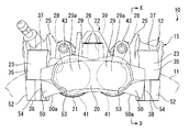
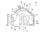
キャリパ12は、ディスク11を外径側にて跨いだ状態で車両の非回転部に取り付けられるキャリパ本体15を有している。キャリパ本体15は、図1に示すように、ディスク周方向に沿って長い形状をなすとともにディスク11のアウタ側(車輪に対し反対側)に配置されるシリンダ部20と、ディスク周方向に沿って長い形状をなすとともに図3に示すようにディスク11のインナ側(車輪側)に配置されるシリンダ部21と、図2に示すように、シリンダ部20およびシリンダ部21のそれぞれのディスク径方向外側からディスク11の外周側へ延びてシリンダ部20とシリンダ部21とをディスク11の径方向外側で結ぶブリッジ部22と、図3に示すように、アウタ側のシリンダ部20のディスク軸方向の中間位置にてディスク周方向両側に設けられる車体への取り付け用の一対のボス部23,23とを有している。キャリパ本体15は、これらシリンダ部20,21、ブリッジ部22およびボス部23,23が一体的に鋳造により形成された、いわゆるモノブロックタイプとなっている。   The caliper 12 has a caliper body 15 that is attached to a non-rotating portion of the vehicle in a state where the disk 11 is straddled on the outer diameter side. As shown in FIG. 1, the caliper body 15 has a long shape along the circumferential direction of the disk and a cylinder portion 20 disposed on the outer side of the disk 11 (the side opposite to the wheel), along the circumferential direction of the disk. The cylinder part 21 which is long and is disposed on the inner side (wheel side) of the disk 11 as shown in FIG. 3, and the outer side in the disk radial direction of each of the cylinder part 20 and the cylinder part 21 as shown in FIG. 3 to the outer peripheral side of the disk 11 to connect the cylinder part 20 and the cylinder part 21 on the outer side in the radial direction of the disk 11, and as shown in FIG. 3, the intermediate part of the outer side cylinder part 20 in the disk axial direction. It has a pair of boss portions 23, 23 for attachment to the vehicle body provided on both sides in the circumferential direction of the disc at the position. The caliper body 15 is a so-called monoblock type in which the cylinder portions 20 and 21, the bridge portion 22, and the boss portions 23 and 23 are integrally formed by casting.

上記したブリッジ部22は、図1に示すように、ディスク周方向両側に配置される一対のブリッジ構成部25,25と、ディスク周方向におけるこれらの間位置に配置されるブリッジ構成部26とからなっている。その結果、ブリッジ部22には、ディスク周方向一側のブリッジ構成部25とブリッジ構成部26との間と、ディスク周方向他側のブリッジ構成部25とブリッジ構成部26との間とに、それぞれ、ディスク径方向に貫通する図示略の開口部が形成されている。   As shown in FIG. 1, the above-described bridge portion 22 includes a pair of bridge constituent portions 25 and 25 disposed on both sides of the disk circumferential direction, and a bridge constituent portion 26 disposed between these in the disk circumferential direction. It has become. As a result, the bridge portion 22 includes a bridge configuration portion 25 and a bridge configuration portion 26 on one side in the disk circumferential direction, and a bridge configuration portion 25 and a bridge configuration portion 26 on the other side in the disk circumferential direction. Each has an opening (not shown) penetrating in the disk radial direction.

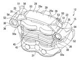
アウタ側のシリンダ部20には、ディスク周方向一側のブリッジ構成部25と中央のブリッジ構成部26との間位置と、ディスク周方向他側のブリッジ構成部25とブリッジ構成部26との間位置とに、それぞれ、ディスク軸方向に沿うボア28が、図3に示すようにディスク11に対向して開口するように形成されている。シリンダ部20が有するこれらのボア28,28は、ディスク11とは反対側の底部29,29の外面29a,29aが連続する同一面に配置されてキャリパ本体15におけるディスク軸方向のアウタ側の外面を構成している。なお、ボア28,28の内周面28a,28aはディスク軸方向に直交する断面が円形状をなしており、ボア28,28の内底面28b,28bはディスク軸方向に直交している。   The cylinder portion 20 on the outer side has a position between the bridge constituent portion 25 on the one side in the disk circumferential direction and the bridge constituent portion 26 on the central side, and between the bridge constituent portion 25 on the other side in the disc circumferential direction and the bridge constituent portion 26. In each position, a bore 28 along the disk axial direction is formed so as to open facing the disk 11 as shown in FIG. These bores 28, 28 of the cylinder portion 20 are arranged on the same surface where the outer surfaces 29a, 29a of the bottom portions 29, 29 on the opposite side of the disc 11 are continuous, and the outer surface of the caliper body 15 on the outer side in the disc axial direction. Is configured. The inner peripheral surfaces 28a and 28a of the bores 28 and 28 have a circular cross section perpendicular to the disk axis direction, and the inner bottom surfaces 28b and 28b of the bores 28 and 28 are orthogonal to the disk axis direction.

インナ側のシリンダ部21には、ボア28,28のそれぞれと対向するように、ディスク軸方向に沿うボア31が形成されている。これらのボア31,31は、ディスク11とは反対側の底部32,32の外面32a,32aがキャリパ本体15におけるディスク軸方向のインナ側の外面を構成している。なお、ボア31,31の内周面31a,31aはディスク軸方向に直交する断面が円形状をなしており、ボア31,31の内底面31b,31bはディスク軸方向に直交している。   A bore 31 along the disk axial direction is formed in the inner cylinder portion 21 so as to face each of the bores 28 and 28. In these bores 31, 31, the outer surfaces 32 a, 32 a of the bottom portions 32, 32 on the side opposite to the disk 11 constitute an outer surface on the inner side of the caliper body 15 in the disk axial direction. The inner peripheral surfaces 31a and 31a of the bores 31 and 31 have a circular cross section orthogonal to the disk axis direction, and the inner bottom surfaces 31b and 31b of the bores 31 and 31 are orthogonal to the disk axis direction.

なお、インナ側のシリンダ部21のボア31,31の底部32,32には、図示は略すが、アウタ側のボア28,28内およびインナ側のボア31,31内を切削加工のための工具が挿通される底部貫通穴が形成されている。この底部貫通穴が、別体の蓋部材を摩擦攪拌接合することで閉塞され、その結果、底部32,32が形成されている。これに対し、アウタ側のシリンダ部20のボア28,28の底部29,29は、キャリパ本体15の鋳造時に成形されている。   Although not shown, the bottoms 32 and 32 of the bores 31 and 31 of the inner cylinder portion 21 are tools for cutting in the outer bores 28 and 28 and the inner bores 31 and 31. A bottom through hole is formed through which is inserted. The bottom through-hole is closed by friction stir welding of a separate lid member, and as a result, bottom portions 32 and 32 are formed. On the other hand, the bottom portions 29 and 29 of the bores 28 and 28 of the outer cylinder portion 20 are formed when the caliper body 15 is cast.

ディスク周方向の同側に配置されるボア28,31同士は、同径であって同心つまり同一直線上に並べられて対をなしており、このようなボア28,31の対が、ディスク周方向に離間して二対形成されている。ここで、ディスク周方向の一側で対をなすボア28,31の径は、ディスク周方向の他側で対をなすボア28,31の径よりも若干大径となっている。なお、対向配置されるボア28,31の対は、少なくとも一対あれば良く、三対以上あっても良い。   The bores 28 and 31 arranged on the same side in the circumferential direction of the disk have the same diameter and are arranged concentrically, that is, aligned on the same straight line to form a pair. Two pairs are formed apart in the direction. Here, the diameters of the bores 28 and 31 paired on one side of the disk circumferential direction are slightly larger than the diameters of the bores 28 and 31 paired on the other side of the disk circumferential direction. It should be noted that at least one pair of the bores 28 and 31 disposed to face each other is sufficient, and there may be three or more pairs.

アウタ側の両側のボス部23,23には、軽量化のため部分的に略円筒形をなす部分的円筒状部35,35が形成されている。部分的円筒状部35,35は、それぞれの内部の中央にディスク半径方向に沿って貫通する取付孔36を有している。部分的円筒状部35,35は、それぞれのディスク半径方向の外端部が、取付孔36に挿通される図示略の取付ボルトの図1に示す座部37となり、それぞれのディスク半径方向の内端部が車体側に接合される接合部38となる。つまり、キャリパ12は、図3に示す取付孔36,36に挿通される図示略の取付ボルトで車体側(具体的にはフロントフォーク)に固定される、いわゆるラジアルマウントタイプとなっている。言い換えれば、キャリパ12は、ボス部23,23の部分的円筒状部35,35において取付ボルトの軸力を受ける。   The boss portions 23, 23 on both sides on the outer side are formed with partially cylindrical portions 35, 35 that are partially cylindrical in order to reduce weight. The partial cylindrical portions 35 and 35 each have a mounting hole 36 penetrating along the radial direction of the disk in the center of the inside thereof. In the partial cylindrical portions 35, 35, the outer end portions in the disk radial direction become the seat portions 37 shown in FIG. 1 of mounting bolts (not shown) inserted through the mounting holes 36, and the inner portions in the respective disk radial directions. The end portion becomes a joint portion 38 joined to the vehicle body side. In other words, the caliper 12 is a so-called radial mount type that is fixed to the vehicle body side (specifically, the front fork) with a mounting bolt (not shown) inserted through the mounting holes 36, 36 shown in FIG. In other words, the caliper 12 receives the axial force of the mounting bolt at the partial cylindrical portions 35 and 35 of the boss portions 23 and 23.

また、アウタ側のシリンダ部20には、ディスク周方向の中央位置に、図1に示す連通路39がディスク半径方向に沿って穿設されている。この連通路39には、シリンダ部20およびシリンダ部21内にブレーキ液を給排するための図示略のブレーキホースが接続される。   Further, a communication passage 39 shown in FIG. 1 is formed in the outer cylinder portion 20 along the disk radial direction at a central position in the disk circumferential direction. A brake hose (not shown) for supplying and discharging brake fluid into and from the cylinder part 20 and the cylinder part 21 is connected to the communication path 39.

図3に示すように、アウタ側のボア28,28およびインナ側のボア31,31には、それぞれピストン41が摺動可能に配置されている。よってディスク11の両側で同一直線上に配置されて対をなすピストン41,41が、ディスク周方向に所定の間隔をあけて二対設けられている。つまり、キャリパ本体15とピストン41,41,…とを備えるキャリパ12は、対向ピストン型の4ポットキャリパとなっている。なお、ディスク周方向の一側で対をなすピストン41,41の径も、ディスク周方向の他側で対をなすピストン41,41の径より若干大径となっている。   As shown in FIG. 3, pistons 41 are slidably disposed in the outer-side bores 28 and 28 and the inner-side bores 31 and 31, respectively. Therefore, two pairs of pistons 41, 41 arranged on the same straight line on both sides of the disk 11 and having a predetermined interval in the circumferential direction of the disk are provided. That is, the caliper 12 including the caliper main body 15 and the pistons 41, 41,... Is an opposed piston type four-pot caliper. The diameters of the pistons 41 and 41 paired on one side of the disk circumferential direction are also slightly larger than the diameters of the pistons 41 and 41 paired on the other side of the disk circumferential direction.

図1に示すように、キャリパ本体15には、ディスク軸方向に沿ってシリンダ部20およびシリンダ部21間に橋架される二本のパッドピン43,43がディスク周方向に離間して設けられている。一方のパッドピン43は、一方のブリッジ構成部25とブリッジ構成部26との間に、他方のパッドピン43は、他方のブリッジ構成部25とブリッジ構成部26との間に、それぞれ設けられている。   As shown in FIG. 1, the caliper body 15 is provided with two pad pins 43, 43 that are bridged between the cylinder portion 20 and the cylinder portion 21 along the disc axial direction so as to be separated in the disc circumferential direction. . One pad pin 43 is provided between one bridge component 25 and the bridge component 26, and the other pad pin 43 is provided between the other bridge component 25 and the bridge component 26.

これらのパッドピン43には、ディスク11の両側に配置される図2および図3に示す一対のブレーキパッド45,45が、ディスク軸方向に移動可能となるように支持されている。これらブレーキパッド45,45のそれぞれのディスク11とは反対側には、図3に示すように上記したピストン41,41,…が配置されており、これらピストン41,41,…が、図1に示す連通路39を介して図3に示すボア28,28,31,31内に導入されるブレーキ液圧によってボア28,28,31,31内で摺動してディスク11の方向に移動する。これにより、ピストン41,41,…とディスク11との間に設けられたブレーキパッド45,45がディスク11に押し付けられ、車両に制動力を発生させる。なお、ブレーキパッド45,45の対は、少なくとも一対設けられていれば良く、例えばピストン41と一対一で対応するように複数対設けても良い。   A pair of brake pads 45 and 45 shown in FIGS. 2 and 3 disposed on both sides of the disk 11 are supported by these pad pins 43 so as to be movable in the disk axial direction. As shown in FIG. 3, the above-described pistons 41, 41,... Are arranged on the opposite sides of the brake pads 45, 45 from the disk 11, and these pistons 41, 41,. 3 slides in the bores 28, 28, 31, 31 and moves in the direction of the disk 11 by the brake fluid pressure introduced into the bores 28, 28, 31, 31 shown in FIG. As a result, brake pads 45, 45 provided between the pistons 41, 41,... And the disk 11 are pressed against the disk 11 to generate a braking force on the vehicle. Note that at least one pair of brake pads 45 and 45 may be provided. For example, a plurality of pairs may be provided so as to correspond one-to-one with the piston 41.

そして、本実施形態においては、ボス部23,23が有する上記した部分的円筒状部35,35とシリンダ部20のボア28,28の底部29,29との、近接するもの同士を結んで、シリンダ部20よりもディスク半径方向内方に突出するように、図1〜図6に示すリブ状の伝熱部50,50が立設されている。   In the present embodiment, the above-described partial cylindrical portions 35 and 35 of the boss portions 23 and 23 and the bottom portions 29 and 29 of the bores 28 and 28 of the cylinder portion 20 are connected to each other, Rib-shaped heat transfer portions 50 and 50 shown in FIGS. 1 to 6 are erected so as to protrude inward in the disk radial direction from the cylinder portion 20.

ディスク周方向一側のボア28、ボス部23および伝熱部50と、ディスク周方向他側のボア28、ボス部23および伝熱部50とは、ボア28の径が若干異なることに伴う部分以外は共通の略鏡面対称の形状をなしているため、以下、ディスク周方向一側のボア28、ボス部23および伝熱部50を例にとり、さらに説明する。   The bore 28, the boss 23, and the heat transfer portion 50 on one side in the circumferential direction of the disk and the bore 28, the boss portion 23, and the heat transfer portion 50 on the other side in the circumferential direction of the disk are portions associated with slightly different diameters of the bore 28 Other than the above, since they have a common substantially mirror-symmetric shape, the bore 28, the boss portion 23, and the heat transfer portion 50 on one side in the disk circumferential direction will be further described below as an example.

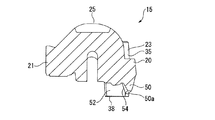
部分的円筒状部35は、図4および図5に示すように、ボス部23のディスク半径方向の全長にわたって形成されている。部分的円筒状部35は、図3に示すように、アウタ側のシリンダ部20よりも、ディスク軸方向においてディスク11とは反対側に突出しており、これにより、シリンダ部20とで互いの境界位置近傍にディスク半径方向内方から見て凹む凹状部51を形成する。また、部分的円筒状部35は、アウタ側のシリンダ部20よりも、ディスク回転軸線と直交する方向であるディスク周方向のボア28とは反対側に突出しており、図4および図5に示すように、ディスク回転軸線と直交する方向であるディスク半径方向内方にも突出している。部分的円筒状部35のこのシリンダ部20からディスク半径方向内方へ突出する内方突出部52の突出先端が、上記した車体側への接合部38となる。内方突出部52は、接合部38側の部分が全周にわたって連続する略円筒状をなしている。   As shown in FIGS. 4 and 5, the partial cylindrical portion 35 is formed over the entire length of the boss portion 23 in the disk radial direction. As shown in FIG. 3, the partial cylindrical portion 35 protrudes on the side opposite to the disc 11 in the disc axial direction from the outer side cylinder portion 20, and thereby the boundary between the cylinder portion 20 and each other. A recessed portion 51 that is recessed when viewed from the inner side in the disk radial direction is formed in the vicinity of the position. Further, the partial cylindrical portion 35 protrudes on the opposite side of the outer circumferential side cylinder portion 20 from the disk circumferential bore 28 which is a direction orthogonal to the disk rotation axis, as shown in FIGS. 4 and 5. Thus, it also protrudes inward in the disk radial direction, which is a direction orthogonal to the disk rotation axis. The protruding tip of the inward protruding portion 52 that protrudes inward in the radial direction of the disk from the cylinder portion 20 of the partial cylindrical portion 35 is the above-described joint portion 38 to the vehicle body side. The inward projecting portion 52 has a substantially cylindrical shape in which a portion on the joint portion 38 side is continuous over the entire circumference.

図3に示すように、伝熱部50は、底部29への連結部53よりも部分的円筒状部35への連結部54の方が、ディスク軸方向においてディスク11側に位置するように傾斜しており、連結部54は部分的円筒状部35の内方突出部52に連結されている。連結部54は、その全体が、ディスク軸方向において、内方突出部52と位置が重なり合っており、取付孔36の中心よりもディスク11とは反対側の範囲に配置されている。言い換えれば、伝熱部50の連結部54は、その全体がディスク軸方向において、内方突出部52のディスク11とは反対側の端部からディスク11側に、取付孔36の中心までの範囲内で配置されている。   As shown in FIG. 3, the heat transfer portion 50 is inclined so that the connecting portion 54 to the partial cylindrical portion 35 is located on the disc 11 side in the disc axial direction rather than the connecting portion 53 to the bottom portion 29. The connecting portion 54 is connected to the inward protruding portion 52 of the partial cylindrical portion 35. The entire connecting portion 54 overlaps with the inward projecting portion 52 in the disc axial direction, and is disposed in a range on the opposite side of the disc 11 from the center of the mounting hole 36. In other words, the entire connecting portion 54 of the heat transfer portion 50 extends in the disc axial direction from the end of the inward projecting portion 52 opposite to the disc 11 to the disc 11 side to the center of the mounting hole 36. Are arranged within.

また、伝熱部50の連結部54は、その全体が、ディスク周方向においても、内方突出部52と位置が重なり合っており、取付孔36の中心よりもディスク周方向のボア28側の範囲に配置されている。言い換えれば、伝熱部50の連結部54は、ディスク周方向において、内方突出部52のボア28側の端部からボア31とは反対側に、取付孔36の中心までの範囲内で配置されている。   Further, the entire connecting portion 54 of the heat transfer portion 50 overlaps the position of the inward protruding portion 52 also in the disk circumferential direction, and the range on the bore 28 side in the disk circumferential direction from the center of the mounting hole 36. Is arranged. In other words, the connecting portion 54 of the heat transfer portion 50 is disposed within the range from the end on the bore 28 side of the inward protruding portion 52 to the center of the mounting hole 36 on the side opposite to the bore 31 in the disk circumferential direction. Has been.

伝熱部50は、図6に示すように、ディスク半径方向の内方ほど厚さが薄くなる形状をなしており、そのディスク半径方向内側の端面50aが、最も薄く、伝熱部50の厚さ方向の最も中央側に位置している。   As shown in FIG. 6, the heat transfer section 50 has a shape in which the thickness decreases toward the inner side in the disk radial direction, and the end surface 50 a on the inner side in the disk radial direction is the thinnest, and the thickness of the heat transfer section 50 is It is located on the most central side in the vertical direction.

以上に述べた本実施形態のディスクブレーキ10によれば、制動時にディスク11とブレーキパッド45,45とに摩擦熱が生じることになり、この摩擦熱のうち主にアウタ側のブレーキパッド45に生じる摩擦熱が、このブレーキパッド45からアウタ側のピストン41,41およびブレーキ液を介してアウタ側のシリンダ部20のボア28,28に伝わることになるが、この熱を、ボア28,28の底部29,29側から伝熱部50,50によって良好にボス部23,23の部分的円筒状部35,35に伝達し、接合部38,38から車体側に逃がすことができる。よって、キャリパ12の放熱性能を向上させることができ、熱による性能低下、特にボア28,28の底部29,29の温度上昇による動的性能の低下を抑制することができる。また、ボア28,28内のブレーキ液の温度を低下させることができるため、ベーパーロックの発生を抑制できる。加えて、ボア28,28の温度と、ボア28,28およびピストン41,41の間の図示略のシールの温度とを低下させることができるため、熱間時のブレーキレバーの操作フィーリングを向上させることができ、ブレーキ液の漏れに対する信頼性を向上できる。さらに、ブレーキパッド45,45の温度も低下させることができるため、フェードの発生を抑制し、反りを低減できる。   According to the disc brake 10 of the present embodiment described above, frictional heat is generated between the disc 11 and the brake pads 45 and 45 during braking, and the frictional heat is mainly generated in the brake pad 45 on the outer side. The frictional heat is transmitted from the brake pad 45 to the bores 28 and 28 of the outer cylinder portion 20 via the outer pistons 41 and 41 and the brake fluid. This heat is transferred to the bottom of the bores 28 and 28. The heat transfer portions 50 and 50 can be favorably transmitted from the 29 and 29 sides to the partial cylindrical portions 35 and 35 of the boss portions 23 and 23 and can be released from the joint portions 38 and 38 to the vehicle body side. Therefore, the heat dissipation performance of the caliper 12 can be improved, and the performance degradation due to heat, in particular, the dynamic performance degradation due to the temperature rise of the bottom portions 29 and 29 of the bores 28 and 28 can be suppressed. Moreover, since the temperature of the brake fluid in the bores 28 and 28 can be lowered, the occurrence of vapor lock can be suppressed. In addition, since the temperature of the bores 28 and 28 and the temperature of a seal (not shown) between the bores 28 and 28 and the pistons 41 and 41 can be lowered, the operation feeling of the brake lever when hot is improved. It is possible to improve the reliability against leakage of brake fluid. Furthermore, since the temperature of the brake pads 45 can be lowered, the occurrence of fade can be suppressed and the warpage can be reduced.

加えて、ディスク円周方向に対し傾斜する伝熱部50がシリンダ部20の外側の走行風をシリンダ部20のディスク11側およびボス部23側に導風するため、キャリパ12の全体の冷却効率を向上できる。また、これによりボス部23自体の温度を低下させることができるため、取付ボルトの軸力の安定化を図ることができ、ボス部23の変形を抑制できる。   In addition, since the heat transfer section 50 inclined with respect to the circumferential direction of the disk guides the traveling air outside the cylinder section 20 to the disk 11 side and the boss section 23 side of the cylinder section 20, the overall cooling efficiency of the caliper 12 Can be improved. Moreover, since the temperature of the boss | hub part 23 itself can be lowered | hung by this, the axial force of a mounting bolt can be stabilized and the deformation | transformation of the boss | hub part 23 can be suppressed.

10 ディスクブレーキ
11 ディスク
20 シリンダ部
23 ボス部
28 ボア
29 底部
35 部分的円筒状部
36 取付孔
41 ピストン
45 ブレーキパッド
50 伝熱部
DESCRIPTION OF SYMBOLS 10 Disc brake 11 Disc 20 Cylinder part 23 Boss part 28 Bore 29 Bottom part 35 Partial cylindrical part 36 Mounting hole 41 Piston 45 Brake pad 50 Heat-transfer part

Claims (4)

ディスクの両側に配置される少なくとも一対のブレーキパッドと、
前記ディスクの両側に配置されて前記一対のブレーキパッドを前記ディスクに押圧する少なくとも一対のピストンと、
前記ピストンが摺動するボアを有し、ディスク周方向に沿って長い形状をなすシリンダ部と、
該シリンダ部のディスク周方向両側に設けられ、内部に取付孔を有しディスク回転軸線と直交する方向に沿って突出する部分的円筒状部を有するボス部と、を備えたディスクブレーキにおいて、
前記部分的円筒状部には、前記シリンダ部のディスク周方向端部からディスク半径方向内方へ突出する内方突出部が形成され、
前記シリンダ部のディスク半径方向内側の面からディスク半径方向内方へ突出して立設される伝熱部が、前記シリンダ部における前記ボアの底部と前記内方突出部とを結んで形成されていることを特徴とするディスクブレーキ。
At least a pair of brake pads disposed on both sides of the disc;
At least a pair of pistons disposed on both sides of the disk to press the pair of brake pads against the disk;
Have a bore in which the piston slides, the cylinder portion forming a long shape along the circumferential direction of the disk,
Provided in the disk circumferential direction on both sides of the cylinder portion, in a disc brake and a boss portion having a partially cylindrical portion projecting along a direction perpendicular to the disk axis of rotation have a inside the mounting hole,
The partial cylindrical portion is formed with an inward protruding portion that protrudes inward in the radial direction of the disc from the circumferential end of the cylinder portion.
From the disk radially inner surface protrudes into the disc radially inwardly heat transfer portion which is erected of the cylinder portion, it is made form by connecting the bottom of the bore in the cylinder portion and the inward protrusion Disc brakes characterized by
前記部分的円筒状部と前記シリンダ部との境界位置近傍には、前記内方突出部と前記シリンダ部と前記伝熱部とによってディスク半径方向内方から見て凹んで形成される凹状部を有することを特徴とする請求項1に記載のディスクブレーキ。In the vicinity of the boundary position between the partial cylindrical portion and the cylinder portion, there is a concave portion formed by the inner projecting portion, the cylinder portion, and the heat transfer portion as seen from the inner side in the disk radial direction. The disc brake according to claim 1, wherein the disc brake is provided. 前記伝熱部は、前記ボアの底部に連結する第1の連結部と前記部分的円筒状部に連結す第2の連結部とを有し、ディスク回転軸線方向において前記第1の連結部よりも前記第2の連結部の方がディスク側に位置するように傾斜して配置されていることを特徴とする請求項1または2に記載のディスクブレーキ。 The heat transfer section, and a first second connecting portion and the connecting portion you connected to said partially cylindrical portion of the coupling to the bottom of the bore, the first connecting portion in the disk rotational axis 3. The disc brake according to claim 1, wherein the second connecting portion is inclined and disposed so as to be positioned on the disc side. 前記伝熱部は、前記ボアの底部に連結する第1の連結部と前記部分的円筒状部に連結する第2の連結部とを有し、前記第2の連結部がディスク回転軸線方向において前記取付孔の中心よりもディスクとは反対側の範囲に配置されていることを特徴とする請求項1乃至3のいずれか一項に記載のディスクブレーキ。 The heat transfer part has a first connection part connected to the bottom part of the bore and a second connection part connected to the partial cylindrical part, and the second connection part is in the disc rotation axis direction. The disc brake according to any one of claims 1 to 3, wherein the disc brake is disposed in a range on the opposite side of the disc from the center of the mounting hole.
JP2011077026A 2011-03-31 2011-03-31 Disc brake Active JP5771428B2 (en)

Priority Applications (1)

Application Number Priority Date Filing Date Title
JP2011077026A JP5771428B2 (en) 2011-03-31 2011-03-31 Disc brake

Applications Claiming Priority (1)

Application Number Priority Date Filing Date Title
JP2011077026A JP5771428B2 (en) 2011-03-31 2011-03-31 Disc brake

Publications (3)

Publication Number Publication Date
JP2012211626A JP2012211626A (en) 2012-11-01
JP2012211626A5 JP2012211626A5 (en) 2014-03-06
JP5771428B2 true JP5771428B2 (en) 2015-08-26

Family

ID=47265753

Family Applications (1)

Application Number Title Priority Date Filing Date
JP2011077026A Active JP5771428B2 (en) 2011-03-31 2011-03-31 Disc brake

Country Status (1)

Country Link
JP (1) JP5771428B2 (en)

Family Cites Families (4)

* Cited by examiner, † Cited by third party
Publication number Priority date Publication date Assignee Title
JP4137056B2 (en) * 2003-02-28 2008-08-20 フレニ・ブレンボ エス・ピー・エー Disc brake caliper and support member for disc brake caliper
JP2008232397A (en) * 2007-03-23 2008-10-02 Hitachi Ltd Disc brake and its manufacturing method
IT1394706B1 (en) * 2009-05-29 2012-07-13 Freni Brembo Spa BODY CALIPER OF A DISC BRAKE
JP4943492B2 (en) * 2009-11-25 2012-05-30 日立オートモティブシステムズ株式会社 Disc brake

Also Published As

Publication number Publication date
JP2012211626A (en) 2012-11-01

Similar Documents

Publication Publication Date Title
US10428886B2 (en) Bicycle disc brake rotor
JP2005163809A (en) Disk brake
US11320011B2 (en) Caliper for opposed piston-type disc brake
JP6794238B2 (en) Caliper for opposed piston type disc brake
JP5464012B2 (en) Disc brake
JP5832473B2 (en) Caliper body for disc brakes for vehicles
JP4472317B2 (en) Disc brake
JP3934095B2 (en) Radial mount type disc brake
JP4943492B2 (en) Disc brake
JP5771428B2 (en) Disc brake
JP5328550B2 (en) Disc brake
TW202120828A (en) Bicycle brake caliper
JP4461082B2 (en) Caliper body for disc brakes for vehicles
JP5559503B2 (en) Disc brake
JP4833177B2 (en) Disc brake
JP2010249171A (en) Caliper body of disk brake for vehicle
JP3911667B2 (en) Disc brake
JP4249065B2 (en) Disc brake
JP4818307B2 (en) Disc brake for radial mount type vehicle
JP4342763B2 (en) Disc brake
JP4757791B2 (en) Monoblock caliper for disc brake and manufacturing method thereof
JP2013228073A (en) Disc brake
JP2011231892A (en) Disc brake
JP6249609B2 (en) Disc brake
JP2008025847A (en) Disc brake

Legal Events

Date Code Title Description
A521 Request for written amendment filed

Free format text: JAPANESE INTERMEDIATE CODE: A523

Effective date: 20140120

A621 Written request for application examination

Free format text: JAPANESE INTERMEDIATE CODE: A621

Effective date: 20140120

A977 Report on retrieval

Free format text: JAPANESE INTERMEDIATE CODE: A971007

Effective date: 20140925

A131 Notification of reasons for refusal

Free format text: JAPANESE INTERMEDIATE CODE: A131

Effective date: 20140930

A521 Request for written amendment filed

Free format text: JAPANESE INTERMEDIATE CODE: A523

Effective date: 20141201

TRDD Decision of grant or rejection written
A01 Written decision to grant a patent or to grant a registration (utility model)

Free format text: JAPANESE INTERMEDIATE CODE: A01

Effective date: 20150602

A61 First payment of annual fees (during grant procedure)

Free format text: JAPANESE INTERMEDIATE CODE: A61

Effective date: 20150629

R150 Certificate of patent or registration of utility model

Ref document number: 5771428

Country of ref document: JP

Free format text: JAPANESE INTERMEDIATE CODE: R150

S533 Written request for registration of change of name

Free format text: JAPANESE INTERMEDIATE CODE: R313533

R350 Written notification of registration of transfer

Free format text: JAPANESE INTERMEDIATE CODE: R350

R250 Receipt of annual fees

Free format text: JAPANESE INTERMEDIATE CODE: R250

R250 Receipt of annual fees

Free format text: JAPANESE INTERMEDIATE CODE: R250

R250 Receipt of annual fees

Free format text: JAPANESE INTERMEDIATE CODE: R250