JP5771188B2 - Implant delivery system - Google Patents
Implant delivery system Download PDFInfo
- Publication number
- JP5771188B2 JP5771188B2 JP2012506233A JP2012506233A JP5771188B2 JP 5771188 B2 JP5771188 B2 JP 5771188B2 JP 2012506233 A JP2012506233 A JP 2012506233A JP 2012506233 A JP2012506233 A JP 2012506233A JP 5771188 B2 JP5771188 B2 JP 5771188B2
- Authority
- JP
- Japan
- Prior art keywords
- implant
- delivery system
- tether
- capture member
- free end
- Prior art date
- Legal status (The legal status is an assumption and is not a legal conclusion. Google has not performed a legal analysis and makes no representation as to the accuracy of the status listed.)
- Active
Links
Images


Classifications
-
- A—HUMAN NECESSITIES
- A61—MEDICAL OR VETERINARY SCIENCE; HYGIENE
- A61B—DIAGNOSIS; SURGERY; IDENTIFICATION
- A61B17/00—Surgical instruments, devices or methods, e.g. tourniquets
- A61B17/12—Surgical instruments, devices or methods, e.g. tourniquets for ligaturing or otherwise compressing tubular parts of the body, e.g. blood vessels, umbilical cord
- A61B17/12022—Occluding by internal devices, e.g. balloons or releasable wires
- A61B17/12131—Occluding by internal devices, e.g. balloons or releasable wires characterised by the type of occluding device
- A61B17/1214—Coils or wires
-
- A—HUMAN NECESSITIES
- A61—MEDICAL OR VETERINARY SCIENCE; HYGIENE
- A61F—FILTERS IMPLANTABLE INTO BLOOD VESSELS; PROSTHESES; DEVICES PROVIDING PATENCY TO, OR PREVENTING COLLAPSING OF, TUBULAR STRUCTURES OF THE BODY, e.g. STENTS; ORTHOPAEDIC, NURSING OR CONTRACEPTIVE DEVICES; FOMENTATION; TREATMENT OR PROTECTION OF EYES OR EARS; BANDAGES, DRESSINGS OR ABSORBENT PADS; FIRST-AID KITS
- A61F2/00—Filters implantable into blood vessels; Prostheses, i.e. artificial substitutes or replacements for parts of the body; Appliances for connecting them with the body; Devices providing patency to, or preventing collapsing of, tubular structures of the body, e.g. stents
- A61F2/02—Prostheses implantable into the body
- A61F2/24—Heart valves ; Vascular valves, e.g. venous valves; Heart implants, e.g. passive devices for improving the function of the native valve or the heart muscle; Transmyocardial revascularisation [TMR] devices; Valves implantable in the body
- A61F2/2427—Devices for manipulating or deploying heart valves during implantation
- A61F2/2439—Expansion controlled by filaments
-
- A—HUMAN NECESSITIES
- A61—MEDICAL OR VETERINARY SCIENCE; HYGIENE
- A61F—FILTERS IMPLANTABLE INTO BLOOD VESSELS; PROSTHESES; DEVICES PROVIDING PATENCY TO, OR PREVENTING COLLAPSING OF, TUBULAR STRUCTURES OF THE BODY, e.g. STENTS; ORTHOPAEDIC, NURSING OR CONTRACEPTIVE DEVICES; FOMENTATION; TREATMENT OR PROTECTION OF EYES OR EARS; BANDAGES, DRESSINGS OR ABSORBENT PADS; FIRST-AID KITS
- A61F2/00—Filters implantable into blood vessels; Prostheses, i.e. artificial substitutes or replacements for parts of the body; Appliances for connecting them with the body; Devices providing patency to, or preventing collapsing of, tubular structures of the body, e.g. stents
- A61F2/95—Instruments specially adapted for placement or removal of stents or stent-grafts
- A61F2/962—Instruments specially adapted for placement or removal of stents or stent-grafts having an outer sleeve
- A61F2/966—Instruments specially adapted for placement or removal of stents or stent-grafts having an outer sleeve with relative longitudinal movement between outer sleeve and prosthesis, e.g. using a push rod
-
- A—HUMAN NECESSITIES
- A61—MEDICAL OR VETERINARY SCIENCE; HYGIENE
- A61B—DIAGNOSIS; SURGERY; IDENTIFICATION
- A61B17/00—Surgical instruments, devices or methods, e.g. tourniquets
- A61B17/12—Surgical instruments, devices or methods, e.g. tourniquets for ligaturing or otherwise compressing tubular parts of the body, e.g. blood vessels, umbilical cord
- A61B17/12022—Occluding by internal devices, e.g. balloons or releasable wires
- A61B2017/1205—Introduction devices
- A61B2017/12054—Details concerning the detachment of the occluding device from the introduction device
-
- A—HUMAN NECESSITIES
- A61—MEDICAL OR VETERINARY SCIENCE; HYGIENE
- A61F—FILTERS IMPLANTABLE INTO BLOOD VESSELS; PROSTHESES; DEVICES PROVIDING PATENCY TO, OR PREVENTING COLLAPSING OF, TUBULAR STRUCTURES OF THE BODY, e.g. STENTS; ORTHOPAEDIC, NURSING OR CONTRACEPTIVE DEVICES; FOMENTATION; TREATMENT OR PROTECTION OF EYES OR EARS; BANDAGES, DRESSINGS OR ABSORBENT PADS; FIRST-AID KITS
- A61F2/00—Filters implantable into blood vessels; Prostheses, i.e. artificial substitutes or replacements for parts of the body; Appliances for connecting them with the body; Devices providing patency to, or preventing collapsing of, tubular structures of the body, e.g. stents
- A61F2/02—Prostheses implantable into the body
- A61F2/30—Joints
- A61F2002/30001—Additional features of subject-matter classified in A61F2/28, A61F2/30 and subgroups thereof
- A61F2002/30003—Material related properties of the prosthesis or of a coating on the prosthesis
- A61F2002/3006—Properties of materials and coating materials
- A61F2002/30062—(bio)absorbable, biodegradable, bioerodable, (bio)resorbable, resorptive
-
- A—HUMAN NECESSITIES
- A61—MEDICAL OR VETERINARY SCIENCE; HYGIENE
- A61F—FILTERS IMPLANTABLE INTO BLOOD VESSELS; PROSTHESES; DEVICES PROVIDING PATENCY TO, OR PREVENTING COLLAPSING OF, TUBULAR STRUCTURES OF THE BODY, e.g. STENTS; ORTHOPAEDIC, NURSING OR CONTRACEPTIVE DEVICES; FOMENTATION; TREATMENT OR PROTECTION OF EYES OR EARS; BANDAGES, DRESSINGS OR ABSORBENT PADS; FIRST-AID KITS
- A61F2/00—Filters implantable into blood vessels; Prostheses, i.e. artificial substitutes or replacements for parts of the body; Appliances for connecting them with the body; Devices providing patency to, or preventing collapsing of, tubular structures of the body, e.g. stents
- A61F2/95—Instruments specially adapted for placement or removal of stents or stent-grafts
- A61F2002/9505—Instruments specially adapted for placement or removal of stents or stent-grafts having retaining means other than an outer sleeve, e.g. male-female connector between stent and instrument
- A61F2002/9511—Instruments specially adapted for placement or removal of stents or stent-grafts having retaining means other than an outer sleeve, e.g. male-female connector between stent and instrument the retaining means being filaments or wires
-
- A—HUMAN NECESSITIES
- A61—MEDICAL OR VETERINARY SCIENCE; HYGIENE
- A61F—FILTERS IMPLANTABLE INTO BLOOD VESSELS; PROSTHESES; DEVICES PROVIDING PATENCY TO, OR PREVENTING COLLAPSING OF, TUBULAR STRUCTURES OF THE BODY, e.g. STENTS; ORTHOPAEDIC, NURSING OR CONTRACEPTIVE DEVICES; FOMENTATION; TREATMENT OR PROTECTION OF EYES OR EARS; BANDAGES, DRESSINGS OR ABSORBENT PADS; FIRST-AID KITS
- A61F2210/00—Particular material properties of prostheses classified in groups A61F2/00 - A61F2/26 or A61F2/82 or A61F9/00 or A61F11/00 or subgroups thereof
- A61F2210/0004—Particular material properties of prostheses classified in groups A61F2/00 - A61F2/26 or A61F2/82 or A61F9/00 or A61F11/00 or subgroups thereof bioabsorbable
Description
(関連出願)
本願は、米国仮出願第61/169,632号(2009年4月15日出願、名称「Implant Delivery System」)に基づく優先権を主張する。該出願は、参照により本明細書に援用される。
(Related application)
This application claims priority based on US Provisional Application No. 61 / 169,632 (filed Apr. 15, 2009, entitled “Implement Delivery System”). This application is hereby incorporated by reference.
(発明の分野)
本発明は、埋込型医療デバイスを送達するための改良型送達システムに関する。より具体的には、本発明は、改良型埋込型デバイス解放機構を有する、インプラント送達システムに関する。
(Field of Invention)
The present invention relates to an improved delivery system for delivering an implantable medical device. More specifically, the present invention relates to an implant delivery system having an improved implantable device release mechanism.
埋込型医療デバイスおよびそれらの付随する送達システムは、当該技術分野においてよく知られている。これらの埋込型デバイスは、ステント、マイクロコイル、弁、および種々の異なる医学的状態を治療するために使用される、同様の種類のデバイスを含む。 Implantable medical devices and their associated delivery systems are well known in the art. These implantable devices include stents, microcoils, valves, and similar types of devices that are used to treat a variety of different medical conditions.
多くの埋込型デバイスは、カテーテル式送達デバイスによって患者内に送達される。自己拡張型埋込型デバイスと共に一般的に使用される送達システムの一種は、2つの同心円状に配置されたカテーテルまたはシャフトを利用する。埋込型デバイスは、内側カテーテルまたはプッシャーの遠位端の周囲に軸方向に配置され、外側スリーブによって圧縮位置で保持される。いったん埋込型デバイスが標的位置に位置付けられると、外側シャフトは引き出され、標的位置で埋込型デバイスを解放する。 Many implantable devices are delivered into a patient by a catheterized delivery device. One type of delivery system commonly used with self-expanding implantable devices utilizes two concentrically arranged catheters or shafts. The implantable device is axially disposed around the distal end of the inner catheter or pusher and is held in a compressed position by the outer sleeve. Once the implantable device is positioned at the target location, the outer shaft is withdrawn, releasing the implantable device at the target location.
しばしばこの種類の送達システムと関連付けられる1つの欠点は、埋込型デバイスがいったん解放されると、ユーザが埋込型デバイスを再配置することができないことである。本側面では、埋込型デバイスが望ましくない位置または構成で展開した場合、ユーザは、デバイスを再捕捉するか、または別様に所望の位置に再配置することが不可能である。人体を通るカテーテルの経路における湾曲は、外側シャフトを均一に引き出す時に摩擦およびさらなる問題を引き起こす可能性があり、したがって、望ましくないデバイス展開をさらにもたらす可能性がある。 One drawback often associated with this type of delivery system is that the user cannot reposition the implantable device once it has been released. In this aspect, if the implantable device is deployed in an undesired location or configuration, the user is unable to recapture the device or otherwise reposition it to the desired location. Curvature in the path of the catheter through the human body can cause friction and further problems when pulling the outer shaft uniformly, and thus can further lead to undesirable device deployment.
他の展開システムはまた、典型的には、埋込型デバイスを送達システムから選択的に分離するための機構を含む。例えば、非拡張型インプラントのためのいくつかの送達システムは、送達カテーテルおよび埋込型デバイスの両方に固定されるテザーを含む。ユーザが埋込型デバイスを解放したい時、隣接するヒータがテザーを溶かし、それによってデバイスを解放する。 Other deployment systems also typically include a mechanism for selectively separating the implantable device from the delivery system. For example, some delivery systems for non-expandable implants include a tether that is secured to both the delivery catheter and the implantable device. When the user wants to release the implantable device, the adjacent heater melts the tether, thereby releasing the device.
かかる送達システムにおいて、溶けたテザーの一部分は、埋込型デバイス上に留まる。いくつかの手技では、このテザーの残部は、特に血管内に位置する場合、血栓等の患者における合併症を引き起こす場合がある。他の手技では、このテザーの残部は、合併症のリスクをあまりもたらさない場合があり、したがって、医師にとってあまり問題ではない場合がある。 In such a delivery system, a portion of the melted tether remains on the implantable device. In some procedures, the remainder of the tether can cause complications in the patient, such as blood clots, especially when located within a blood vessel. In other procedures, the remainder of this tether may not pose a significant risk of complications and may therefore be less of a problem for the physician.
当該技術分野では、従来技術の欠点を克服する埋込型デバイス送達システムの必要性が残っている。 There remains a need in the art for implantable device delivery systems that overcome the shortcomings of the prior art.
本発明は、例えば、以下を提供する:
(項目1)
インプラントのための送達システムであって、
細長い本体と、
該細長い本体と関連付けられ、該細長い本体に沿って移動可能に整列されたインプラント捕捉部材と、
該インプラントに接続可能であり、該インプラント捕捉部材の周囲に少なくとも部分的に位置付けられたテザーと
を備え、
該インプラント捕捉部材は、該テザーの位置を操作し、該インプラントの解放を引き起こすように所定の方向に移動可能である、
送達システム。
(項目2)
前記細長い本体の遠位端付近に位置付けられた開放空間をさらに備え、前記テザーは、該細長い本体を通過して該開放空間入る、項目1に記載の送達システム。
(項目3)
前記開放空間の少なくとも一部分を通る前記インプラント捕捉部材の自由端の移動は、前記テザーを前記インプラント捕捉部材から解放する、項目2に記載の送達システム。
(項目4)
前記細長い本体は、第1の円筒状部材と第2の円筒状部材とを含み、前記開放空間は、該第1の円筒状部材と該第2の円筒状部材との間に形成される、項目3に記載の送達システム。
(項目5)
前記細長い本体は、円筒状部材を含み、前記開放空間は、該円筒状部材における開口によって構成される、項目3に記載の送達システム。
(項目6)
前記テザーは、第1の自由端および第2の自由端を備え、該第1の自由端および該第2の自由端のそれぞれは、前記埋込型デバイスに固定される、項目3に記載の送達システム。
(項目7)
前記テザーは、第1の自由端および第2の自由端を備え、該第1の自由端および該第2の自由端のそれぞれは、該細長い本体に連結される、項目3に記載の送達システム。
(項目8)
インプラントのための送達システムであって、
細長い本体と、
該細長い本体の遠位端付近に配置されたインプラント解放機構であって、該細長い本体内に摺動可能に配置された作動部材を備えているインプラント解放機構と、
該インプラントを該細長い本体に保持するように、該インプラントおよび該作動部材に接続可能であるテザーと
を備え、
該作動部材は、該テザーが、該インプラントを該細長い本体に保持することから解放されるように、所定の軸方向に摺動可能である、
送達システム。
(項目9)
第1の通路を有する第1の筐体部材と、第2の通路を有する第2の筐体部材とをさらに備え、該第1の筐体部材および該第2の筐体部材は、互いから離間され、前記作動部材は、該第1の筐体部材および該第2の筐体部材内で摺動可能に配置されている、項目8に記載の送達システム。
(項目10)
第1の筐体部材をさらに備え、該第1の筐体部材は、該第1の筐体部材を通る通路と、該第1の筐体の壁に位置する開口とを有し、前記作動部材は、該第1の筐体部材および前記第2の筐体部材内で摺動可能に配置されている、項目8に記載の送達システム。
(項目11)
前記作動部材を軸方向に移動させるために、前記細長い本体の近位端付近に位置する作動機構をさらに備えている、項目8に記載の送達システム。
(項目12)
前記作動部材は、該作動部材の遠位端を覆った第1の位置と、該作動部材の遠位端を露出した第2の位置とを有する、項目8に記載の送達システム。
(項目13)
前記テザーは、第1の自由端および第2の自由端をさらに備え、該第1の自由端および該第2の自由端のそれぞれは、前記送達システムに固定される、項目12に記載の送達システム。
(項目14)
前記テザーは、第1の自由端および第2の自由端をさらに備え、該第1の自由端および該第2の自由端のそれぞれは、前記インプラントに固定される、項目12に記載の送達システム。
(項目15)
前記開口は、前記第1の筐体部材の長さの軸に対して10〜80度の間の切断角を有する遠位部分を備える、項目10に記載の送達システム。
(項目16)
インプラントを解放するための方法であって、
テザーを用いて該インプラントに取り付けられ、脈管系を通る前進のためにサイズ決定された送達システムを提供することと、
該送達システムの近位端において解放制御を作動させることと、
該テザーを該作動部材から解放するように、該作動部材を摺動可能に後退させることと
を含む、方法。
(項目17)
前記作動部材を摺動可能に後退させることは、前記作動部材の遠位端を露出することをさらに含む、項目16に記載の方法。
(項目18)
前記作動部材を摺動可能に後退させることは、前記作動部材から前記テザーのループ状部分を摺動させ外すことをもたらす、項目16に記載の方法。
(項目19)
前記作動部材を後退させることは、前記作動部材の遠位端を筐体の開口部から露出することをさらに含む、項目18に記載の方法。
(項目20)
前記送達システムに対する前記テザーの少なくとも一部分の接続を維持することをさらに含む、項目19に記載の方法。
本発明に従った1つの好ましい実施形態は、機械的に解放可能な送達システムに関する。より具体的には、本実施形態は、送達システムの遠位端におけるテザーによって固定される埋込型デバイスを含む。テザーは、埋込型デバイスに固定され(例えば、ノット、接着剤、溶接等)、選択的に摺動可能なマンドレルの周囲でループ状にされる。マンドレルがその遠位端を露出するように後退させられる時、ループ状テザーは、マンドレルから摺動し外れ、埋込型デバイスを解放する。代替として、テザーは、送達システムに固定され、埋込型デバイスの一部の周囲に巻き付けられ、摺動可能なマンドレル上でループ状にされ得る。好ましくは、マンドレルの移動は、マンドレルの近位端においてマンドレルを把持し、マンドレルを近位方向に摺動させることによって制御され、それによって埋込型デバイスを患者内から解放させる。
The present invention provides, for example:
(Item 1)
A delivery system for an implant, comprising:
An elongated body;
An implant capture member associated with the elongated body and movably aligned along the elongated body;
A tether connectable to the implant and positioned at least partially around the implant capture member;
With
The implant capture member is movable in a predetermined direction to manipulate the position of the tether and cause release of the implant;
Delivery system.
(Item 2)
The delivery system of
(Item 3)
Item 3. The delivery system of item 2, wherein movement of the free end of the implant capture member through at least a portion of the open space releases the tether from the implant capture member.
(Item 4)
The elongated body includes a first cylindrical member and a second cylindrical member, and the open space is formed between the first cylindrical member and the second cylindrical member.
(Item 5)
4. The delivery system of item 3, wherein the elongate body includes a cylindrical member and the open space is constituted by an opening in the cylindrical member.
(Item 6)
The tether comprises a first free end and a second free end, each of the first free end and the second free end being secured to the implantable device. Delivery system.
(Item 7)
4. The delivery system of item 3, wherein the tether comprises a first free end and a second free end, each of the first free end and the second free end being coupled to the elongate body. .
(Item 8)
A delivery system for an implant, comprising:
An elongated body;
An implant release mechanism disposed near a distal end of the elongate body, the implant release mechanism comprising an actuating member slidably disposed within the elongate body;
A tether connectable to the implant and the actuating member to hold the implant to the elongated body;
With
The actuating member is slidable in a predetermined axial direction such that the tether is released from holding the implant in the elongated body.
Delivery system.
(Item 9)
A first housing member having a first passage; and a second housing member having a second passage. The first housing member and the second housing member are separated from each other. Item 9. The delivery system of item 8, wherein the delivery members are spaced apart and are slidably disposed within the first housing member and the second housing member.
(Item 10)
A first housing member, the first housing member having a passage through the first housing member and an opening located in a wall of the first housing; Item 9. The delivery system according to Item 8, wherein the member is slidably disposed within the first housing member and the second housing member.
(Item 11)
9. The delivery system of item 8, further comprising an actuating mechanism located near a proximal end of the elongate body for axially moving the actuating member.
(Item 12)
9. The delivery system of item 8, wherein the actuating member has a first position that covers the distal end of the actuating member and a second position that exposes the distal end of the actuating member.
(Item 13)
The delivery of item 12, wherein the tether further comprises a first free end and a second free end, each of the first free end and the second free end being secured to the delivery system. system.
(Item 14)
13. The delivery system of item 12, wherein the tether further comprises a first free end and a second free end, each of the first free end and the second free end being secured to the implant. .
(Item 15)
Item 11. The delivery system of item 10, wherein the opening comprises a distal portion having a cutting angle between 10 and 80 degrees relative to an axis of length of the first housing member.
(Item 16)
A method for releasing an implant comprising:
Providing a delivery system attached to the implant using a tether and sized for advancement through the vasculature;
Activating a release control at the proximal end of the delivery system;
Slidably retracting the actuating member to release the tether from the actuating member;
Including a method.
(Item 17)
The method of claim 16, wherein slidably retracting the actuation member further comprises exposing a distal end of the actuation member.
(Item 18)
The method of claim 16, wherein slidably retracting the actuating member causes the looped portion of the tether to slide away from the actuating member.
(Item 19)
19. The method of item 18, wherein retracting the actuating member further comprises exposing a distal end of the actuating member from an opening in the housing.
(Item 20)
20. The method of item 19, further comprising maintaining a connection of at least a portion of the tether to the delivery system.
One preferred embodiment according to the present invention relates to a mechanically releasable delivery system. More specifically, this embodiment includes an implantable device that is secured by a tether at the distal end of the delivery system. The tether is secured to the implantable device (eg, knot, adhesive, weld, etc.) and looped around a selectively slidable mandrel. When the mandrel is retracted to expose its distal end, the looped tether slides away from the mandrel, releasing the implantable device. Alternatively, the tether can be secured to the delivery system, wrapped around a portion of the implantable device, and looped over a slidable mandrel. Preferably, movement of the mandrel is controlled by grasping the mandrel at the proximal end of the mandrel and sliding the mandrel in the proximal direction, thereby releasing the implantable device from within the patient.
本発明の実施形態のこれらおよび他の側面、特徴、ならびに利点は、付随の図面を参照して、本発明の実施形態の以下の説明から、明白となり、解明され得る。
次に、付随の図面を参照して、本発明の特定の実施形態について説明する。しかしながら、本発明は、多くの異なる形態において具現化され、本明細書に記載される実施形態に限定されるものと解釈されるべきではない。むしろ、これらの実施形態は、本開示が、徹底的かつ完全となり、発明の範囲が当業者に完全に伝達されるように提供される。付随の図面で例証される実施形態の詳細な説明において使用される用語は、本発明を限定するものとして意図されるものではない。図面中、同一番号は、同一要素を指す。 Specific embodiments of the invention will now be described with reference to the accompanying drawings. However, the invention is embodied in many different forms and should not be construed as limited to the embodiments set forth herein. Rather, these embodiments are provided so that this disclosure will be thorough and complete, and will fully convey the scope of the invention to those skilled in the art. The terms used in the detailed description of the embodiments illustrated in the accompanying drawings are not intended to be limiting of the invention. In the drawings, the same number indicates the same element.
別途定義されない限り、本明細書で使用される用語はすべて(技術および科学用語を含む)、本発明が属する当技術分野における当業者によって一般的に理解されるものと同一意味を有する。さらに、一般的に使用される辞書に定義されるもの等の用語は、関連技術の文脈におけるそれらの意味と一致する意味を有するものとして解釈されるべきであって、本明細書にそのように明示的に定義されない限り、理想的または過度に公式的意味において解釈されるものではないことを理解されたい。 Unless defined otherwise, all terms used herein (including technical and scientific terms) have the same meaning as commonly understood by one of ordinary skill in the art to which this invention belongs. In addition, terms such as those defined in commonly used dictionaries should be construed as having a meaning consistent with their meaning in the context of the related art, and as such It should be understood that it is not to be interpreted in an ideal or unduly formal sense unless explicitly defined.
図1は、本発明に従った送達システム100の好ましい実施形態を示す。好ましくは、送達システム100は、患者内を前進するためのプッシャー本体等の細長い本体102を含む(例えば、予め位置付けられたカテーテル内、または後退可能な外側シースを有して)。
FIG. 1 shows a preferred embodiment of a
送達システム100の遠位端は、埋込型デバイス104(例えば、ステント、弁、マイクロコイル等)を含む。送達デバイス100の近位端は、デバイス100を把持し、それを患者の中へ前進させるためのグリップまたはハンドル106を含み得る。好ましくは、外側シースは、マイクロカテーテルを所望の標的位置に導入するために使用される。送達システムは、マイクロカテーテルの中へ導入され、標的位置に前進させられる。
The distal end of the
送達デバイス100の近位端は、ユーザが埋込型デバイス104を送達システムから解放させ、患者内に残すことを可能にする、埋込型デバイス解放制御108をさらに含む。より具体的には、かつ以下により詳細に考察されるように、解放制御108は、ユーザが分離マンドレル118(すなわち、インプラント捕捉部材、作動部材、または細長い係止部材)を後退させる(すなわち、近位に移動させる)ことを可能にする。分離マンドレル118の遠位端が後退するにつれて、それは、埋込型デバイス104を送達システム100に固定するテザー116を解放する。
The proximal end of the
好ましくは、解放制御108は、本体102またはハンドル106に対して摺動する分離機構の近位端によって形成される。ハイポチューブがハンドル106の付近または中にさらに含まれてもよく、そこを通って分離マンドレル118が摺動する。
Preferably, the
分離マンドレル118の近位端が、ユーザが所望に応じて移動させることを可能にするように単純に露出され得る一方で、ワイヤもまた、分離マンドレル118に接続され、ユーザがワイヤを引き、したがって分離マンドレル118を近位に引くことを可能にし得る。さらに、分離マンドレル118は、例えば、ハンドル106内に分離マンドレル118の近位端におけるバネを配置することによって閉鎖位置に付勢される、バネであり得る。
While the proximal end of the
他の実施例では、この解放制御108は、スライダー、レバー、機械的ボタン、電気的ボタン、または任意の他の種類の作動機構であり得る。解放機構110は、好ましくは、本体102の遠位端付近の本体102の通路内に位置する。
In other embodiments, the
図2は、本発明の好ましい実施形態に従った解放機構110の分解図を示す。図3は、機構110の組立図を示し、図4は、範囲4−4の拡大図を示す。
FIG. 2 shows an exploded view of the
以下にさらに詳細に説明するように、解放機構110は、分離マンドレル118の周囲でループ状にされるテザー116を解放するように、分離マンドレル118を摺動させることによって、埋込型デバイス104を選択的に解放する。より具体的には、マンドレル118の自由端(例えば、遠位自由端)は、送達デバイス100の遠位端付近に位置する開口部、自由空間、または開口を過ぎて摺動させられる。テザー116は、(例えば、接着剤、ノット、クリップ等によって)埋込型デバイス104に取り付けられる。したがって、分離マンドレル118の自由端が所定の位置に後退させられる時(例えば、それが開口を過ぎて露出または移動させられるように)、テザー116のループは、マンドレル118から摺動し外れ、埋込型デバイス104を送達システム100から解放する。
As described in more detail below, the
代替として、テザー116の両方の端部は、送達システム100(例えば、外側コイル112)に固定され、埋込型デバイス104の一部分(例えば、ループまたはコイル)を通して位置付けられ、次いで、マンドレル118を覆ってループ状にされ得る。本側面では、マンドレル118は、摺動または側方移動ラッチ部材としての機能を果たす。
Alternatively, both ends of the
好ましくは、マンドレル118は、送達デバイス100の近位端まで延在する細長い円筒状部材であるか、または送達デバイス100の遠位端まで延在する他の機構に取り付けられ、それによって近位端におけるユーザからのマンドレル118の制御を可能にする。マンドレルは、円形、正方形、長方形、および六角形等の種々の断面形状を有してもよいことを理解されたい。さらに、このマンドレル118は、好ましくは、近位端または送達デバイス100まで延在するか、あるいは近位端に機械的に接続し、近位端におけるユーザがマンドレル118を操作し、それによってインプラントの解放を引き起こすことを可能にする。
Preferably, the
解放システム110は、外側コイル112内に少なくとも部分的に含まれ、それは、解放機構110のための支持および保護を提供する。好ましくは、この外側コイル112は、本体102の遠位端に位置する。しかしながら、それはまた、本体102、外側シース、または外側層に完全または部分的に組み込まれ得る。外側コイル112は、好ましくは、デバイスの全体の形状を維持するが、それにもかかわらず患者を通過する際に屈曲するように、半硬質材料(例えば、ニチノール、ステンレス鋼、または放射線不透過性材料)から成る。
解放システム110は、遠位管部材122および近位管部材124をさらに備え、そのそれぞれは、それらの外面に沿って支持マンドレル114に取り付けられる。好ましくは、管部材122および124は、図3で最もよくわかるように、テザー116が通過するために十分大きい間隙または開放空間を残すように、互に直線状に位置付けられる。管部材122および124は、好ましくは、本体102の通路内(すなわち、コイル112内)に適合するようにサイズ決定され、さらに、ニチノールまたはステンレス鋼等の硬質または半硬質材料から成る。支持マンドレル114もまた、好ましくは、ニチノールまたはステンレス鋼等の硬質材料から成り、管122、124、および外側コイル112に固定される。
The
分離マンドレル118ならびに管122および124内の内部通路は、分離マンドレル118が軸方向にこれらの通路を自由に移動することができるようにサイズ決定される。好ましくは、分離マンドレル118の遠位端は、間隙または開放空間を少なくとも部分的に過ぎてさらに摺動し、遠位端を露出することができる(テザー116が摺動し外れ、インプラント104を解放するように)。本側面では、管122および124は、分離マンドレル118の筐体としての機能を果たす。
送達システム100はまた、分離マンドレル118がテザー116を解放するように前後に摺動する際に、分離マンドレル118のためのガイドまたは通路として機能し、よじれ抵抗を提供する、内側コイル120を含む。本側面では、内側コイル120は、分離マンドレル118の周囲に配置され、近位管124にさらに固定される。内側コイル120はまた、内側コイル120が外側コイル112のループ間に割り込むことを防止するのに役立つ、外側コイル112とは異なるピッチを含む。好ましくは、内側コイル120は、ニチノールまたはステンレス鋼等の硬質材料から成り、図3で最もよくわかるように、外側コイル112を過ぎて近位に延在する。
The
動作において、ユーザは、送達システム100の遠位端を患者内の標的位置まで前進させる。ユーザが埋込型デバイス104の配置に納得した時、埋込型デバイス解放制御108が作動し(例えば、分離マンドレル118が近位に引かれ)、分離マンドレル118の遠位端を近位方向に移動させる。分離マンドレル118の遠位端は、遠位管122の近位端を過ぎて移動し、マンドレル118と管122との間に間隙を作成する。好ましくは、テザー116は、張力を受けており、したがって、上記の間隙が広がるとすぐに、マンドレル118から摺動し外れる。この時点で、埋込型デバイス104は、送達システム100から解放され、送達システム100は、患者から除去され得る。
In operation, the user advances the distal end of the
当該技術分野で既知の追加の送達制御またはオプションが、送達システム100で可能であることを理解されたい。例えば、埋込型デバイス104の拡張を制御するために、本体102を覆ってシースが使用され得る(例えば、シースがデバイス104から引き離されるまで、ステントが拡張することを防止する)。別の実施例では、追加のツールまたは制御を含む追加の管腔が可能である。
It should be understood that additional delivery controls or options known in the art are possible with
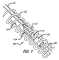
図5〜7は、本発明に従った埋込型デバイス解放機構130の別の好ましい実施形態を示す。概して、解放機構130は、上記の解放機構110と同様である。しかしながら、本解放機構130は、2つの上記の管122および124の代わりに、単一管132を含む。
5-7 illustrate another preferred embodiment of an implantable
この好ましい実施形態では、単一管132は、開口または切り取り部分132Aを含む。テザー116は、分離マンドレル118を覆ってループ状にされ、切り取り部分132Aを通過する。本側面では、分離マンドレル118が上記のデバイス解放制御108によって近位に移動させられるにつれて、テザー116のループ状部分は、分離マンドレル118を外れ、切り取り部分132Aの外に摺動し、デバイス104を解放する。
In this preferred embodiment, the
好ましくは、開口または切り取り部分132Aは、1つの管のレーザーもしくは機械的切断、または2つの管の接着によって形成され得る。また、切り取り部分132Aは、好ましくは、テザー116に対する擦れまたは摩擦を防止し、それによってテザー116の損傷を最小限に抑えるために、傾斜切断部(すなわち、管132の長さに対して90度ではない縁面)を含む。好ましくは、開口132Aの少なくとも遠位部分は、90度ではない切断角(すなわち、テザー116が置かれる部分)を有する。一実施例では、開口132Aの少なくとも遠位部分は、管132の長さの軸に対して約10〜80度の間の切断角を有する。
Preferably, the opening or cut-out
解放機構110および130に関してすでに記載したように、テザー116の自由端は、テザー116が患者に対して合併症の大きなリスクとなり得る場合の手技に対して、送達デバイス100(例えば、コイル112)に接続され得る。代替として、テザー116は、テザー116が患者にもたらす合併症のリスクが低い場合の手技に対して、埋込後にインプラント104と共に残り得る(すなわち、テザーの両方の自由端がインプラント104に接続される)。テザー116は、患者の中に残るか、あるいは生分解性材料から成る場合、分解する。
As already described with respect to the
図8および9は、本発明に従った解放機構140の別の好ましい実施形態の一部として、代替のテザー構成を示す。図8の非解放位置で最もよくわかるように、テザー116の自由端は、外側コイル112に固定される(例えば、接着剤、結束、または同様の固定方法)。テザー116は、デバイス104の開口を通って、またはスポークもしくはコイルの周囲を通り、次いで、切り取り部分132Aを通って、そして分離マンドレル118の周囲を通過する。
8 and 9 show an alternative tether configuration as part of another preferred embodiment of a
図9でわかるように、分離マンドレル118が近位に移動する時、テザー116のループ部分は、分離マンドレル118から摺動し外れる。テザー116は、デバイス104を通って摺動し、デバイス104を解放する。本側面では、テザー126は、送達システム100と共に患者から除去され、テザー116がそうでなければ患者における合併症(例えば、ステントと共に使用される場合の血栓)を引き起こすことを防止する。
As can be seen in FIG. 9, when the
特定の実施形態および用途に関して本発明を説明したが、当業者であれば、本教示に照らして、請求された発明の精神から逸脱すること、または範囲を超えることなく、付加的な実施形態および修正を生成することができるであろう。したがって、本明細書の図面および説明は、本発明の理解を促進するように一例として提供され、その範囲を限定すると解釈されるべきでないことを理解されたい。 Although the invention has been described with respect to particular embodiments and applications, those skilled in the art will recognize additional embodiments and embodiments without departing from or exceeding the scope of the claimed invention in light of the present teachings. A fix could be generated. Accordingly, it is to be understood that the drawings and descriptions herein are provided by way of example to facilitate understanding of the invention and should not be construed as limiting its scope.
Claims (14)
細長い本体と、
該細長い本体と関連付けられ、該細長い本体に沿って移動可能に整列されたインプラント捕捉部材と、
該インプラントに接続可能であり、該インプラント捕捉部材の周囲に少なくとも部分的に位置付けられたテザーと、
該インプラント捕捉部材と該テザーとを取り囲む外側コイルと
を備え、
該インプラント捕捉部材は、該テザーの位置を操作し、該インプラントの解放を引き起こすように所定の方向に移動可能であり、
該テザーは、第1の自由端および第2の自由端を備え、該第1の自由端および該第2の自由端のそれぞれは、該細長い本体に連結され、
該送達システムは、該細長い本体の遠位端付近に位置付けられた開放空間をさらに備え、該テザーは、該細長い本体を通過して該開放空間に入り、
該開放空間の少なくとも一部分を通る該インプラント捕捉部材の自由端の移動は、該テザーを該インプラント捕捉部材から解放する、
送達システム。 A delivery system for an implant, comprising:
An elongated body;
An implant capture member associated with the elongated body and movably aligned along the elongated body;
A tether connectable to the implant and positioned at least partially around the implant capture member;
An outer coil surrounding the implant capture member and the tether;
The implant capture member is movable in a predetermined direction to manipulate the position of the tether and cause release of the implant;
The tether comprises a first free end and a second free end, each of the first free end and the second free end being coupled to the elongated body ;
The delivery system further comprises an open space positioned near the distal end of the elongate body, the tether passes through the elongate body and enters the open space;
Movement of the free end of the implant capture member through at least a portion of the open space releases the tether from the implant capture member ;
Delivery system.
細長い本体と、
該細長い本体の遠位端付近に配置されたインプラント解放機構であって、該細長い本体内に摺動可能に配置されたインプラント捕捉部材を備えているインプラント解放機構と、
該インプラントを該細長い本体に保持するように、該インプラントおよび該インプラント捕捉部材に接続可能であるテザーと、
該インプラント捕捉部材と該テザーとを取り囲む外側コイルと
を備え、
該インプラント捕捉部材は、該テザーが、該インプラントを該細長い本体に保持することから解放されるように、所定の軸方向に摺動可能であり、
該テザーは、第1の自由端および第2の自由端を備え、該第1の自由端および該第2の自由端のそれぞれは、該細長い本体に連結され、
該送達システムは、該細長い本体の遠位端付近に位置付けられた開放空間をさらに備え、該テザーは、該細長い本体を通過して該開放空間に入り、
該開放空間の少なくとも一部分を通る該インプラント捕捉部材の自由端の移動は、該テザーを該インプラント捕捉部材から解放する、
送達システム。 A delivery system for an implant, comprising:
An elongated body;
An implant release mechanism disposed near a distal end of the elongate body, the implant release mechanism comprising an implant capture member slidably disposed within the elongate body;
A tether connectable to the implant and the implant capture member to hold the implant to the elongated body;
An outer coil surrounding the implant capture member and the tether;
The implant capture member is slidable in a predetermined axial direction such that the tether is released from holding the implant to the elongated body;
The tether comprises a first free end and a second free end, each of the first free end and the second free end being coupled to the elongated body ;
The delivery system further comprises an open space positioned near the distal end of the elongate body, the tether passes through the elongate body and enters the open space;
Movement of the free end of the implant capture member through at least a portion of the open space releases the tether from the implant capture member ;
Delivery system.
脈管系を通る前進のためにサイズ決定された請求項1に記載の送達システムと、
該送達システムの近位端において作動させられるように構成された解放制御と、
を備え、
該送達システムの前記インプラント捕捉部材は、前記テザーを該インプラント捕捉部材から解放するように摺動可能に後退させられるように構成される、システム。 A system for releasing an implant,
The delivery system of claim 1 sized for advancement through the vasculature;
A release control configured to be actuated at a proximal end of the delivery system;
With
The system wherein the implant capture member of the delivery system is configured to be slidably retracted to release the tether from the implant capture member.
Applications Claiming Priority (3)
| Application Number | Priority Date | Filing Date | Title |
|---|---|---|---|
| US16963209P | 2009-04-15 | 2009-04-15 | |
| US61/169,632 | 2009-04-15 | ||
| PCT/US2010/031268 WO2010121049A1 (en) | 2009-04-15 | 2010-04-15 | Implant delivery system |
Related Child Applications (1)
| Application Number | Title | Priority Date | Filing Date |
|---|---|---|---|
| JP2015055915A Division JP2015110113A (en) | 2009-04-15 | 2015-03-19 | Implant delivery system |
Publications (3)
| Publication Number | Publication Date |
|---|---|
| JP2012523933A JP2012523933A (en) | 2012-10-11 |
| JP2012523933A5 JP2012523933A5 (en) | 2013-05-16 |
| JP5771188B2 true JP5771188B2 (en) | 2015-08-26 |
Family
ID=42981556
Family Applications (2)
| Application Number | Title | Priority Date | Filing Date |
|---|---|---|---|
| JP2012506233A Active JP5771188B2 (en) | 2009-04-15 | 2010-04-15 | Implant delivery system |
| JP2015055915A Withdrawn JP2015110113A (en) | 2009-04-15 | 2015-03-19 | Implant delivery system |
Family Applications After (1)
| Application Number | Title | Priority Date | Filing Date |
|---|---|---|---|
| JP2015055915A Withdrawn JP2015110113A (en) | 2009-04-15 | 2015-03-19 | Implant delivery system |
Country Status (9)
| Country | Link |
|---|---|
| US (1) | US9968358B2 (en) |
| EP (1) | EP2419041B1 (en) |
| JP (2) | JP5771188B2 (en) |
| KR (1) | KR101828088B1 (en) |
| CN (1) | CN102596083B (en) |
| AU (1) | AU2010236349B2 (en) |
| BR (1) | BRPI1014971A2 (en) |
| CA (1) | CA2758511C (en) |
| WO (1) | WO2010121049A1 (en) |
Families Citing this family (73)
| Publication number | Priority date | Publication date | Assignee | Title |
|---|---|---|---|---|
| US8425549B2 (en) | 2002-07-23 | 2013-04-23 | Reverse Medical Corporation | Systems and methods for removing obstructive matter from body lumens and treating vascular defects |
| US10123803B2 (en) | 2007-10-17 | 2018-11-13 | Covidien Lp | Methods of managing neurovascular obstructions |
| US9198687B2 (en) | 2007-10-17 | 2015-12-01 | Covidien Lp | Acute stroke revascularization/recanalization systems processes and products thereby |
| US8926680B2 (en) | 2007-11-12 | 2015-01-06 | Covidien Lp | Aneurysm neck bridging processes with revascularization systems methods and products thereby |
| US8088140B2 (en) | 2008-05-19 | 2012-01-03 | Mindframe, Inc. | Blood flow restorative and embolus removal methods |
| US8066757B2 (en) | 2007-10-17 | 2011-11-29 | Mindframe, Inc. | Blood flow restoration and thrombus management methods |
| US9220522B2 (en) | 2007-10-17 | 2015-12-29 | Covidien Lp | Embolus removal systems with baskets |
| US8585713B2 (en) | 2007-10-17 | 2013-11-19 | Covidien Lp | Expandable tip assembly for thrombus management |
| US11337714B2 (en) | 2007-10-17 | 2022-05-24 | Covidien Lp | Restoring blood flow and clot removal during acute ischemic stroke |
| CA2710146C (en) | 2007-12-21 | 2017-03-28 | Microvention, Inc. | System and method for locating detachment zone of a detachable implant |
| AU2008345596B2 (en) | 2007-12-21 | 2013-09-05 | Microvention, Inc. | A system and method of detecting implant detachment |
| BRPI0908500A8 (en) | 2008-02-22 | 2018-10-23 | Micro Therapeutics Inc | imaging methods of restoration of thrombus-occluded blood vessel blood flow, partial or substantial dissolution and thrombus dislocation, self-expanding thrombus removal equipment and integrated removable thrombus mass |
| AU2009234268A1 (en) | 2008-04-11 | 2009-10-15 | Covidien Lp | Monorail neuro-microcatheter for delivery of medical devices to treat stroke, processes and products thereby |
| DK2265193T3 (en) | 2008-04-21 | 2012-01-23 | Nfocus Neuromedical Inc | Embolic devices with braided ball and delivery systems |
| US9675482B2 (en) | 2008-05-13 | 2017-06-13 | Covidien Lp | Braid implant delivery systems |
| US9387312B2 (en) | 2008-09-15 | 2016-07-12 | Brightwater Medical, Inc. | Convertible nephroureteral catheter |
| FR2946865B1 (en) * | 2009-06-17 | 2012-08-31 | Perouse Lab | DEVICE FOR TREATING A BLOOD CIRCULATION CONDUIT |
| US9956100B2 (en) | 2009-09-15 | 2018-05-01 | Brightwater Medical, Inc. | Systems and methods for coupling and decoupling a catheter |
| WO2011130081A1 (en) | 2010-04-14 | 2011-10-20 | Microvention, Inc. | Implant delivery device |
| US8579964B2 (en) | 2010-05-05 | 2013-11-12 | Neovasc Inc. | Transcatheter mitral valve prosthesis |
| WO2012002944A1 (en) | 2010-06-29 | 2012-01-05 | Artventive Medical Group, Inc. | Reducing flow through a tubular structure |
| US9247942B2 (en) | 2010-06-29 | 2016-02-02 | Artventive Medical Group, Inc. | Reversible tubal contraceptive device |
| JP6087281B2 (en) | 2010-09-10 | 2017-03-01 | メディナ メディカル,インコーポレイテッド | Device and method for treating vascular abnormalities |
| US8998947B2 (en) | 2010-09-10 | 2015-04-07 | Medina Medical, Inc. | Devices and methods for the treatment of vascular defects |
| US9149277B2 (en) | 2010-10-18 | 2015-10-06 | Artventive Medical Group, Inc. | Expandable device delivery |
| DE102011015738A1 (en) * | 2011-03-31 | 2012-10-04 | Variomed Ag | Stent for transluminal implantation in hollow organs and introducer catheter |
| US9554897B2 (en) | 2011-04-28 | 2017-01-31 | Neovasc Tiara Inc. | Methods and apparatus for engaging a valve prosthesis with tissue |
| US9308087B2 (en) | 2011-04-28 | 2016-04-12 | Neovasc Tiara Inc. | Sequentially deployed transcatheter mitral valve prosthesis |
| US9364359B2 (en) | 2011-12-08 | 2016-06-14 | W. L. Gore & Associates, Inc. | Systems and methods for delivery of a medical device |
| GB2501714B (en) * | 2012-05-02 | 2014-05-07 | Cook Medical Technologies Llc | Implant delivery system |
| US9345573B2 (en) | 2012-05-30 | 2016-05-24 | Neovasc Tiara Inc. | Methods and apparatus for loading a prosthesis onto a delivery system |
| US20140135811A1 (en) | 2012-11-13 | 2014-05-15 | Covidien Lp | Occlusive devices |
| US9095344B2 (en) * | 2013-02-05 | 2015-08-04 | Artventive Medical Group, Inc. | Methods and apparatuses for blood vessel occlusion |
| US8984733B2 (en) | 2013-02-05 | 2015-03-24 | Artventive Medical Group, Inc. | Bodily lumen occlusion |
| JP6615743B2 (en) * | 2013-03-12 | 2019-12-04 | アボット カーディオバスキュラー システムズ インコーポレイテッド | Catheter with movable tubular structure and proximal stopper |
| EP3000406A1 (en) * | 2013-03-14 | 2016-03-30 | Incumedx Inc. | Implants and methods of manufacturing the same |
| US9572665B2 (en) | 2013-04-04 | 2017-02-21 | Neovasc Tiara Inc. | Methods and apparatus for delivering a prosthetic valve to a beating heart |
| US10149968B2 (en) | 2013-06-14 | 2018-12-11 | Artventive Medical Group, Inc. | Catheter-assisted tumor treatment |
| US9737308B2 (en) | 2013-06-14 | 2017-08-22 | Artventive Medical Group, Inc. | Catheter-assisted tumor treatment |
| US9737306B2 (en) | 2013-06-14 | 2017-08-22 | Artventive Medical Group, Inc. | Implantable luminal devices |
| US9636116B2 (en) | 2013-06-14 | 2017-05-02 | Artventive Medical Group, Inc. | Implantable luminal devices |
| JP5896478B2 (en) * | 2013-09-24 | 2016-03-30 | 朝日インテック株式会社 | Balloon catheter |
| CN103690202B (en) * | 2013-12-30 | 2016-04-20 | 先健科技(深圳)有限公司 | The conveyer device of implant and implanted medical device |
| US10363043B2 (en) | 2014-05-01 | 2019-07-30 | Artventive Medical Group, Inc. | Treatment of incompetent vessels |
| JP6688509B2 (en) * | 2014-08-12 | 2020-04-28 | メリット・メディカル・システムズ・インコーポレイテッドMerit Medical Systems,Inc. | System and method for connecting and disconnecting catheters |
| DE202014104330U1 (en) * | 2014-09-12 | 2015-12-16 | Pfm Medical Ag | Device for inserting a medical implant into a human or animal body |
| CN107205795B (en) * | 2014-12-09 | 2021-02-02 | 拜奥美特3i有限责任公司 | Robotic device for dental surgery |
| US9375333B1 (en) | 2015-03-06 | 2016-06-28 | Covidien Lp | Implantable device detachment systems and associated devices and methods |
| US10130821B2 (en) | 2015-04-24 | 2018-11-20 | Medtronic, Inc. | Interventional medical systems and associated tethering assemblies and methods |
| US9468773B1 (en) | 2015-05-07 | 2016-10-18 | Medtronic, Inc. | Interventional medical systems and implantable medical devices including tethering features, and associated methods |
| US11090055B2 (en) | 2015-10-30 | 2021-08-17 | Incumedx Inc. | Devices and methods for delivering an implant to a vascular disorder |
| US10052108B2 (en) | 2015-10-30 | 2018-08-21 | Incumedx, Inc. | Devices and methods for delivering an implant to a vascular disorder |
| DE202017007326U1 (en) | 2016-01-29 | 2020-10-20 | Neovasc Tiara Inc. | Valve prosthesis to prevent flow obstruction |
| US10813644B2 (en) | 2016-04-01 | 2020-10-27 | Artventive Medical Group, Inc. | Occlusive implant and delivery system |
| US10350408B2 (en) * | 2016-04-28 | 2019-07-16 | Medtronic, Inc. | Interventional medical systems, associated assemblies and methods |
| CN110859692B (en) * | 2016-07-29 | 2021-11-23 | 上海沃比医疗科技有限公司 | Implant delivery system |
| US10478195B2 (en) | 2016-08-04 | 2019-11-19 | Covidien Lp | Devices, systems, and methods for the treatment of vascular defects |
| EP3506840A4 (en) | 2016-09-01 | 2020-05-06 | Microvention, Inc. | Temporary aortic occlusion device |
| EP3541462A4 (en) | 2016-11-21 | 2020-06-17 | Neovasc Tiara Inc. | Methods and systems for rapid retraction of a transcatheter heart valve delivery system |
| GB201713329D0 (en) * | 2017-08-18 | 2017-10-04 | Clearstream Tech Ltd | An implant system comprising a delivery wire assembly and an implant |
| US10675036B2 (en) | 2017-08-22 | 2020-06-09 | Covidien Lp | Devices, systems, and methods for the treatment of vascular defects |
| WO2019036810A1 (en) | 2017-08-25 | 2019-02-28 | Neovasc Tiara Inc. | Sequentially deployed transcatheter mitral valve prosthesis |
| CA3118599A1 (en) | 2018-11-08 | 2020-05-14 | Neovasc Tiara Inc. | Ventricular deployment of a transcatheter mitral valve prosthesis |
| CN111388045A (en) | 2018-12-17 | 2020-07-10 | 柯惠有限合伙公司 | Occlusion device |
| EP3946163A4 (en) | 2019-04-01 | 2022-12-21 | Neovasc Tiara Inc. | Controllably deployable prosthetic valve |
| AU2020271896B2 (en) | 2019-04-10 | 2022-10-13 | Neovasc Tiara Inc. | Prosthetic valve with natural blood flow |
| EP3972673A4 (en) | 2019-05-20 | 2023-06-07 | Neovasc Tiara Inc. | Introducer with hemostasis mechanism |
| AU2020295566B2 (en) | 2019-06-20 | 2023-07-20 | Neovasc Tiara Inc. | Low profile prosthetic mitral valve |
| US11685007B2 (en) | 2019-11-04 | 2023-06-27 | Covidien Lp | Devices, systems, and methods for treatment of intracranial aneurysms |
| IT202000006286A1 (en) * | 2020-03-25 | 2021-09-25 | Pfm Medical Ag | SYSTEM ZUR IMPLANTATION EINES MEDIZINISCHEN IMPLANTATS IM MENSCHLICHEN ODER TIERISCHEN KÖRPER |
| US11931041B2 (en) | 2020-05-12 | 2024-03-19 | Covidien Lp | Devices, systems, and methods for the treatment of vascular defects |
| CN116472012A (en) * | 2020-10-28 | 2023-07-21 | 纳米支架公司 | Catheter accessory for increasing the pushability of a catheter |
| CN117442258B (en) * | 2023-12-22 | 2024-04-23 | 北京迈迪顶峰医疗科技股份有限公司 | Conveying device and binding method thereof |
Family Cites Families (66)
| Publication number | Priority date | Publication date | Assignee | Title |
|---|---|---|---|---|
| US4346712A (en) | 1979-04-06 | 1982-08-31 | Kuraray Company, Ltd. | Releasable balloon catheter |
| US5122136A (en) | 1990-03-13 | 1992-06-16 | The Regents Of The University Of California | Endovascular electrolytically detachable guidewire tip for the electroformation of thrombus in arteries, veins, aneurysms, vascular malformations and arteriovenous fistulas |
| US5108407A (en) | 1990-06-08 | 1992-04-28 | Rush-Presbyterian St. Luke's Medical Center | Method and apparatus for placement of an embolic coil |
| US5147370A (en) * | 1991-06-12 | 1992-09-15 | Mcnamara Thomas O | Nitinol stent for hollow body conduits |
| US5242452A (en) * | 1991-10-11 | 1993-09-07 | Kanji Inoue | Device for collapsing an appliance collapsible for insertion into human organs |
| US5290305A (en) * | 1991-10-11 | 1994-03-01 | Kanji Inoue | Appliance collapsible for insertion into human organs and capable of resilient restoration |
| US5261916A (en) * | 1991-12-12 | 1993-11-16 | Target Therapeutics | Detachable pusher-vasoocclusive coil assembly with interlocking ball and keyway coupling |
| JP3393383B2 (en) * | 1992-01-21 | 2003-04-07 | リージェンツ オブ ザ ユニバーシティ オブ ミネソタ | Septal defect closure device |
| IL106946A0 (en) * | 1992-09-22 | 1993-12-28 | Target Therapeutics Inc | Detachable embolic coil assembly |
| US5250071A (en) * | 1992-09-22 | 1993-10-05 | Target Therapeutics, Inc. | Detachable embolic coil assembly using interlocking clasps and method of use |
| US5383853A (en) * | 1992-11-12 | 1995-01-24 | Medtronic, Inc. | Rapid exchange catheter |
| CA2159734A1 (en) * | 1993-03-30 | 1994-10-13 | Rafael Beyar | Temporary stent system |
| US5925059A (en) * | 1993-04-19 | 1999-07-20 | Target Therapeutics, Inc. | Detachable embolic coil assembly |
| US5800453A (en) * | 1993-04-19 | 1998-09-01 | Target Therapeutics, Inc. | Detachable embolic coil assembly using interlocking hooks and slots |
| DE69419877T2 (en) * | 1993-11-04 | 1999-12-16 | Bard Inc C R | Fixed vascular prosthesis |
| US5578074A (en) | 1994-12-22 | 1996-11-26 | Target Therapeutics, Inc. | Implant delivery method and assembly |
| US5814062A (en) * | 1994-12-22 | 1998-09-29 | Target Therapeutics, Inc. | Implant delivery assembly with expandable coupling/decoupling mechanism |
| US5676671A (en) * | 1995-04-12 | 1997-10-14 | Inoue; Kanji | Device for introducing an appliance to be implanted into a catheter |
| US6270520B1 (en) * | 1995-05-19 | 2001-08-07 | Kanji Inoue | Appliance to be implanted, method of collapsing the appliance to be implanted and method of using the appliance to be implanted |
| WO1996036297A1 (en) * | 1995-05-19 | 1996-11-21 | Kanji Inoue | Transplantation instrument, method of bending same and method of transplanting same |
| US5582619A (en) | 1995-06-30 | 1996-12-10 | Target Therapeutics, Inc. | Stretch resistant vaso-occlusive coils |
| CN1568905B (en) * | 1996-06-20 | 2010-04-28 | 瓦斯卡泰克有限公司 | Prosthesis reparation of body conduit |
| US5984929A (en) * | 1997-08-29 | 1999-11-16 | Target Therapeutics, Inc. | Fast detaching electronically isolated implant |
| US6048338A (en) * | 1997-10-15 | 2000-04-11 | Scimed Life Systems, Inc. | Catheter with spiral cut transition member |
| US6478773B1 (en) | 1998-12-21 | 2002-11-12 | Micrus Corporation | Apparatus for deployment of micro-coil using a catheter |
| US6500149B2 (en) | 1998-08-31 | 2002-12-31 | Deepak Gandhi | Apparatus for deployment of micro-coil using a catheter |
| WO2000025847A1 (en) * | 1998-10-29 | 2000-05-11 | Kanji Inoue | Guiding device of instruments |
| EP1136044A1 (en) * | 1999-10-04 | 2001-09-26 | Kanji Inoue | Method of folding transplanting instrument and transplanting instrument |
| US6602261B2 (en) | 1999-10-04 | 2003-08-05 | Microvention, Inc. | Filamentous embolic device with expansile elements |
| WO2001054761A2 (en) * | 2000-01-28 | 2001-08-02 | William Cook, Europe Aps | Endovascular medical device with plurality of wires |
| US6740073B1 (en) | 2000-12-06 | 2004-05-25 | Advanced Cardiovascular Systems, Inc. | Guiding catheter reinforcement with angled distal end |
| US6585718B2 (en) * | 2001-05-02 | 2003-07-01 | Cardiac Pacemakers, Inc. | Steerable catheter with shaft support system for resisting axial compressive loads |
| EP2319430B1 (en) | 2001-05-29 | 2013-11-13 | Microvention, Inc. | Vascular embolization device and method of manufacture |
| US7011671B2 (en) * | 2001-07-18 | 2006-03-14 | Atritech, Inc. | Cardiac implant device tether system and method |
| US7226466B2 (en) * | 2001-09-06 | 2007-06-05 | Nmt Medical, Inc. | Flexible delivery system |
| EP1469790B1 (en) * | 2002-01-25 | 2016-10-19 | Atritech, Inc. | Atrial appendage blood filtration systems |
| CA2486390C (en) * | 2002-05-29 | 2011-01-04 | William A. Cook Australia Pty. Ltd. | Trigger wire system for a prosthesis deployment device |
| US7608058B2 (en) | 2002-07-23 | 2009-10-27 | Micrus Corporation | Stretch resistant therapeutic device |
| US20050171572A1 (en) | 2002-07-31 | 2005-08-04 | Microvention, Inc. | Multi-layer coaxial vaso-occlusive device |
| US7316708B2 (en) | 2002-12-05 | 2008-01-08 | Cardiac Dimensions, Inc. | Medical device delivery system |
| US20050149108A1 (en) * | 2003-12-17 | 2005-07-07 | Microvention, Inc. | Implant delivery and detachment system and method |
| US7316709B2 (en) * | 2004-01-13 | 2008-01-08 | Advanced Cardiovascular Systems, Inc. | Balloon catheter having a textured member for enhancing balloon or stent retention |
| JP5087399B2 (en) * | 2004-08-25 | 2012-12-05 | マイクロベンション インコーポレイテッド | Thermal desorption system for implantable devices |
| US20060116714A1 (en) * | 2004-11-26 | 2006-06-01 | Ivan Sepetka | Coupling and release devices and methods for their assembly and use |
| US7811305B2 (en) * | 2005-06-02 | 2010-10-12 | Codman & Shurtleff, Inc. | Stretch resistant embolic coil delivery system with spring release mechanism |
| US7985238B2 (en) * | 2005-06-02 | 2011-07-26 | Codman & Shurtleff, Inc. | Embolic coil delivery system with spring wire release mechanism |
| US7819891B2 (en) * | 2005-06-02 | 2010-10-26 | Codman & Shurtleff, Inc. | Stretch resistant embolic coil delivery system with spring release mechanism |
| US20060276827A1 (en) * | 2005-06-02 | 2006-12-07 | Vladimir Mitelberg | Stretch resistant embolic coil delivery system with mechanical release mechanism |
| US7367987B2 (en) * | 2005-06-02 | 2008-05-06 | Cordis Neurovascular, Inc. | Stretch resistant embolic coil delivery system with mechanical release mechanism |
| US7708754B2 (en) * | 2005-06-02 | 2010-05-04 | Codman & Shurtleff, Pc | Stretch resistant embolic coil delivery system with mechanical release mechanism |
| US7708755B2 (en) * | 2005-06-02 | 2010-05-04 | Codman & Shurtleff Inc. | Stretch resistant embolic coil delivery system with combined mechanical and pressure release mechanism |
| US7371251B2 (en) * | 2005-06-02 | 2008-05-13 | Cordis Neurovascular, Inc. | Stretch resistant embolic coil delivery system with mechanical release mechanism |
| US9636115B2 (en) * | 2005-06-14 | 2017-05-02 | Stryker Corporation | Vaso-occlusive delivery device with kink resistant, flexible distal end |
| US7628797B2 (en) * | 2006-01-31 | 2009-12-08 | Edwards Lifesciences Corporation | System, apparatus, and method for fastening tissue |
| US8157837B2 (en) * | 2006-03-13 | 2012-04-17 | Pneumrx, Inc. | Minimally invasive lung volume reduction device and method |
| US9510962B2 (en) * | 2006-06-16 | 2016-12-06 | Olympus Corporation | Stent delivery system |
| US8062325B2 (en) * | 2006-07-31 | 2011-11-22 | Codman & Shurtleff, Inc. | Implantable medical device detachment system and methods of using the same |
| US8840655B2 (en) * | 2006-08-09 | 2014-09-23 | Coherex Medical, Inc. | Systems and devices for reducing the size of an internal tissue opening |
| JP2010500130A (en) * | 2006-08-09 | 2010-01-07 | コヒーレックス メディカル インコーポレイテッド | Device for reducing the size of internal tissue pores |
| WO2008064205A2 (en) * | 2006-11-20 | 2008-05-29 | Boston Scientific Limited | Mechanically detachable vaso-occlusive device |
| EP2131918B1 (en) * | 2007-03-19 | 2014-04-23 | Boston Scientific Neuromodulation Corporation | Mri and rf compatible leads and related methods of operating and fabricating leads |
| US20080283066A1 (en) * | 2007-05-17 | 2008-11-20 | Cardiac Pacemakers, Inc. | Delivery device for implantable sensors |
| US8226701B2 (en) * | 2007-09-26 | 2012-07-24 | Trivascular, Inc. | Stent and delivery system for deployment thereof |
| US8034094B2 (en) * | 2008-06-11 | 2011-10-11 | Olympus Medical Systems Corp. | Stent delivery system and stent delivery method |
| KR20110043799A (en) * | 2009-10-16 | 2011-04-28 | 강호창 | Micro-coil assembly |
| US8828051B2 (en) * | 2010-07-02 | 2014-09-09 | Pfm Medical Ag | Left atrial appendage occlusion device |
-
2010
- 2010-04-15 BR BRPI1014971A patent/BRPI1014971A2/en not_active Application Discontinuation
- 2010-04-15 AU AU2010236349A patent/AU2010236349B2/en active Active
- 2010-04-15 WO PCT/US2010/031268 patent/WO2010121049A1/en active Application Filing
- 2010-04-15 EP EP10765197.8A patent/EP2419041B1/en active Active
- 2010-04-15 KR KR1020117026779A patent/KR101828088B1/en active IP Right Grant
- 2010-04-15 CA CA2758511A patent/CA2758511C/en active Active
- 2010-04-15 JP JP2012506233A patent/JP5771188B2/en active Active
- 2010-04-15 US US12/761,187 patent/US9968358B2/en active Active
- 2010-04-15 CN CN201080026668.3A patent/CN102596083B/en active Active
-
2015
- 2015-03-19 JP JP2015055915A patent/JP2015110113A/en not_active Withdrawn
Also Published As
| Publication number | Publication date |
|---|---|
| CA2758511C (en) | 2017-06-27 |
| US20100268201A1 (en) | 2010-10-21 |
| JP2015110113A (en) | 2015-06-18 |
| CN102596083B (en) | 2016-11-16 |
| US9968358B2 (en) | 2018-05-15 |
| EP2419041B1 (en) | 2017-06-21 |
| KR101828088B1 (en) | 2018-02-09 |
| CN102596083A (en) | 2012-07-18 |
| BRPI1014971A2 (en) | 2016-04-26 |
| AU2010236349B2 (en) | 2015-04-02 |
| WO2010121049A9 (en) | 2010-12-02 |
| KR20120025466A (en) | 2012-03-15 |
| WO2010121049A1 (en) | 2010-10-21 |
| EP2419041A4 (en) | 2015-11-04 |
| CA2758511A1 (en) | 2010-10-21 |
| AU2010236349A1 (en) | 2011-11-17 |
| EP2419041A1 (en) | 2012-02-22 |
| JP2012523933A (en) | 2012-10-11 |
Similar Documents
| Publication | Publication Date | Title |
|---|---|---|
| JP5771188B2 (en) | Implant delivery system | |
| JP5597309B2 (en) | Prosthesis placement equipment with controlled release and recovery | |
| US10034670B2 (en) | Medical implant detachment mechanism and introducer assembly | |
| JP5073300B2 (en) | Delivery of therapeutic devices | |
| EP3102160B1 (en) | Telescoping stent | |
| EP3017794B1 (en) | Deployment handle for a prosthesis delivery device | |
| JP7183153B2 (en) | Methods and apparatus for stent delivery | |
| US7344558B2 (en) | Embolic device delivery system | |
| AU2009271596B2 (en) | Introducer for endovascular implants | |
| JP2018140198A (en) | Rapid exchange stent delivery system | |
| EP3143968A1 (en) | Prosthesis delivery device | |
| JP2009513274A (en) | CONNECTING AND RELEASE DEVICE AND METHOD FOR ASSEMBLING AND USING THE SAME | |
| JP2010536418A (en) | Placement device | |
| EP3040058A1 (en) | Deployment handle for a delivery device with mechanism for quick release of a prosthesis and re-sheathing of device tip | |
| JP2001519694A (en) | Stent / graft delivery system and method of use | |
| JP2009530030A (en) | Medical gripping device | |
| US20120203322A1 (en) | Quick release mechanism for medical device deployment | |
| WO2007070788A2 (en) | Rotational detachment mechanism | |
| US20230277186A1 (en) | Elongating wires for inhibiting premature implant detachment | |
| JP2023100597A (en) | System and method for inhibiting premature embolic implant deployment | |
| US10406320B1 (en) | Systems and methods for sheath retraction |
Legal Events
| Date | Code | Title | Description |
|---|---|---|---|
| A521 | Request for written amendment filed |
Free format text: JAPANESE INTERMEDIATE CODE: A523 Effective date: 20130328 |
|
| A621 | Written request for application examination |
Free format text: JAPANESE INTERMEDIATE CODE: A621 Effective date: 20130328 |
|
| A977 | Report on retrieval |
Free format text: JAPANESE INTERMEDIATE CODE: A971007 Effective date: 20140124 |
|
| A131 | Notification of reasons for refusal |
Free format text: JAPANESE INTERMEDIATE CODE: A131 Effective date: 20140212 |
|
| A601 | Written request for extension of time |
Free format text: JAPANESE INTERMEDIATE CODE: A601 Effective date: 20140509 |
|
| A602 | Written permission of extension of time |
Free format text: JAPANESE INTERMEDIATE CODE: A602 Effective date: 20140516 |
|
| A521 | Request for written amendment filed |
Free format text: JAPANESE INTERMEDIATE CODE: A523 Effective date: 20140606 |
|
| A02 | Decision of refusal |
Free format text: JAPANESE INTERMEDIATE CODE: A02 Effective date: 20141119 |
|
| A521 | Request for written amendment filed |
Free format text: JAPANESE INTERMEDIATE CODE: A523 Effective date: 20150319 |
|
| A911 | Transfer to examiner for re-examination before appeal (zenchi) |
Free format text: JAPANESE INTERMEDIATE CODE: A911 Effective date: 20150410 |
|
| TRDD | Decision of grant or rejection written | ||
| A01 | Written decision to grant a patent or to grant a registration (utility model) |
Free format text: JAPANESE INTERMEDIATE CODE: A01 Effective date: 20150610 |
|
| A61 | First payment of annual fees (during grant procedure) |
Free format text: JAPANESE INTERMEDIATE CODE: A61 Effective date: 20150626 |
|
| R150 | Certificate of patent or registration of utility model |
Ref document number: 5771188 Country of ref document: JP Free format text: JAPANESE INTERMEDIATE CODE: R150 |
|
| R250 | Receipt of annual fees |
Free format text: JAPANESE INTERMEDIATE CODE: R250 |
|
| RD04 | Notification of resignation of power of attorney |
Free format text: JAPANESE INTERMEDIATE CODE: R3D04 |
|
| R250 | Receipt of annual fees |
Free format text: JAPANESE INTERMEDIATE CODE: R250 |
|
| R250 | Receipt of annual fees |
Free format text: JAPANESE INTERMEDIATE CODE: R250 |
|
| R250 | Receipt of annual fees |
Free format text: JAPANESE INTERMEDIATE CODE: R250 |
|
| R250 | Receipt of annual fees |
Free format text: JAPANESE INTERMEDIATE CODE: R250 |
|
| R250 | Receipt of annual fees |
Free format text: JAPANESE INTERMEDIATE CODE: R250 |