EP3017794B1 - Deployment handle for a prosthesis delivery device - Google Patents
Deployment handle for a prosthesis delivery device Download PDFInfo
- Publication number
- EP3017794B1 EP3017794B1 EP15193071.6A EP15193071A EP3017794B1 EP 3017794 B1 EP3017794 B1 EP 3017794B1 EP 15193071 A EP15193071 A EP 15193071A EP 3017794 B1 EP3017794 B1 EP 3017794B1
- Authority
- EP
- European Patent Office
- Prior art keywords
- handle
- prosthesis
- main handle
- suture
- delivery device
- Prior art date
- Legal status (The legal status is an assumption and is not a legal conclusion. Google has not performed a legal analysis and makes no representation as to the accuracy of the status listed.)
- Active
Links
- 230000007246 mechanism Effects 0.000 claims description 131
- 230000014759 maintenance of location Effects 0.000 claims description 37
- 239000000463 material Substances 0.000 claims description 24
- 230000000694 effects Effects 0.000 claims description 16
- 238000000034 method Methods 0.000 description 26
- 230000003447 ipsilateral effect Effects 0.000 description 16
- 230000000670 limiting effect Effects 0.000 description 16
- 210000005166 vasculature Anatomy 0.000 description 9
- 238000004873 anchoring Methods 0.000 description 8
- 208000027418 Wounds and injury Diseases 0.000 description 5
- 239000000853 adhesive Substances 0.000 description 5
- 230000001070 adhesive effect Effects 0.000 description 5
- 229910052751 metal Inorganic materials 0.000 description 5
- 239000002184 metal Substances 0.000 description 5
- 244000208734 Pisonia aculeata Species 0.000 description 4
- 239000003433 contraceptive agent Substances 0.000 description 4
- 230000002254 contraceptive effect Effects 0.000 description 4
- 239000012530 fluid Substances 0.000 description 4
- 238000003384 imaging method Methods 0.000 description 4
- 229920000642 polymer Polymers 0.000 description 4
- 230000002829 reductive effect Effects 0.000 description 4
- 229910045601 alloy Inorganic materials 0.000 description 3
- 239000000956 alloy Substances 0.000 description 3
- 210000003484 anatomy Anatomy 0.000 description 3
- 230000008878 coupling Effects 0.000 description 3
- 238000010168 coupling process Methods 0.000 description 3
- 238000005859 coupling reaction Methods 0.000 description 3
- 238000002347 injection Methods 0.000 description 3
- 239000007924 injection Substances 0.000 description 3
- 238000003780 insertion Methods 0.000 description 3
- 230000037431 insertion Effects 0.000 description 3
- 230000036961 partial effect Effects 0.000 description 3
- 229920003023 plastic Polymers 0.000 description 3
- 239000004033 plastic Substances 0.000 description 3
- 229920001296 polysiloxane Polymers 0.000 description 3
- 230000002441 reversible effect Effects 0.000 description 3
- 238000007789 sealing Methods 0.000 description 3
- 230000009471 action Effects 0.000 description 2
- 238000005452 bending Methods 0.000 description 2
- 229910003460 diamond Inorganic materials 0.000 description 2
- 239000010432 diamond Substances 0.000 description 2
- 210000001105 femoral artery Anatomy 0.000 description 2
- 238000002594 fluoroscopy Methods 0.000 description 2
- 238000011010 flushing procedure Methods 0.000 description 2
- 239000007943 implant Substances 0.000 description 2
- 238000002513 implantation Methods 0.000 description 2
- 150000002739 metals Chemical class 0.000 description 2
- 230000000717 retained effect Effects 0.000 description 2
- 239000007787 solid Substances 0.000 description 2
- 238000011282 treatment Methods 0.000 description 2
- 230000000007 visual effect Effects 0.000 description 2
- 206010002329 Aneurysm Diseases 0.000 description 1
- 229920010741 Ultra High Molecular Weight Polyethylene (UHMWPE) Polymers 0.000 description 1
- 210000000709 aorta Anatomy 0.000 description 1
- 210000000702 aorta abdominal Anatomy 0.000 description 1
- 210000001367 artery Anatomy 0.000 description 1
- 230000006835 compression Effects 0.000 description 1
- 238000007906 compression Methods 0.000 description 1
- 238000013270 controlled release Methods 0.000 description 1
- 230000006378 damage Effects 0.000 description 1
- 230000001419 dependent effect Effects 0.000 description 1
- 230000002708 enhancing effect Effects 0.000 description 1
- -1 for example Inorganic materials 0.000 description 1
- 239000003292 glue Substances 0.000 description 1
- 230000036541 health Effects 0.000 description 1
- 230000023597 hemostasis Effects 0.000 description 1
- 208000014674 injury Diseases 0.000 description 1
- 235000011475 lollipops Nutrition 0.000 description 1
- 230000007257 malfunction Effects 0.000 description 1
- 238000004519 manufacturing process Methods 0.000 description 1
- 239000003550 marker Substances 0.000 description 1
- 230000007935 neutral effect Effects 0.000 description 1
- HLXZNVUGXRDIFK-UHFFFAOYSA-N nickel titanium Chemical compound [Ti].[Ti].[Ti].[Ti].[Ti].[Ti].[Ti].[Ti].[Ti].[Ti].[Ti].[Ni].[Ni].[Ni].[Ni].[Ni].[Ni].[Ni].[Ni].[Ni].[Ni].[Ni].[Ni].[Ni].[Ni] HLXZNVUGXRDIFK-UHFFFAOYSA-N 0.000 description 1
- 229910001000 nickel titanium Inorganic materials 0.000 description 1
- 210000000056 organ Anatomy 0.000 description 1
- 210000003101 oviduct Anatomy 0.000 description 1
- RVTZCBVAJQQJTK-UHFFFAOYSA-N oxygen(2-);zirconium(4+) Chemical compound [O-2].[O-2].[Zr+4] RVTZCBVAJQQJTK-UHFFFAOYSA-N 0.000 description 1
- 230000002028 premature Effects 0.000 description 1
- 230000001681 protective effect Effects 0.000 description 1
- 230000000452 restraining effect Effects 0.000 description 1
- 238000000926 separation method Methods 0.000 description 1
- 229910000679 solder Inorganic materials 0.000 description 1
- 239000010935 stainless steel Substances 0.000 description 1
- 229910001220 stainless steel Inorganic materials 0.000 description 1
- 230000001954 sterilising effect Effects 0.000 description 1
- 238000004659 sterilization and disinfection Methods 0.000 description 1
- 125000000391 vinyl group Chemical group [H]C([*])=C([H])[H] 0.000 description 1
- 229920002554 vinyl polymer Polymers 0.000 description 1
- 238000012800 visualization Methods 0.000 description 1
- 238000003466 welding Methods 0.000 description 1
Images


Classifications
-
- A—HUMAN NECESSITIES
- A61—MEDICAL OR VETERINARY SCIENCE; HYGIENE
- A61F—FILTERS IMPLANTABLE INTO BLOOD VESSELS; PROSTHESES; DEVICES PROVIDING PATENCY TO, OR PREVENTING COLLAPSING OF, TUBULAR STRUCTURES OF THE BODY, e.g. STENTS; ORTHOPAEDIC, NURSING OR CONTRACEPTIVE DEVICES; FOMENTATION; TREATMENT OR PROTECTION OF EYES OR EARS; BANDAGES, DRESSINGS OR ABSORBENT PADS; FIRST-AID KITS
- A61F2/00—Filters implantable into blood vessels; Prostheses, i.e. artificial substitutes or replacements for parts of the body; Appliances for connecting them with the body; Devices providing patency to, or preventing collapsing of, tubular structures of the body, e.g. stents
- A61F2/02—Prostheses implantable into the body
- A61F2/04—Hollow or tubular parts of organs, e.g. bladders, tracheae, bronchi or bile ducts
- A61F2/06—Blood vessels
- A61F2/07—Stent-grafts
-
- A—HUMAN NECESSITIES
- A61—MEDICAL OR VETERINARY SCIENCE; HYGIENE
- A61F—FILTERS IMPLANTABLE INTO BLOOD VESSELS; PROSTHESES; DEVICES PROVIDING PATENCY TO, OR PREVENTING COLLAPSING OF, TUBULAR STRUCTURES OF THE BODY, e.g. STENTS; ORTHOPAEDIC, NURSING OR CONTRACEPTIVE DEVICES; FOMENTATION; TREATMENT OR PROTECTION OF EYES OR EARS; BANDAGES, DRESSINGS OR ABSORBENT PADS; FIRST-AID KITS
- A61F2/00—Filters implantable into blood vessels; Prostheses, i.e. artificial substitutes or replacements for parts of the body; Appliances for connecting them with the body; Devices providing patency to, or preventing collapsing of, tubular structures of the body, e.g. stents
- A61F2/82—Devices providing patency to, or preventing collapsing of, tubular structures of the body, e.g. stents
-
- A—HUMAN NECESSITIES
- A61—MEDICAL OR VETERINARY SCIENCE; HYGIENE
- A61F—FILTERS IMPLANTABLE INTO BLOOD VESSELS; PROSTHESES; DEVICES PROVIDING PATENCY TO, OR PREVENTING COLLAPSING OF, TUBULAR STRUCTURES OF THE BODY, e.g. STENTS; ORTHOPAEDIC, NURSING OR CONTRACEPTIVE DEVICES; FOMENTATION; TREATMENT OR PROTECTION OF EYES OR EARS; BANDAGES, DRESSINGS OR ABSORBENT PADS; FIRST-AID KITS
- A61F2/00—Filters implantable into blood vessels; Prostheses, i.e. artificial substitutes or replacements for parts of the body; Appliances for connecting them with the body; Devices providing patency to, or preventing collapsing of, tubular structures of the body, e.g. stents
- A61F2/95—Instruments specially adapted for placement or removal of stents or stent-grafts
- A61F2/962—Instruments specially adapted for placement or removal of stents or stent-grafts having an outer sleeve
- A61F2/966—Instruments specially adapted for placement or removal of stents or stent-grafts having an outer sleeve with relative longitudinal movement between outer sleeve and prosthesis, e.g. using a push rod
- A61F2/9661—Instruments specially adapted for placement or removal of stents or stent-grafts having an outer sleeve with relative longitudinal movement between outer sleeve and prosthesis, e.g. using a push rod the proximal portion of the stent or stent-graft is released first
-
- A—HUMAN NECESSITIES
- A61—MEDICAL OR VETERINARY SCIENCE; HYGIENE
- A61F—FILTERS IMPLANTABLE INTO BLOOD VESSELS; PROSTHESES; DEVICES PROVIDING PATENCY TO, OR PREVENTING COLLAPSING OF, TUBULAR STRUCTURES OF THE BODY, e.g. STENTS; ORTHOPAEDIC, NURSING OR CONTRACEPTIVE DEVICES; FOMENTATION; TREATMENT OR PROTECTION OF EYES OR EARS; BANDAGES, DRESSINGS OR ABSORBENT PADS; FIRST-AID KITS
- A61F2/00—Filters implantable into blood vessels; Prostheses, i.e. artificial substitutes or replacements for parts of the body; Appliances for connecting them with the body; Devices providing patency to, or preventing collapsing of, tubular structures of the body, e.g. stents
- A61F2/95—Instruments specially adapted for placement or removal of stents or stent-grafts
- A61F2/9517—Instruments specially adapted for placement or removal of stents or stent-grafts handle assemblies therefor
-
- A—HUMAN NECESSITIES
- A61—MEDICAL OR VETERINARY SCIENCE; HYGIENE
- A61F—FILTERS IMPLANTABLE INTO BLOOD VESSELS; PROSTHESES; DEVICES PROVIDING PATENCY TO, OR PREVENTING COLLAPSING OF, TUBULAR STRUCTURES OF THE BODY, e.g. STENTS; ORTHOPAEDIC, NURSING OR CONTRACEPTIVE DEVICES; FOMENTATION; TREATMENT OR PROTECTION OF EYES OR EARS; BANDAGES, DRESSINGS OR ABSORBENT PADS; FIRST-AID KITS
- A61F2/00—Filters implantable into blood vessels; Prostheses, i.e. artificial substitutes or replacements for parts of the body; Appliances for connecting them with the body; Devices providing patency to, or preventing collapsing of, tubular structures of the body, e.g. stents
- A61F2/95—Instruments specially adapted for placement or removal of stents or stent-grafts
- A61F2002/9505—Instruments specially adapted for placement or removal of stents or stent-grafts having retaining means other than an outer sleeve, e.g. male-female connector between stent and instrument
-
- A—HUMAN NECESSITIES
- A61—MEDICAL OR VETERINARY SCIENCE; HYGIENE
- A61F—FILTERS IMPLANTABLE INTO BLOOD VESSELS; PROSTHESES; DEVICES PROVIDING PATENCY TO, OR PREVENTING COLLAPSING OF, TUBULAR STRUCTURES OF THE BODY, e.g. STENTS; ORTHOPAEDIC, NURSING OR CONTRACEPTIVE DEVICES; FOMENTATION; TREATMENT OR PROTECTION OF EYES OR EARS; BANDAGES, DRESSINGS OR ABSORBENT PADS; FIRST-AID KITS
- A61F2/00—Filters implantable into blood vessels; Prostheses, i.e. artificial substitutes or replacements for parts of the body; Appliances for connecting them with the body; Devices providing patency to, or preventing collapsing of, tubular structures of the body, e.g. stents
- A61F2/95—Instruments specially adapted for placement or removal of stents or stent-grafts
- A61F2/962—Instruments specially adapted for placement or removal of stents or stent-grafts having an outer sleeve
- A61F2/966—Instruments specially adapted for placement or removal of stents or stent-grafts having an outer sleeve with relative longitudinal movement between outer sleeve and prosthesis, e.g. using a push rod
- A61F2002/9665—Instruments specially adapted for placement or removal of stents or stent-grafts having an outer sleeve with relative longitudinal movement between outer sleeve and prosthesis, e.g. using a push rod with additional retaining means
Definitions
- the present invention relates to a deployment handle for a delivery device for a prosthesis such as a stent graft, and to a delivery device including such a handle.
- delivery devices or introducers employing catheters has long been known for a variety of medical procedures, including procedures for establishing, re-establishing or maintaining passages, cavities or lumens in vessels, organs or ducts in human and veterinary patients, occlusion of such vessels, delivering medical treatments, and other interventions.
- an implantable medical device by means of a catheter, often intraluminally.
- a stent, stent-graft, vena cava filter or occlusion device may be delivered intraluminally from the femoral artery for deployment.
- a variety of delivery devices are known in the art.
- US6,709,667B concerns delivery systems for contraceptive devices, specifically those to deploy contraceptive devices transcervically into an ostium of a fallopian tube.
- the contraceptive device may remain in a small profile configuration while a sheath is withdrawn proximally, and is thereafter expanded to a large profile configuration engaging the surrounding tissues, by manipulating one or more actuators of a proximal handle with a single hand. This leaves the other hand free to manipulate a hysteroscope, minimizing the number of health care professional required to deploy the contraceptive device.
- US2006/136034A1 discloses a delivery catheter that includes a first, flexible, polymer-based tube and a second, metal tube at the first tube distal end.
- the second tube has flexibility enhancing relief areas along its length to provide localized areas of reduced bending stiffness to enhance the bending flexibility while retaining good torsional stiffness.
- a notched catheter has a lumen and a notched outer surface intersecting the lumen with a filament-containing layer adjacent to the outer surface. A part of the filament-containing layer is capturable between the notched surface portion and an elongate element extendable through the lumen.
- a generally helically coiled endoluminal prosthesis may be mounted on a pre-torqued delivery catheter to tighten the coiled endoluminal prosthesis onto the delivery catheter.
- a handle that can be operated to simultaneously rotate the delivery catheter and retrieve a release wire.
- US2002/0151956A1 discloses a flexible low profile delivery system for delivery of an expandable intracorporeal device, specifically, an endovascular graft, which has at least one belt circumferentially disposed about the device in a constraining configuration. The belt is released by a release member, such as a release wire, by retracting the wire from looped ends of the belt.
- multiple belts can be used and can be released sequentially so as to control the order of release and placement of the endovascular graft.
- An outer protective sheath may be disposed about the endovascular graft while in a constrained state which must first be retracted or otherwise removed prior to release of the graft from a constrained state.
- the delivery system can be configured for delivery over a guiding device such as a guidewire.
- a guiding device such as a guidewire.
- US2011/0288558A1 discloses a handle for an implant deployment device that converts rotational movement into longitudinal movement in order to provide controlled release of one or more trigger wires. The handle also allows the trigger wire to be withdrawn into the device so that it does not need to be separately removed.
- a preferred handle includes a rotatable portion and a slidable portion. Releasable locks ensure that the handle is used to carry out implant deployment steps in a specific order.
- the prosthesis to be implanted is normally held on a carrier catheter or cannula of the introducer in a compressed state and then released from the carrier catheter so as to expand to its normal operating state, prior to withdrawal of the catheter from the patient to leave the prosthesis in position.
- the steps to carry out the implantation my occur, for example, first by retracting a retractable sheath to expand or partially expand the prosthesis, and then performing further steps to, for example, release one or both ends of the prosthesis, deploy an anchoring stent, or the like.
- a handle assembly for a prosthesis delivery device having a proximal and distal end is disclosed.
- the handle assembly comprises a main handle having a proximal end and a distal end.
- a prosthesis release actuation mechanism is disposed at least partially on the main handle and moveable relative to the main handle.
- a motion translating mechanism is disposed distal to and operatively connected to the prosthesis release actuation mechanism.
- a prosthesis retention mechanism disposed at the proximal end of the delivery device and operatively connected to the motion translating mechanism.
- the prosthesis retention mechanism has a prosthesis capture condition and a prosthesis release condition. Movement of the prosthesis release actuation mechanism causes movement of the motion translating mechanism thereby moving the prosthesis retention mechanism from the prosthesis capture condition to the prosthesis release condition.
- a handle assembly for a prosthesis delivery device having a proximal end and a distal end is also described.
- the handle assembly may comprise: a main handle having a proximal end and a distal end; a prosthesis release actuation mechanism disposed at least partially on the main handle and moveable relative to the main handle; and a motion translating mechanism disposed distal to and operatively connected to and, optionally, disposed distal to the prosthesis release actuation mechanism.
- the motion translating mechanism may be operatively connected to a prosthesis retention mechanism disposed at the proximal end of the delivery device.
- the prosthesis retention mechanism may have a prosthesis capture condition and a prosthesis release condition; movement of the prosthesis release actuation mechanism may cause movement of the motion translating mechanism thereby moving the prosthesis retention mechanism from the prosthesis capture condition to the prosthesis release condition.
- the main handle may have a longitudinal direction extending between its proximal end and distal end.
- the prosthesis release actuation mechanism may be circumferentially disposed about the main handle and rotationally moveable relative to the main handle.
- the prosthesis release actuation mechanism is configured such that rotation is restricted to one sense.
- the prosthesis release actuation mechanism may be rotationally moveable about an axis parallel to the longitudinal direction of the main handle.
- rotation of the prosthesis release actuation mechanism may effect rotation of the motion translating mechanism, such rotation being, for example, about an axis parallel to the longitudinal direction of the main handle.
- the axis of rotation of the prosthesis release actuation mechanism may be the same as that of the motion translating mechanism; for instance, both may be rotatable about the longitudinal axis of the main handle.
- rotation of the prosthesis release actuation mechanism may effect rotation of the motion translating mechanism at a different angular rate, for example at a higher angular rate (for instance, rotation of the prosthesis release actuation mechanism by two turns may cause the motion translating mechanism to rotate by four turns).
- a prosthesis delivery device is also described.
- the delivery device has a proximal end and distal end, and a handle assembly at the distal end.
- the handle assembly comprises a main handle having a proximal end and a distal end and a prosthesis release actuation mechanism disposed at least partially on the main handle and moveable relative to the main handle.
- a motion translating mechanism is disposed distal to and operatively connected to the prosthesis release actuation mechanism.
- a prosthesis retention mechanism is disposed at the proximal end of the delivery device and operatively connected to the motion translating mechanism,
- the prosthesis retention mechanism has a prosthesis capture condition and a prosthesis release condition. Movement of the prosthesis release actuation mechanism causes movement of the motion translating mechanism thereby moving the prosthesis retention mechanism from the prosthesis capture condition to the prosthesis release condition.
- the delivery device may have a longitudinal direction extending between its proximal end and distal end.
- the motion translating mechanism may be rotatable.
- rotation of the motion translating mechanism may effect rotation of the prosthesis retention mechanism.
- the axis of rotation of the motion translating mechanism may be the same as that of the prosthesis retention mechanism; for instance, both may be rotatable about the longitudinal axis of the delivery device.
- rotation of the motion translating mechanism may effect rotation of the prosthesis retention mechanism at a different angular rate, for example at a higher angular rate (for instance, rotation of the motion translating mechanism by two turns may cause the prosthesis retention mechanism to rotate by four turns).
- the delivery device comprises a rotatable inner cannula extending from a proximal end to a distal end, a prosthesis releasably coupled to the proximal end of the inner cannula, a sheath coaxially disposed about at least a portion of the prosthesis and a delivery handle assembly at a distal end of the delivery device.
- the delivery handle assembly comprises a main handle, a second handle disposed at least partially on the main handle and at least one of circumferentially and longitudinally moveable relative to the main handle and a prosthesis release actuation mechanism disposed at least partially on the main handle.
- the method comprises manipulating the second handle from a first position on the main handle to a second position on the main handle to retract the sheath thereby exposing at least a proximal end of the prosthesis and to permit actuation of the prosthesis release actuation mechanism.
- the method further comprises actuating the prosthesis release actuation mechanism to deploy at least the proximal end of the prosthesis and manipulating the second handle from the second position to a third position on the main handle to further retract the sheath to expose a distal end of the prosthesis.
- proximal refers to the part of the delivery device that is furthest from the operator and intended for insertion in a patient's body and distal refers to that part of the delivery device closest to the operator.
- distal refers to that part of the delivery device closest to the operator.
- proximal refers to that part of the prosthesis that is closest to the proximal end of the delivery device and distal refers to the opposite end of the prosthesis.
- the delivery device 2 includes a proximal end 4 and a distal end 6.
- a handle assembly 8 is located adjacent the distal end of the device.
- the handle assembly 8, as described in detail below, generally includes first or main handle 10 and a second outer handle 12 and an end cap 14.
- the main handle 10 is fixed relative to the delivery device 2 and the second handle 12 is disposed on the main handle 10 and is movable longitudinally and/or circumferentially relative to the main handle.
- Other features of the delivery device 2 and in particular the inventive handle assembly 8 are described more fully below.
- the proximal end 4 of the delivery device 2 includes stent graft retention region 16 and a tapered nose cone dilator 18 having a proximal tip 20.
- An inner cannula 22 extends the longitudinal length of the delivery device 2, from a distal flush hub 24 at the distal end 6 of the device 2 to the tapered nose cone dilator 18 at the proximal end 4 of the device 2.
- Inner cannula 22 has an inner lumen 26 which may accommodate a guide wire 28 for tracking the delivery device 2 to a desired position within a patient's vasculature and which may be used for flushing or injection of fluids.
- the inner cannula 22 may be made of a variety of suitable materials including a flexible material, polymer, metal and/or alloy, for example, nitinol or stainless steel, and may be either straight or have a curve imparted to a portion of it.
- a stiffening cannula or positioner 30 may be disposed over at least a portion of the inner cannula 22.
- the positioner 30 may be constructed from various materials, and in one example, a proximal portion 32 of the positioner which is introduced into the patient may comprise a polymer, sometimes referred to as VRDT (or vinyl radiopaque dilator tubing), plastics, metals, alloys or a combination thereof, whereas a distal portion 34 of the positioner 30 may comprise the same material as the proximal portion 32 of the positioner 30 or it may be a different material including but not limited to plastics, polymers, alloys, metals or a combination thereof, that provide sufficient maneuverability and stiffness to the positioner 30 as necessary and desired.
- VRDT vinyl radiopaque dilator tubing
- the positioner 30 may extend from a location just distal of the stent-graft retention region 16 coaxial with a length of the inner cannula 22, through the main handle 10, and terminate at a distal end 34 within a stationary collar 36 within the main handle 10.
- the stationary collar 36 within which the distal end 34 of the positioner 30 is retained may include an insert 38 which is secured to the positioner 30 to help retain the positioner 30 within the stationary collar 36. (See the enlarged view of the distal end of the handle assembly 8 shown in Figure 19 and Figure 30 ).
- a seal 40 such as an "O" ring or silicone disc may be located adjacent to or just distal of the distal end 34 of the positioner 30 to maintain hemostasis within the main handle 10 and to prevent leakage or back flow of fluids though the positioner 30.
- a stiffening rod (not shown) may be disposed over the inner cannula 22 and/or over the positioner 30 for additional stability and maneuverability.
- an exemplary stent graft 42 is shown, which may be deployed in a controlled and sequential manner using the delivery device 2 described herein.
- the stent graft 42 is carried on the inner cannula 22 at the stent-graft retention region 16 as shown in Figures 4 and 5 .
- the stent-graft 42 has a proximal end 44 (that end with the bare stent 46 extending therefrom), a distal end 48, and a series of stents 50 extending the length of the stent-graft 42 and attached to the graft material 52. Extending from the proximal end 44 of the stent-graft 42 is an exposed anchoring stent 46.
- Anchoring stent 46 is attached to the graft material 52 by, for example, suturing the distal apices 54 of the anchoring stent 46 to the graft material.
- sealing stent 56 may be internal or external to the graft material 52.
- a series of body stents 50 also are attached to the graft material 52 and may be sutured to the graft material or held to the graft material in other known ways. The series of body stents 50 may be internal or external to the graft 42, or both.
- sealing stent 56 is internal and body stents 50 are external to the graft material 52.
- Anchoring stent 46 may have one or more barbs 64 for attaching the stent-graft 42 to a body vessel.
- Barbs 64 may be at or near the proximal apices 66 of the anchoring stent 46 and/or be located at some midpoint along the anchoring stent 46.
- One or more of the proximal apices 66 may include an opening or aperture formed therein, or as shown in Figures 3 , 4 and 5 , a suture loop, aperture or "lollipop" 74 may extend proximally from one or more of the proximal apices.
- the suture loops 74 are described in further detail below with reference to Figures 4 and 5 .
- Radiopaque markers 68 may be placed on various parts of the stent graft 42 and the device 2, including the proximal end 44, along one or both limbs 58, 60, at the bifurcation 70, or other places.
- stent-graft 42 is bifurcated having two limbs 58, 60 extending from the tubular main body 62.
- One of the limbs 58 may be shorter than the other limb 60, or both may be the same length.
- the shorter limb 58 may be referred to as the "contralateral limb” or “contralateral leg” while the longer limb 60 may be referred to as the "ipsilateral limb” or “ipsilateral leg.”
- Limbs 58 and 60 may also have a series of stents 72 along their length, either or both internal and external.
- Figure 3 shows a bifurcated stent-graft 42
- the stent-graft also may be a single non-bifurcated tube as shown in Figures 4 and 5 and/or the stent graft may have one or more fenestrations formed in the graft material 52 and/or one or more side branches or arms or leg extension stent grafts extending therefrom.
- Figure 25 shows a leg extension graft 258 extending from the contralateral leg 58).
- Figures 4-6 An exemplary coupling of the stent graft 42 to the delivery device is shown in Figures 4-6 . More specifically, Figures 4-6 illustrate a proximal end portion 4 of the delivery device 2, and one non-limiting example of an attachment and release mechanism for the proximal end 44 of a stent graft 42 that can be operated using the handle assembly 8 described herein.
- Figure 4 shows the tapered nose cone dilator 18 having a proximal tip 20 and a reverse distal taper 78 at its distal end.
- the nose cone surface presents a smooth tapered surface 76 to facilitate entry into and movement through a body vessel.
- Nose cone dilator 18 may include radiopaque material or be equipped with a radiopaque marker (not shown) to facilitate visualization of the nose cone dilator 18 in use.
- an exemplary prosthesis attachment and retention mechanism 80 (sometimes referred to herein as a "coiled member” or “coil” or “helix”) is disposed at or near the distal end 82 of the nose cone 18 and on the inner cannula 22.
- the attachment and release mechanism 80 comprises a coiled member or helix 84 having a proximal end 86, a distal end 88, and a plurality of turns 90 disposed there between.
- attachment and release mechanisms may also be used to releasably attach the proximal end of the stent graft to the delivery device including one or more trigger wires, diameter reducing ties and the like as will be recognized by one of skill in the art.
- the proximal end 86 of the coiled member 84 is secured to the outer surface 92 of the cannula 22 using a suitable attachment mechanism 94, such as a solder, weld, mechanical attachment, friction fit, crimp, or combination of these or other techniques. Accordingly, the proximal end 86 of the coiled member 84 cannot move relative to the outer surface 92 of the inner cannula 22.
- the proximal end 86 of the coiled member 84 comprises a first diameter d 1, which may be approximately the same diameter, or slightly greater than, an outer diameter of the cannula 22.
- the proximal end 86 of the coiled member 84 comprises a first diameter d 1, which may be approximately the same diameter, or slightly greater than, an outer diameter of the cannula 22.
- the distal end 88 of the coiled member 84 is unsecured relative to the outer surface 92 of the inner cannula 22, as shown in Figure 7 .
- the distal end 88 of the coiled member 84 may comprise a second diameter d 2 which is greater than the first diameter d 1 of the proximal end 86 of the coiled member 84.
- the plurality of turns 90 are divided into a proximal series of turns 98, which have the first diameter d 1, and a distal series of turns 100, which have the second diameter d 2.
- the proximal series of turns 98 may be disposed in close proximity or abutting one another, as depicted in Figure 7 .
- the distal series of turns 100 may be spaced apart from one another a greater distance than the proximal series of turns 98.
- the distal series of turns 100 are spaced apart a predetermined distance denoted by spacing 102.
- prosthesis such as stent graft 42
- stent graft 42 is disposed on the inner cannula 22 at the proximal end 4 of the delivery device 2 at stent graft retention region 16.
- the stent graft 42 has an uncoupled or released state in which the graft is positioned coaxially over the inner cannula 22 with the proximal end 44 of the stent graft 42 in longitudinal proximity relative to the distal end 88 of the coiled member 84, as shown in Figure 5 .
- one or more proximal apices 66 and/or one or more apertures or loops 74 that are coupled to the proximal apices 66 of the stent 46 are threaded around the distal end 88 of the coiled member 84 one at a time, preferably until all of the proximal apices 66 and/or loops 74 are coupled to the coiled member 84.
- Such coupling may be achieved by rotating the inner cannula 22 until the proximal end of the stent 46 is sufficiently compressed in a radially inward direction, such that it is in a captured condition, as depicted in Figure 4 .
- a gap 96 between the distal end 88 of the coiled member 84 and the outer surface 92 of the inner cannula 22 permits positioning of the proximal apices 66 or loops 74 in the series of turns at the distal end 88 of the coiled member 84.
- This type of attachment system of the proximal stent to the delivery system is more fully described in U.S. Application 13/796,395 (filed March 12, 2013 ) and published as US2013338787 A1 .
- the loops 74 are further accommodated within a spacing 102 between the distal series of turns 100.
- the loops 74 preferably are coupled to the coiled member 84 in a manner in which at least one suture loop 74 (or apex 66) is positioned around at least one full turn of the distal series of turns 100, and preferably around at least 1.5 turns at the distal end 88 of the coiled member 84, thereby reducing the likelihood of inadvertent uncoupling of the loops 74 from the coiled member 84.
- the coupling shown in Figure 4 captures or secures the stent 46 to the cannula 22 via the coiled member 84 in a manner that may subsequently facilitate insertion of the subassembly comprising the inner cannula 22 and the stent graft 42 into an outer sheath 104, such as sheath 104 described below.
- the outer sheath 104 is configured to radially restrain other regions of the stent graft 42 for delivery to a target site within a patient's anatomy.
- the loops 74 may be coupled to every other proximal stent apex 66 as shown in Figure 5 to restrain the stent 46 during delivery. In such a case, the loops 74 are not coupled to every other proximal apex 66, which may comprise barbs 64. By restraining the alternating proximal apices 66 using the loops 74 coupled to the coiled member 84, the adjacent second proximal apices 66 also may be indirectly pulled in a radially inward direction during delivery. The configuration of the stent 46 facilitates the indirect compression of the adjacent second proximal apices 66.
- a longitudinally slideable and retractable sheath 104 extends along the length of the delivery device 2 from the main handle 10 to the nose cone dilator 18.
- the sheath 104 is configured to cover and assist in retaining a prosthesis, such as a stent or stent graft 42, in a radially inwardly compressed, low-profile configuration during delivery of the prosthesis to a target site within a patient's anatomy.
- the distal end 106 of the sheath 104 is connected within the main handle 10 by The distal end 106 of the sheath 104 may be secured to the proximal end 110 of the sheath connector 108 by a friction fit, threaded engagement, adhesives or other attachment mechanisms or combination thereof.
- the sheath connector 108 has at least one lumen 112 extending from its proximal end 110 to its distal end 114, which allows for sheath connector 108 to travel or slide longitudinally along the positioner 30.
- the sheath connector 108 also includes a sheath flush port 116, comprising a one way valve that communicates with the sheath connector lumen 112 to allow sheath flushing prior to introduction into the vasculature.
- An O-ring or silicone disc at the distal end of the sheath connector lumen 112 and a seal within the sheath flush port 116 prevents unintended back flow or leakage of fluid through the sheath connector 108 and flush port 116.
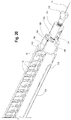
- Figure 1 shows a rear perspective view of the delivery device 2 with the handle assembly 8 while Figure 2 illustrates a side cross sectional view of the of the handle assembly 8.
- the handle assembly 8 includes a first or main handle 10 and second or outer handle 12.
- the main handle 10 is fixed relative to the delivery device 2.
- the second handle 12 is disposed on at least a portion of the main handle 10 and is movable longitudinally and/or circumferentially relative to the main handle 10.
- the main handle 10 comprises a proximal end 118 and a distal end 120 with an outer surface or side wall extending therebetween to form a handle interior 124.
- the handle interior 124 houses additional mechanical components that make up the handle assembly 8.
- the main handle 10 may be injection molded as a single unitary structure or alternatively, as shown in Figure 9 the main handle 10 may comprise upper and lower parts or first and second halves that clam shell, lock, snap-fit or are otherwise securable to each other.
- the proximal end 118 of the main handle 10 may include a gripping portion 126 for a physician to grip with one hand while manipulating the second handle 12 (such as during sheath retraction during deployment).
- the gripping portion 126 of the main handle 10 is preferably ergonomically shaped for user comfort, and may be covered in a layer of softer plastic or rubber or have a gripping surface to ensure a stable grip.
- the gripping portion 126 is a proximal portion 128 of the main handle that may have a greater diameter than the remainder of the main handle 10 which has a reduced diameter portion 130 and extends distally behind the gripping portion 126. It is the reduced diameter portion 130 of the main handle 10 upon which the second handle 12 can longitudinally move.
- At least a portion of the outer surface 122 of the main handle 10 includes partial or full threads 132 along its outer surface 122, which threads 132 extend distally from a location just distal of the gripping portion 126 to the handle end cap 14.
- a longitudinal slot 134 having a proximal end 136 and a distal end 138 is formed along a portion of the length of the main handle 10, between the gripping portion 126 and the handle end cap 14.
- the second handle 12 is located on the main handle 10.
- the second handle 12 may be a generally tubular structure that extends at least partially around the outer surface 122 of the main handle 10.
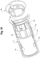
- the second handle 12 may be injection molded as a single unitary structure or alternatively, as shown in Figure 10 , the second handle 12 may comprise upper and lower parts or halves that clam shell, lock, snap-fit by snaps 141 or are otherwise securable to each other.
- the second handle 12 may further include an end cap 148.
- the end cap 148 may consist of two halves which can be attached together by various mechanisms such as snap fit, friction fit, corresponding engageable protrusions or by adhesives.
- the second handle 12 mechanically engages with the end cap 148 thereby preventing axial/longitudinal movement between the respective two parts but allows the second handle 12 to rotate independently from the end cap 148.
- one or more protrusions 160 such as a collar, thread or ring on the inner surface 140 of the second handle 12 may be engageable with a correspondingly shaped collar, protrusion, thread or ring on the end cap 148.
- the inner surface 140 of the second handle 12 may further comprise one or more structures, which engage with a mechanism such as a nut 142.
- the nut 142 is located within the second handle 12.
- the second handle 12 may comprise an opening or aperture 144 which engages with one or more radial protrusions 146 on the nut 142 (See Figure 31 ). As such, at least a portion of the inner surface 140 of the second handle 12 is engaged or otherwise operatively connected with the nut 142.
- any similar mechanisms or structures that allow the second handle 12 to engage with the nut 142 may be used.
- the nut 142 may be a cylindrical or tubular structure that completely encircles a portion of the main handle 10, or the nut 142 may partially cover or surround the main handle 10.
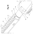
- the nut 142 may be a solid structure, or as shown in Figures 11 , 12 , 31 and 32 , a distal end 149 may be a solid structure or ring which encircles a portion of the main handle 10 while a proximal end 150 of the nut 142 may comprise a series of adjacent panels, fingers or flanges that extend proximally from the distal end 149 of the nut 142.
- the proximal end 150 of the nut 142 may flare radially outwardly in a neutral or relaxed state. (See Figure 11 and Figure 32 , for example). In a second radially inwardly compressed state, the inner surface of the nut 142 is configured to engage with an outer surface 122 of the main handle 10. (See Figure 31 , for example.)
- the second handle 12 may be rotated from its first proximal most position on the main handle 10 (as shown in Figures 1 and 14 ) to a second or an intermediate position ( Figure 16 and Figure 28 , for example) located between the proximal and distal ends 136, 138 of the longitudinal slot 134 formed in the main handle 10.
- Distal movement of the second handle 12 relative to the main handle 10 requires rotation of the second handle 12 when the inner surface 152 of the nut 142 within the second handle 12 is threadedly engaged with the outer surface 122 of the main handle 10. This threaded engagement necessitates rotation of the second handle 12 to impart longitudinal movement of the second handle 12 relative to the main handle 10.
- Rotation of the second handle 12 may be desired so as to provide more control and accuracy to the sheath retraction and proximal stent 46 placement and deployment (as shown in Figures 15 and 25 , for example).
- Figures 11 and 12 are perspective views of the handle assembly 8 shown with a portion of the second handle 12 removed, showing the second handle 12 in a first, proximal most position on the main handle 10.
- a ratcheted collar 154 is positioned under the second handle 12.
- the ratcheted collar 154 may fully or partially surround the main handle 10. As shown in Figure 11 , the ratcheted collar 154 extends distally from the gripping portion 126 of the main handle 10.
- the ratcheted collar 154 may be molded from a single unitary piece of material or may be multiple separately molded pieces ( i . e ., a collar portion 154a and a ratchet portion 154b) which are attached together such as by welding or glue.
- the ratcheted collar 154 may have one or more protrusions or teeth 156 that allow only for unidirectional rotation of the second handle 12.
- one or more protrusions 158 formed on the inner surface 140 of the second handle 12, or, alternatively a shim 158 positioned in a slot on the interior surface 140 of the second handle 12, as shown in Figure 10 engage with the ratcheted collar 154, so that the second handle 12 can rotate about the main handle 10 in one direction, while rotation of the second handle 12 about the main handle 10 in the opposite direction is prevented.
- the ratcheted collar 154 is preferably shaped so that the ratcheted collar 154 does not rotate relative to the main handle 10, but which allows the ratcheted collar 154 to slide longitudinally relative to the main handle 10.
- the cross sectional shape of the ratcheted collar 154 may be oblong or polygonal, have one or more flat sides or be irregularly shaped so that rotation of ratcheted collar 154 is prevented when the second handle 12 is rotated about the main handle 10, but which allows the ratcheted collar 154 to move longitudinally along the main handle 10 as the second handle 12 is moved distally by the user.
- the second handle 12 Before use of the delivery device 2 and when the delivery device is tracked to a desired location within a patient's body as shown in Figures 13 and 14 , the second handle 12 is disposed in a first or proximal most position on the main handle 10 and the stent graft 42 at the proximal end 4 of the delivery device 2 is fully sheathed and held in a radially inwardly contracted condition as shown in Figure 1 and 13A .
- the series of stents 50 on the main body of the stent 62 as well as the leg stents 72 are held in a radially inwardly contracted condition as shown in Figure 13A , which is an enlarged view of a portion of the sheathed stent graft 42 in Figure 13 .
- the protrusion 160 (such as a collar or ring on the inner surface 140 of the second handle 12) engages with a protrusion on the end cap 148 as shown in Figure 10 .
- the second handle 12 can rotate freely and independently of the end cap 148.
- the end cap 148 is pushed distally, which in turn pushes the sheath connector 108 distally, thereby also pulling the sheath 104 distally, to expose a proximal end 44 of the stent graft 42, such as the top stent 46 and seal stent 56 portions of the stent graft as shown in Figures 15 and 16 .
- Retracting the sheath 108 to expose a proximal end 44 of the stent graft 42, such as the top and seal stent 42, 56 may sometimes be referred to "exposing the diamond" by one of skill in the art.
- the longitudinal slot 134 formed in the main handle 10 accommodates the sheath flush port 116 on the sheath connector 108, such that as the second handle 12 is moved distally relative to the main handle 10, the sheath flush port 116 can slide distally along with the sheath connector 108 and the second handle 12 through this longitudinal slot 134 formed in the main handle 10.
- a prosthesis release actuation mechanism 162 By moving the second handle 12 distally relative to the main handle 10, a prosthesis release actuation mechanism 162, sometimes referred to herein as a "proximal suture drum 162" also becomes exposed and is now visible and accessible by the user as shown in Figure 16 .
- the proximal suture drum 162 is disposed about the main handle 10, just distal to the gripping portion 126 of the main handle 10 and just proximal to the nut 142.
- the proximal suture drum 162 is rotatable about the main handle 10.
- the second handle 12 when the second handle 12 is disposed in a first or proximal most position on the main handle 10 as shown in Figures 12 and 14 , the second handle 12 covers the proximal suture drum 162 so that the proximal suture drum 162 is not visible and cannot be accessed and/or manipulated (rotated) by the user.
- Figures 11 and 12 illustrate the second handle in a proximal most position on the main handle with a portion of the second handle 12 cut away to see the location of the proximal suture drum 162 hidden under the second handle 12.
- the proximal suture drum 162 may have one or more longitudinal grooves 164 on its outer surface (see Figures 12 and 18 ), which engage with one or more correspondingly shaped protrusions on the inner surface 140 of the second handle 12 to prevent premature or unintended rotation of the proximal suture drum 162 until the second handle 12 has been properly and sufficiently moved in a distal direction to expose the proximal suture drum 162. In other words, access to and rotation of the proximal suture drum 162 is prevented by the second handle 12 until an appropriate stage of a deployment sequence ( i .
- the second handle 12 has been retracted distally thereby withdrawing the sheath 104 a sufficient distance to expose at least the proximal end of the stent graft and deployment of the top stent 46 is appropriate and desired as described below).
- the prosthesis such as a stent-graft 42 disposed on the delivery device 2 at a stent-graft retention region 16 is fully covered by the retractable sheath as shown in Figures 1 and 13 .
- the main handle 10 may further comprise one or more radial protrusion(s) 168, such as a tooth or post.
- This protrusion 168 may be located just distal of the gripping portion 126 and is configured to engage with a ratchet 170 within the proximal suture drum 162 as shown in Figure 17 .
- the ratchet 170 within the proximal suture drum 162 may be integrally formed with at least a portion of an internal surface 172 of the proximal suture drum 162, or alternatively, the ratchet 170 may be a separate component that is connected or secured to the interior 172 of the proximal suture drum 162.
- a thin metal shim inserted within a radial slot formed in the wall of the inner surface 172 of the proximal suture drum 162 may serve as the ratchet that engages with the radial protrusion 168 extending from the outer surface 122 of the main handle 10.
- the ratchet 170 present on the inside 172 of the proximal suture drum 162 allows only for unidirectional rotation of the proximal suture drum 162.
- the ratchet 170 permits rotation of the proximal suture drum 162 in one particular direction, but prevents rotation of the proximal suture drum 162 in the opposite direction.
- the ratchet 170 may be configured so that it engages with the radial protrusion 168 on the main handle 10 to prevent counterclockwise rotation of the proximal suture drum 162, but permits clockwise rotation of the proximal suture drum 162.
- the components of the handle assembly 8, including the proximal suture drum 162 may be designed to rotate in any particular direction, however, as described herein for exemplary purposes, the ratchet 170 is configured to permit clockwise rotation of the proximal suture drum 162 and prevent counter-clockwise rotation.
- a motion translating mechanism 174 or distal suture drum 174, is disposed distal to the proximal drum 162 and is located within an end cap 14 at the distal end 120 of the main handle 10.
- the back end cap 14 may be a single structure or multiple parts or halves snap-fitted together and into engagement with the distal end 120 of the main handle 10.
- End cap 14 may have a distal taper 176 and may be removable or split open by the user should the need arise, such as in an emergency "bailout” procedure in the event that one or more components of the handle assembly 8 fail during deployment, thus allowing the user to remove the end cap 14 and access the handle interior 124, including the distal suture drum 174, to manually perform certain deployment steps described in further detail below.
- the inner cannula 22 extends distally through the back end cap 14 to the distal flush hub 24, as can be seen in Figure 19 .
- the distal suture drum 174 is operatively connected with the proximal suture drum 162.
- the distal suture drum 174 is disposed circumferentially around and connected to the inner cannula 22, such as by the pin vise 178, although other suitable mechanisms for attaching the inner cannula 22 to the distal suture drum 174 are also contemplated, including adhesives, for example.
- the distal suture drum 174 is configured to rotate the inner cannula 22 to effect the release of the prosthesis 42 from the prosthesis retention mechanism 80.
- the proximal suture drum 162 (e . g . the prosthesis release actuation mechanism) is operatively connected to the distal suture drum 174 ( e.g ., the motion translating mechanism) by an elongated filamentous material 180, such as a suture, string, wire, cord, thread and the like.
- the suture 180 may be composed of ultra-high molecular weight polyethylene (UHMWPE); alternatively, a nitinol wire or other suitable materials may be utilized.
- UHMWPE ultra-high molecular weight polyethylene
- the suture 180 serves to transfer motion of the proximal suture drum 162 to the distal suture drum 174.
- the suture 180 is pre-wound around the distal suture drum 174 at a suture-wrapping portion 182 a select number of times and secured to the distal drum 174, such as via a set screw 184 and/or a 4-40 screw thread.
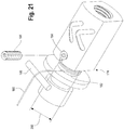
- the suture 180 then extends from where it is wrapped around the suture wrapping portion 182 of the distal suture drum 174 over/around a pin 186 extending generally perpendicularly to the longitudinal axis of the main handle 10.
- each end of the pin 186 is held within an opening or slot 188 formed in the distal end 120 of the main handle 10.
- the suture 180 After wrapping up and over the pin 186, the suture 180 extends longitudinally forward or proximally through a small suture cannula 190 that is embedded in a sidewall of the main handle 10 or which extends longitudinally through the main handle 10 generally parallel to an inner surface 124 of the main handle 10.
- the suture 180 then exits the suture cannula 190 at a proximal location 192 on the main handle 10 adjacent to where the proximal suture drum 162 sits on the main handle 10, as shown in Figure 22 .
- the suture 180 exits the suture cannula 190 and is connected to the proximal suture drum 162.
- the inner surface 172 of the proximal suture drum 162 has an attachment surface, such as a "J" peg and/or post 194 around which the suture 180 may be wrapped one or more times and then secured to the proximal suture drum 162 by a set screw 196. It is also contemplated that the suture 180 can be secured to the proximal suture drum 162 by other suitable attachment mechanisms, such as being threaded through an opening or aperture, tied, crimped and/or secured by adhesives or a combination thereof.
- the proximal suture drum 162 When the proximal suture drum 162 is rotated (such as in a clockwise direction as indicated in Figure 26 ) the suture 180 connected to the inner surface 172 of the proximal suture drum 162 starts to wind around a proximal portion 198 of the outer surface 122 of the main handle 10 as shown in Figures 9 and 22 (where the proximal suture drum 162 has been removed to show the detail and location of the suture 180 wrapping around proximal portion 198 of the main handle 10).
- the proximal portion 198 of the main handle 10 on which the suture 180 is wound may be smooth or bare, or alternatively, it may be threaded so that the suture 180 is wound in parallel loops so there is no overlap.
- Rotation of the proximal suture drum 162 by the user winds the suture 180 around the outer surface 122 of the main handle 10, and simultaneously, the suture 180 unwinds from the distal suture drum 174.
- the proximal end of the suture 180 winds around proximal portion 198 of the main handle 10
- the distal end of the suture 180 unwinds from the distal suture drum 174, thus causing the distal suture drum 174 to rotate.
- the inner cannula 22 rotates along with it.
- the rotation of the distal suture drum 174 at the distal end 120 of the handle assembly 8 causes the inner cannula 22 to rotate along its entire length.
- Rotation of the inner cannula 22 along its entire length effects release of the prosthesis retention mechanism 80 from the proximal end 44 of the stent graft 42, such that the prosthesis retention mechanism moves from a prosthesis capture condition to a prosthesis release condition, as will be described below.
- the diameter 200 of the proximal suture wrapping portion 198 of the main handle on which the proximal drum 162 sits (and upon which the suture 180 becomes wrapped during use) may determine the diameter 202 ( Figure 21 ) of the distal suture wrapping portion 182 of the distal suture drum 174 upon which the suture 180 is wrapped.
- a user grips and/or re-grips a rotating part, such as the proximal suture drum, three times to enable one complete 360 degree rotation of the proximal suture drum 162.
- the cannula 22 needs to rotate approximately 3-4 times ( i . e ., 3-4 complete revolutions if considering tortuous anatomy) to safely release the top stent 46.
- one complete rotation of the proximal suture drum 162 preferably causes 3-4 rotations of the distal suture drum 174, which may be accomplished by making the distal suture drum diameter 202 upon which the suture 180 wraps approximately 3-4 times smaller than the diameter 200 of the proximal suture wrapping portion 198.
- n 3 or 4 rotations of the inner cannula .
- the user may continue to rotate the second handle 12 to further move the second handle 12 distally along the main handle 10 to further retract the sheath 104 and expose the main body 62 of the stent graft 42 and, depending on the length of the contralateral limb 58, also expose at least a portion of the contralateral limb 58 as shown in Figure 23 and Figure 24 .
- the second handle 12 may only need to be moved distally on the main handle 10 to a position such as that shown in Figure 23 and the contralateral limb 58 may be fully exposed.
- the second handle 12 must be moved distally on the main handle 10 as far back as the distal trigger wire knob 204 in order to fully un-sheath and expose the contralateral limb 58 as shown in Figure 26 .
- the second handle 12 may continue to move distally until the distal end 14 of the sheath connector 108 within the second handle 12 and/or the end cap 148 touches, meets, abuts or is otherwise adjacent to a distal trigger wire knob 204 located within the main handle interior 124, as shown in Figures 26 and 28 .
- the user may feel a slight resistance which signals that the sheath connector 108 has reached the distal trigger wire knob 204.
- Other visual or mechanical signals may also be present on the delivery device 2 and/or handle assembly 8 to indicate to the user to stop rotating the second handle 12 (to thereby stop further distal movement of the second handle 12 along the main handle 10) including visual cues provided by desired imaging modality ( i .
- the top stent 46 may be released as shown in Figure 25 by rotating the proximal suture drum 162 as shown in Figure 26 .
- release of the top stent 46 may be accomplished by clockwise rotation of the proximal suture drum 162.
- Rotation of the proximal suture drum 162 which is operatively connected to the distal suture drum 174 via the suture 180, thereby effects rotation of the inner cannula 22 (including the prosthesis retention mechanism 80 at the proximal end of the cannula 22) to enable release of the top stent apices 66 or loops 74 captured by the coil or helix 84, as shown in Figures 4 and 5 .
- the components of the handle assembly 8, including the proximal suture drum 162, distal suture drum 174 and/or inner cannula 22 (including the prosthesis retention mechanism 80 or coiled member 84) may be designed, manufactured and assembled to rotate in any particular direction (clockwise and/or counterclockwise). Any particular direction as described and designated herein is for exemplary purposes only and should not be considered so limiting.
- the proximal suture drum 162 may be rotated clockwise, but the direction that the distal suture drum 174 rotates may depend on how the suture 180 is pre-wound on the distal suture drum 174 (either clockwise wound or counter-clockwise wound).
- rotation of the proximal suture drum 162 ( i .
- the prosthesis release actuation mechanism in a first direction effects rotation of the distal suture drum 174 ( i . e ., the motion translating mechanism) in a second direction and wherein rotation of the distal suture drum 174 ( i . e ., the motion translating mechanism) effects rotation of the inner cannula 22 and the coiled member 84 ( i . e ., the prosthesis retention mechanism 80) in a third direction.
- the first, second and third directions may be the same, or the first, second and third directions may be different, or a combination thereof.
- the proximal suture drum 162 may be rotated clockwise by the user, and the suture pre-wrapped upon the distal suture drum 174 in a clockwise direction, which, when unwound from the distal suture drum 174, rotates the distal suture drum 174 in a clockwise direction thereby rotating the inner cannula 22 in a clockwise direction.
- the proximal suture drum 162 may be designed and assembled for counterclockwise rotation, as can the distal suture drum 174 and/or inner cannula 22.
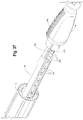
- the second handle 12 can then be moved further distally relative to the main handle 10 (from the position shown in Figures 23 , 26 and 28 ) to a final or distal most position on the main handle 10 (as shown in Figure 29 ) to further retract the sheath 104 while simultaneously withdrawing one or more distal trigger wires to thereby deploy the ipsilateral limb 60 of the stent graft 42 as shown in Figure 27 .
- This final distal movement of the second handle 12 to a position on the main handle 10 may be accomplished by the user continuing to rotate the second handle 12 relative to the main handle 10 as described above, where rotation of the second handle 12 causes the second handle 12 to travel distally in a longitudinal direction along the main handle 10.
- the user has the option to implement a "quick release" protocol in order to retract the second handle 12 distally without rotation, as will be described in further detail below.
- the distance of travel of the second handle 12 relative to the main handle 10 to this final or distal most position is identified as reference number 210 in Figure 29 .
- distal movement of the second handle 12 from a second or an intermediate position in Figure 28 to the distal most position in Figure 29 causes the sheath connector 108 to retract distally (thereby retracting the sheath 104 distally) to expose the ipsilateral limb 60 of the stent graft 42.
- the distal end of the second handle 12 and/or the distal end 114 of the sheath connector pushes against a distal trigger wire release mechanism 204 located within the main handle 10.
- the distal trigger wire release mechanism 204 is a ring that is slidably disposed over the positioner 30.
- One or more distal trigger wire(s) 208 extend proximally from the distal trigger wire release mechanism 204 to the distal end of the stent-graft 48.
- the positioner 30 provides a conduit for the distal trigger wires 208 to extend from the trigger wire release mechanism 204 in the main handle 10 to the distal end 48 of the stent graft 42.
- one or more trigger wires 208 may be secured to the distal trigger wire release mechanism 204 by a set screw 214.
- the trigger wire 208 then extends from the trigger wire release mechanism 204 and into an opening, hole or aperture 216 formed in the positioner 30, where the distal trigger wire(s) 208 further extend proximally through the conduit provided by the positioner 30 to the distal end 48 of the stent graft 42.
- a seal 218, such as a silicone sleeve or disc may be provided to cover the hole 216 formed in the positioner 30 and prevent back-leakage of fluids through the hole 216.
- the distal trigger wire(s) 208 may be directly or indirectly attached to the distal end 48 of the stent graft 42.
- the distal trigger wires 208 may engage a suture (not shown) which is attached to the distal end 48 of the ipsilateral limb 60 of the stent-graft 42.
- the distal trigger wire 208 may be woven directly through or removably attached to the graft material 52 or one or more stents 72 at the distal end of the graft 42.
- Other suitable attachment methods or mechanisms may be used to removably attach the distal trigger wires 208 to the distal end of the stent graft 42 as would be recognized by one of skill in the art.
- distal movement of the second handle 12 pushes or drives the distal trigger wire knob 204 distally with it, thereby pulling the one or more distal trigger wires 208 in a distal direction.
- the proximal end of the distal trigger wire(s) 208 thereby are withdrawn or become disengaged from the distal end of the stent graft 42 ( i . e ., the distal trigger wires 208 become released from the suture loop and/or become disengaged from the graft material 52 at the distal end of the ipsilateral limb 60).
- Distal movement of the second handle 12 ceases upon second handle 12 reaching the distal end 138 of the longitudinal slot 134 formed in the main handle 10 and/or when the distal trigger wire knob 204 abuts or contacts the stationary collar 36 at the distal end 120 of the main handle 10.
- second handle 12 can rotate about the longitudinal axis of the main handle 10 to move the second handle 12 distally, thus retracting the sheath 104 to expose the proximal stent 46, the main body 62 and the contralateral limb 58 of the stent graft 42 as shown in Figure 24 .
- the threaded engagement between the inner surface 152 of the nut 142 and outer surface 122 of the main handle 10 necessitates rotation to impart longitudinal movement of the second handle 12 relative to the main handle 10.
- the user may continue to rotate the second handle 12 to move it distally to further retract the sheath 104 to expose the ipsilateral limb 60 and release the trigger wires 208 from the distal end of the stent graft 42 during deployment.
- the "quick release" procedure may now be employed at this stage of deployment, if desired, in order to further retract the sheath 104 to expose the ipsilateral limb 60 and to release the distal trigger wires 208 without having to rotate the second handle 12 relative to the main handle 10.
- the "quick release" procedure provides the user the ability to slide the second handle 12 freely longitudinally along the main handle 10 without rotation in a straight pull-back motion, so that the second handle 12 can simply slide longitudinally along the main handle 10 in a continuous smooth non-rotating motion.
- This provides several advantages, including, for example, the user being able to retract the second handle 12 more quickly and without rotation to complete sheath retraction and distal trigger wire removal.
- the user can firmly grip the gripping portion 126 of the main handle 10 with one hand while pulling back on an outer ring 220 located on the second handle 12 with the other hand as Figure 28 shows to "release” or disengage the second handle 12 from the main handle 10, thus allowing the second handle 12 to slide freely longitudinally along the main handle 10 without rotation in a straight pull-back motion.
- the nut 142 located within the second handle 12 extends at least partially circumferentially around at least a portion of the main handle 10.
- the inner surface of the nut 142 is engaged with threads 132 on the outer surface 122 of the main handle 10 by a threaded engagement, although other mechanisms may be used to provide engagement between the nut 142 and the main handle 10.
- the second handle 12 With the inner surface 152 of the nut 142 engaged with the outer surface 122 of the main handle 10, the second handle 12 must be rotated in order to move the second handle 12 distally along the main handle 10 (such as during the previously-described steps of moving the second handle 12 distally to facilitate sheath retraction and proximal stent deployment.)
- a sleeve 222 extends at least partially circumferentially over and/or around the nut 142, or alternatively, the sleeve 222 may completely surround or enclose a portion of the outer surface of the nut 142.
- the sleeve 222 may be a curved, arcuate and/or semi-circular structure that is positioned on the outer surface of the nut 142, as shown in Figure 31 A .
- the outer surface of the sleeve 222 may have one or more radially outwardly extending protrusions 224 that extend through one or more openings or slots 226 formed in the second handle 12 (see Figure 10 ) so as to engage with an opening or channel formed in the inner surface of the ring 220.
- Any other suitable mechanisms and/or correspondingly shaped structures on the sleeve 222 that are configured to allow the sleeve 222 to connect to or operatively engage with the ring 220 may also be used as would be recognized by one of skill in the art.
- the sleeve 222 When the ring 220 is in a first or proximal position relative to the second handle 12 as shown in Figure 31 , the sleeve 222, which is operatively engaged with the ring 220 as previously described, is also positioned at a proximal end of the nut 150.
- the sleeve 222 holds the proximal end 150 of the nut 142 in a radially inwardly compressed condition and prevents such outward flaring of the nut 142.
- the sleeve 222 maintains and/or urges the nut 142 radially inwardly and the urges the threads on the inner surface 152 of the nut 142 into engagement with the outer surface 122 of the main handle 10.
- the ring 220 is moved from the first proximal position to a second distal position (shown in Figure 32 ) by the user to move the sleeve 222 distally relative to the nut 142.
- a second distal position shown in Figure 32
- the proximal end 150 of the nut 142 is permitted to expand radially outwardly so that the inner surface 152 of the nut 142 is released from engagement with the main handle 10.
- the nut 142 is self expanding, such that when the sleeve 222 is moved distally, the proximal end 150 of the nut 142 may expand radially outwardly without the aid or assistance of mechanical expansion techniques because the proximal end 150 of the nut 142 may have a tendency to flare radially outwardly in a natural or relaxed position.
- the nut 142 may also be mechanically expanded.
- the proximal portion 228 of the sleeve 222 includes an expanding structure 230 that is configured to engage with at least a portion of the inner surface 152 of the nut 142 and urge the proximal end 150 of the nut 142 radially outwardly.
- the expanding structure 230 comes into contact with the proximal end 150 of the nut 142 to radially outwardly expand the proximal end 150 of the nut 142.
- the inner surface 152 of the nut 142 thus becomes disengaged from the main handle 10 allowing the second handle 12 to be moved distally along the main handle 10 without rotation.
- the expanding structure 230 may be in the form of a ring, partial ring, semi-circle, wedge and/or any other structure that facilitates radial expansion of the nut 142. As shown in Figures 31, 31 A and 32 , the expanding structure 230 is a semi-circular structure that is located just proximal to and connected to the sleeve 222. The expanding structure 230 has a radius that is smaller than the radius of the sleeve 222. When the ring 220 is pulled distally back, the sleeve 222 with the expanding structure 230 also moves distally back.
- the expanding structure 230 drives itself between the outer surface 122 of the main handle 10 and the inner surface 152 of the proximal end 150 of the nut 142, thus urging the proximal end 150 of the nut 142 in a radially outwardly expanded condition.
- the expanding structure 230 will facilitate the radially outward expansion of the proximal end 150 of the nut 142 to disengage the nut 142 from the main handle 10, allowing the quick release procedure to still be utilized.
- a self-expanding nut 142 may fail to sufficiently expand or become deformed so that it cannot fully disengage from the main handle 10 because of age and/or sterilization, for example.
- the expanding structure 230 serves to facilitate the radially outward expansion of the proximal end 150 of the nut 142 during the quick release procedure.
- the action of sliding outer ring 220 distally may also make visible an arrow (or set of arrows or other similar markings) on the second handle 12 which serve as an indicator to the user that the second handle 12 is ready for "quick release" by straight distal pull-back of the second handle relative to the main handle 10.
- an arrow or set of arrows or other similar markings
- the second handle 12 is disengaged from the main handle 10 and can be slid distally towards the user (without rotation) so that further retraction of the sheath 104 to expose the ipsilateral limb 60 can be completed while simultaneously withdrawing the distal trigger wire(s) 208 to fully release the stent graft in the vasculature as shown in Figure 27 , thus accomplishing a "quick release" portion of the procedure.
- the handle assembly 8 further comprises a notched or threaded rack-like mechanism 232 which engages with the proximal suture drum 234.
- the rack 232 has a proximal end 236 and a distal end 238, and has threads 240 formed on at least a portion of the rack's outer surface extending between the proximal and distal ends 238.
- the rack 232 is located inside the main handle 10 near the proximal end of the main handle 10.
- a slot or channel 242 formed in the proximal end 118 of the main handle 10 allows the rack 232 to travel longitudinally in a proximal direction inside the main handle 10.
- the proximal end of the suture 180 is secured to or otherwise connected to the rack 232 as shown in Figures 35 and 36 .
- the suture 180 may be secured to the distal end 238 of the rack 232 via a J post or set screw 246, or alternatively or in combination, the suture 180 may be threaded or tied around or through an aperture or slot 244 formed in the distal end 238 of the rack 232 and/or secured to the rack with adhesives or other suitable attachment mechanisms.
- the threads 240 on the outer surface of the rack 232 are engageable with threads 248 formed on the inner surface of a proximal suture drum 234, shown in Figure 38 .
- proximal suture drum 234 When the proximal suture drum 234 is rotated, threads 248 on the inner surface of the proximal suture drum 234 engage with the threads 248 on the rack 232, thus pulling or moving the rack 232 longitudinally in a proximal direction. As the rack 232 moves longitudinally in a proximal direction, the rack 232 thereby pulls the suture 180 proximally along with it, thus pulling the suture 180 off the distal suture drum 174. As the suture 180 is pulled off the distal suture drum 174, the distal suture drum 174 rotates, and in turn, rotates the inner cannula 22 along its entire length. In the same manner as already described in detail above, rotation of the inner cannula 22 causes the prosthesis retention mechanism 80 to release the prosthesis 42 carried at the proximal end 4 of the delivery device 2.
- the rack 232 may further include one or more protrusions, fingers or teeth.
- the protrusions 250 may be angled relative to a central or longitudinal axis of the rack 232 as shown in Figure 35 .
- a portion of the inner surface 124 of the main handle 10 may comprise one or more correspondingly shaped and/or angled protrusions or teeth 252 as shown in Figures 33 and 35 .
- the angle of the teeth 252 on the inner surface of the main handle 10 are such that they permit the rack 232 to move proximally forward within the main handle 10 as the user rotates the proximal suture drum 234, however, the angle and/or shape of the teeth 252 on the inner surface of the handle do not permit the rack 232 to move distally backwards within the main handle 10.
- the user may grip the proximal suture drum 234 and begin to rotate the proximal suture drum 234, thus pulling the rack 232 proximally within the main handle 10 and causing the suture to unwind from the distal suture drum 174.
- the rack 232 would not automatically revert or slide back or distally within the main handle 10 to its initial position which may be present due to, for example, tension in the distal suture drum 174 tending to pull the suture 180 (as well as the rack 232) backwards or distally.
- the engagement between the protrusions 250 on the rack 232 and the teeth 252 on the inner surface of the main handle 10 will serve to maintain the proximal travel progress of the rack 232, and will not allow the rack 232 to slide or drift distally back within the main handle 10.
- Maintaining the proximal travel progress of the rack 232 thereby also maintains the number of rotations achieved by the distal suture drum 174 as well as the number or rotations of the inner cannula 22.
- the user can be confident that the number of rotations accomplished by the inner cannula 22 to release the prosthesis retention mechanism (coil 84) at the proximal end 4 of the device 2 cannot unknowingly or unwittingly become "undone" because the rack 232 and suture 180 cannot revert or travel distally backwards within the main handle 10 to thereby rotate the distal suture drum 174 and inner cannula 22 in an unwanted reverse direction and possibly tangle the coil 84 with the proximal apices 66 or loops 74 of the stent graft 42.
- the suture 180 is not directly attached to the proximal suture drum 234, therefore, rotation of the proximal suture drum 234 by the user does not cause the suture 180 to wrap around an outer surface 198 of the main handle 10 as in the previously described embodiment (see Figures 17 and 22 , where the suture 180 is attached to the proximal suture drum 162 for wrapping the suture 180 around the main handle 10 at portion 198).
- the proximal suture drum 162 engages directly with the rack 232.
- the proximal suture drum 162 includes threads 248 on its internal surface, such that rotation of the proximal suture drum 162 by the user engages threads 240 on the rack 232 thereby pulling or urging the rack 232 forward or proximally, thereby pulling the suture 180 proximally (because the suture 180 is connected to the distal end 238 of the rack 232).
- proximal movement of the suture 180 due to rotation of the proximal suture drum 234 and unwinding of the suture 180 from the distal suture drum 174 to impart rotation to the distal suture drum 174 and to the inner cannula 22 to effect release of the prosthesis retention mechanism 80 remains substantially the same.
- the delivery device 2 and in particular the handle assembly 8 of the delivery device 2, will be described.
- use of the delivery device 2 will be described in reference to the implantation of a stent-graft 42, such as the one shown in Figure 3 in an aorta 254 of a patient.
- the nose cone dilator 18 is inserted into the incision and the device 2 is tracked over a guide wire 28 and advanced through the artery to the desired location, for example the abdominal aorta 254 for placement of the stent-graft 42 at the site of an aneurysm, with the atraumatic tip 20 of the nose cone dilator 18 reducing the likelihood of injury to bodily passageways.
- the outer sheath 104 is disposed over the stent-graft 42 during insertion and delivery to the target site, as shown in Figures 1 and 13 .
- a mechanism such as the pin vise 178 may be used to prevent longitudinal/ axial movement of the inner cannula 22 during delivery to target location.
- the user grasps the gripping portion 126 of the main handle 10 with one hand, and using the other hand, grasps the second handle 12.
- the second handle 12 may be rotated relative to the main handle 10 to move the second handle 12 distally along the main handle 10, thereby retracting the sheath 104 to expose at least a proximal portion of the stent-graft 42.
- the user may retract the sheath 104 to expose the top and/or seal stents 46, 56, sometimes referred to as the exposing the "diamond" at this stage of deployment as shown in Figure 15 .
- the second handle 12 has been moved distally a sufficient distance such that the proximal suture drum 162 is also accessible and visible to the user (see Figure 16 ).
- the user may continue to move the second handle 12 distally (such as by rotating the second handle 12 relative to the main handle 10) to further retract the sheath 104 until at least a portion of the contralateral limb 58 is exposed as shown in Figure 24 .
- the proximal end 144 of the stent 42 may be deployed.
- the user may rotate the proximal suture drum 162, which winds the suture 180 around a proximal portion 198 of the outer surface of the main handle 10 (or in an alternative embodiment, rotation of the proximal suture drum 234 engages the rack 232, which pulls the rack 232 proximally forward within the main handle 10) which in turn, pulls the suture 180 proximally to unwind the suture 180 from the distal suture drum 174.
- the unwinding of the suture 180 from the distal suture drum 174 causes the distal suture drum 174 to rotate.
- Rotational motion of the distal suture drum 174 is transferred (by the suture 180) to the inner cannula 22, causing the entire length of the inner cannula 22 to rotate as shown in Figure 26 .
- Rotation of the inner cannula 22 effects release of the prosthesis retention mechanism 80.
- the proximal apices 66 or suture loops 74 of the stent graft 42 are uncoupled from the coiled member 84 ( i .
- a second guide wire 256 may be tracked through the contralateral leg 58 and main body 62 of the stent graft 42, to cannulate the contralateral leg 58.
- a second leg extension stent graft 258 can be fed over the guide wire 256 and into position within the cannulated contralateral leg 58 as shown in Figure 25 .
- the second handle 12 may again be moved back in a distal direction relative to the main handle 10 by the user as shown in Figure 29 to further retract the sheath 104 while simultaneously withdrawing one or more distal trigger wires 208 to thereby deploy the ipsilateral limb 60 of the stent graft 42 as shown in Figure 27 .
- the user may continue rotation of the second handle 12 or, alternatively, the user may employ the "quick release” procedure, which permits longitudinal movement of the second handle 12 relative to the main handle 10, without having to rotate the second handle 12, to thereby retract the sheath 104 and remove the distal trigger wires 208.
- the user moves the second handle 12 distally along the main handle 10 for a travel distance indicated by reference number 212 in Figure 28 .
- this travel distance 212 may be the distance of longitudinal movement of the second handle 12 necessary to facilitate distal retraction of the sheath 104 a sufficient distance to completely un-sheath the ipsilateral limb 60 of the stent graft 42.
- the distal trigger wire or wires 208 are also withdrawn from the distal end 48 of the prosthesis 42 to complete the stent graft deployment.
- the handle end cap 14 can be removed, and the interior 124 of the main handle 10, including the distal suture drum 174 can be accessed and rotated manually.
- the nut 142 has already been disengaged or disassociated from the main handle 10, allowing the second handle 12 to slide freely longitudinally along the main handle 10.
- the user can slide the second handle 12 in a proximal direction (away from the user) on the main handle 10, thus sliding the sheath connector 108 and sheath 104 proximally and allowing the proximal end of the sheath 104 to extend over all of, part of, or at least distal portion 82 of the nose cone 18 of the device 2 so as to "hub" or "recapture” a portion of the nose cone within the sheath 104.
- the main handle may be pulled distally relative to the second handle 12, thus pulling the distal portion 82 of the nose cone 18 into the proximal end of the sheath 104. With at least a distal end of the nose cone 18 recaptured within the sheath 104, the delivery device 2 can be withdrawn from the patient's body.
- the second handle 12 is at a distal most position on the main handle (see Figure 29 ) but the inner surface of the nut 142 is still threadedly engaged with the outer surface 122 of the main handle 10.
- the user in order to move the second handle 12 proximally for tip re-sheathing or recapture, the user must first move the ring 220 distally on the second handle 12 to move the sleeve 222 distally, allowing the proximal end 150 of the nut to flare or expand radially outwardly and disengage from the threads 132 on the main handle 10.
- This permits the second handle 12 to now slide freely longitudinally on the main handle 10 and the user may then be able to move the second handle 12 proximally to recapture (re-sheath) the proximal tip as previously described , and then remove the delivery device 2 from the patient to complete the procedure.
Description
- The present invention relates to a deployment handle for a delivery device for a prosthesis such as a stent graft, and to a delivery device including such a handle.
- The use of delivery devices or introducers employing catheters has long been known for a variety of medical procedures, including procedures for establishing, re-establishing or maintaining passages, cavities or lumens in vessels, organs or ducts in human and veterinary patients, occlusion of such vessels, delivering medical treatments, and other interventions. For these procedures, it has also long been known to deliver an implantable medical device by means of a catheter, often intraluminally. For example, a stent, stent-graft, vena cava filter or occlusion device may be delivered intraluminally from the femoral artery for deployment.
A variety of delivery devices are known in the art. For instance,US6,709,667B concerns delivery systems for contraceptive devices, specifically those to deploy contraceptive devices transcervically into an ostium of a fallopian tube. According to the document, the contraceptive device may remain in a small profile configuration while a sheath is withdrawn proximally, and is thereafter expanded to a large profile configuration engaging the surrounding tissues, by manipulating one or more actuators of a proximal handle with a single hand. This leaves the other hand free to manipulate a hysteroscope, minimizing the number of health care professional required to deploy the contraceptive device.
Reference is additionally directed toUS2006/136034A1 , which discloses a delivery catheter that includes a first, flexible, polymer-based tube and a second, metal tube at the first tube distal end. The second tube has flexibility enhancing relief areas along its length to provide localized areas of reduced bending stiffness to enhance the bending flexibility while retaining good torsional stiffness. A notched catheter has a lumen and a notched outer surface intersecting the lumen with a filament-containing layer adjacent to the outer surface. A part of the filament-containing layer is capturable between the notched surface portion and an elongate element extendable through the lumen. A generally helically coiled endoluminal prosthesis may be mounted on a pre-torqued delivery catheter to tighten the coiled endoluminal prosthesis onto the delivery catheter. In one embodiment, there is provided a handle that can be operated to simultaneously rotate the delivery catheter and retrieve a release wire.
Reference is further directed toUS2002/0151956A1 , which discloses a flexible low profile delivery system for delivery of an expandable intracorporeal device, specifically, an endovascular graft, which has at least one belt circumferentially disposed about the device in a constraining configuration. The belt is released by a release member, such as a release wire, by retracting the wire from looped ends of the belt. According to the document, multiple belts can be used and can be released sequentially so as to control the order of release and placement of the endovascular graft. An outer protective sheath may be disposed about the endovascular graft while in a constrained state which must first be retracted or otherwise removed prior to release of the graft from a constrained state. The delivery system can be configured for delivery over a guiding device such as a guidewire.
Reference is still further directed toUS2011/0288558A1 , which discloses a handle for an implant deployment device that converts rotational movement into longitudinal movement in order to provide controlled release of one or more trigger wires. The handle also allows the trigger wire to be withdrawn into the device so that it does not need to be separately removed. A preferred handle includes a rotatable portion and a slidable portion. Releasable locks ensure that the handle is used to carry out implant deployment steps in a specific order.
For procedures in which a prosthesis or other medical device is implanted into a patient, the prosthesis to be implanted is normally held on a carrier catheter or cannula of the introducer in a compressed state and then released from the carrier catheter so as to expand to its normal operating state, prior to withdrawal of the catheter from the patient to leave the prosthesis in position. In many devices, the steps to carry out the implantation my occur, for example, first by retracting a retractable sheath to expand or partially expand the prosthesis, and then performing further steps to, for example, release one or both ends of the prosthesis, deploy an anchoring stent, or the like. In most cases, it is desirable that such deployment steps follow a specific order as instructed by the manufacturer of the device, but the user of the device is often not restricted from performing steps out of order, and often may do so. Thus, it is desirable to provide a delivery device having a handle assembly that permits controlled and sequential release and deployment of a prosthesis from the delivery device. - The invention is defined in the appended claims.
- The following disclosure relates to a deployment handle assembly for a delivery device for a prosthesis such as a stent graft, to a delivery device including such a handle assembly and a method for deploying a stent graft using a device having such a handle assembly. In one example, a handle assembly for a prosthesis delivery device having a proximal and distal end is disclosed. The handle assembly comprises a main handle having a proximal end and a distal end. A prosthesis release actuation mechanism is disposed at least partially on the main handle and moveable relative to the main handle. A motion translating mechanism is disposed distal to and operatively connected to the prosthesis release actuation mechanism. A prosthesis retention mechanism disposed at the proximal end of the delivery device and operatively connected to the motion translating mechanism. The prosthesis retention mechanism has a prosthesis capture condition and a prosthesis release condition. Movement of the prosthesis release actuation mechanism causes movement of the motion translating mechanism thereby moving the prosthesis retention mechanism from the prosthesis capture condition to the prosthesis release condition.
- A handle assembly for a prosthesis delivery device having a proximal end and a distal end is also described. The handle assembly may comprise: a main handle having a proximal end and a distal end; a prosthesis release actuation mechanism disposed at least partially on the main handle and moveable relative to the main handle; and a motion translating mechanism disposed distal to and operatively connected to and, optionally, disposed distal to the prosthesis release actuation mechanism. The motion translating mechanism may be operatively connected to a prosthesis retention mechanism disposed at the proximal end of the delivery device. The prosthesis retention mechanism may have a prosthesis capture condition and a prosthesis release condition; movement of the prosthesis release actuation mechanism may cause movement of the motion translating mechanism thereby moving the prosthesis retention mechanism from the prosthesis capture condition to the prosthesis release condition. The main handle may have a longitudinal direction extending between its proximal end and distal end.
- The prosthesis release actuation mechanism may be circumferentially disposed about the main handle and rotationally moveable relative to the main handle. Optionally, the prosthesis release actuation mechanism is configured such that rotation is restricted to one sense. Optionally, the prosthesis release actuation mechanism may be rotationally moveable about an axis parallel to the longitudinal direction of the main handle. In one example, rotation of the prosthesis release actuation mechanism may effect rotation of the motion translating mechanism, such rotation being, for example, about an axis parallel to the longitudinal direction of the main handle. Optionally, the axis of rotation of the prosthesis release actuation mechanism may be the same as that of the motion translating mechanism; for instance, both may be rotatable about the longitudinal axis of the main handle. In a particular example, rotation of the prosthesis release actuation mechanism may effect rotation of the motion translating mechanism at a different angular rate, for example at a higher angular rate (for instance, rotation of the prosthesis release actuation mechanism by two turns may cause the motion translating mechanism to rotate by four turns).
- A prosthesis delivery device is also described. In one example, the delivery device has a proximal end and distal end, and a handle assembly at the distal end. The handle assembly comprises a main handle having a proximal end and a distal end and a prosthesis release actuation mechanism disposed at least partially on the main handle and moveable relative to the main handle. A motion translating mechanism is disposed distal to and operatively connected to the prosthesis release actuation mechanism. A prosthesis retention mechanism is disposed at the proximal end of the delivery device and operatively connected to the motion translating mechanism, The prosthesis retention mechanism has a prosthesis capture condition and a prosthesis release condition. Movement of the prosthesis release actuation mechanism causes movement of the motion translating mechanism thereby moving the prosthesis retention mechanism from the prosthesis capture condition to the prosthesis release condition. The delivery device may have a longitudinal direction extending between its proximal end and distal end.
- The motion translating mechanism may be rotatable. For example, rotation of the motion translating mechanism may effect rotation of the prosthesis retention mechanism. Optionally, the axis of rotation of the motion translating mechanism may be the same as that of the prosthesis retention mechanism; for instance, both may be rotatable about the longitudinal axis of the delivery device. In a particular example, rotation of the motion translating mechanism may effect rotation of the prosthesis retention mechanism at a different angular rate, for example at a higher angular rate (for instance, rotation of the motion translating mechanism by two turns may cause the prosthesis retention mechanism to rotate by four turns).
- In another example, a method for sequentially releasing a prosthesis from a delivery device is described. The delivery device comprises a rotatable inner cannula extending from a proximal end to a distal end, a prosthesis releasably coupled to the proximal end of the inner cannula, a sheath coaxially disposed about at least a portion of the prosthesis and a delivery handle assembly at a distal end of the delivery device. The delivery handle assembly comprises a main handle, a second handle disposed at least partially on the main handle and at least one of circumferentially and longitudinally moveable relative to the main handle and a prosthesis release actuation mechanism disposed at least partially on the main handle. In one example, the method comprises manipulating the second handle from a first position on the main handle to a second position on the main handle to retract the sheath thereby exposing at least a proximal end of the prosthesis and to permit actuation of the prosthesis release actuation mechanism. The method further comprises actuating the prosthesis release actuation mechanism to deploy at least the proximal end of the prosthesis and manipulating the second handle from the second position to a third position on the main handle to further retract the sheath to expose a distal end of the prosthesis.
-
-
Figure 1 is a perspective view of a prosthesis delivery device with an example of a handle assembly at the distal end and a prosthesis retained beneath a sheath at the proximal end. -
Figure 2 is a side cross sectional view of the handle assembly ofFigure 1 . -
Figure 3 is an exemplary stent graft that may be delivered and deployed within the vasculature of a patient. -
Figure 4 is a side view of the proximal end of the delivery device with the proximal stent of a stent graft held in a radially inward contracted configuration on the delivery device by a prosthesis retention mechanism. -
Figure 5 is a side view of the proximal end of the delivery device with the proximal stent of a stent graft deployed in a radially outwardly expanded configuration. -
Figure 6 is a side view of the proximal end of the delivery device. -
Figure 7 is an enlarged view ofFigure 6 showing one example of a stent graft attachment and release mechanism at the proximal end of the delivery device. -
Figure 8 is a front perspective view of a sheath connector component of the handle assembly. -
Figure 9 is a perspective view of a portion of the main handle of the handle assembly. -
Figure 10 is a sectional view of the second handle of the handle assembly. -
Figure 11 is an enlarged view of the proximal end of the handle assembly with a portion of the second handle removed. -
Figure 12 is a front perspective view of the handle assembly with a portion of the second handle and outer ring removed. -
Figure 13 illustrates the delivery device being tracked to a desired location within a patient's vasculature during delivery and deployment of a stent graft. -
Figure 13A is an enlargement of the distal end of a stent graft carried on the delivery device with the stents in a radially inward contracted configuration under a sheath. -
Figure 14 is a perspective view of one example of the handle assembly. -
Figure 15 illustrates the delivery device being tracked to a desired location within a patient's vasculature with the sheath retracted to expose a proximal end of the stent graft during delivery and deployment of a stent graft. -
Figure 16 is a cross sectional view of one example of the handle assembly with the second handle moved distally relative to the main handle to expose a prosthesis release actuation mechanism, or proximal suture drum. -
Figure 17 is a cross sectional view of one example of a proximal suture drum. -
Figure 18 is a partial sectional view of the interior of the handle assembly showing a suture extending between a proximal suture drum and a motion translating mechanism, or distal suture drum. -
Figure 19 is a cross sectional view of the distal end of the handle assembly showing the distal suture drum. -
Figure 20 is a perspective view of the distal end of the main handle and the distal suture drum. -
Figure 21 is an enlarged perspective view of one example of a distal suture drum. -
Figure 22 is an enlarged perspective view of the proximal end of one example of the handle assembly with a suture wrapped about a portion of the main handle. -
Figure 23 is a perspective view of one example of the handle assembly with the second handle moved distally relative to the first handle to retract the sheath and thereby expose a portion of the stent graft during delivery and deployment. -
Figure 24 illustrates the delivery device within a patient's vasculature with the sheath further retracted to expose the main body of the stent graft and contralateral leg during delivery and deployment of a stent graft. -
Figure 25 illustrates the delivery device within a patient's vasculature and the stent graft partially deployed, with a leg extension graft being tracked into the contralateral leg of the stent graft. -
Figure 26 is a side cross sectional view of the handle assembly ofFigure 23 , showing rotation of the proximal suture drum effecting rotation of the distal suture drum and inner cannula to release a proximal stent. -
Figure 27 illustrates the delivery device within a patient's vasculature with the sheath further retracted to expose the ipsilateral limb. -
Figure 28 is a perspective view of the handle assembly ofFigures 23 and26 , before the ipsilateral limb has been deployed. -
Figure 29 is a perspective view of the handle assembly with the second handle fully retracted to effect deployment of the ipsilateral limb. -
Figure 30 is a cross sectional view of the distal end of one example of the handle assembly showing the distal trigger wire knob, distal suture drum and a distal flush hub. -
Figure 31 is a side view of one example of a nut and a sleeve retaining the nut into engagement with the main handle. -
Figure 31 A is a perspective view of the sleeve ofFigure 31 . -
Figure 32 is a side view of one example of a nut with the sleeve moved distally causing the nut to flare and disengage from the main handle. -
Figure 33 is a perspective view of another example of the handle assembly including a rack, with a portion of the second handle removed to show another example of a proximal suture drum. -
Figure 34 is a perspective view of the handle assembly ofFigure 33 showing the second handle moved distally relative to the main handle, thereby exposing the proximal suture drum. -
Figure 35 is a side view of the handle assembly ofFigure 33 showing the rack within the main handle. -
Figure 36 is an enlarged perspective view of the rack within the main handle ofFigure 33 . -
Figure 37 is an enlarged perspective view of the rack within the main handle ofFigure 36 . -
Figure 38 is a perspective view of another example of the proximal suture drum in the handle ofFigures 33-37 . - In this description, when referring to a prosthesis delivery device, proximal refers to the part of the delivery device that is furthest from the operator and intended for insertion in a patient's body and distal refers to that part of the delivery device closest to the operator. With regard to the prosthesis, the term proximal refers to that part of the prosthesis that is closest to the proximal end of the delivery device and distal refers to the opposite end of the prosthesis.
- In general and described in more detail below with reference to the reference numbers and Figures, the
delivery device 2 includes aproximal end 4 and adistal end 6. Ahandle assembly 8 is located adjacent the distal end of the device. Thehandle assembly 8, as described in detail below, generally includes first ormain handle 10 and a secondouter handle 12 and anend cap 14. Themain handle 10 is fixed relative to thedelivery device 2 and thesecond handle 12 is disposed on themain handle 10 and is movable longitudinally and/or circumferentially relative to the main handle. Other features of thedelivery device 2 and in particular theinventive handle assembly 8 are described more fully below. - As shown in
Figures 1 ,4 and 5 , theproximal end 4 of thedelivery device 2 includes stentgraft retention region 16 and a taperednose cone dilator 18 having aproximal tip 20. Aninner cannula 22 extends the longitudinal length of thedelivery device 2, from adistal flush hub 24 at thedistal end 6 of thedevice 2 to the taperednose cone dilator 18 at theproximal end 4 of thedevice 2.Inner cannula 22 has aninner lumen 26 which may accommodate aguide wire 28 for tracking thedelivery device 2 to a desired position within a patient's vasculature and which may be used for flushing or injection of fluids. Theinner cannula 22 may be made of a variety of suitable materials including a flexible material, polymer, metal and/or alloy, for example, nitinol or stainless steel, and may be either straight or have a curve imparted to a portion of it. - A stiffening cannula or
positioner 30 may be disposed over at least a portion of theinner cannula 22. Thepositioner 30 may be constructed from various materials, and in one example, aproximal portion 32 of the positioner which is introduced into the patient may comprise a polymer, sometimes referred to as VRDT (or vinyl radiopaque dilator tubing), plastics, metals, alloys or a combination thereof, whereas adistal portion 34 of thepositioner 30 may comprise the same material as theproximal portion 32 of thepositioner 30 or it may be a different material including but not limited to plastics, polymers, alloys, metals or a combination thereof, that provide sufficient maneuverability and stiffness to thepositioner 30 as necessary and desired. Thepositioner 30 may extend from a location just distal of the stent-graft retention region 16 coaxial with a length of theinner cannula 22, through themain handle 10, and terminate at adistal end 34 within astationary collar 36 within themain handle 10. Thestationary collar 36 within which thedistal end 34 of thepositioner 30 is retained may include aninsert 38 which is secured to thepositioner 30 to help retain thepositioner 30 within thestationary collar 36. (See the enlarged view of the distal end of thehandle assembly 8 shown inFigure 19 andFigure 30 ). It can also be seen inFigure 19 that aseal 40, such as an "O" ring or silicone disc may be located adjacent to or just distal of thedistal end 34 of thepositioner 30 to maintain hemostasis within themain handle 10 and to prevent leakage or back flow of fluids though thepositioner 30. For a length of thepositioner 30, a stiffening rod (not shown) may be disposed over theinner cannula 22 and/or over thepositioner 30 for additional stability and maneuverability. - Referring now to
Figure 3 , anexemplary stent graft 42 is shown, which may be deployed in a controlled and sequential manner using thedelivery device 2 described herein. Thestent graft 42 is carried on theinner cannula 22 at the stent-graft retention region 16 as shown inFigures 4 and 5 . The stent-graft 42 has a proximal end 44 (that end with thebare stent 46 extending therefrom), adistal end 48, and a series ofstents 50 extending the length of the stent-graft 42 and attached to thegraft material 52. Extending from theproximal end 44 of the stent-graft 42 is an exposed anchoringstent 46. Anchoringstent 46 is attached to thegraft material 52 by, for example, suturing thedistal apices 54 of the anchoringstent 46 to the graft material. Next, adjacent the anchoringstent 46 is sealingstent 56. Sealingstent 56 may be internal or external to thegraft material 52. A series ofbody stents 50 also are attached to thegraft material 52 and may be sutured to the graft material or held to the graft material in other known ways. The series ofbody stents 50 may be internal or external to thegraft 42, or both. As shown inFigure 3 , sealingstent 56 is internal andbody stents 50 are external to thegraft material 52. - Anchoring
stent 46 may have one ormore barbs 64 for attaching the stent-graft 42 to a body vessel.Barbs 64 may be at or near theproximal apices 66 of the anchoringstent 46 and/or be located at some midpoint along the anchoringstent 46. One or more of theproximal apices 66 may include an opening or aperture formed therein, or as shown inFigures 3 ,4 and 5 , a suture loop, aperture or "lollipop" 74 may extend proximally from one or more of the proximal apices. Thesuture loops 74 are described in further detail below with reference toFigures 4 and 5 .Radiopaque markers 68 may be placed on various parts of thestent graft 42 and thedevice 2, including theproximal end 44, along one or bothlimbs bifurcation 70, or other places. - As shown in
Figure 3 , stent-graft 42 is bifurcated having twolimbs main body 62. One of thelimbs 58 may be shorter than theother limb 60, or both may be the same length. As described herein, theshorter limb 58 may be referred to as the "contralateral limb" or "contralateral leg" while thelonger limb 60 may be referred to as the "ipsilateral limb" or "ipsilateral leg."Limbs stents 72 along their length, either or both internal and external. AlthoughFigure 3 shows a bifurcated stent-graft 42, the stent-graft also may be a single non-bifurcated tube as shown inFigures 4 and 5 and/or the stent graft may have one or more fenestrations formed in thegraft material 52 and/or one or more side branches or arms or leg extension stent grafts extending therefrom. In one non-limiting example,Figure 25 shows aleg extension graft 258 extending from the contralateral leg 58). - An exemplary coupling of the
stent graft 42 to the delivery device is shown inFigures 4-6 . More specifically,Figures 4-6 illustrate aproximal end portion 4 of thedelivery device 2, and one non-limiting example of an attachment and release mechanism for theproximal end 44 of astent graft 42 that can be operated using thehandle assembly 8 described herein.Figure 4 shows the taperednose cone dilator 18 having aproximal tip 20 and a reversedistal taper 78 at its distal end. The nose cone surface presents a smooth taperedsurface 76 to facilitate entry into and movement through a body vessel.Nose cone dilator 18 may include radiopaque material or be equipped with a radiopaque marker (not shown) to facilitate visualization of thenose cone dilator 18 in use. - As shown in
Figure 6 , an exemplary prosthesis attachment and retention mechanism 80 (sometimes referred to herein as a "coiled member" or "coil" or "helix") is disposed at or near thedistal end 82 of thenose cone 18 and on theinner cannula 22. In a non-limiting example, as shown in enlarged view inFigure 7 , the attachment andrelease mechanism 80 comprises a coiled member orhelix 84 having aproximal end 86, adistal end 88, and a plurality ofturns 90 disposed there between. However, other attachment and release mechanisms may also be used to releasably attach the proximal end of the stent graft to the delivery device including one or more trigger wires, diameter reducing ties and the like as will be recognized by one of skill in the art. - In one non-limiting example, the
proximal end 86 of the coiledmember 84 is secured to theouter surface 92 of thecannula 22 using asuitable attachment mechanism 94, such as a solder, weld, mechanical attachment, friction fit, crimp, or combination of these or other techniques. Accordingly, theproximal end 86 of the coiledmember 84 cannot move relative to theouter surface 92 of theinner cannula 22. Theproximal end 86 of the coiledmember 84 comprises a first diameter d 1, which may be approximately the same diameter, or slightly greater than, an outer diameter of thecannula 22.
outer surface 92 of theinner cannula 22. Theproximal end 86 of the coiledmember 84 comprises a first diameter d 1, which may be approximately the same diameter, or slightly greater than, an outer diameter of thecannula 22. - The
distal end 88 of the coiledmember 84 is unsecured relative to theouter surface 92 of theinner cannula 22, as shown inFigure 7 . Thedistal end 88 of the coiledmember 84 may comprise asecond diameter d 2 which is greater than the first diameter d 1 of theproximal end 86 of the coiledmember 84. There is a separation orgap 96 between thedistal end 88 of the coiledmember 84 and theouter surface 92 of thecannula 22, as best seen inFigure 7 . - The plurality of
turns 90 are divided into a proximal series ofturns 98, which have the first diameter d 1, and a distal series ofturns 100, which have thesecond diameter d 2. The proximal series ofturns 98 may be disposed in close proximity or abutting one another, as depicted inFigure 7 . By contrast, the distal series ofturns 100 may be spaced apart from one another a greater distance than the proximal series ofturns 98. InFigure 7 , the distal series ofturns 100 are spaced apart a predetermined distance denoted by spacing 102. - As shown in
Figures 4 and 5 , prosthesis, such asstent graft 42, is disposed on theinner cannula 22 at theproximal end 4 of thedelivery device 2 at stentgraft retention region 16. Thestent graft 42 has an uncoupled or released state in which the graft is positioned coaxially over theinner cannula 22 with theproximal end 44 of thestent graft 42 in longitudinal proximity relative to thedistal end 88 of the coiledmember 84, as shown inFigure 5 . During assembly, one or moreproximal apices 66 and/or one or more apertures orloops 74 that are coupled to theproximal apices 66 of thestent 46 are threaded around thedistal end 88 of the coiledmember 84 one at a time, preferably until all of theproximal apices 66 and/orloops 74 are coupled to the coiledmember 84. Such coupling may be achieved by rotating theinner cannula 22 until the proximal end of thestent 46 is sufficiently compressed in a radially inward direction, such that it is in a captured condition, as depicted inFigure 4 . Agap 96 between thedistal end 88 of the coiledmember 84 and theouter surface 92 of theinner cannula 22 permits positioning of theproximal apices 66 orloops 74 in the series of turns at thedistal end 88 of the coiledmember 84. This type of attachment system of the proximal stent to the delivery system is more fully described inU.S. Application 13/796,395 (filed March 12, 2013 US2013338787 A1 . - The
loops 74 are further accommodated within aspacing 102 between the distal series ofturns 100. Theloops 74 preferably are coupled to the coiledmember 84 in a manner in which at least one suture loop 74 (or apex 66) is positioned around at least one full turn of the distal series ofturns 100, and preferably around at least 1.5 turns at thedistal end 88 of the coiledmember 84, thereby reducing the likelihood of inadvertent uncoupling of theloops 74 from the coiledmember 84. - The coupling shown in
Figure 4 captures or secures thestent 46 to thecannula 22 via the coiledmember 84 in a manner that may subsequently facilitate insertion of the subassembly comprising theinner cannula 22 and thestent graft 42 into anouter sheath 104, such assheath 104 described below. As will be apparent, theouter sheath 104 is configured to radially restrain other regions of thestent graft 42 for delivery to a target site within a patient's anatomy. - The
loops 74 may be coupled to every otherproximal stent apex 66 as shown inFigure 5 to restrain thestent 46 during delivery. In such a case, theloops 74 are not coupled to every other proximal apex 66, which may comprisebarbs 64. By restraining the alternatingproximal apices 66 using theloops 74 coupled to the coiledmember 84, the adjacent secondproximal apices 66 also may be indirectly pulled in a radially inward direction during delivery. The configuration of thestent 46 facilitates the indirect compression of the adjacent secondproximal apices 66. Since only selected ones of theproximal apices 66 are restrained during delivery, the number of apertures orloops 74 may be reduced. This type of attachment system of the proximal stent to the delivery system is more fully described with reference toFigures 4 and 5 ofU.S. Application 13/796,395 (filed March 12, 2013 - As shown in
Figure 1 , a longitudinally slideable andretractable sheath 104 extends along the length of thedelivery device 2 from themain handle 10 to thenose cone dilator 18. Thesheath 104 is configured to cover and assist in retaining a prosthesis, such as a stent orstent graft 42, in a radially inwardly compressed, low-profile configuration during delivery of the prosthesis to a target site within a patient's anatomy. Thedistal end 106 of thesheath 104 is connected within themain handle 10 by Thedistal end 106 of thesheath 104 may be secured to theproximal end 110 of thesheath connector 108 by a friction fit, threaded engagement, adhesives or other attachment mechanisms or combination thereof. Thesheath connector 108 has at least onelumen 112 extending from itsproximal end 110 to itsdistal end 114, which allows forsheath connector 108 to travel or slide longitudinally along thepositioner 30. Thesheath connector 108 also includes a sheathflush port 116, comprising a one way valve that communicates with thesheath connector lumen 112 to allow sheath flushing prior to introduction into the vasculature. An O-ring or silicone disc at the distal end of thesheath connector lumen 112 and a seal within the sheathflush port 116 prevents unintended back flow or leakage of fluid through thesheath connector 108 andflush port 116. -
Figure 1 shows a rear perspective view of thedelivery device 2 with thehandle assembly 8 whileFigure 2 illustrates a side cross sectional view of the of thehandle assembly 8. As shown, thehandle assembly 8 includes a first ormain handle 10 and second orouter handle 12. Themain handle 10 is fixed relative to thedelivery device 2. Thesecond handle 12 is disposed on at least a portion of themain handle 10 and is movable longitudinally and/or circumferentially relative to themain handle 10. - The
main handle 10 comprises aproximal end 118 and adistal end 120 with an outer surface or side wall extending therebetween to form ahandle interior 124. As will be described below, thehandle interior 124 houses additional mechanical components that make up thehandle assembly 8. Themain handle 10 may be injection molded as a single unitary structure or alternatively, as shown inFigure 9 themain handle 10 may comprise upper and lower parts or first and second halves that clam shell, lock, snap-fit or are otherwise securable to each other. - The
proximal end 118 of themain handle 10 may include agripping portion 126 for a physician to grip with one hand while manipulating the second handle 12 (such as during sheath retraction during deployment). The grippingportion 126 of themain handle 10 is preferably ergonomically shaped for user comfort, and may be covered in a layer of softer plastic or rubber or have a gripping surface to ensure a stable grip. As shown inFigure 1 , the grippingportion 126 is aproximal portion 128 of the main handle that may have a greater diameter than the remainder of themain handle 10 which has a reduceddiameter portion 130 and extends distally behind the grippingportion 126. It is the reduceddiameter portion 130 of themain handle 10 upon which thesecond handle 12 can longitudinally move. - At least a portion of the
outer surface 122 of themain handle 10 includes partial orfull threads 132 along itsouter surface 122, whichthreads 132 extend distally from a location just distal of thegripping portion 126 to thehandle end cap 14. Alongitudinal slot 134 having aproximal end 136 and adistal end 138 is formed along a portion of the length of themain handle 10, between thegripping portion 126 and thehandle end cap 14. As shown inFigure 1 , thesecond handle 12 is located on themain handle 10. Thesecond handle 12 may be a generally tubular structure that extends at least partially around theouter surface 122 of themain handle 10. Thesecond handle 12 may be injection molded as a single unitary structure or alternatively, as shown inFigure 10 , thesecond handle 12 may comprise upper and lower parts or halves that clam shell, lock, snap-fit bysnaps 141 or are otherwise securable to each other. Thesecond handle 12 may further include anend cap 148. Theend cap 148 may consist of two halves which can be attached together by various mechanisms such as snap fit, friction fit, corresponding engageable protrusions or by adhesives. Thesecond handle 12 mechanically engages with theend cap 148 thereby preventing axial/longitudinal movement between the respective two parts but allows thesecond handle 12 to rotate independently from theend cap 148. In one example, as shown inFigure 10 , one ormore protrusions 160, such as a collar, thread or ring on theinner surface 140 of thesecond handle 12 may be engageable with a correspondingly shaped collar, protrusion, thread or ring on theend cap 148. - The
inner surface 140 of thesecond handle 12 may further comprise one or more structures, which engage with a mechanism such as anut 142. Thenut 142 is located within thesecond handle 12. In one non-limiting example, as shown inFigure 10 , thesecond handle 12 may comprise an opening oraperture 144 which engages with one or moreradial protrusions 146 on the nut 142 (SeeFigure 31 ). As such, at least a portion of theinner surface 140 of thesecond handle 12 is engaged or otherwise operatively connected with thenut 142. One of skill in the art would recognize that any similar mechanisms or structures that allow thesecond handle 12 to engage with thenut 142 may be used. As shown inFigure 11 , thenut 142 may be a cylindrical or tubular structure that completely encircles a portion of themain handle 10, or thenut 142 may partially cover or surround themain handle 10. In one example, thenut 142 may be a solid structure, or as shown inFigures 11 ,12 ,31 and 32 , a distal end 149 may be a solid structure or ring which encircles a portion of themain handle 10 while aproximal end 150 of thenut 142 may comprise a series of adjacent panels, fingers or flanges that extend proximally from the distal end 149 of thenut 142. As will be described in further detail below, theproximal end 150 of thenut 142 may flare radially outwardly in a neutral or relaxed state. (SeeFigure 11 andFigure 32 , for example). In a second radially inwardly compressed state, the inner surface of thenut 142 is configured to engage with anouter surface 122 of themain handle 10. (SeeFigure 31 , for example.) - It can be seen in
Figures 14 ,16 and23 , that thesecond handle 12 may be rotated from its first proximal most position on the main handle 10 (as shown inFigures 1 and14 ) to a second or an intermediate position (Figure 16 andFigure 28 , for example) located between the proximal anddistal ends longitudinal slot 134 formed in themain handle 10. Distal movement of thesecond handle 12 relative to themain handle 10 requires rotation of thesecond handle 12 when theinner surface 152 of thenut 142 within thesecond handle 12 is threadedly engaged with theouter surface 122 of themain handle 10. This threaded engagement necessitates rotation of thesecond handle 12 to impart longitudinal movement of thesecond handle 12 relative to themain handle 10. Rotation of thesecond handle 12 may be desired so as to provide more control and accuracy to the sheath retraction andproximal stent 46 placement and deployment (as shown inFigures 15 and25 , for example). -
Figures 11 and12 are perspective views of thehandle assembly 8 shown with a portion of thesecond handle 12 removed, showing thesecond handle 12 in a first, proximal most position on themain handle 10. A ratchetedcollar 154 is positioned under thesecond handle 12. The ratchetedcollar 154 may fully or partially surround themain handle 10. As shown inFigure 11 , the ratchetedcollar 154 extends distally from the grippingportion 126 of themain handle 10. The ratchetedcollar 154 may be molded from a single unitary piece of material or may be multiple separately molded pieces (i.e., acollar portion 154a and aratchet portion 154b) which are attached together such as by welding or glue. The ratchetedcollar 154 may have one or more protrusions orteeth 156 that allow only for unidirectional rotation of thesecond handle 12. For example, one ormore protrusions 158 formed on theinner surface 140 of thesecond handle 12, or, alternatively ashim 158 positioned in a slot on theinterior surface 140 of thesecond handle 12, as shown inFigure 10 , engage with the ratchetedcollar 154, so that thesecond handle 12 can rotate about themain handle 10 in one direction, while rotation of thesecond handle 12 about themain handle 10 in the opposite direction is prevented. The ratchetedcollar 154 is preferably shaped so that the ratchetedcollar 154 does not rotate relative to themain handle 10, but which allows the ratchetedcollar 154 to slide longitudinally relative to themain handle 10. For example, the cross sectional shape of the ratchetedcollar 154 may be oblong or polygonal, have one or more flat sides or be irregularly shaped so that rotation of ratchetedcollar 154 is prevented when thesecond handle 12 is rotated about themain handle 10, but which allows the ratchetedcollar 154 to move longitudinally along themain handle 10 as thesecond handle 12 is moved distally by the user. - Before use of the
delivery device 2 and when the delivery device is tracked to a desired location within a patient's body as shown inFigures 13 and 14 , thesecond handle 12 is disposed in a first or proximal most position on themain handle 10 and thestent graft 42 at theproximal end 4 of thedelivery device 2 is fully sheathed and held in a radially inwardly contracted condition as shown inFigure 1 and13A . More specifically, with thestent graft 42 fully sheathed, the series ofstents 50 on the main body of thestent 62 as well as theleg stents 72 are held in a radially inwardly contracted condition as shown inFigure 13A , which is an enlarged view of a portion of the sheathedstent graft 42 inFigure 13 . As thesecond handle 12 is rotated to move it distally along themain handle 10, the protrusion 160 (such as a collar or ring on theinner surface 140 of the second handle 12) engages with a protrusion on theend cap 148 as shown inFigure 10 . As mentioned above, thesecond handle 12 can rotate freely and independently of theend cap 148. As thesecond handle 12 rotates and moves distally along themain handle 10, theend cap 148 is pushed distally, which in turn pushes thesheath connector 108 distally, thereby also pulling thesheath 104 distally, to expose aproximal end 44 of thestent graft 42, such as thetop stent 46 andseal stent 56 portions of the stent graft as shown inFigures 15 and 16 . Retracting thesheath 108 to expose aproximal end 44 of thestent graft 42, such as the top andseal stent longitudinal slot 134 formed in themain handle 10 accommodates the sheathflush port 116 on thesheath connector 108, such that as thesecond handle 12 is moved distally relative to themain handle 10, the sheathflush port 116 can slide distally along with thesheath connector 108 and thesecond handle 12 through thislongitudinal slot 134 formed in themain handle 10. - By moving the
second handle 12 distally relative to themain handle 10, a prosthesisrelease actuation mechanism 162, sometimes referred to herein as a "proximal suture drum 162" also becomes exposed and is now visible and accessible by the user as shown inFigure 16 . Theproximal suture drum 162 is disposed about themain handle 10, just distal to thegripping portion 126 of themain handle 10 and just proximal to thenut 142. Theproximal suture drum 162 is rotatable about themain handle 10. In other words, when thesecond handle 12 is disposed in a first or proximal most position on themain handle 10 as shown inFigures 12 and14 , thesecond handle 12 covers theproximal suture drum 162 so that theproximal suture drum 162 is not visible and cannot be accessed and/or manipulated (rotated) by the user.Figures 11 and12 illustrate the second handle in a proximal most position on the main handle with a portion of thesecond handle 12 cut away to see the location of theproximal suture drum 162 hidden under thesecond handle 12. Theproximal suture drum 162 may have one or morelongitudinal grooves 164 on its outer surface (seeFigures 12 and18 ), which engage with one or more correspondingly shaped protrusions on theinner surface 140 of thesecond handle 12 to prevent premature or unintended rotation of theproximal suture drum 162 until thesecond handle 12 has been properly and sufficiently moved in a distal direction to expose theproximal suture drum 162. In other words, access to and rotation of theproximal suture drum 162 is prevented by thesecond handle 12 until an appropriate stage of a deployment sequence (i.e., after thesecond handle 12 has been retracted distally thereby withdrawing the sheath 104 a sufficient distance to expose at least the proximal end of the stent graft and deployment of thetop stent 46 is appropriate and desired as described below). However, when the second handle is in the proximal most position on themain handle 10 as shown inFigure 14 , the prosthesis, such as a stent-graft 42 disposed on thedelivery device 2 at a stent-graft retention region 16 is fully covered by the retractable sheath as shown inFigures 1 and13 . - As shown in
Figure 9 , themain handle 10 may further comprise one or more radial protrusion(s) 168, such as a tooth or post. Thisprotrusion 168 may be located just distal of thegripping portion 126 and is configured to engage with aratchet 170 within theproximal suture drum 162 as shown inFigure 17 . In one example, theratchet 170 within theproximal suture drum 162 may be integrally formed with at least a portion of aninternal surface 172 of theproximal suture drum 162, or alternatively, theratchet 170 may be a separate component that is connected or secured to theinterior 172 of theproximal suture drum 162. Alternatively, in place of or in combination with theratchet 170, a thin metal shim inserted within a radial slot formed in the wall of theinner surface 172 of theproximal suture drum 162 may serve as the ratchet that engages with theradial protrusion 168 extending from theouter surface 122 of themain handle 10. - Preferably, the
ratchet 170 present on the inside 172 of theproximal suture drum 162 allows only for unidirectional rotation of theproximal suture drum 162. In other words, theratchet 170 permits rotation of theproximal suture drum 162 in one particular direction, but prevents rotation of theproximal suture drum 162 in the opposite direction. For example, theratchet 170 may be configured so that it engages with theradial protrusion 168 on themain handle 10 to prevent counterclockwise rotation of theproximal suture drum 162, but permits clockwise rotation of theproximal suture drum 162. It will be appreciated that the components of thehandle assembly 8, including theproximal suture drum 162, may be designed to rotate in any particular direction, however, as described herein for exemplary purposes, theratchet 170 is configured to permit clockwise rotation of theproximal suture drum 162 and prevent counter-clockwise rotation. - As depicted generally in
Figures 16 ,18 and19 , amotion translating mechanism 174, ordistal suture drum 174, is disposed distal to theproximal drum 162 and is located within anend cap 14 at thedistal end 120 of themain handle 10. Theback end cap 14 may be a single structure or multiple parts or halves snap-fitted together and into engagement with thedistal end 120 of themain handle 10.End cap 14 may have adistal taper 176 and may be removable or split open by the user should the need arise, such as in an emergency "bailout" procedure in the event that one or more components of thehandle assembly 8 fail during deployment, thus allowing the user to remove theend cap 14 and access thehandle interior 124, including thedistal suture drum 174, to manually perform certain deployment steps described in further detail below. Theinner cannula 22 extends distally through theback end cap 14 to thedistal flush hub 24, as can be seen inFigure 19 . - With reference to
Figure 18 , thedistal suture drum 174 is operatively connected with theproximal suture drum 162. Thedistal suture drum 174 is disposed circumferentially around and connected to theinner cannula 22, such as by thepin vise 178, although other suitable mechanisms for attaching theinner cannula 22 to thedistal suture drum 174 are also contemplated, including adhesives, for example. As will be discussed in greater detail below, thedistal suture drum 174 is configured to rotate theinner cannula 22 to effect the release of theprosthesis 42 from theprosthesis retention mechanism 80. - In one non-limiting example, the proximal suture drum 162 (e.g. the prosthesis release actuation mechanism) is operatively connected to the distal suture drum 174 (e.g., the motion translating mechanism) by an
elongated filamentous material 180, such as a suture, string, wire, cord, thread and the like. Thesuture 180 may be composed of ultra-high molecular weight polyethylene (UHMWPE); alternatively, a nitinol wire or other suitable materials may be utilized. Thesuture 180 serves to transfer motion of theproximal suture drum 162 to thedistal suture drum 174. In one example, as shown inFigures 20 and21 , thesuture 180 is pre-wound around thedistal suture drum 174 at a suture-wrapping portion 182 a select number of times and secured to thedistal drum 174, such as via aset screw 184 and/or a 4-40 screw thread. Thesuture 180 then extends from where it is wrapped around thesuture wrapping portion 182 of thedistal suture drum 174 over/around apin 186 extending generally perpendicularly to the longitudinal axis of themain handle 10. In one example, each end of thepin 186 is held within an opening or slot 188 formed in thedistal end 120 of themain handle 10. After wrapping up and over thepin 186, thesuture 180 extends longitudinally forward or proximally through asmall suture cannula 190 that is embedded in a sidewall of themain handle 10 or which extends longitudinally through themain handle 10 generally parallel to aninner surface 124 of themain handle 10. Thesuture 180 then exits thesuture cannula 190 at aproximal location 192 on themain handle 10 adjacent to where theproximal suture drum 162 sits on themain handle 10, as shown inFigure 22 . Thesuture 180 exits thesuture cannula 190 and is connected to theproximal suture drum 162. In one example, asFigure 17 shows, theinner surface 172 of theproximal suture drum 162 has an attachment surface, such as a "J" peg and/or post 194 around which thesuture 180 may be wrapped one or more times and then secured to theproximal suture drum 162 by aset screw 196. It is also contemplated that thesuture 180 can be secured to theproximal suture drum 162 by other suitable attachment mechanisms, such as being threaded through an opening or aperture, tied, crimped and/or secured by adhesives or a combination thereof. - When the
proximal suture drum 162 is rotated (such as in a clockwise direction as indicated inFigure 26 ) thesuture 180 connected to theinner surface 172 of theproximal suture drum 162 starts to wind around aproximal portion 198 of theouter surface 122 of themain handle 10 as shown inFigures 9 and22 (where theproximal suture drum 162 has been removed to show the detail and location of thesuture 180 wrapping aroundproximal portion 198 of the main handle 10). Theproximal portion 198 of themain handle 10 on which thesuture 180 is wound may be smooth or bare, or alternatively, it may be threaded so that thesuture 180 is wound in parallel loops so there is no overlap. Rotation of theproximal suture drum 162 by the user winds thesuture 180 around theouter surface 122 of themain handle 10, and simultaneously, thesuture 180 unwinds from thedistal suture drum 174. In other words, as the proximal end of thesuture 180 winds aroundproximal portion 198 of themain handle 10, the distal end of thesuture 180 unwinds from thedistal suture drum 174, thus causing thedistal suture drum 174 to rotate. As thedistal suture drum 174 rotates, theinner cannula 22 rotates along with it. Because theinner cannula 22 extends substantially the entire longitudinal length of thedelivery device 2, the rotation of thedistal suture drum 174 at thedistal end 120 of thehandle assembly 8 causes theinner cannula 22 to rotate along its entire length. Rotation of theinner cannula 22 along its entire length effects release of theprosthesis retention mechanism 80 from theproximal end 44 of thestent graft 42, such that the prosthesis retention mechanism moves from a prosthesis capture condition to a prosthesis release condition, as will be described below. - As shown in
Figure 22 , thediameter 200 of the proximalsuture wrapping portion 198 of the main handle on which theproximal drum 162 sits (and upon which thesuture 180 becomes wrapped during use) may determine the diameter 202 (Figure 21 ) of the distalsuture wrapping portion 182 of thedistal suture drum 174 upon which thesuture 180 is wrapped. For example, it may be preferable that a user grips and/or re-grips a rotating part, such as the proximal suture drum, three times to enable one complete 360 degree rotation of theproximal suture drum 162. Thus, it may be desirable for the user to rotate theproximal suture drum 162 one or 1.5 times to effect release of a proximal end (i.e., the top stent 46) of theprosthesis 42. At the same time, in order for the proximal stent apices 66 (and/or apertures orloops 74 on the top stent 46) to be uncoupled from the coiledmember 84 on theinner cannula 22, thecannula 22 needs to rotate approximately 3-4 times (i.e., 3-4 complete revolutions if considering tortuous anatomy) to safely release thetop stent 46. In other words, one complete rotation of theproximal suture drum 162 preferably causes 3-4 rotations of thedistal suture drum 174, which may be accomplished by making the distalsuture drum diameter 202 upon which thesuture 180 wraps approximately 3-4 times smaller than thediameter 200 of the proximalsuture wrapping portion 198. This may be calculated using the following exemplary equation:
- Thus, in one non limiting example, n = 3 or 4 rotations of the inner cannula.
- It should be understood that this configuration of the present invention is not limiting and that one skilled in the art would appreciate that different diameters of the proximal and distal suture drums 162, 174 can be used to achieve a desired number of rotations of the
inner cannula 22 to effect the release of aprosthesis 42. - With the
sheath 104 retracted to expose thetop stent 46 and/or sealstents 56 at theproximal end 44 of thestent graft 42 and theproximal suture drum 162 visible and accessible, as shown inFigures 15 and 16 , the user may continue to rotate thesecond handle 12 to further move thesecond handle 12 distally along themain handle 10 to further retract thesheath 104 and expose themain body 62 of thestent graft 42 and, depending on the length of thecontralateral limb 58, also expose at least a portion of thecontralateral limb 58 as shown inFigure 23 and Figure 24 . In cases where thecontralateral limb 58 is relatively short, thesecond handle 12 may only need to be moved distally on themain handle 10 to a position such as that shown inFigure 23 and thecontralateral limb 58 may be fully exposed. On the other hand, in cases where thecontralateral limb 58 is relatively longer, thesecond handle 12 must be moved distally on themain handle 10 as far back as the distaltrigger wire knob 204 in order to fully un-sheath and expose thecontralateral limb 58 as shown inFigure 26 . - The
second handle 12 may continue to move distally until thedistal end 14 of thesheath connector 108 within thesecond handle 12 and/or theend cap 148 touches, meets, abuts or is otherwise adjacent to a distaltrigger wire knob 204 located within themain handle interior 124, as shown inFigures 26 and28 . The user may feel a slight resistance which signals that thesheath connector 108 has reached the distaltrigger wire knob 204. Other visual or mechanical signals may also be present on thedelivery device 2 and/or handleassembly 8 to indicate to the user to stop rotating the second handle 12 (to thereby stop further distal movement of thesecond handle 12 along the main handle 10) including visual cues provided by desired imaging modality (i.e., by fluoroscopy, MRI, 3D or other imaging techniques). At this point, distal movement of thesecond handle 12 relative to themain handle 10 has moved thesheath connector 108 distally, thereby retracting the sheath 104 asufficient travel distance 206 such that thetop stent 46, stent-graftmain body 62 and at least a portion of thecontralateral limb 58 has been exposed. Theipsilateral limb 60, however, is still sheathed, as shown inFigure 24 . - At this stage, the
top stent 46 may be released as shown inFigure 25 by rotating theproximal suture drum 162 as shown inFigure 26 . As previously mentioned, release of thetop stent 46 may be accomplished by clockwise rotation of theproximal suture drum 162. Rotation of theproximal suture drum 162, which is operatively connected to thedistal suture drum 174 via thesuture 180, thereby effects rotation of the inner cannula 22 (including theprosthesis retention mechanism 80 at the proximal end of the cannula 22) to enable release of thetop stent apices 66 orloops 74 captured by the coil orhelix 84, as shown inFigures 4 and 5 . - As previously mentioned, the components of the
handle assembly 8, including theproximal suture drum 162,distal suture drum 174 and/or inner cannula 22 (including theprosthesis retention mechanism 80 or coiled member 84) may be designed, manufactured and assembled to rotate in any particular direction (clockwise and/or counterclockwise). Any particular direction as described and designated herein is for exemplary purposes only and should not be considered so limiting. In one example, theproximal suture drum 162 may be rotated clockwise, but the direction that thedistal suture drum 174 rotates may depend on how thesuture 180 is pre-wound on the distal suture drum 174 (either clockwise wound or counter-clockwise wound). Thus, rotation of the proximal suture drum 162 (i.e., the prosthesis release actuation mechanism) in a first direction effects rotation of the distal suture drum 174 (i.e., the motion translating mechanism) in a second direction and wherein rotation of the distal suture drum 174 (i.e., the motion translating mechanism) effects rotation of theinner cannula 22 and the coiled member 84 (i.e., the prosthesis retention mechanism 80) in a third direction. The first, second and third directions may be the same, or the first, second and third directions may be different, or a combination thereof. In a non-limiting example, theproximal suture drum 162 may be rotated clockwise by the user, and the suture pre-wrapped upon thedistal suture drum 174 in a clockwise direction, which, when unwound from thedistal suture drum 174, rotates thedistal suture drum 174 in a clockwise direction thereby rotating theinner cannula 22 in a clockwise direction. Alternatively, theproximal suture drum 162 may be designed and assembled for counterclockwise rotation, as can thedistal suture drum 174 and/orinner cannula 22. - After the top or
proximal stent 46 has been released, thesecond handle 12 can then be moved further distally relative to the main handle 10 (from the position shown inFigures 23 ,26 and28 ) to a final or distal most position on the main handle 10 (as shown inFigure 29 ) to further retract thesheath 104 while simultaneously withdrawing one or more distal trigger wires to thereby deploy theipsilateral limb 60 of thestent graft 42 as shown inFigure 27 . This final distal movement of thesecond handle 12 to a position on the main handle 10 (as shown inFigure 29 ) may be accomplished by the user continuing to rotate thesecond handle 12 relative to themain handle 10 as described above, where rotation of thesecond handle 12 causes thesecond handle 12 to travel distally in a longitudinal direction along themain handle 10. Alternatively, rather than continuing to rotate thesecond handle 12 to move it distally, the user has the option to implement a "quick release" protocol in order to retract thesecond handle 12 distally without rotation, as will be described in further detail below. - The distance of travel of the
second handle 12 relative to themain handle 10 to this final or distal most position is identified asreference number 210 inFigure 29 . In other words, distal movement of thesecond handle 12 from a second or an intermediate position inFigure 28 to the distal most position inFigure 29 causes thesheath connector 108 to retract distally (thereby retracting thesheath 104 distally) to expose theipsilateral limb 60 of thestent graft 42. At the same time, the distal end of thesecond handle 12 and/or thedistal end 114 of the sheath connector pushes against a distal triggerwire release mechanism 204 located within themain handle 10. As shown inFigure 30 , the distal triggerwire release mechanism 204 is a ring that is slidably disposed over thepositioner 30. One or more distal trigger wire(s) 208 extend proximally from the distal triggerwire release mechanism 204 to the distal end of the stent-graft 48. - In one example, the
positioner 30 provides a conduit for thedistal trigger wires 208 to extend from the triggerwire release mechanism 204 in themain handle 10 to thedistal end 48 of thestent graft 42. As shown inFigure 30 , one ormore trigger wires 208 may be secured to the distal triggerwire release mechanism 204 by aset screw 214. Thetrigger wire 208 then extends from the triggerwire release mechanism 204 and into an opening, hole oraperture 216 formed in thepositioner 30, where the distal trigger wire(s) 208 further extend proximally through the conduit provided by thepositioner 30 to thedistal end 48 of thestent graft 42. Aseal 218, such as a silicone sleeve or disc may be provided to cover thehole 216 formed in thepositioner 30 and prevent back-leakage of fluids through thehole 216. - The distal trigger wire(s) 208 may be directly or indirectly attached to the
distal end 48 of thestent graft 42. For example, thedistal trigger wires 208 may engage a suture (not shown) which is attached to thedistal end 48 of theipsilateral limb 60 of the stent-graft 42. Alternatively, thedistal trigger wire 208 may be woven directly through or removably attached to thegraft material 52 or one ormore stents 72 at the distal end of thegraft 42. Other suitable attachment methods or mechanisms may be used to removably attach thedistal trigger wires 208 to the distal end of thestent graft 42 as would be recognized by one of skill in the art. - As
Figures 27-29 illustrate, distal movement of thesecond handle 12 pushes or drives the distaltrigger wire knob 204 distally with it, thereby pulling the one or moredistal trigger wires 208 in a distal direction. The proximal end of the distal trigger wire(s) 208 thereby are withdrawn or become disengaged from the distal end of the stent graft 42 (i.e., thedistal trigger wires 208 become released from the suture loop and/or become disengaged from thegraft material 52 at the distal end of the ipsilateral limb 60). Distal movement of thesecond handle 12 ceases uponsecond handle 12 reaching thedistal end 138 of thelongitudinal slot 134 formed in themain handle 10 and/or when the distaltrigger wire knob 204 abuts or contacts thestationary collar 36 at thedistal end 120 of themain handle 10. - Turning now to
Figures 23-29 , the steps of a "quick release" procedure are described. As set forth above,second handle 12 can rotate about the longitudinal axis of themain handle 10 to move thesecond handle 12 distally, thus retracting thesheath 104 to expose theproximal stent 46, themain body 62 and thecontralateral limb 58 of thestent graft 42 as shown inFigure 24 . The threaded engagement between theinner surface 152 of thenut 142 andouter surface 122 of themain handle 10 necessitates rotation to impart longitudinal movement of thesecond handle 12 relative to themain handle 10. The user may continue to rotate thesecond handle 12 to move it distally to further retract thesheath 104 to expose theipsilateral limb 60 and release thetrigger wires 208 from the distal end of thestent graft 42 during deployment. However, as an alternative, the "quick release" procedure may now be employed at this stage of deployment, if desired, in order to further retract thesheath 104 to expose theipsilateral limb 60 and to release thedistal trigger wires 208 without having to rotate thesecond handle 12 relative to themain handle 10. - More specifically, instead of rotating the
second handle 12, the "quick release" procedure provides the user the ability to slide thesecond handle 12 freely longitudinally along themain handle 10 without rotation in a straight pull-back motion, so that thesecond handle 12 can simply slide longitudinally along themain handle 10 in a continuous smooth non-rotating motion. This provides several advantages, including, for example, the user being able to retract thesecond handle 12 more quickly and without rotation to complete sheath retraction and distal trigger wire removal. It also facilitates a final stage of a procedure once theentire stent graft 42 is deployed, allowing the user to re-sheath or recapture at least a portion of thenose cone 18 of thedelivery device 2 within thesheath 104 for removal of thedevice 2 from a patient's body as will be described in further detail below. - In the first steps of the "quick release" procedure, the user can firmly grip the gripping
portion 126 of themain handle 10 with one hand while pulling back on anouter ring 220 located on thesecond handle 12 with the other hand asFigure 28 shows to "release" or disengage thesecond handle 12 from themain handle 10, thus allowing thesecond handle 12 to slide freely longitudinally along themain handle 10 without rotation in a straight pull-back motion. - More specifically, as shown in
Figures 31 and 32 , thenut 142 located within thesecond handle 12 extends at least partially circumferentially around at least a portion of themain handle 10. As shown in one example inFigure 31 , the inner surface of thenut 142 is engaged withthreads 132 on theouter surface 122 of themain handle 10 by a threaded engagement, although other mechanisms may be used to provide engagement between thenut 142 and themain handle 10. With theinner surface 152 of thenut 142 engaged with theouter surface 122 of themain handle 10, thesecond handle 12 must be rotated in order to move thesecond handle 12 distally along the main handle 10 (such as during the previously-described steps of moving thesecond handle 12 distally to facilitate sheath retraction and proximal stent deployment.) - As shown in
Figures 31 and 32 , asleeve 222 extends at least partially circumferentially over and/or around thenut 142, or alternatively, thesleeve 222 may completely surround or enclose a portion of the outer surface of thenut 142. In one non-limiting example, thesleeve 222 may be a curved, arcuate and/or semi-circular structure that is positioned on the outer surface of thenut 142, as shown inFigure 31 A . The outer surface of thesleeve 222 may have one or more radially outwardly extendingprotrusions 224 that extend through one or more openings orslots 226 formed in the second handle 12 (seeFigure 10 ) so as to engage with an opening or channel formed in the inner surface of thering 220. Any other suitable mechanisms and/or correspondingly shaped structures on thesleeve 222 that are configured to allow thesleeve 222 to connect to or operatively engage with thering 220 may also be used as would be recognized by one of skill in the art. - When the
ring 220 is in a first or proximal position relative to thesecond handle 12 as shown inFigure 31 , thesleeve 222, which is operatively engaged with thering 220 as previously described, is also positioned at a proximal end of thenut 150. Thesleeve 222 holds theproximal end 150 of thenut 142 in a radially inwardly compressed condition and prevents such outward flaring of thenut 142. Thus, thesleeve 222 maintains and/or urges thenut 142 radially inwardly and the urges the threads on theinner surface 152 of thenut 142 into engagement with theouter surface 122 of themain handle 10. Thus, when thering 220 is in this first or proximal position on the second handle 12 (Figure 31 ), thenut 142 is engaged with themain handle 10 such that thesecond handle 12 must be rotated to move thesecond handle 12 longitudinally in a distal direction. - However, during quick release, the
ring 220 is moved from the first proximal position to a second distal position (shown inFigure 32 ) by the user to move thesleeve 222 distally relative to thenut 142. As shown inFigure 32 , when thesleeve 222 is moved distally, theproximal end 150 of thenut 142 is permitted to expand radially outwardly so that theinner surface 152 of thenut 142 is released from engagement with themain handle 10. In one example, thenut 142 is self expanding, such that when thesleeve 222 is moved distally, theproximal end 150 of thenut 142 may expand radially outwardly without the aid or assistance of mechanical expansion techniques because theproximal end 150 of thenut 142 may have a tendency to flare radially outwardly in a natural or relaxed position. However, in another example, thenut 142 may also be mechanically expanded. In particular, as shown inFigure 31 A , theproximal portion 228 of thesleeve 222 includes an expandingstructure 230 that is configured to engage with at least a portion of theinner surface 152 of thenut 142 and urge theproximal end 150 of thenut 142 radially outwardly. Thus, as thesleeve 222 is moved distally, the expandingstructure 230 comes into contact with theproximal end 150 of thenut 142 to radially outwardly expand theproximal end 150 of thenut 142. Theinner surface 152 of thenut 142 thus becomes disengaged from themain handle 10 allowing thesecond handle 12 to be moved distally along themain handle 10 without rotation. - The expanding
structure 230 may be in the form of a ring, partial ring, semi-circle, wedge and/or any other structure that facilitates radial expansion of thenut 142. As shown inFigures 31, 31 A and 32 , the expandingstructure 230 is a semi-circular structure that is located just proximal to and connected to thesleeve 222. The expandingstructure 230 has a radius that is smaller than the radius of thesleeve 222. When thering 220 is pulled distally back, thesleeve 222 with the expandingstructure 230 also moves distally back. The expandingstructure 230 drives itself between theouter surface 122 of themain handle 10 and theinner surface 152 of theproximal end 150 of thenut 142, thus urging theproximal end 150 of thenut 142 in a radially outwardly expanded condition. Thus, even if thenut 142 is self expanding but somehow fails to self-expand upon movement of the ring 220 (and simultaneously, the sleeve 222) to a distal position, then the expandingstructure 230 will facilitate the radially outward expansion of theproximal end 150 of thenut 142 to disengage thenut 142 from themain handle 10, allowing the quick release procedure to still be utilized. A self-expandingnut 142 may fail to sufficiently expand or become deformed so that it cannot fully disengage from themain handle 10 because of age and/or sterilization, for example. Alternatively, if thenut 142 is not self-expanding and is dependent on mechanical expansion, the expandingstructure 230 serves to facilitate the radially outward expansion of theproximal end 150 of thenut 142 during the quick release procedure. - In a non-limiting example, the action of sliding
outer ring 220 distally may also make visible an arrow (or set of arrows or other similar markings) on thesecond handle 12 which serve as an indicator to the user that thesecond handle 12 is ready for "quick release" by straight distal pull-back of the second handle relative to themain handle 10. At this time, with theproximal end 150 of thenut 142 flared radially outwardly as shown inFigure 32 , thesecond handle 12 is disengaged from themain handle 10 and can be slid distally towards the user (without rotation) so that further retraction of thesheath 104 to expose theipsilateral limb 60 can be completed while simultaneously withdrawing the distal trigger wire(s) 208 to fully release the stent graft in the vasculature as shown inFigure 27 , thus accomplishing a "quick release" portion of the procedure. - Another embodiment of the
handle assembly 8 is shown inFigures 33-38 , where like reference numbers identify like features as previously described, where appropriate. As shown inFigures 33-38 , thehandle assembly 8 further comprises a notched or threaded rack-like mechanism 232 which engages with theproximal suture drum 234. In a non-limiting example, therack 232 has aproximal end 236 and adistal end 238, and hasthreads 240 formed on at least a portion of the rack's outer surface extending between the proximal and distal ends 238. Therack 232 is located inside themain handle 10 near the proximal end of themain handle 10. A slot orchannel 242 formed in theproximal end 118 of themain handle 10 allows therack 232 to travel longitudinally in a proximal direction inside themain handle 10. - The proximal end of the
suture 180 is secured to or otherwise connected to therack 232 as shown inFigures 35 and36 . For example, thesuture 180 may be secured to thedistal end 238 of therack 232 via a J post or setscrew 246, or alternatively or in combination, thesuture 180 may be threaded or tied around or through an aperture or slot 244 formed in thedistal end 238 of therack 232 and/or secured to the rack with adhesives or other suitable attachment mechanisms. Thethreads 240 on the outer surface of therack 232 are engageable withthreads 248 formed on the inner surface of aproximal suture drum 234, shown inFigure 38 . - When the
proximal suture drum 234 is rotated,threads 248 on the inner surface of theproximal suture drum 234 engage with thethreads 248 on therack 232, thus pulling or moving therack 232 longitudinally in a proximal direction. As therack 232 moves longitudinally in a proximal direction, therack 232 thereby pulls thesuture 180 proximally along with it, thus pulling thesuture 180 off thedistal suture drum 174. As thesuture 180 is pulled off thedistal suture drum 174, thedistal suture drum 174 rotates, and in turn, rotates theinner cannula 22 along its entire length. In the same manner as already described in detail above, rotation of theinner cannula 22 causes theprosthesis retention mechanism 80 to release theprosthesis 42 carried at theproximal end 4 of thedelivery device 2. - As shown in
Figures 35 and36 , therack 232 may further include one or more protrusions, fingers or teeth. For example, there may be several finger-like protrusions 250 disposed on an upper and/or lower surface of therack 232. Theprotrusions 250 may be angled relative to a central or longitudinal axis of therack 232 as shown inFigure 35 . A portion of theinner surface 124 of themain handle 10 may comprise one or more correspondingly shaped and/or angled protrusions orteeth 252 as shown inFigures 33 and35 . The angle of theteeth 252 on the inner surface of themain handle 10 are such that they permit therack 232 to move proximally forward within themain handle 10 as the user rotates theproximal suture drum 234, however, the angle and/or shape of theteeth 252 on the inner surface of the handle do not permit therack 232 to move distally backwards within themain handle 10. Thus, for example, the user may grip theproximal suture drum 234 and begin to rotate theproximal suture drum 234, thus pulling therack 232 proximally within themain handle 10 and causing the suture to unwind from thedistal suture drum 174. Then, if the user were to release or loosen the grip on theproximal suture drum 234, therack 232 would not automatically revert or slide back or distally within themain handle 10 to its initial position which may be present due to, for example, tension in thedistal suture drum 174 tending to pull the suture 180 (as well as the rack 232) backwards or distally. In other words, the engagement between theprotrusions 250 on therack 232 and theteeth 252 on the inner surface of themain handle 10 will serve to maintain the proximal travel progress of therack 232, and will not allow therack 232 to slide or drift distally back within themain handle 10. - Maintaining the proximal travel progress of the
rack 232 thereby also maintains the number of rotations achieved by thedistal suture drum 174 as well as the number or rotations of theinner cannula 22. Thus, the user can be confident that the number of rotations accomplished by theinner cannula 22 to release the prosthesis retention mechanism (coil 84) at theproximal end 4 of thedevice 2 cannot unknowingly or unwittingly become "undone" because therack 232 andsuture 180 cannot revert or travel distally backwards within themain handle 10 to thereby rotate thedistal suture drum 174 andinner cannula 22 in an unwanted reverse direction and possibly tangle thecoil 84 with theproximal apices 66 orloops 74 of thestent graft 42. - To illustrate several non-limiting differences between the "rack" embodiment of the
handle assembly 8 and the first embodiment described herein, it can be seen that in thehandle assembly 8 comprising therack 232, thesuture 180 is not directly attached to theproximal suture drum 234, therefore, rotation of theproximal suture drum 234 by the user does not cause thesuture 180 to wrap around anouter surface 198 of themain handle 10 as in the previously described embodiment (seeFigures 17 and22 , where thesuture 180 is attached to theproximal suture drum 162 for wrapping thesuture 180 around themain handle 10 at portion 198). Instead, with the addition of arack 232 to thehandle assembly 8 as described herein, theproximal suture drum 162 engages directly with therack 232. As such, theproximal suture drum 162 includesthreads 248 on its internal surface, such that rotation of theproximal suture drum 162 by the user engagesthreads 240 on therack 232 thereby pulling or urging therack 232 forward or proximally, thereby pulling thesuture 180 proximally (because thesuture 180 is connected to thedistal end 238 of the rack 232). However, proximal movement of thesuture 180 due to rotation of theproximal suture drum 234 and unwinding of thesuture 180 from thedistal suture drum 174 to impart rotation to thedistal suture drum 174 and to theinner cannula 22 to effect release of theprosthesis retention mechanism 80 remains substantially the same. - The operation of the
delivery device 2, and in particular thehandle assembly 8 of thedelivery device 2, will be described. In this example, use of thedelivery device 2 will be described in reference to the implantation of a stent-graft 42, such as the one shown inFigure 3 in anaorta 254 of a patient. After an incision is made in the femoral artery of the patient, thenose cone dilator 18 is inserted into the incision and thedevice 2 is tracked over aguide wire 28 and advanced through the artery to the desired location, for example theabdominal aorta 254 for placement of the stent-graft 42 at the site of an aneurysm, with theatraumatic tip 20 of thenose cone dilator 18 reducing the likelihood of injury to bodily passageways. Theouter sheath 104 is disposed over the stent-graft 42 during insertion and delivery to the target site, as shown inFigures 1 and13 . A mechanism such as thepin vise 178 may be used to prevent longitudinal/ axial movement of theinner cannula 22 during delivery to target location. - Upon proper positioning at the target site using a desired imaging modality (i.e., by fluoroscopy, MRI, 3D or other imaging techniques) the user grasps the gripping
portion 126 of themain handle 10 with one hand, and using the other hand, grasps thesecond handle 12. Thesecond handle 12 may be rotated relative to themain handle 10 to move thesecond handle 12 distally along themain handle 10, thereby retracting thesheath 104 to expose at least a proximal portion of the stent-graft 42. For example, the user may retract thesheath 104 to expose the top and/or sealstents Figure 15 . At this stage, thesecond handle 12 has been moved distally a sufficient distance such that theproximal suture drum 162 is also accessible and visible to the user (seeFigure 16 ). The user may continue to move thesecond handle 12 distally (such as by rotating thesecond handle 12 relative to the main handle 10) to further retract thesheath 104 until at least a portion of thecontralateral limb 58 is exposed as shown inFigure 24 . - With the stent-
graft 42 at least partially exposed and the proximal suture drum 162 (orproximal suture drum 234 in the embodiment shown inFigures 33-38 ) accessible, theproximal end 144 of thestent 42 may be deployed. As previously described, the user may rotate theproximal suture drum 162, which winds thesuture 180 around aproximal portion 198 of the outer surface of the main handle 10 (or in an alternative embodiment, rotation of theproximal suture drum 234 engages therack 232, which pulls therack 232 proximally forward within the main handle 10) which in turn, pulls thesuture 180 proximally to unwind thesuture 180 from thedistal suture drum 174. The unwinding of thesuture 180 from thedistal suture drum 174 causes thedistal suture drum 174 to rotate. Rotational motion of thedistal suture drum 174 is transferred (by the suture 180) to theinner cannula 22, causing the entire length of theinner cannula 22 to rotate as shown inFigure 26 . Rotation of theinner cannula 22 effects release of theprosthesis retention mechanism 80. For example, as theinner cannula 22 rotates, theproximal apices 66 orsuture loops 74 of thestent graft 42 are uncoupled from the coiled member 84 (i.e., in a reverse manner from which thesuture loops 74 were initially coupled to the coiledmember 84 during assembly and/or manufacture). It should be understood by one skilled in the art that clockwise and/or counterclockwise rotation is merely illustrative and not limiting, and that thehandle assembly 8 and its various rotating components can be designed and configured to rotate in either/or a clockwise or counterclockwise direction, or combination thereof. - After release of the
top stent 46, and if necessary or desired depending on the particular procedure being performed and the condition of the patient requiring treatment, asecond guide wire 256 may be tracked through thecontralateral leg 58 andmain body 62 of thestent graft 42, to cannulate thecontralateral leg 58. A second legextension stent graft 258 can be fed over theguide wire 256 and into position within the cannulatedcontralateral leg 58 as shown inFigure 25 . After deployment of theleg extension graft 258 on thecontralateral side 58, thesecond handle 12 may again be moved back in a distal direction relative to themain handle 10 by the user as shown inFigure 29 to further retract thesheath 104 while simultaneously withdrawing one or moredistal trigger wires 208 to thereby deploy theipsilateral limb 60 of thestent graft 42 as shown inFigure 27 . - To accomplish this, the user may continue rotation of the
second handle 12 or, alternatively, the user may employ the "quick release" procedure, which permits longitudinal movement of thesecond handle 12 relative to themain handle 10, without having to rotate thesecond handle 12, to thereby retract thesheath 104 and remove thedistal trigger wires 208. Whether by continued rotation of thesecond handle 12 relative to themain handle 10 or implementation of the "quick release" procedure (allowing straight pull-back of the second handle without rotation), the user moves thesecond handle 12 distally along themain handle 10 for a travel distance indicated byreference number 212 inFigure 28 . In one non-limiting example, thistravel distance 212 may be the distance of longitudinal movement of thesecond handle 12 necessary to facilitate distal retraction of the sheath 104 a sufficient distance to completely un-sheath theipsilateral limb 60 of thestent graft 42. By this same action, the distal trigger wire orwires 208 are also withdrawn from thedistal end 48 of theprosthesis 42 to complete the stent graft deployment. In the event of a mechanical malfunction of one or more components of thehandle assembly 8 described above, thehandle end cap 14 can be removed, and theinterior 124 of themain handle 10, including thedistal suture drum 174 can be accessed and rotated manually. - Once the
stent graft 42 has been fully released from thedelivery device 2, it is desirable to withdraw thedelivery device 2 from the patient's body. If the quick release procedure described above has already been employed, then thenut 142 has already been disengaged or disassociated from themain handle 10, allowing thesecond handle 12 to slide freely longitudinally along themain handle 10. Thus, the user can slide thesecond handle 12 in a proximal direction (away from the user) on themain handle 10, thus sliding thesheath connector 108 andsheath 104 proximally and allowing the proximal end of thesheath 104 to extend over all of, part of, or at leastdistal portion 82 of thenose cone 18 of thedevice 2 so as to "hub" or "recapture" a portion of the nose cone within thesheath 104. Alternatively, rather than pushing thesecond handle 12 proximately to re-sheath thenose cone 18, the main handle may be pulled distally relative to thesecond handle 12, thus pulling thedistal portion 82 of thenose cone 18 into the proximal end of thesheath 104. With at least a distal end of thenose cone 18 recaptured within thesheath 104, thedelivery device 2 can be withdrawn from the patient's body. - If, however, the user did not employ the quick release procedure to further retract the
sheath 104 to expose theipsilateral limb 60 and/or for distal trigger wire release (but instead the user decided to continue rotating thesecond handle 12 to move it distally relative to themain handle 10 to accomplish these deployment steps), then, at this time, thesecond handle 12 is at a distal most position on the main handle (seeFigure 29 ) but the inner surface of thenut 142 is still threadedly engaged with theouter surface 122 of themain handle 10. Thus, in order to move thesecond handle 12 proximally for tip re-sheathing or recapture, the user must first move thering 220 distally on thesecond handle 12 to move thesleeve 222 distally, allowing theproximal end 150 of the nut to flare or expand radially outwardly and disengage from thethreads 132 on themain handle 10. This permits thesecond handle 12 to now slide freely longitudinally on themain handle 10 and the user may then be able to move thesecond handle 12 proximally to recapture (re-sheath) the proximal tip as previously described , and then remove thedelivery device 2 from the patient to complete the procedure.
Claims (14)
- A prosthesis delivery device (2) having a proximal end (4) and a distal end (6) and comprising a sheath (104) and a handle assembly (8), the handle assembly (8) having a proximal end and a distal end and comprising:a main handle (10) having a proximal end (118) and a distal end (120), the sheath (104) extending proximally of the main handle (10);a prosthesis release actuation mechanism (162) disposed at least partially on the main handle (10) and moveable relative to the main handle (10), wherein the prosthesis release actuation mechanism (162) is rotatable about the main handle (10);a motion translating mechanism (174) operatively connected to the prosthesis release actuation mechanism (162); anda second handle (12), which is disposed at least partially on the main handle (10) and is longitudinally moveable relative thereto;wherein the motion translating mechanism (174) is operatively connected to a prosthesis retention mechanism (80) disposed at the proximal end of the delivery device, the prosthesis retention mechanism (80) having a prosthesis capture condition and a prosthesis release condition; andwherein movement of the prosthesis release actuation mechanism (162) causes movement of the motion translating mechanism (174) thereby moving the prosthesis retention mechanism (80) from the prosthesis capture condition to the prosthesis release condition;wherein the second handle (12) has a first position on the main handle in which movement of the prosthesis release actuation mechanism (162) is prevented and a second position on the main handle in which movement of the prosthesis release actuation mechanism (162) is permitted;wherein longitudinal movement of the second handle (12) relative to the main handle (10) retracts the sheath (104) in a distal direction and, as the second handle (12) is moved from the first position on the main handle to the second position on the main handle, said sheath (104) is retracted, thereby exposing at least a proximal end of the prosthesis (42);wherein the second handle (12), in said first position, covers the prosthesis release actuation mechanism (162) so that the prosthesis release actuation mechanism (162) is not visible and cannot be manipulated by the user;and wherein the prosthesis release actuation mechanism (162), in said second position, becomes exposed and is visible and accessible by the user.
- The prosthesis delivery device of Claim 1, wherein the second handle (12) is threadedly engaged with the main handle (10), so as to be longitudinally and circumferentially moveable relative thereto.
- The prosthesis delivery device of Claim 2, where the second handle (12) is configured such that circumferential movement is restricted to one sense.
- The prosthesis delivery device of Claim 2 or Claim 3, wherein the second handle (12) has a normal configuration, where it is circumferentially and longitudinally moveable relative to the main handle (10), and wherein the second handle (12) further comprises an actuable portion, actuation of which causes the second handle (12) to adopt a "quick release" configuration, where it is longitudinally slidable along the main handle (10) without rotation.
- The prosthesis delivery device of any preceding claim, wherein the prosthesis release actuation mechanism (162) is circumferentially disposed about the main handle (10), preferably wherein the prosthesis release actuation mechanism (162) is configured such that rotation is restricted to one sense.
- The prosthesis delivery device of any preceding claim, wherein the motion translating mechanism (174) comprises a rotatable drum.
- The prosthesis delivery device of any preceding claim, wherein an elongated filamentous material (80), extends between the prosthesis release actuation mechanism (162) and the motion translating mechanism (174), preferably wherein a portion of the elongated filamentous material (80) is wound about the motion translating mechanism (174).
- The prosthesis delivery device as in any one of claims 1 to 6, wherein the prosthesis release actuation mechanism (162) is threadedly engaged with an elongated rack mechanism, and wherein rotation of the prosthesis release actuation mechanism (162) moves the rack mechanism longitudinally relative to the main handle (10), preferably wherein an elongated filamentous material (80) extends between a distal end of the rack mechanism and the motion translating mechanism (174) and wherein the filamentous material (80) operatively connects the prosthesis release actuation mechanism (162) to the motion translating mechanism.
- The prosthesis delivery device of any preceding claim, wherein rotation of the prosthesis release actuation mechanism (162) effects rotation of the motion translating mechanism, preferably at a different angular rate, more preferably at a higher angular rate.
- The prosthesis delivery device of any preceding claim, wherein rotation of the motion translating mechanism (174) effects rotation of the prosthesis retention mechanism (80).
- The prosthesis delivery device of any preceding claim, further comprising a cannula connected to the motion translating mechanism (174) and to the prosthesis retention mechanism (80).
- The prosthesis delivery device of any preceding claim, wherein said prosthesis retention mechanism (80) is releasably attached to the proximal end of prosthesis (42), preferably wherein the prosthesis retention mechanism (80) comprises a coil.
- The prosthesis delivery device of any preceding claim, wherein said second handle (12) has a third position on the main handle (10) and wherein, as the second handle (12) is moved from said second position on the main handle (10) to said third position on the main handle (10), said sheath (104) is further retracted to expose a distal end of the prosthesis (42), preferably wherein manipulation of the second handle (12) from the second position to the third position withdraws said at least one trigger wire (208) releasably attached to a distal end of the prosthesis (42), thereby facilitating deployment of the distal end of the prosthesis (42).
- The prosthesis delivery device of any preceding claim, wherein said prosthesis (42) comprises a stent graft.
Applications Claiming Priority (1)
| Application Number | Priority Date | Filing Date | Title |
|---|---|---|---|
| US201462074766P | 2014-11-04 | 2014-11-04 |
Publications (2)
| Publication Number | Publication Date |
|---|---|
| EP3017794A1 EP3017794A1 (en) | 2016-05-11 |
| EP3017794B1 true EP3017794B1 (en) | 2019-05-01 |
Family
ID=54548015
Family Applications (1)
| Application Number | Title | Priority Date | Filing Date |
|---|---|---|---|
| EP15193071.6A Active EP3017794B1 (en) | 2014-11-04 | 2015-11-04 | Deployment handle for a prosthesis delivery device |
Country Status (2)
| Country | Link |
|---|---|
| US (1) | US10292850B2 (en) |
| EP (1) | EP3017794B1 (en) |
Families Citing this family (18)
| Publication number | Priority date | Publication date | Assignee | Title |
|---|---|---|---|---|
| US7763063B2 (en) | 2003-09-03 | 2010-07-27 | Bolton Medical, Inc. | Self-aligning stent graft delivery system, kit, and method |
| US10500038B1 (en) | 2011-05-20 | 2019-12-10 | Tel Hashomer Medical Research Infrastructure And Services Ltd. | Prosthetic mitral valve, and methods and devices for deploying the prosthetic mitral valve |
| SI2852354T1 (en) | 2012-05-20 | 2020-09-30 | Tel Hashomer Medical Research Infrastructure And Services Ltd. | Prosthetic mitral valve |
| US9439751B2 (en) | 2013-03-15 | 2016-09-13 | Bolton Medical, Inc. | Hemostasis valve and delivery systems |
| EP3040058A1 (en) | 2014-12-29 | 2016-07-06 | Cook Medical Technologies LLC | Deployment handle for a delivery device with mechanism for quick release of a prosthesis and re-sheathing of device tip |
| US10058441B2 (en) | 2015-05-20 | 2018-08-28 | Cook Medical Technologies Llc | Deployment handle for a pre-loaded iliac prosthesis delivery device |
| WO2018156853A1 (en) | 2017-02-24 | 2018-08-30 | Bolton Medical, Inc. | Delivery system for radially constricting a stent graft and method of use |
| ES2863978T3 (en) | 2017-02-24 | 2021-10-13 | Bolton Medical Inc | System for radially constricting a stent graft |
| EP3569201B1 (en) * | 2018-05-17 | 2023-04-05 | Creganna Unlimited Company | Force limiting handle assembly and heart catheter based delivery system |
| US10441449B1 (en) | 2018-05-30 | 2019-10-15 | Vesper Medical, Inc. | Rotary handle stent delivery system and method |
| CN109199659B (en) * | 2018-09-12 | 2020-04-21 | 湖南埃普特医疗器械有限公司 | Support conveying system |
| US10449073B1 (en) | 2018-09-18 | 2019-10-22 | Vesper Medical, Inc. | Rotary handle stent delivery system and method |
| WO2020086727A1 (en) * | 2018-10-25 | 2020-04-30 | Cephea Valve Technologies, Inc. | Cardiac valve loading devices and systems |
| CN113693801B (en) * | 2018-12-29 | 2024-01-23 | 上海拓脉医疗科技有限公司 | Delivery system for medical implants |
| US11684501B2 (en) | 2019-01-14 | 2023-06-27 | Cook Medical Technologies Llc | Multipurpose handle |
| US11219541B2 (en) | 2020-05-21 | 2022-01-11 | Vesper Medical, Inc. | Wheel lock for thumbwheel actuated device |
| US20230380968A1 (en) * | 2020-10-27 | 2023-11-30 | Tel Hashomer Med. Res., Infra. & Serv. LTD. | Transcatheteral deployment of a medical device without use of a nose cone |
| US20230088094A1 (en) * | 2021-09-17 | 2023-03-23 | Cook Medical Technologies Llc | Modular handle for a prosthesis delivery device |
Family Cites Families (32)
| Publication number | Priority date | Publication date | Assignee | Title |
|---|---|---|---|---|
| CN1147327C (en) | 1996-09-23 | 2004-04-28 | 诺沃斯特股份有限公司 | Intraluminal radiation treatment system |
| US5776142A (en) * | 1996-12-19 | 1998-07-07 | Medtronic, Inc. | Controllable stent delivery system and method |
| US6709667B1 (en) * | 1999-08-23 | 2004-03-23 | Conceptus, Inc. | Deployment actuation system for intrafallopian contraception |
| FR2797761B1 (en) * | 1999-08-24 | 2002-03-22 | Novatech Inc | DEVICE FOR PROVIDING RELEASE IN A HUMAN OR ANIMAL CONDUIT OF AN OBJECT, IN PARTICULAR A PROSTHESIS, AND IMPLANTATION SYSTEM COMPRISING A CATHETER AND SUCH A DEVICE |
| US6786918B1 (en) | 2000-10-17 | 2004-09-07 | Medtronic Vascular, Inc. | Stent delivery system |
| US20040138734A1 (en) | 2001-04-11 | 2004-07-15 | Trivascular, Inc. | Delivery system and method for bifurcated graft |
| US6733521B2 (en) * | 2001-04-11 | 2004-05-11 | Trivascular, Inc. | Delivery system and method for endovascular graft |
| US6866669B2 (en) * | 2001-10-12 | 2005-03-15 | Cordis Corporation | Locking handle deployment mechanism for medical device and method |
| US20040006380A1 (en) * | 2002-07-05 | 2004-01-08 | Buck Jerrick C. | Stent delivery system |
| US9254213B2 (en) | 2004-01-09 | 2016-02-09 | Rubicon Medical, Inc. | Stent delivery device |
| US20050273151A1 (en) * | 2004-06-04 | 2005-12-08 | John Fulkerson | Stent delivery system |
| US20060136034A1 (en) * | 2004-12-20 | 2006-06-22 | Vascular Architects, Inc. | Delivery catheter and method |
| DE102006004123A1 (en) * | 2006-01-25 | 2007-08-02 | Jotec Gmbh | Feed system for the insertion of expandable stents into cardiac arteries uses a hand held grip |
| EP2015706B1 (en) | 2006-04-27 | 2016-08-03 | Cook Medical Technologies LLC | Deploying medical implants |
| JP5364933B2 (en) * | 2007-08-13 | 2013-12-11 | クック・メディカル・テクノロジーズ・リミテッド・ライアビリティ・カンパニー | Placement device |
| US7976574B2 (en) * | 2008-08-08 | 2011-07-12 | Advanced Cardiovascular Systems, Inc. | Delivery system with variable delivery rate for deploying a medical device |
| BRMU8802275U2 (en) | 2008-10-13 | 2010-10-05 | Scitech Produtos Medicos Ltda | rotary and axial spindle drive tangential locking device for tubular stent release system |
| US20100274227A1 (en) | 2009-02-13 | 2010-10-28 | Alexander Khairkhahan | Delivery catheter handle cover |
| US9326874B2 (en) * | 2009-04-15 | 2016-05-03 | Cook Medical Technologies Llc | Introducer apparatus |
| US8876877B2 (en) * | 2009-04-23 | 2014-11-04 | Medtronic Vascular, Inc. | Centering for a TAA |
| GB2474252B (en) * | 2009-10-07 | 2012-01-25 | Cook Medical Technologies Llc | Deployment handle for an introducer |
| US20110251664A1 (en) | 2010-04-08 | 2011-10-13 | Medtronic Vascular, Inc. | Short Legged Bifurcated Stent Graft Distal Capture Element and Method |
| US8585750B2 (en) * | 2010-04-20 | 2013-11-19 | Medtronic Vascular, Inc. | Retraction mechanism and method for graft cover retraction |
| US9326872B2 (en) | 2010-08-17 | 2016-05-03 | W. L. Gore & Associates, Inc. | Forced deployment sequence handle assembly with independent actuating mechanism |
| EP2616007B1 (en) | 2010-09-17 | 2020-06-03 | St. Jude Medical, Cardiology Division, Inc. | Staged deployment devices for transcatheter heart valve delivery |
| AU2011202175B1 (en) * | 2011-05-11 | 2011-07-28 | Cook Medical Technologies Llc | Rotation operated delivery device |
| US9913741B2 (en) | 2011-07-05 | 2018-03-13 | Cook Medical Technologies Llc | Control handle for self-expandable medical devices |
| US9364355B2 (en) * | 2012-06-13 | 2016-06-14 | Cook Medical Technologies Llc | Systems and methods for deploying a portion of a stent using at least one coiled member |
| EP2832315B1 (en) * | 2013-07-31 | 2017-11-22 | Venus MedTech (HangZhou), Inc. | Handle assembly for implant delivery apparatus comprising a brake frame assembly, a force limiter and/or a displacement limiter |
| EP2832316B1 (en) * | 2013-07-31 | 2017-03-29 | Venus MedTech (HangZhou), Inc. | Handle assembly for implant delivery apparatus comprising a displacement limiter, a force limiter and/or a brake frame assembly |
| EP2832318B1 (en) * | 2013-07-31 | 2017-04-05 | Venus MedTech (HangZhou), Inc. | Handle assembly for implant delivery apparatus comprising a force limiter, a displacement limiter and/or a brake frame assembly |
| EP2910221B1 (en) * | 2014-02-25 | 2017-11-29 | Biotronik AG | Release device for releasing a medical implant from a catheter, and catheter comprising a release device |
-
2015
- 2015-11-03 US US14/931,311 patent/US10292850B2/en active Active
- 2015-11-04 EP EP15193071.6A patent/EP3017794B1/en active Active
Non-Patent Citations (1)
| Title |
|---|
| None * |
Also Published As
| Publication number | Publication date |
|---|---|
| EP3017794A1 (en) | 2016-05-11 |
| US20160135972A1 (en) | 2016-05-19 |
| US10292850B2 (en) | 2019-05-21 |
Similar Documents
| Publication | Publication Date | Title |
|---|---|---|
| EP3017794B1 (en) | Deployment handle for a prosthesis delivery device | |
| US10383753B2 (en) | Deployment handle for delivery device with mechanism for quick release of a prosthesis and re-sheathing of device tip | |
| US11096811B2 (en) | Deployment handle for an introducer | |
| US20230165698A1 (en) | Modular handle comprising a trigger wire actuation mechanism for a prosthesis delivery device | |
| US10898358B2 (en) | Deployment handle for a pre-loaded iliac prosthesis delivery device | |
| EP2175811B1 (en) | Deployment device | |
| EP2490629B1 (en) | Rotational controlled deployment device | |
| US20040093056A1 (en) | Medical appliance delivery apparatus and method of use | |
| EP4176853A2 (en) | Modular handle for a prosthesis delivery device | |
| CN107233145B (en) | Inverted delivery apparatus and method for prosthesis | |
| US11051961B2 (en) | Deployment handle with stabilizing rail for a pre-loaded prosthesis delivery device | |
| EP2745809A1 (en) | Systems and methods for deploying a portion of a stent using an auger-style device | |
| US20200093623A1 (en) | Deployment handle with stabilizing shells for a pre-loaded prosthesis delivery device | |
| GB2576340A (en) | Deployment handle with stabilizing rail for a pre-loaded prosthesis delivery device | |
| GB2577307A (en) | Deployment handle with stabilizing shells for a pre-loaded prosthesis delivery device |
Legal Events
| Date | Code | Title | Description |
|---|---|---|---|
| PUAI | Public reference made under article 153(3) epc to a published international application that has entered the european phase |
Free format text: ORIGINAL CODE: 0009012 |
|
| AK | Designated contracting states |
Kind code of ref document: A1 Designated state(s): AL AT BE BG CH CY CZ DE DK EE ES FI FR GB GR HR HU IE IS IT LI LT LU LV MC MK MT NL NO PL PT RO RS SE SI SK SM TR |
|
| AX | Request for extension of the european patent |
Extension state: BA ME |
|
| STAA | Information on the status of an ep patent application or granted ep patent |
Free format text: STATUS: REQUEST FOR EXAMINATION WAS MADE |
|
| 17P | Request for examination filed |
Effective date: 20161111 |
|
| RBV | Designated contracting states (corrected) |
Designated state(s): AL AT BE BG CH CY CZ DE DK EE ES FI FR GB GR HR HU IE IS IT LI LT LU LV MC MK MT NL NO PL PT RO RS SE SI SK SM TR |
|
| STAA | Information on the status of an ep patent application or granted ep patent |
Free format text: STATUS: EXAMINATION IS IN PROGRESS |
|
| 17Q | First examination report despatched |
Effective date: 20180424 |
|
| GRAP | Despatch of communication of intention to grant a patent |
Free format text: ORIGINAL CODE: EPIDOSNIGR1 |
|
| STAA | Information on the status of an ep patent application or granted ep patent |
Free format text: STATUS: GRANT OF PATENT IS INTENDED |
|
| INTG | Intention to grant announced |
Effective date: 20181221 |
|
| RIN1 | Information on inventor provided before grant (corrected) |
Inventor name: WRIGHT, ANTHONY Inventor name: SKELTON, EUGENE Inventor name: NEOH, WEN HONG Inventor name: MACATANGAY, EDWIN Inventor name: VAD, SIDDHARTH |
|
| GRAS | Grant fee paid |
Free format text: ORIGINAL CODE: EPIDOSNIGR3 |
|
| GRAA | (expected) grant |
Free format text: ORIGINAL CODE: 0009210 |
|
| STAA | Information on the status of an ep patent application or granted ep patent |
Free format text: STATUS: THE PATENT HAS BEEN GRANTED |
|
| AK | Designated contracting states |
Kind code of ref document: B1 Designated state(s): AL AT BE BG CH CY CZ DE DK EE ES FI FR GB GR HR HU IE IS IT LI LT LU LV MC MK MT NL NO PL PT RO RS SE SI SK SM TR |
|
| REG | Reference to a national code |
Ref country code: GB Ref legal event code: FG4D |
|
| REG | Reference to a national code |
Ref country code: CH Ref legal event code: EP Ref country code: AT Ref legal event code: REF Ref document number: 1125921 Country of ref document: AT Kind code of ref document: T Effective date: 20190515 |
|
| REG | Reference to a national code |
Ref country code: DE Ref legal event code: R096 Ref document number: 602015029221 Country of ref document: DE |
|
| REG | Reference to a national code |
Ref country code: IE Ref legal event code: FG4D |
|
| REG | Reference to a national code |
Ref country code: NL Ref legal event code: MP Effective date: 20190501 |
|
| REG | Reference to a national code |
Ref country code: LT Ref legal event code: MG4D |
|
| PG25 | Lapsed in a contracting state [announced via postgrant information from national office to epo] |
Ref country code: ES Free format text: LAPSE BECAUSE OF FAILURE TO SUBMIT A TRANSLATION OF THE DESCRIPTION OR TO PAY THE FEE WITHIN THE PRESCRIBED TIME-LIMIT Effective date: 20190501 Ref country code: FI Free format text: LAPSE BECAUSE OF FAILURE TO SUBMIT A TRANSLATION OF THE DESCRIPTION OR TO PAY THE FEE WITHIN THE PRESCRIBED TIME-LIMIT Effective date: 20190501 Ref country code: PT Free format text: LAPSE BECAUSE OF FAILURE TO SUBMIT A TRANSLATION OF THE DESCRIPTION OR TO PAY THE FEE WITHIN THE PRESCRIBED TIME-LIMIT Effective date: 20190901 Ref country code: AL Free format text: LAPSE BECAUSE OF FAILURE TO SUBMIT A TRANSLATION OF THE DESCRIPTION OR TO PAY THE FEE WITHIN THE PRESCRIBED TIME-LIMIT Effective date: 20190501 Ref country code: SE Free format text: LAPSE BECAUSE OF FAILURE TO SUBMIT A TRANSLATION OF THE DESCRIPTION OR TO PAY THE FEE WITHIN THE PRESCRIBED TIME-LIMIT Effective date: 20190501 Ref country code: NO Free format text: LAPSE BECAUSE OF FAILURE TO SUBMIT A TRANSLATION OF THE DESCRIPTION OR TO PAY THE FEE WITHIN THE PRESCRIBED TIME-LIMIT Effective date: 20190801 Ref country code: HR Free format text: LAPSE BECAUSE OF FAILURE TO SUBMIT A TRANSLATION OF THE DESCRIPTION OR TO PAY THE FEE WITHIN THE PRESCRIBED TIME-LIMIT Effective date: 20190501 Ref country code: LT Free format text: LAPSE BECAUSE OF FAILURE TO SUBMIT A TRANSLATION OF THE DESCRIPTION OR TO PAY THE FEE WITHIN THE PRESCRIBED TIME-LIMIT Effective date: 20190501 Ref country code: NL Free format text: LAPSE BECAUSE OF FAILURE TO SUBMIT A TRANSLATION OF THE DESCRIPTION OR TO PAY THE FEE WITHIN THE PRESCRIBED TIME-LIMIT Effective date: 20190501 |
|
| PG25 | Lapsed in a contracting state [announced via postgrant information from national office to epo] |
Ref country code: LV Free format text: LAPSE BECAUSE OF FAILURE TO SUBMIT A TRANSLATION OF THE DESCRIPTION OR TO PAY THE FEE WITHIN THE PRESCRIBED TIME-LIMIT Effective date: 20190501 Ref country code: RS Free format text: LAPSE BECAUSE OF FAILURE TO SUBMIT A TRANSLATION OF THE DESCRIPTION OR TO PAY THE FEE WITHIN THE PRESCRIBED TIME-LIMIT Effective date: 20190501 Ref country code: BG Free format text: LAPSE BECAUSE OF FAILURE TO SUBMIT A TRANSLATION OF THE DESCRIPTION OR TO PAY THE FEE WITHIN THE PRESCRIBED TIME-LIMIT Effective date: 20190801 Ref country code: GR Free format text: LAPSE BECAUSE OF FAILURE TO SUBMIT A TRANSLATION OF THE DESCRIPTION OR TO PAY THE FEE WITHIN THE PRESCRIBED TIME-LIMIT Effective date: 20190802 |
|
| REG | Reference to a national code |
Ref country code: AT Ref legal event code: MK05 Ref document number: 1125921 Country of ref document: AT Kind code of ref document: T Effective date: 20190501 |
|
| PG25 | Lapsed in a contracting state [announced via postgrant information from national office to epo] |
Ref country code: IS Free format text: LAPSE BECAUSE OF FAILURE TO SUBMIT A TRANSLATION OF THE DESCRIPTION OR TO PAY THE FEE WITHIN THE PRESCRIBED TIME-LIMIT Effective date: 20190901 |
|
| PG25 | Lapsed in a contracting state [announced via postgrant information from national office to epo] |
Ref country code: DK Free format text: LAPSE BECAUSE OF FAILURE TO SUBMIT A TRANSLATION OF THE DESCRIPTION OR TO PAY THE FEE WITHIN THE PRESCRIBED TIME-LIMIT Effective date: 20190501 Ref country code: SK Free format text: LAPSE BECAUSE OF FAILURE TO SUBMIT A TRANSLATION OF THE DESCRIPTION OR TO PAY THE FEE WITHIN THE PRESCRIBED TIME-LIMIT Effective date: 20190501 Ref country code: AT Free format text: LAPSE BECAUSE OF FAILURE TO SUBMIT A TRANSLATION OF THE DESCRIPTION OR TO PAY THE FEE WITHIN THE PRESCRIBED TIME-LIMIT Effective date: 20190501 Ref country code: EE Free format text: LAPSE BECAUSE OF FAILURE TO SUBMIT A TRANSLATION OF THE DESCRIPTION OR TO PAY THE FEE WITHIN THE PRESCRIBED TIME-LIMIT Effective date: 20190501 Ref country code: RO Free format text: LAPSE BECAUSE OF FAILURE TO SUBMIT A TRANSLATION OF THE DESCRIPTION OR TO PAY THE FEE WITHIN THE PRESCRIBED TIME-LIMIT Effective date: 20190501 Ref country code: CZ Free format text: LAPSE BECAUSE OF FAILURE TO SUBMIT A TRANSLATION OF THE DESCRIPTION OR TO PAY THE FEE WITHIN THE PRESCRIBED TIME-LIMIT Effective date: 20190501 |
|
| REG | Reference to a national code |
Ref country code: DE Ref legal event code: R097 Ref document number: 602015029221 Country of ref document: DE |
|
| PG25 | Lapsed in a contracting state [announced via postgrant information from national office to epo] |
Ref country code: SM Free format text: LAPSE BECAUSE OF FAILURE TO SUBMIT A TRANSLATION OF THE DESCRIPTION OR TO PAY THE FEE WITHIN THE PRESCRIBED TIME-LIMIT Effective date: 20190501 Ref country code: IT Free format text: LAPSE BECAUSE OF FAILURE TO SUBMIT A TRANSLATION OF THE DESCRIPTION OR TO PAY THE FEE WITHIN THE PRESCRIBED TIME-LIMIT Effective date: 20190501 |
|
| PLBE | No opposition filed within time limit |
Free format text: ORIGINAL CODE: 0009261 |
|
| STAA | Information on the status of an ep patent application or granted ep patent |
Free format text: STATUS: NO OPPOSITION FILED WITHIN TIME LIMIT |
|
| PG25 | Lapsed in a contracting state [announced via postgrant information from national office to epo] |
Ref country code: TR Free format text: LAPSE BECAUSE OF FAILURE TO SUBMIT A TRANSLATION OF THE DESCRIPTION OR TO PAY THE FEE WITHIN THE PRESCRIBED TIME-LIMIT Effective date: 20190501 |
|
| 26N | No opposition filed |
Effective date: 20200204 |
|
| PG25 | Lapsed in a contracting state [announced via postgrant information from national office to epo] |
Ref country code: PL Free format text: LAPSE BECAUSE OF FAILURE TO SUBMIT A TRANSLATION OF THE DESCRIPTION OR TO PAY THE FEE WITHIN THE PRESCRIBED TIME-LIMIT Effective date: 20190501 |
|
| PG25 | Lapsed in a contracting state [announced via postgrant information from national office to epo] |
Ref country code: SI Free format text: LAPSE BECAUSE OF FAILURE TO SUBMIT A TRANSLATION OF THE DESCRIPTION OR TO PAY THE FEE WITHIN THE PRESCRIBED TIME-LIMIT Effective date: 20190501 |
|
| REG | Reference to a national code |
Ref country code: CH Ref legal event code: PL |
|
| PG25 | Lapsed in a contracting state [announced via postgrant information from national office to epo] |
Ref country code: LU Free format text: LAPSE BECAUSE OF NON-PAYMENT OF DUE FEES Effective date: 20191104 Ref country code: CH Free format text: LAPSE BECAUSE OF NON-PAYMENT OF DUE FEES Effective date: 20191130 Ref country code: LI Free format text: LAPSE BECAUSE OF NON-PAYMENT OF DUE FEES Effective date: 20191130 Ref country code: MC Free format text: LAPSE BECAUSE OF FAILURE TO SUBMIT A TRANSLATION OF THE DESCRIPTION OR TO PAY THE FEE WITHIN THE PRESCRIBED TIME-LIMIT Effective date: 20190501 |
|
| REG | Reference to a national code |
Ref country code: BE Ref legal event code: MM Effective date: 20191130 |
|
| PG25 | Lapsed in a contracting state [announced via postgrant information from national office to epo] |
Ref country code: FR Free format text: LAPSE BECAUSE OF NON-PAYMENT OF DUE FEES Effective date: 20191130 |
|
| PG25 | Lapsed in a contracting state [announced via postgrant information from national office to epo] |
Ref country code: BE Free format text: LAPSE BECAUSE OF NON-PAYMENT OF DUE FEES Effective date: 20191130 |
|
| PG25 | Lapsed in a contracting state [announced via postgrant information from national office to epo] |
Ref country code: CY Free format text: LAPSE BECAUSE OF FAILURE TO SUBMIT A TRANSLATION OF THE DESCRIPTION OR TO PAY THE FEE WITHIN THE PRESCRIBED TIME-LIMIT Effective date: 20190501 |
|
| PG25 | Lapsed in a contracting state [announced via postgrant information from national office to epo] |
Ref country code: MT Free format text: LAPSE BECAUSE OF FAILURE TO SUBMIT A TRANSLATION OF THE DESCRIPTION OR TO PAY THE FEE WITHIN THE PRESCRIBED TIME-LIMIT Effective date: 20190501 Ref country code: HU Free format text: LAPSE BECAUSE OF FAILURE TO SUBMIT A TRANSLATION OF THE DESCRIPTION OR TO PAY THE FEE WITHIN THE PRESCRIBED TIME-LIMIT; INVALID AB INITIO Effective date: 20151104 |
|
| PG25 | Lapsed in a contracting state [announced via postgrant information from national office to epo] |
Ref country code: MK Free format text: LAPSE BECAUSE OF FAILURE TO SUBMIT A TRANSLATION OF THE DESCRIPTION OR TO PAY THE FEE WITHIN THE PRESCRIBED TIME-LIMIT Effective date: 20190501 |
|
| P01 | Opt-out of the competence of the unified patent court (upc) registered |
Effective date: 20230602 |
|
| PGFP | Annual fee paid to national office [announced via postgrant information from national office to epo] |
Ref country code: GB Payment date: 20231013 Year of fee payment: 9 |
|
| PGFP | Annual fee paid to national office [announced via postgrant information from national office to epo] |
Ref country code: IE Payment date: 20231026 Year of fee payment: 9 Ref country code: DE Payment date: 20231010 Year of fee payment: 9 |