CN107233145B - Inverted delivery apparatus and method for prosthesis - Google Patents
Inverted delivery apparatus and method for prosthesis Download PDFInfo
- Publication number
- CN107233145B CN107233145B CN201710501145.3A CN201710501145A CN107233145B CN 107233145 B CN107233145 B CN 107233145B CN 201710501145 A CN201710501145 A CN 201710501145A CN 107233145 B CN107233145 B CN 107233145B
- Authority
- CN
- China
- Prior art keywords
- catheter
- implant
- handle
- delivery
- valve
- Prior art date
- Legal status (The legal status is an assumption and is not a legal conclusion. Google has not performed a legal analysis and makes no representation as to the accuracy of the status listed.)
- Active
Links
Images


Classifications
-
- A—HUMAN NECESSITIES
- A61—MEDICAL OR VETERINARY SCIENCE; HYGIENE
- A61F—FILTERS IMPLANTABLE INTO BLOOD VESSELS; PROSTHESES; DEVICES PROVIDING PATENCY TO, OR PREVENTING COLLAPSING OF, TUBULAR STRUCTURES OF THE BODY, e.g. STENTS; ORTHOPAEDIC, NURSING OR CONTRACEPTIVE DEVICES; FOMENTATION; TREATMENT OR PROTECTION OF EYES OR EARS; BANDAGES, DRESSINGS OR ABSORBENT PADS; FIRST-AID KITS
- A61F2/00—Filters implantable into blood vessels; Prostheses, i.e. artificial substitutes or replacements for parts of the body; Appliances for connecting them with the body; Devices providing patency to, or preventing collapsing of, tubular structures of the body, e.g. stents
- A61F2/02—Prostheses implantable into the body
- A61F2/24—Heart valves ; Vascular valves, e.g. venous valves; Heart implants, e.g. passive devices for improving the function of the native valve or the heart muscle; Transmyocardial revascularisation [TMR] devices; Valves implantable in the body
- A61F2/2427—Devices for manipulating or deploying heart valves during implantation
- A61F2/2436—Deployment by retracting a sheath
-
- A—HUMAN NECESSITIES
- A61—MEDICAL OR VETERINARY SCIENCE; HYGIENE
- A61F—FILTERS IMPLANTABLE INTO BLOOD VESSELS; PROSTHESES; DEVICES PROVIDING PATENCY TO, OR PREVENTING COLLAPSING OF, TUBULAR STRUCTURES OF THE BODY, e.g. STENTS; ORTHOPAEDIC, NURSING OR CONTRACEPTIVE DEVICES; FOMENTATION; TREATMENT OR PROTECTION OF EYES OR EARS; BANDAGES, DRESSINGS OR ABSORBENT PADS; FIRST-AID KITS
- A61F2/00—Filters implantable into blood vessels; Prostheses, i.e. artificial substitutes or replacements for parts of the body; Appliances for connecting them with the body; Devices providing patency to, or preventing collapsing of, tubular structures of the body, e.g. stents
- A61F2/02—Prostheses implantable into the body
- A61F2/24—Heart valves ; Vascular valves, e.g. venous valves; Heart implants, e.g. passive devices for improving the function of the native valve or the heart muscle; Transmyocardial revascularisation [TMR] devices; Valves implantable in the body
- A61F2/2427—Devices for manipulating or deploying heart valves during implantation
- A61F2/2439—Expansion controlled by filaments
-
- A—HUMAN NECESSITIES
- A61—MEDICAL OR VETERINARY SCIENCE; HYGIENE
- A61F—FILTERS IMPLANTABLE INTO BLOOD VESSELS; PROSTHESES; DEVICES PROVIDING PATENCY TO, OR PREVENTING COLLAPSING OF, TUBULAR STRUCTURES OF THE BODY, e.g. STENTS; ORTHOPAEDIC, NURSING OR CONTRACEPTIVE DEVICES; FOMENTATION; TREATMENT OR PROTECTION OF EYES OR EARS; BANDAGES, DRESSINGS OR ABSORBENT PADS; FIRST-AID KITS
- A61F2/00—Filters implantable into blood vessels; Prostheses, i.e. artificial substitutes or replacements for parts of the body; Appliances for connecting them with the body; Devices providing patency to, or preventing collapsing of, tubular structures of the body, e.g. stents
- A61F2/95—Instruments specially adapted for placement or removal of stents or stent-grafts
- A61F2/9517—Instruments specially adapted for placement or removal of stents or stent-grafts handle assemblies therefor
-
- A—HUMAN NECESSITIES
- A61—MEDICAL OR VETERINARY SCIENCE; HYGIENE
- A61F—FILTERS IMPLANTABLE INTO BLOOD VESSELS; PROSTHESES; DEVICES PROVIDING PATENCY TO, OR PREVENTING COLLAPSING OF, TUBULAR STRUCTURES OF THE BODY, e.g. STENTS; ORTHOPAEDIC, NURSING OR CONTRACEPTIVE DEVICES; FOMENTATION; TREATMENT OR PROTECTION OF EYES OR EARS; BANDAGES, DRESSINGS OR ABSORBENT PADS; FIRST-AID KITS
- A61F2/00—Filters implantable into blood vessels; Prostheses, i.e. artificial substitutes or replacements for parts of the body; Appliances for connecting them with the body; Devices providing patency to, or preventing collapsing of, tubular structures of the body, e.g. stents
- A61F2/02—Prostheses implantable into the body
- A61F2/24—Heart valves ; Vascular valves, e.g. venous valves; Heart implants, e.g. passive devices for improving the function of the native valve or the heart muscle; Transmyocardial revascularisation [TMR] devices; Valves implantable in the body
- A61F2/2412—Heart valves ; Vascular valves, e.g. venous valves; Heart implants, e.g. passive devices for improving the function of the native valve or the heart muscle; Transmyocardial revascularisation [TMR] devices; Valves implantable in the body with soft flexible valve members, e.g. tissue valves shaped like natural valves
- A61F2/2418—Scaffolds therefor, e.g. support stents
Abstract
A delivery device is provided that can be used to deliver an inverted implant, the delivery device including a positioning mechanism that automatically initiates the inversion process once a predetermined length of the implant has exited the delivery catheter. The positioning mechanism allows the implant to be safely and accurately deployed in a greater number of target locations with reduced operator experience.
Description
The present application is a divisional application of a patent application entitled "inverted delivery apparatus and method for prosthesis" filed on month 1 and 12 of 2015, chinese application No. 201280074609.2, filed on month 10 and 22 of 2012 during the entry to the chinese country.
RELATED APPLICATIONS
This application, filed on 16.5.2012 and filed in continuation of U.S. patent application serial No.13/473,475 entitled Inversion Delivery Device and Method For a Prosthesis, claims priority to U.S. provisional application serial No.61/486,682 filed on 16.5.2011 and filed on 16.5.4 and filed in full herewith.
Background
There has been significant advancement towards the use of percutaneous approaches to develop and perform cardiovascular surgery. By using one or more catheters introduced through, for example, the femoral artery, tools and devices can be delivered to a desired area in the cardiovascular system to perform a number of complex procedures that often additionally require invasive surgical procedures. This approach significantly reduces the trauma experienced by the patient and can significantly reduce the recovery period. In particular, the percutaneous approach is of interest as an alternative to performing open-heart surgery.
Valve replacement surgery provides one example of an area at which percutaneous solutions are developed. A variety of diseases result in thickening of the heart valve leaflets and, in turn, in immobility or reduced mobility of the heart valve leaflets. This immobility can also lead to narrowing or stenosis of the passage through the valve. The increased resistance to blood flow presented by stenotic valves can ultimately lead to heart failure and ultimately death.
To date, treatment of valve stenosis or regurgitation has involved completely removing the existing native valve through an open-heart procedure, followed by implantation of a prosthetic valve. Naturally, this is a re-invasive procedure and causes significant trauma to the body, which often results in great discomfort and considerable recovery time. It is also a complex process that requires great expertise and time to perform.
Historically, such valve replacement procedures have been performed using traditional open-heart surgery, in which the chest is opened, the heart is stopped, the patient is subjected to cardiopulmonary bypass, and the native valve is removed and a replacement valve is attached. On the other hand, the proposed percutaneous valve replacement method is disclosed in U.S. patent No.6,168,614 issued to anderson et al (the entire contents of which are incorporated herein by reference). In this patent, a prosthetic valve is mounted on a stent that is folded to a size that fits within a catheter. The catheter is then inserted into the patient's vessel and moved to place the folded stent at the location of the native valve. The deployment mechanism is activated, expanding the stent containing the replacement valve toward the leaflets. The expanded structure includes a stent configured with a valve model and leaflet support, beginning to assume the function of a native valve. Thus, the entire valve replacement has been completed, but with significantly reduced physical impact on the patient.
However, this approach has significant disadvantages. One particular drawback of the percutaneous approach disclosed in the anderson' 614 patent is the difficulty in preventing leakage around the periphery of the new valve after implantation. Since the tissue of the native valve is still present in the lumen, it is highly likely that commissure junctions and fusion points of the valve tissue (e.g., pushed apart and fixed by the stent) will make sealing around the prosthetic valve difficult. In practice, this often results in severe blood leakage around the stent device.
Other drawbacks of the anderson' 614 method are related to its reliance on the stent as a support scaffold for the prosthetic valve. First, stents are able to create emboli as they expand. Second, stents are generally not functional (during or after deployment) in trapping emboli they dislodge. Third, stents do not generally conform to the characteristics of the native lumen in which they are placed, which causes the prosthetic valve housed in the stent to experience paravalvular leakage. Fourth, stents face a tradeoff between strength and compressibility. Fifth, once deployed, the stent cannot be restored. Sixth, the stent has unadjustable intrinsic strength.
Regarding the first drawback, stents generally fall into one of two categories: self-expanding stents and balloon-expandable stents. Self-expanding stents are compressed when loaded into a catheter and expand to their original, uncompressed size when released from the catheter. These are typically made of nitinol. The balloon-expandable stent is loaded into the catheter in a compressed but relaxed state. These are typically made of stainless steel or other malleable metals. The balloon is placed within the stent. Once deployed, the catheter is deflated and the balloon inflated, thereby expanding the stent to the desired size. Both of these stent types exhibit significant forces upon expansion. This force is generally strong enough to rupture or deform the thrombus, thereby promoting dislodgment of the atherosclerotic plaque pieces and their formation as emboli. If the stent is implanted to treat a stenotic vessel, a certain degree of expansion is required. However, if the stent is only implanted to replace the native valve, less force is desired to reduce the chance of creating emboli. Other concerns associated with replacing the aortic valve are the risk of conduction disturbances (i.e., left bundle branch block) because of the close proximity of the conduction pathway to the native valve structure. Applying excessive radial force at the native valve site increases the risk of irritation or disruption of the conduction pathway, as well as cardiac conduction blockages.
With respect to the second drawback, if emboli are created, the expanded stent typically has components that are too far apart to effectively trap any dislodged material. Often, secondary precautions must be taken, including the use of a mesh enclosure and a flush tip.
A third drawback is due to the relative inflexibility of the stent. Stents generally rely on the elastic properties of the native vessel to generally conform to the stent. Stents for opening restricted vessels do not require a seal between the vessel and the stent. However, when using a stent to replace a native valve and house a prosthetic valve, a seal between the stent and the vessel is necessary to prevent paravalvular leakage. Depending on the non-compatible nature of the stent, this seal is difficult to achieve, especially when replacing stenotic leaflets.
A fourth drawback is the tradeoff between compressibility and strength. By using thicker components to make the stent, the stent is made stronger or larger. Thus, a stronger stent may not be as compressible as a weaker stent. Most stents suitable for use with valves are not sufficiently compressible to be placed in thin catheters, such as 18Fr catheters. Larger delivery catheters are more difficult to maneuver to the target area and also cause more trauma to the patient.
A fifth drawback of stents is that they do not easily recover. Once deployed, the stent cannot be recompressed and pulled back into the catheter to be repositioned because of the inelastic deformation (stainless steel) or radial force (nitinol) required to maintain the stent in place. Therefore, if the physician is not satisfied with the deployed position or orientation of the stent, he or she can hardly correct the problem.
The sixth drawback listed above is that the stent has inherent strength and is therefore not adjustable. As stated previously, stronger components are used to make stronger stents. Once the stent is selected and deployed, the physician can hardly do anything if the stent proves to be too strong or too weak.
Various embodiments that address these problems are described in U.S. patent publication No.2006/0271166 to hill et al, entitled "steel Support Structure," the entire contents of which are incorporated herein. This publication teaches a woven mesh tube that can fold back and forth on itself to create a support structure in situ that is strong enough to restrain the leaflets of a native valve, which are sufficient to successfully deploy a replacement valve, thus eliminating the need to remove the native leaflets. Advantageously, due to the inverting nature of these devices, the woven mesh in the elongated delivery configuration need not have the strength to complete the native valve replacement until the inversion process occurs. This allows the mesh tube to be constructed such that in an elongate delivery state, the tube can be compressed into a very small catheter, for example, an 18Fr or smaller catheter. Such small catheters significantly reduce patient trauma and allow easy, percutaneous, intraluminal navigation through the blood vessel. It should be understood that terms like transluminal and percutaneous, as used herein, are specifically defined as navigation to a target location through and axially along the lumen of one or more blood vessels, as opposed to surgically removing the target vessel or opening the heart and manually installing the device. It should also be understood that the term "mesh" as used herein describes a substance constructed from one or more braided or interwoven threads.
In order to achieve the back and forth folding feature of the device, there are preformed circumferential creases in the device. One embodiment has two circumferential folds that are spaced apart in length in the extended configuration. One of these folds is preformed to fold inwardly and the other is preformed to fold outwardly. Upon release from the catheter, these preformed folds tend to return to a folded configuration having a cross-section similar to z. This cross-sectional design result is not only due to the inwardly preformed folds being folded inwards, but also due to the outwardly preformed folds being folded outwards, but also due to these folds reversing the longitudinal position once folded. If in the extended position the inwardly preformed fold is distal to the outwardly preformed fold, in the folded position the inwardly preformed fold will be proximal to the outwardly preformed fold. This design allows the valve at the distal end of the device to be pulled back into the device when folded, without the need for the valve itself to be inverted or everted. In one embodiment with two preformed folds, this inversion process thus results in a three-layer configuration, which can be significantly shorter than the extended length, depending on the spacing of the folds.
In the deployment of the device described in the aforementioned publication (U.S. patent publication No. 2006/0271166), it has been found advantageous, occasionally, to use an additional device to axially hold the outermost layers of the implant in place while inversion of the layers is affected. This results in a transmission Tool that is shown and described in U.S. patent publication No. 2008/0082165 to wilson et al entitled "Delivery Tool For Percutaneous Delivery Of a Prosthesis". The transmission includes expandable mesh regions that, upon axial compression, splay outward to form a spherical or rounded structure of increasing radius. Further axial compression creates a flat, disc-like surface. In use, the device is expanded through the implant prior to releasing the implant from the delivery catheter. The device is then expanded to a disc-like configuration and pulled proximally to act as a cradle at the desired target location against which the implant is delivered. Thus, during the inversion of the second or subsequent layer into the first layer, the disc-like device prevents axial migration of the implant in the distal direction if and when a distal force is applied to the implant.
However, it has been found that in some cases, depending on the target location and patient anatomy, there is insufficient space in the distal axial direction beyond the target location to effectively use the delivery device. For example, some patients may have limited left ventricular space, which may prevent the use of a tray device.
Thus, there is a need for a device that can prevent axial migration of the aforementioned braided implant devices during inversion, but does not require significant space distally beyond the target site.
Disclosure of Invention
The present invention meets the identified need by providing a delivery device that maintains a braided implant in a desired position during inversion of a subsequent layer into a first layer. More specifically, the present invention provides a delivery device that is releasably attached at or near a first folded position (hereinafter referred to as "flare") that is a hinge point around which inversion of an implant for the present invention occurs.
By attaching to the aortic flare, the delivery device of the present invention enables precise positioning and inversion by limiting advancement of a portion of the implant while continuing to advance the remaining device. Thus, the inversion is affected by the user-selected position, independent of patient anatomy or geometric interference. One embodiment of the present invention achieves this precise positioning by attaching to the distal end of the device.
Two aspects of the invention provide for reliable performance of the inventive transmission device. The first aspect is an attachment mechanism that can be mounted to a weaving device without significant modification of the function of the weaving device. The attachment mechanism provides device stabilization during the support structure inversion process. In some embodiments, the attachment mechanism provides both attachment and release capabilities to the device. A second aspect of the invention includes a positioning mechanism that prevents movement of the device in the target position during the inversion process.
Another aspect of the invention provides freedom of movement to the support structure anchor when the device is deployed, but automatically activates the anchor locking mechanism when the device has been advanced to the proper position for the inversion process. This automatic activation reduces the need for a physician to participate in or judge the extension and setting of the anchoring mechanism. The nature of the mechanism also results in manufacturing and use tolerances, precisely adjusting the anchor locking mechanism to the selected valve and delivery system.
Another aspect of the invention provides a deployment device that allows positioning, implantation and deployment of a prosthetic valve such that the valve performs its full function prior to release of the valve. The valve can be observed and verified to function properly before release. If the valve does not operate as intended, the entire device can be quickly pulled back into the delivery device. In some cases, the valve can be repositioned and redeployed.
Another aspect of the invention provides a transmission device comprising a limiter that may be set before or during the process. The limiter ensures that the braided implant does not exit the delivery device more than a desired amount prior to inversion.
Drawings
FIG. 1 is a partial cross-sectional view of an embodiment of the delivery device of the present invention having an implant loaded at its distal end;
FIG. 2a is a perspective view of the distal end of an embodiment of the pusher catheter of the present invention;
FIG. 2b is a perspective view of the distal end of an alternate embodiment of the embodiment of FIG. 2 a;
FIG. 3 is a perspective view of an embodiment of the distal end of the release mechanism of the present invention in an open configuration;
FIG. 4 is a perspective view of the mechanism of FIG. 3 in a closed configuration;
FIG. 5 is a plan cross-sectional view of an embodiment of the delivery device of the present invention just prior to the implant inversion process;
FIG. 6 is a plan cross-sectional view of the embodiment of the delivery device shown in FIG. 1, just after the implant has been inverted;
FIGS. 7-10 are perspective views of a pusher catheter of an embodiment of a delivery device;
FIG. 11 is a plan view of an embodiment of the handle assembly of the present invention;
FIG. 12 is an exploded view of an embodiment of the valve retention cable control of the present invention;
FIG. 13 is a perspective view of an embodiment of the valve retaining cable control of the present invention in a closed position;
FIG. 14 is a perspective view of an embodiment of the valve retaining cable control of the present invention in an open position;
FIG. 15 is a partial perspective view of an embodiment of the handle assembly of the present invention showing an embodiment of a pusher catheter control;
FIG. 16 is a partial perspective view of an embodiment of the handle assembly of the present invention showing an embodiment of the drive mechanism;
FIG. 17 is a perspective view of an embodiment of the cord release control of the present invention in a closed position;
FIG. 18 is a perspective view of an embodiment of the cord release control of the present invention in an open position;
fig. 19 is an exploded view of an embodiment of the cord positioning mechanism of the present invention;
fig. 20 is a perspective view of an embodiment of the cord positioning mechanism of the present invention in a locked position;
FIG. 21 is a perspective view of an embodiment of the cord positioning mechanism of the present invention in an unlocked position;
FIG. 22 is a side view of an embodiment of the delivery device of the present invention in a blood vessel of a patient;
FIG. 23 is a side view of the embodiment of the delivery device shown in FIG. 22 just after passage through a heart valve;
FIG. 24 is a side view of the embodiment of the delivery device shown in FIG. 22 with the implant partially deployed;
FIG. 25 is a side view of the embodiment of the transport apparatus shown in FIG. 22 with the tether taut;
FIG. 26 is a side view of the embodiment of the delivery device shown in FIG. 22, just after the implant has been inverted;
FIG. 27 is a side view of the embodiment of the delivery device shown in FIG. 22 just after release and retraction of the cord from the implant;
FIG. 28 is a side view of the embodiment of the transmission device shown in FIG. 22 just prior to releasing the attached cable; and
fig. 29 is a side view of an embodiment of an implant just after release of an attachment cable.
Detailed Description
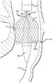
Referring now to the drawings, and initially to FIG. 1, there is shown the distal end of a transmission device 10 of the present invention. The delivery device generally includes a delivery catheter 20, and a pusher catheter 30 slidably contained within the delivery catheter 20. Preferably, the pusher catheter 30 is a multi-lumen catheter that includes a lumen for slidably containing and maintaining a line of three attachment cables 40 (hereinafter "valve-retaining cables") (see fig. 3), each having a releasable grasping mechanism 50 at its distal end. The delivery device 10 further includes at least one positioning mechanism 60 for assisting the tool or implant 1 in completing the navigation from the expanded, unfolded configuration to the folded, deployed configuration. In one embodiment, the at least one positioning mechanism 60 is attached to the distal end of the delivery catheter 20. In another embodiment, the at least one positioning mechanism 60 is slidably contained within the delivery catheter 20, similar to the valve-retaining cable 40.
The delivery catheter 20 is an outer sheath defining a single lumen for housing the pusher catheter 30, the tool or implant 1, the valve-retaining cable 40, and the positioning mechanism 60. When loaded, the delivery catheter 20 receives a tool or implant 1 near its distal end 22. Preferably, the implant 1 is an implant similar to those taught and described in U.S. patent publication No. 2006/0271166. The delivery catheter 20 may be formed with a preset bend at its distal end. A positive effect is achieved by using a preset bend of 180 degrees.
Fig. 2a and 2b show two similar embodiments of the pusher catheter 30 of the present invention defining seven lumens. The pusher catheter 30 includes a central guidewire lumen 32 and three lumens 34 containing a valve retention cable 40 or positioning mechanism described below. The remaining three lumens 36 accommodate the remaining valve retention cables or positioning mechanisms. To save space, the lumen 36 can be formed as an external depression, relying on the inner wall of the delivery catheter 20 to complete the lumen and contain the remaining valve-retaining cables or positioning mechanisms. In a preferred embodiment, lumen 34 contains valve-retaining cable 40, and lumen 36 contains positioning mechanism 60. In this embodiment, pusher catheter 30 may continue to be advanced even though positioning mechanism 60 can no longer be advanced.
In one embodiment, the positioning mechanism is small enough to install three valve retention mechanisms, and associated protective sheaths, in a single lumen 36, leaving the two other lumens 36 unused, or used as irrigation channels.
Fig. 3 shows the gripper mechanism 50 in an open configuration. The grasping mechanism 50 includes a hook 52 that slides within a mouth 54. The hook 52 defines a recess 56, the recess 56 being sized to receive a component (e.g., a commissure point or braid of a tool or implant 1). The mouth 54 defines a slot 58, the slot 58 also being sized to receive the assembly. Fig. 4 shows that when the grasping mechanism 50 is in the closed configuration, the groove 56 and the slot 58 together define a channel 59 that encloses the assembly therein.
Grasping mechanism 50 is attached to the distal end of valve retaining cable 40. The valve retaining cable 40 includes a wire 52 attached to a hook 52 and an elastic sheath 44 attached to a mouth 54. The wire 42 and hook 52 are slidably contained within the sheath 44 and the mouth 54. The sheath 44 is resilient so that it can be compressed in length. This feature prevents accidental release of a tool or component contained in the channel 59. For example, when a tool or implant is pulled back into the delivery sheath 20 during recovery, a load is placed on the lead 42 causing it to stretch. If the sheath 44 is not compressed, the wire 42 can be stretched enough to urge the hook 52 away from the mouth 54, thereby assuming the open configuration of FIG. 3. However, since the sheath 44 is compressed when the hook 52 is pulled back to the mouth 54 during closure, the sheath 44 elongates as the wire 42 is stretched, thereby maintaining the closed configuration of fig. 4.
The positioning mechanism 60 assists in inverting the tool or assembly 1. In one embodiment, as shown in fig. 1, 5 and 6, the positioning mechanism 60 connects the delivery catheter 20 to the implant 1 at a first point of inverted pre-folding (also referred to herein as "aortic flaring").
The positioning mechanism 60 may include a plurality of cords 62 and a linkage 64. The cord 62 may be any resilient wire-like material that is sufficiently flexible to transition from the navigation configuration to the deployed configuration. In the navigation configuration, as shown in fig. 1, the tether extends proximally from the distal end of the delivery catheter 20 to the connector 64. In the deployed configuration, as shown in fig. 5 and 6, the tether 62 extends distally from the distal end of the delivery catheter 20 to the connector 64. In one embodiment, the connector 64 can capture any individual braid or wire of the implant 1. In another embodiment, the connector 64 is designed to grab the intersection of two weaves or threads. In another embodiment, the connector 64 can grasp a separate attachment point (e.g., a coil, suture, etc.) that has been integrated into the mesh implant or tool 1. The length of the cord 62 is at least the length of the material of the implant 1, the material of the implant 1 extending distally of the connector 64 when the implant 1 is loaded into the delivery catheter 20. In this way, in the navigation configuration, the implant 1 is completely retained within the delivery catheter 20.
In another embodiment, the positioning mechanism 60 is similar in construction to the valve retaining cable 40 and releasable grasping mechanism 50. However, since the strength requirements of the positioning mechanism 60 are less than the strength requirements of the valve retaining cables 40 and their releasable grasping mechanisms 50, the positioning mechanism 60 may have a smaller diameter, allowing for an overall smaller delivery device 10. Rather than being attached to the distal end of the delivery catheter 20 as described above, the positioning mechanism 60 of this embodiment is slidably contained within the lumen 36 of the pusher catheter 30, as shown in FIG. 2.
Referring to fig. 5 and 6, the device 10 is designed to be able to pass over a guidewire 70 during navigation. A conical or other tapered dilator tip 80 is immediately adjacent the distal end 22 of the delivery catheter 20 and is flush with the distal end 22. Dilator 80 allows device 10 to be passed through the vasculature with minimal trauma. The dilator 80 is not physically attached to the delivery catheter 20 so that it is easily moved distally during delivery of the implant 1 to avoid interfering with the deployment of the implant 1.
Having described the various components of the present invention, it is now possible to set forth the various steps and configurations that are performed during navigation and deployment of the implant. Fig. 1 shows a navigation configuration of the device 10. In this navigation configuration, the implant 1 is loaded to the distal end of the delivery catheter 20 such that the implant 1 is in an elongated unfolded state. The pusher catheter 30 is disposed within the delivery catheter 20, the delivery catheter 20 having its distal end 22 proximal to the implant 1. Valve-retaining cable 40 extends distally from pusher catheter 30 and is connected to the commissure points of implant 1 using a releasable grasping mechanism 50. A conical dilator 80 is positioned proximate the distal end 22 of the delivery catheter 20. During navigation, the entire device 10 and implant 1 are passed over the guidewire 70 to the target location.
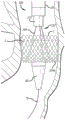
Fig. 5 shows an initial stage of deployment of the implant 1. The target location has been reached and the delivery catheter 20 is retracted while the pusher catheter 30 and valve retaining cable 40 remain stationary relative to the target location. Retracting the delivery catheter 20 causes the pusher catheter 30 to push the implant 1 out of the distal end 22 of the delivery catheter. As the implant 1 exits the delivery catheter 20, the implant 1 expands and the positioning mechanism 60 is advanced through the delivery catheter 20 until the tether 62 becomes taut or in the event that the positioning mechanism (positioning mechanism 60) slidably contained within the lumen of the pusher catheter 30 can no longer be advanced.
As seen in FIG. 6, further advancement of pusher catheter 30 causes the implant material at the proximal end of coupling member 64 to invert to the implant material at the distal end of coupling member 64. This is because the positioning mechanism 60 is tensioned and does not allow further distal advancement of the implant 1. As such, the inversion of the implant 1 is driven by the preformed folds in the implant, the memory metal comprising the implant 1, and the constraint provided by the positioning mechanism 60. It will be apparent that the transition from initial advancement to inversion of the implant occurs automatically and is affected by the length of the tether 64. As such, no operator experience is required for initiating the inversion. Nor is there any reliance on the anatomy to provide friction against the implant to initiate inversion.
Once the implant 1 has been fully deployed, the implant 1 functions fully prior to release. This allows to verify the proper operation of the implant 1 via one or more visualization modes before the complete release of the implant 1. If proper operation is not achieved, the grasping mechanism 50 can be used to pull the implant 1 back into the delivery catheter 20 so that the implant can be removed or re-deployed. If proper operation is verified, the connector 64 is actuated to release the braid or wire of the implant 1. The pusher catheter 30 and delivery catheter 20 are withdrawn slightly while maintaining connection with the implant 1 and device 10 via a releasable grasping mechanism. Subsequently, the grasping mechanism 50 is actuated to release the commissure points of the implant 1. The pusher catheter 30 is retracted into the delivery catheter 20 and guidewire 70 are withdrawn from the patient.
Fig. 7-21 illustrate another embodiment of a transfer device 100, the transfer device 100 being generally similar to the transfer device 10 previously described, particularly where like element numbers are used. However, the delivery device 100 includes a positioning cable assembly 110, the distal end of which 110 is best seen in fig. 7-10, having a sliding release mechanism for releasing the connection to the implant 1.
More specifically, positioning cord assembly 110 includes a plurality of cords 104, each cord of the plurality of cords 104 arranged in a generally closed loop. These looped cables 104 pass over a portion of the implant 1 and are thus able to maintain the implant 1 in a desired position during the procedure (e.g., are able to prevent distal movement of the implant 1). The cords can be detached from the implant 1 by releasing one end of each of the cords 104 to effectively open the loop shape. In this regard, withdrawal of the positioning cable assembly 110 also pulls the cable 104 out and away from the implant 1.
The release mechanism of the positioning cord assembly 110 is triggered by advancing the sliding member 114 from the retracted position seen in fig. 7 and 9 to the position seen in fig. 8 and 10. Note that tether 104 is connected to distal end 114B of sliding member 114 (e.g., fixed in place, or passed through member 114 back to the proximal end of positioning tether assembly 110), but is not shown in fig. 9 and 10 for purposes of example. Initially, free end 104B of cord 104 is positioned within recess 114A of sliding member 114 and captured by first slot 112A of outer cord sheath 112. When sliding member 114 is advanced, recess 114A is disposed below a wider second slot 112B, which second slot 112B allows free end 104B of cord 104 to be released.
As best seen in fig. 9, the free end 104B of the cord 104 generally has a larger size or diameter than the remainder of the cord 104 and can have a variety of different shapes, such as round, spherical, or even square. First slot 112A has a width large enough to accommodate the diameter of cord 104, but smaller than the diameter of free end 104B, thereby allowing cord 104 to slide laterally within slot 112A, rather than free end 104B passing therethrough.
The second slot 112B is disposed at a distal end of the first slot 112A and has a width greater than the free end 104B. In this regard, once recess 114A is aligned below the second slot 112B, as seen in fig. 10, free end 104B is released, thereby allowing cord 104 to assume a generally linear configuration, similar to cord 104 in fig. 8.
Although two slots are shown, in another embodiment, a single slot may alternatively be used. Specifically, the single slot may be similar in size to slot 112A, but extends to the distal end of the cord sheath 112. In this regard, the free end 104B is released when the recess 114A is advanced outside of the rope sheath 112.
The positioning cable assembly 110 may be constructed with an outer diameter that is generally small enough to be slidingly contained within one of the lumens 34 or 36 of the pusher catheter 30 shown in fig. 2a or 2 b.
Fig. 11-22 illustrate a proximal end or handle assembly 200 of the delivery device 100. The handle assembly generally includes a valve holding cable control group 210, a pusher catheter control 250, a drive mechanism 260, an irrigation end 280, and a tether control assembly 300.
The valve retention cable control group 210 includes a plurality of valve retention cable controls 212 received in recesses 214 in the handle 200, and a locking sheath 216. The individual valve retention cable controls 212 are best seen in fig. 12-14.
Fig. 12 shows an exploded view of the individual valve retention cable control 212. The control 212 includes a housing 218 to which the proximal end of the elastomeric sheath 44 that holds the cable 40 is attached (see FIG. 3). Slidingly contained within the housing 218 is a thumb slide 220, the thumb slide 220 being connected to the wire 42 of the retaining cable 40. Behind the thumb slide 220 is a spring-loaded catch 222. In operation, the thumb slide is pulled rearwardly toward the catch 222, pulling the wire 42 relative to the sheath 44, thereby retracting the hook 52 to the mouth 54 at the distal end of the cable 40. The catch 222 maintains the retaining cable 40 in the closed position. The hook 52 can be quickly released from the mouth 54 by depressing the catch 222.
Fig. 14 shows the thumb slide 220 in a forward, open position. The corresponding open position of the distal end of the cable 40 is also shown. Fig. 15 shows the thumb slide 220 in a closed position at the rear. The corresponding closed position of the distal end of the cable 40 is also shown. In addition, locking sheath 216 has been inserted through housing 218 and thumb slide 220 to prevent accidental release of implant 1 held in mouth 54 of retaining cable 40.
Referring back to fig. 11, there is shown three controls 212 arranged in the handle 200. It can also be seen that a single locking sheath 216 passes through the handle 200 and all three controls 212. The locking sheath 216 is a preventative feature to ensure that no control 212 is inadvertently opened. Once the valve position and operation has been verified, the physician can unlock all three controls 212 by removing a single sheath 216.
Fig. 15 is a partial view of the handle 200 of the device 100. Fig. 15 shows a pusher catheter control 250, which is shown as a sliding ring 250 that slides over the handle 200. The ring 250 is connected to the pusher catheter 30 through a slot 252 in the side of the handle 200. When the ring 250 is advanced to its most distal position, it can be rotated to lock the pusher catheter relative to the valve retaining cable 40.
The drive mechanism 260 is shown in fig. 16. The drive mechanism 260 includes a threaded rod 262 and a threaded nut assembly 264. Threaded nut assembly 264 includes a nut 266 contained within an annular handle 268 and a quick release 270. Rotation of environmental handle 268 causes nut 266 to act against screw 262. The annular grip 268 is axially fixed relative to the handle 200. The screw 262 is slidingly contained in the handle 200. As such, when nut 266 acts against screw 262, screw 262 advances or retracts within handle 200. The screw 262 is connected at its distal end to the transfer conduit 20. Thus, the rotatable threaded nut combination 264 allows for precise control of the relative motion between the pusher catheter 30 and the delivery catheter 20. Quick release 270 may be in the form of a button or handle that disengages nut 266 from the threads of screw 262 to allow pusher catheter 30 and valve-retaining cable 40 to be quickly retracted into delivery catheter 20.
It has been found that retracting the implant into the delivery catheter 20 is more easily successful when performed quickly. Slow retraction increases the risk that the catheter will catch. As such, the handle 200 has been designed to effect rapid retraction of the implant into the device 100 when desired. This is accomplished by ensuring that the ring 250 is rotated to a locked position so that when the handle is retracted relative to the delivery catheter, the pusher catheter 30 and the valve retaining cable 40 are fixed relative to each other, and thus simultaneously retracted. Depressing the quick release 270 while pulling the loop handle 268, while holding the delivery catheter 20 steady, causes the implant to be quickly pulled back into the delivery catheter 20.
The various components of the tether control assembly 300 are illustrated in fig. 17-21. The tether control assembly 300 generally includes a tether release controller 310 and a tether positioning mechanism 340.
The cord release control 310 is shown in fig. 17 and 18 and includes a housing 312 and a control loop handle 314. The housing 312 is secured to the proximal end of the outer cable jacket 112 of the positioning cable assembly 110 (see fig. 9 and 10). The control knob 314 is axially slidable relative to the housing 312 and is attached to the proximal end of the slide member 114 (fig. 9 and 10). Thus, with the control loop handle 314 in the forward position shown in fig. 18, the cord is released. When the control loop handle 314 is in the rearward position shown in fig. 17, the cable end is looped in the first slot 112A of the outer cable sheath 112. In the embodiment shown in the figures, the control loop handle 314 can be turned to a closed position, thereby locking it closed. Also included is a clip 320, which clip 320 can be used to prevent the control loop handle 314 from being pushed into the open position when the control loop handle 314 is accidentally actuated. The clip 320 is easily removed when it is desired to release the cord.
Fig. 19-21 illustrate a cord positioning mechanism 340. The cord positioning mechanism is a slide lock that includes a housing 342, a lever 344, and a grip block 346. The housing 342 passes through the outer cable sheath 112 and holds the cable sheath between the lever 344 and the grip block 346. When the lever 344 is lowered to the closed position, as shown in fig. 20, the outer cord sheath 112 and the cord contained therein are clamped between the lever 344 and the block 346 and cannot slide. Thus, the cord positioning mechanism 340 is fixed relative to the outer cord sheath 112. When the lever 344 is in the open position, the cord positioning mechanism 340 can slide over the outer cord sheath 112.
Fig. 22-29 show how the delivery device 100 according to the invention can be used for delivering an implant 1. First, the implant 1 is loaded into the delivery device 100. After rinsing the selected valve, each of the three valve retention cables 40 is independently attached to each of the three wireform eyelets on the implant. This can be accomplished by opening the valve holding cable control 212, pushing the thumb slide 220 forward to expose the hook 52 from the mouth 54. The hook 52 is placed through the linear eyelet and the thumb slide 220 is retracted rearwardly until it engages the catch 222. Doing so locks the slider 220 and closes the hook 52 in the mouth 54. It also compresses the outer elastic sheath 44 of the valve retaining cable 40 to maintain interference between the hook 52 and the mouth 54 even if a pushing force is applied to the cable 40 sufficient to stretch the cable, thereby preventing accidental release during the recovery process.
After all three valve retention cables 40 are attached, the positioning cord 104 is attached to the implant 1. (alternatively, the positioning cord 104 may be attached before the valve retaining cable 40). This may be accomplished by passing each of the three cords 104 through the center of the implant and through the ventricular return of the support structure of the implant at 120 ° intervals from the inside to the outside of the implant. Once all three tethers 104 have been threaded, the three tethers 104 pass back up through the valve, and the three tethers 104 are locked within the slots 112A of the outer tether sheath 112. Locking is accomplished by pulling on the control loop handle 314 and rotating it to the locked position shown in fig. 17.
Next, the pusher catheter 30 is pushed forward to capture the valve retaining cable 40. At the most distal position of the pusher catheter control ring 250, the ring 250 is rotated to lock the position of the pusher catheter 30 relative to the valve retaining cable 40.
The implant 1 is now ready to be loaded into the delivery catheter 20. The delivery catheter 20 is advanced by rotating the drive ring handle 268 towards the user and the implant 1 is slowly pulled back to the distal end of the delivery catheter 20. The position of the implant is significant despite the implant 1 having been loaded, thus enabling observation as to when the implant has reached that implant will be exposed from the delivery catheter 20 sufficiently to be able to reverse its orientation. At this point, the cable positioning mechanism 340 in the unlocked position is slid down the sheath 112 until it contacts the delivery catheter spool body 282 (fig. 11), and the lever 344 is moved to the locked position.
Continued loading of the implant into the delivery catheter 20 causes the cable 104 and cable sheath 112 to retract and the cable positioning mechanism 340 to move proximally relative to the delivery catheter spool 282. The implant is fully loaded when the dilator tip 80 has been partially retracted into the delivery catheter 20 and there is a smooth transition between the dilator tip and the delivery catheter tip.
As can be seen in fig. 22, the guidewire 70 is placed through the native aortic valve of the patient and extends outwardly through the vascular introducer at the location of the femoral access (access). The proximal end of the guidewire is inserted into the dilator tip 80 of the loaded delivery system and the system is advanced over the guidewire until the guidewire is visible through the proximal end of the delivery system. Thereafter, the proximal end of the guidewire remains stationary to maintain the position of the guidewire in the left ventricle of the patient, and the delivery system is advanced through the introducer into the vasculature and through the native aortic valve 4 (best seen in fig. 23). The guidewire passes through the lumen 32 of the pusher catheter 30.
Turning to fig. 24, the delivery catheter 20 is retracted proximally to expose a portion of the implant 1 and the tether 104. This is accomplished by rotationally driving the ring handle 268. When the implant 1 begins to be exposed, it expands itself outwardly against the native valve 4. During deployment, the operator maintains the implant position in the native valve of the patient. However, if the implant is pulled too high or pushed too low relative to the native valve, the implant can be retrieved by reversing the direction of rotation of the drive ring handle 268, which pulls the implant back into the sheath 20 for repositioning.
As shown in fig. 25, the implant 1 is then folded or inverted on itself by manipulating the implant with the tether 104 and pushing the proximal portion of the implant in a distal direction with the pusher catheter 110. More specifically, when the first layer of the implant has been deployed, the cable positioning mechanism 340 will have reached the delivery catheter spool body. This freezes the position of the ventricular circuit (distal end) of the implant so that further advancement of the implant will cause the implant to shorten and expand in preparation for valve inversion.
The open aspect of valve deployment has been described as the anchoring phase, since the implant has been expanded to contact native valve tissue, and the aortic flare of the device provides substantial resistance to migration. Once the anchoring phase has been initiated, the delivery catheter 20 is advanced through the access site and through the patient's vasculature. This aligns the dilator tip of the delivery catheter, which is coaxial with the native valve, with the curve of the delivery catheter 20 filling the outer curve of the native aortic arch.
After the catheter 20 has been advanced, the valve is continued to be deployed using the actuating loop handle for creating implant inversion. The act of inverting the implant also deploys the tissue valve components of the implant. Once the implant has been inverted, the valve begins to operate, but the operation is somewhat limited, depending on the proximity of the tether to the valve control cable.
After the inversion has been completed, the user releases the cord. First, the cable positioning mechanism 340 is released by releasing the lever 344, disengaging it from the gripping block 346. The cord positioning mechanism 340 is free to float along the outer cord sheath 112. The drive ring handle 268 is rotated to further withdraw the delivery catheter 20 from the implant. Once the delivery catheter 20 is fully retracted, the cable 104 can be removed by rotating and releasing the tension of the control loop handle 314 of the cable release control 310. Pulling the cord release control 310 gently will separate the cord 104 from the implant.
Once the tether 104 has been removed, only the valve retaining cable 40 remains connected to the implant 1, as shown in fig. 28. As previously discussed, these cables 40 are attached to the proximal features of the implant (e.g., the commissure points) and allow the physician to fully retract the implant 1 into the delivery device 100 if a problem arises during the delivery process. Specifically, to observe the entire valve movement without releasing the implant, the physician begins to retract pusher catheter 30 by rotating ring 250 away from the operator and sliding ring 250 in a proximal direction. As the pusher catheter 30 is retracted, the prosthetic valve begins to fully operate. The remaining attachment of the delivery system to the implant via the valve retaining cable 40 has less impact on the function of the implant.
Once satisfied, the physician next releases the implant by pulling on the locking sheath 216 at the proximal end of the handle assembly 200. With the locking sheath 216 removed, each of the three valve retaining cable controllers 212 can then be released. This is done by depressing the catch 222 and sliding the thumb slide 220 forward, releasing the implant 1. Each cable can be independently retracted into the transmission conduit after it has been detached. When all three cables are released, the valve is fully implanted and the delivery system can be removed from the patient's vascular introducer.
Finally, the delivery device 100 and the guidewire 70 are removed from the patient, leaving only the valve implant 1 in operation, as shown in fig. 29.
Although the present invention has been described in terms of particular embodiments and applications, those of ordinary skill in the art, in light of this teaching, will be able to generate additional embodiments and modifications without departing from the spirit of, or exceeding the scope of, the claimed invention. Accordingly, it is to be understood that the drawings and descriptions are provided herein by way of illustration only to facilitate understanding of the invention and should not be taken as limiting the scope of the invention.
Claims (7)
1. A delivery device for an invertible implant, the delivery device comprising:
a handle;
a catheter extending from a distal end of the handle, the catheter comprising a delivery catheter and a pusher catheter slidably disposed within the delivery catheter, wherein the delivery catheter is fixed relative to the distal end of the handle and the pusher catheter has a plurality of lumens;
a pusher catheter control movably attached to the handle and operably connected to the pusher catheter, the pusher catheter control axially moving relative to the handle such that the pusher catheter axially moves within the delivery catheter, wherein the pusher catheter control is a ring that slides over the handle and operably connects to the pusher catheter through a slot in the handle.
2. The delivery device of claim 1, wherein the sliding ring and the handle are configured such that the ring can be rotated to lock the pusher catheter relative to the handle when the ring is advanced to a distal position.
3. The delivery device of claim 2, wherein the loop surrounds the handle.
4. The delivery device of claim 1, wherein the pusher catheter comprises a longitudinal recess.
5. The delivery device of claim 1, wherein the pusher catheter comprises an outer surface defining three longitudinal recesses, each longitudinal recess sized to receive a valve-retaining cable or positioning mechanism between the inner surface of the delivery catheter and the outer surface of the pusher catheter.
6. A delivery device for an invertible implant, comprising:
a pusher catheter comprising a plurality of lumens;
three longitudinal grooves on the outer surface of the pusher catheter, each groove forming a channel for a valve-retaining cable or positioning mechanism when the pusher catheter is placed within a delivery catheter;
a handle having a controlling distal end of the proximal end of the pusher catheter, a control member disposed on an outer surface of the handle, the control member being connected to the pusher catheter and operable to advance or retract the pusher catheter within an outer catheter.
7. The delivery device of claim 6, wherein the plurality of lumens comprises at least three lumens.
Applications Claiming Priority (3)
| Application Number | Priority Date | Filing Date | Title |
|---|---|---|---|
| US201213473475A | 2012-05-16 | 2012-05-16 | |
| US13/473,475 | 2012-05-16 | ||
| CN201280074609.2A CN104684504B (en) | 2012-05-16 | 2012-10-22 | For the reversing transmission equipment and method of prosthese |
Related Parent Applications (1)
| Application Number | Title | Priority Date | Filing Date |
|---|---|---|---|
| CN201280074609.2A Division CN104684504B (en) | 2012-05-16 | 2012-10-22 | For the reversing transmission equipment and method of prosthese |
Publications (2)
| Publication Number | Publication Date |
|---|---|
| CN107233145A CN107233145A (en) | 2017-10-10 |
| CN107233145B true CN107233145B (en) | 2020-01-07 |
Family
ID=49584420
Family Applications (2)
| Application Number | Title | Priority Date | Filing Date |
|---|---|---|---|
| CN201280074609.2A Active CN104684504B (en) | 2012-05-16 | 2012-10-22 | For the reversing transmission equipment and method of prosthese |
| CN201710501145.3A Active CN107233145B (en) | 2012-05-16 | 2012-10-22 | Inverted delivery apparatus and method for prosthesis |
Family Applications Before (1)
| Application Number | Title | Priority Date | Filing Date |
|---|---|---|---|
| CN201280074609.2A Active CN104684504B (en) | 2012-05-16 | 2012-10-22 | For the reversing transmission equipment and method of prosthese |
Country Status (6)
| Country | Link |
|---|---|
| EP (1) | EP2849677A4 (en) |
| JP (3) | JP6118894B2 (en) |
| CN (2) | CN104684504B (en) |
| AU (2) | AU2012380319B2 (en) |
| CA (1) | CA2873589C (en) |
| WO (1) | WO2013172864A2 (en) |
Families Citing this family (3)
| Publication number | Priority date | Publication date | Assignee | Title |
|---|---|---|---|---|
| US10595874B2 (en) | 2017-09-21 | 2020-03-24 | W. L. Gore & Associates, Inc. | Multiple inflation endovascular medical device |
| US10786258B2 (en) | 2017-09-21 | 2020-09-29 | W. L. Gore & Associates, Inc. | Multiple inflation endovascular medical device |
| CN111643228B (en) * | 2020-08-04 | 2020-12-11 | 上海申淇医疗科技有限公司 | Conveying system for mitral valve repair |
Citations (2)
| Publication number | Priority date | Publication date | Assignee | Title |
|---|---|---|---|---|
| CN1870950A (en) * | 2003-10-23 | 2006-11-29 | 阿普特斯内系统公司 | Systems and methods for prosthesis delivery |
| WO2008072838A1 (en) * | 2006-12-11 | 2008-06-19 | S & G Biotech, Inc | Inserting device of artificial blood stent |
Family Cites Families (24)
| Publication number | Priority date | Publication date | Assignee | Title |
|---|---|---|---|---|
| CA935059A (en) * | 1970-02-27 | 1973-10-09 | Jewett-Ashley Holding Corp. | Catheter device |
| DK124690D0 (en) | 1990-05-18 | 1990-05-18 | Henning Rud Andersen | FAT PROTECTION FOR IMPLEMENTATION IN THE BODY FOR REPLACEMENT OF NATURAL FLEET AND CATS FOR USE IN IMPLEMENTING A SUCH FAT PROTECTION |
| US5325746A (en) * | 1991-09-27 | 1994-07-05 | Cook Incorporated | Wire guide control handle |
| US5261916A (en) * | 1991-12-12 | 1993-11-16 | Target Therapeutics | Detachable pusher-vasoocclusive coil assembly with interlocking ball and keyway coupling |
| AU677808B2 (en) * | 1992-12-01 | 1997-05-08 | Intella Interventional Systems, Inc. | Vibratory element for crossing stenoses |
| US6099558A (en) * | 1995-10-10 | 2000-08-08 | Edwards Lifesciences Corp. | Intraluminal grafting of a bifuricated artery |
| US6190360B1 (en) * | 1999-04-09 | 2001-02-20 | Endotex Interventional System | Stent delivery handle |
| US6783510B1 (en) * | 1999-07-08 | 2004-08-31 | C.R. Bard, Inc. | Steerable catheter |
| US6695813B1 (en) * | 1999-12-30 | 2004-02-24 | Advanced Cardiovascular Systems, Inc. | Embolic protection devices |
| US7374571B2 (en) * | 2001-03-23 | 2008-05-20 | Edwards Lifesciences Corporation | Rolled minimally-invasive heart valves and methods of manufacture |
| CA2533353A1 (en) * | 2003-07-21 | 2005-02-03 | The Trustees Of The University Of Pennsylvania | Percutaneous heart valve |
| EP1915105B1 (en) | 2005-05-27 | 2016-08-03 | HLT, Inc. | Stentless support structure |
| US20080082165A1 (en) * | 2006-09-28 | 2008-04-03 | Heart Leaflet Technologies, Inc. | Delivery Tool For Percutaneous Delivery Of A Prosthesis |
| JP5685352B2 (en) * | 2007-02-21 | 2015-03-18 | カオ グループ、インク. | Modular surgical laser system |
| US20080208328A1 (en) * | 2007-02-23 | 2008-08-28 | Endovalve, Inc. | Systems and Methods For Placement of Valve Prosthesis System |
| WO2008154450A1 (en) * | 2007-06-08 | 2008-12-18 | Valentx, Inc. | Methods and devices for intragastric support of functional or prosthetic gastrointestinal devices |
| FR2917601B1 (en) * | 2007-06-25 | 2010-03-19 | Stentys S A S | DEVICE FOR CONTROLLING A CATHETER |
| US8343029B2 (en) * | 2007-10-24 | 2013-01-01 | Circulite, Inc. | Transseptal cannula, tip, delivery system, and method |
| US9393115B2 (en) * | 2008-01-24 | 2016-07-19 | Medtronic, Inc. | Delivery systems and methods of implantation for prosthetic heart valves |
| US8721714B2 (en) | 2008-09-17 | 2014-05-13 | Medtronic Corevalve Llc | Delivery system for deployment of medical devices |
| CN102316923A (en) * | 2008-10-10 | 2012-01-11 | 奈科斯恩麦德系统有限公司 | Practice thrift stock's conduit system |
| AU2010286587B2 (en) * | 2009-08-27 | 2013-10-17 | Medtronic Inc. | Transcatheter valve delivery systems and methods |
| US8998980B2 (en) * | 2010-04-09 | 2015-04-07 | Medtronic, Inc. | Transcatheter prosthetic heart valve delivery system with recapturing feature and method |
| CN103124537B (en) * | 2010-05-10 | 2015-08-26 | 心叶科技公司 | Without rack supporting structure |
-
2012
- 2012-10-22 CN CN201280074609.2A patent/CN104684504B/en active Active
- 2012-10-22 WO PCT/US2012/061393 patent/WO2013172864A2/en active Application Filing
- 2012-10-22 EP EP12876788.6A patent/EP2849677A4/en not_active Withdrawn
- 2012-10-22 AU AU2012380319A patent/AU2012380319B2/en not_active Ceased
- 2012-10-22 CA CA2873589A patent/CA2873589C/en active Active
- 2012-10-22 JP JP2015512616A patent/JP6118894B2/en active Active
- 2012-10-22 CN CN201710501145.3A patent/CN107233145B/en active Active
-
2017
- 2017-03-27 JP JP2017061152A patent/JP6205514B2/en active Active
- 2017-09-04 JP JP2017169823A patent/JP6473905B2/en active Active
-
2018
- 2018-01-18 AU AU2018200425A patent/AU2018200425B2/en not_active Ceased
Patent Citations (2)
| Publication number | Priority date | Publication date | Assignee | Title |
|---|---|---|---|---|
| CN1870950A (en) * | 2003-10-23 | 2006-11-29 | 阿普特斯内系统公司 | Systems and methods for prosthesis delivery |
| WO2008072838A1 (en) * | 2006-12-11 | 2008-06-19 | S & G Biotech, Inc | Inserting device of artificial blood stent |
Also Published As
| Publication number | Publication date |
|---|---|
| EP2849677A2 (en) | 2015-03-25 |
| JP2017148525A (en) | 2017-08-31 |
| CN104684504B (en) | 2017-06-23 |
| AU2018200425B2 (en) | 2018-11-08 |
| WO2013172864A3 (en) | 2015-01-29 |
| JP6473905B2 (en) | 2019-02-27 |
| WO2013172864A2 (en) | 2013-11-21 |
| JP2018020133A (en) | 2018-02-08 |
| AU2012380319A1 (en) | 2015-01-22 |
| AU2018200425A1 (en) | 2018-02-08 |
| CA2873589C (en) | 2021-01-19 |
| JP6205514B2 (en) | 2017-09-27 |
| JP2015519944A (en) | 2015-07-16 |
| CN107233145A (en) | 2017-10-10 |
| AU2012380319B2 (en) | 2017-10-19 |
| EP2849677A4 (en) | 2015-07-15 |
| CA2873589A1 (en) | 2013-11-21 |
| CN104684504A (en) | 2015-06-03 |
| JP6118894B2 (en) | 2017-04-19 |
Similar Documents
| Publication | Publication Date | Title |
|---|---|---|
| US11413143B2 (en) | Inversion delivery device and method for a prosthesis | |
| US10820995B2 (en) | Inversion delivery device and method for a prosthesis | |
| JP5925300B2 (en) | Reverse delivery device and method for prosthesis | |
| AU2018200425B2 (en) | Inversion delivery device and method for a prosthesis | |
| US20220346952A1 (en) | Inversion delivery device and method for a prosthesis |
Legal Events
| Date | Code | Title | Description |
|---|---|---|---|
| PB01 | Publication | ||
| PB01 | Publication | ||
| SE01 | Entry into force of request for substantive examination | ||
| SE01 | Entry into force of request for substantive examination | ||
| GR01 | Patent grant | ||
| GR01 | Patent grant | ||
| TR01 | Transfer of patent right | ||
| TR01 | Transfer of patent right |
Effective date of registration: 20230506 Address after: California, USA Patentee after: EDWARDS LIFESCIENCES Corp. Address before: Minn Patentee before: HLT, Inc. |