JP5770182B2 - Oral care device - Google Patents
Oral care device Download PDFInfo
- Publication number
- JP5770182B2 JP5770182B2 JP2012523028A JP2012523028A JP5770182B2 JP 5770182 B2 JP5770182 B2 JP 5770182B2 JP 2012523028 A JP2012523028 A JP 2012523028A JP 2012523028 A JP2012523028 A JP 2012523028A JP 5770182 B2 JP5770182 B2 JP 5770182B2
- Authority
- JP
- Japan
- Prior art keywords
- liquid
- port
- reservoir
- cleaning
- providing
- Prior art date
- Legal status (The legal status is an assumption and is not a legal conclusion. Google has not performed a legal analysis and makes no representation as to the accuracy of the status listed.)
- Active
Links
Images


Classifications
-
- A—HUMAN NECESSITIES
- A61—MEDICAL OR VETERINARY SCIENCE; HYGIENE
- A61C—DENTISTRY; APPARATUS OR METHODS FOR ORAL OR DENTAL HYGIENE
- A61C17/00—Devices for cleaning, polishing, rinsing or drying teeth, teeth cavities or prostheses; Saliva removers; Dental appliances for receiving spittle
- A61C17/02—Rinsing or air-blowing devices, e.g. using fluid jets or comprising liquid medication
- A61C17/0211—Rinsing or air-blowing devices, e.g. using fluid jets or comprising liquid medication specially adapted for rinsing the teeth of at least one jaw simultaneously
-
- A—HUMAN NECESSITIES
- A61—MEDICAL OR VETERINARY SCIENCE; HYGIENE
- A61C—DENTISTRY; APPARATUS OR METHODS FOR ORAL OR DENTAL HYGIENE
- A61C17/00—Devices for cleaning, polishing, rinsing or drying teeth, teeth cavities or prostheses; Saliva removers; Dental appliances for receiving spittle
- A61C17/02—Rinsing or air-blowing devices, e.g. using fluid jets or comprising liquid medication
- A61C17/0202—Hand-pieces
-
- A—HUMAN NECESSITIES
- A61—MEDICAL OR VETERINARY SCIENCE; HYGIENE
- A61C—DENTISTRY; APPARATUS OR METHODS FOR ORAL OR DENTAL HYGIENE
- A61C17/00—Devices for cleaning, polishing, rinsing or drying teeth, teeth cavities or prostheses; Saliva removers; Dental appliances for receiving spittle
- A61C17/02—Rinsing or air-blowing devices, e.g. using fluid jets or comprising liquid medication
- A61C17/0217—Rinsing or air-blowing devices, e.g. using fluid jets or comprising liquid medication having means for manually controlling the supply of two or more fluids, e.g. water and air
-
- A—HUMAN NECESSITIES
- A61—MEDICAL OR VETERINARY SCIENCE; HYGIENE
- A61C—DENTISTRY; APPARATUS OR METHODS FOR ORAL OR DENTAL HYGIENE
- A61C17/00—Devices for cleaning, polishing, rinsing or drying teeth, teeth cavities or prostheses; Saliva removers; Dental appliances for receiving spittle
- A61C17/02—Rinsing or air-blowing devices, e.g. using fluid jets or comprising liquid medication
- A61C17/024—Rinsing or air-blowing devices, e.g. using fluid jets or comprising liquid medication with constant liquid flow
-
- A—HUMAN NECESSITIES
- A61—MEDICAL OR VETERINARY SCIENCE; HYGIENE
- A61C—DENTISTRY; APPARATUS OR METHODS FOR ORAL OR DENTAL HYGIENE
- A61C17/00—Devices for cleaning, polishing, rinsing or drying teeth, teeth cavities or prostheses; Saliva removers; Dental appliances for receiving spittle
- A61C17/02—Rinsing or air-blowing devices, e.g. using fluid jets or comprising liquid medication
- A61C17/028—Rinsing or air-blowing devices, e.g. using fluid jets or comprising liquid medication with intermittent liquid flow
-
- A—HUMAN NECESSITIES
- A61—MEDICAL OR VETERINARY SCIENCE; HYGIENE
- A61C—DENTISTRY; APPARATUS OR METHODS FOR ORAL OR DENTAL HYGIENE
- A61C19/00—Dental auxiliary appliances
- A61C19/06—Implements for therapeutic treatment
- A61C19/063—Medicament applicators for teeth or gums, e.g. treatment with fluorides
- A61C19/066—Bleaching devices; Whitening agent applicators for teeth, e.g. trays or strips
-
- B—PERFORMING OPERATIONS; TRANSPORTING
- B33—ADDITIVE MANUFACTURING TECHNOLOGY
- B33Y—ADDITIVE MANUFACTURING, i.e. MANUFACTURING OF THREE-DIMENSIONAL [3D] OBJECTS BY ADDITIVE DEPOSITION, ADDITIVE AGGLOMERATION OR ADDITIVE LAYERING, e.g. BY 3D PRINTING, STEREOLITHOGRAPHY OR SELECTIVE LASER SINTERING
- B33Y80/00—Products made by additive manufacturing
Landscapes
- Health & Medical Sciences (AREA)
- Dentistry (AREA)
- Epidemiology (AREA)
- Life Sciences & Earth Sciences (AREA)
- Animal Behavior & Ethology (AREA)
- General Health & Medical Sciences (AREA)
- Public Health (AREA)
- Veterinary Medicine (AREA)
- Oral & Maxillofacial Surgery (AREA)
- Cosmetics (AREA)
- Dental Tools And Instruments Or Auxiliary Dental Instruments (AREA)
- Brushes (AREA)
- Medical Preparation Storing Or Oral Administration Devices (AREA)
- Medicines Containing Material From Animals Or Micro-Organisms (AREA)
- Seal Device For Vehicle (AREA)
- Apparatus For Radiation Diagnosis (AREA)
Description
本開示は、哺乳類の口腔に有益効果を提供する、家庭用用途に好適な口腔ケア装置に関連する。 The present disclosure relates to an oral care device suitable for home use that provides a beneficial effect to the oral cavity of a mammal.
定期的な専門家による歯科検診に加え、日常的な口腔衛生が一般的に、歯周病、歯肉炎及び/又は虫歯の発現、進行及び/又は悪化に対する効果的な予防措置として認識されている。しかし残念なことに、十分な歯磨きやデンタルフロスの実施を行っている最も注意深い個人でさえも、多くの場合、歯茎の奥及び/又は歯間深くの食物微粒子、歯垢又はバイオフィルムに届き、緩めかつ除去することができていない。殆どの個人は、歯石(tarter)堆積物を除去するために、半年ごとに専門家による歯の洗浄を受ける。 In addition to regular professional dental examinations, routine oral hygiene is generally recognized as an effective preventive measure against the onset, progression and / or worsening of periodontal disease, gingivitis and / or caries. . But unfortunately even the most attentive individuals who are doing sufficient brushing and flossing often reach food particulates, plaque or biofilm deep in the gums and / or between teeth, It cannot be loosened and removed. Most individuals undergo professional tooth cleaning every six months to remove tarter deposits.
長年にわたり、単純な歯の家庭洗浄を促進するために、製品が考案されてきたが、使用が簡単でかつ歯及び/又は歯肉若しくは歯肉縁下部の全ての表面を同時に洗浄するための単一の装置は未だ入手可能でない。従来的な歯ブラシは広範に使用されているがこれは、効果的であるためには多大な労力を投じることを必要とし、更に従来の歯ブラシは隣接歯間領域を十分に洗浄することができない。歯間領域の洗浄は現在、歯ブラシ以外に、フロス、楊枝又はいくつかのそのような他の追加的な装置を必要とする。 Over the years, products have been devised to facilitate simple home cleaning of teeth, but are simple to use and a single to clean teeth and / or all surfaces of the gingiva or subgingival margin simultaneously The device is not yet available. Conventional toothbrushes are widely used, but this requires a great deal of effort to be effective, and further, conventional toothbrushes cannot adequately clean adjacent interproximal areas. Interdental cleaning currently requires a floss, toothpick or some other such additional device in addition to the toothbrush.
電気歯ブラシは非常な人気を博しており、これらは歯ブラシを使用するために必要な労力の投入を低減するものの、これらは依然として適切な隣接歯間の洗浄を確実にするためには不十分である。口腔イリガートルは、歯の間の隣接歯間領域を洗浄するものとして既知である。しかしながら、このような装置は、細片を除去するために、関連する正確な歯間領域に向けられなくてはならない単一のジェットを有する。ウォーターポンプ式洗浄機はそのため、典型的には、大きな食物微粒子をそこに捉えるブレースを有する歯に関してのみ、有意義である。細片及び歯垢の両方が歯から除去されるべき場合においては、現在、多くの装置が組み合わせて使用されなくてはならず、これは非常に時間がかかり、不便であることが理解される。 Although electric toothbrushes have become very popular and they reduce the effort input required to use toothbrushes, they are still insufficient to ensure proper inter-tooth cleaning. is there. Oral irrigator is known as cleaning the interproximal region between teeth. However, such a device has a single jet that must be directed to the associated precise interproximal region to remove debris. A water pump washer is therefore typically only meaningful for teeth that have braces that trap large food particles therein. In the case where both debris and plaque are to be removed from the tooth, it is now understood that many devices must be used in combination, which is very time consuming and inconvenient. .
加えて、このような実施及び装置が効果的であるためには、消費者が技術及び/又は指示を高度に遵守することが要求される。時間、洗浄/処理方式、技術等のユーザー間における違いは、歯の洗浄に影響する。 In addition, for such implementations and devices to be effective, consumers are required to be highly compliant with technology and / or instructions. Differences between users, such as time, cleaning / treatment methods, technology, etc., affect tooth cleaning.
本発明は、既存の口腔衛生装置及び方法を用いて上記の不利点の1つ以上を改善するか、又は少なくとも既知の技術よりも有利な代替技術を市場にもたらし、かつまた有害な状態を改善するか、若しくは口腔の美的外観を改善するために使用され得る。 The present invention uses existing oral hygiene devices and methods to ameliorate one or more of the above disadvantages, or at least bring alternative technologies to the market that are more advantageous than known technologies, and also improve harmful conditions. Or can be used to improve the aesthetic appearance of the oral cavity.
本発明は、哺乳類の口腔に有益効果を提供するシステムで使用するために好適な口腔ケア装置を対象とする。装置は、液体が有益効果を提供するために有効な条件下で口腔の複数の表面と接触する際に口腔の有益効果を提供するために有効な液体の往復運動を提供するための手段を含む。 The present invention is directed to an oral care device suitable for use in a system that provides beneficial effects to the oral cavity of a mammal. The apparatus includes means for providing a reciprocating motion of the liquid effective to provide an oral beneficial effect when the liquid contacts multiple surfaces of the oral cavity under conditions effective to provide the beneficial effect. .
用語「液体の往復移動」及び「液体の往復」は、本明細書において互換的に使用される。本明細書において使用するとき、双方の用語とも、哺乳類の口腔表面にわたって、第1の流れ方向から第1の流れ方向と反対の第2の流れ方向へと、液体の流れ方向を前後に変更することを意味する。 The terms “liquid reciprocation” and “liquid reciprocation” are used interchangeably herein. As used herein, both terms change the flow direction of liquid back and forth from a first flow direction to a second flow direction opposite the first flow direction across the mammalian oral cavity surface. Means that.
「効果的なフィット又は封止」とは、口腔内の複数の表面上又はその周囲に液体を方向付けるための手段の間の封止のレベルが、使用される液体量を低減又は最小化し、ユーザーの快適性を維持する(例えば、窒息又は嘔吐を避ける)ように使用中にトレイから口腔内に漏れる液体の量が十分に低いものであることを意味する。制限を意図しないが、嘔吐とは、軟口蓋、咽頭壁、扁桃領域又は舌の付け根の刺激によって生じる咽喉の奥の反射的な(すなわち、意図的な運動ではない)筋肉収縮であり、異物が咽頭及び気管に侵入することを防ごうとする防御運動を意図するものとして理解される。嘔吐運動は個人によってばらつきがある(例えば、口のどの領域がこれを刺激するか)。嘔吐の身体的な原因に加え、嘔吐に対する心理的要素が存在し得る(例えば、窒息に対する恐怖がある人々は、口内に何かが入ると容易に嘔吐し得る)。 “Effective fit or seal” means that the level of seal between means for directing liquid on or around multiple surfaces in the oral cavity reduces or minimizes the amount of liquid used; It means that the amount of liquid that leaks from the tray into the oral cavity during use is low enough to maintain user comfort (eg, avoid suffocation or vomiting). Although not intended to be limiting, vomiting is a reflex (ie, not intentional movement) muscle contraction in the back of the throat caused by stimulation of the soft palate, pharyngeal wall, tonsil region, or base of the tongue, and the foreign body is the pharynx And is intended as a defensive movement intended to prevent entry into the trachea. Vomiting varies from individual to individual (eg, which area of the mouth stimulates this). In addition to the physical cause of vomiting, there may be a psychological component of vomiting (eg, people who are afraid of suffocation can easily vomit if something enters their mouth).
本明細書において使用するとき「液体を運搬する手段」とは、それによって、本発明によるシステム及び装置全体にわたって液体が移動又は移送され得る構造を含み、非限定的に経路、導管、管、ポート、ポータル、チャネル、ルーメン、パイプ及びマニホールドが挙げられる。液体を運搬するためのこのような手段は、液体の往復運動を提供する装置及び口腔表面上及びその周囲に液体を方向付ける手段に使用され得る。このような運搬手段はまた、液体を収容するためのリザーバから、方向付け手段に液体を提供し、かつ往復運動手段に液体を提供する(リザーバが往復運動手段を収納する手持ち式装置内に収容されていても又は基部ユニットに収容されていても)。運搬手段はまた、基部ユニットから手持ち式装置内に収容される液体リザーバに液体を提供する。例えば、ヒトなどの哺乳類の口腔に有益効果を提供するために有用な方法、装置及びシステムが本明細書において記載される。 As used herein, “means for transporting liquid” includes structures by which liquid can be moved or transferred throughout the system and apparatus according to the present invention, including but not limited to pathways, conduits, tubes, ports. Portals, channels, lumens, pipes and manifolds. Such means for transporting liquids can be used in devices that provide reciprocal movement of liquids and means for directing liquids on and around the oral surface. Such transport means also provides liquid from the reservoir for containing liquid to the directing means and liquid to the reciprocating means (the reservoir is contained in a hand-held device containing the reciprocating means). Or even in the base unit). The carrier means also provides liquid from the base unit to a liquid reservoir housed in the handheld device. For example, methods, devices and systems useful for providing beneficial effects to the oral cavity of a mammal such as a human are described herein.
方法は、口腔の複数の表面を、所望の有益効果を口腔に提供するために有効な液体と接触させることを含む。このような方法において、口腔の複数の表面にわたる液体の往復運動が、所望の有益効果を口腔に提供するために有効な条件下で提供される。複数の表面の液体との接触は、実質的に同時に行われ得る。実質的に同時とは、口腔の複数の表面全てが必ずしも流体と同時に接触するわけではないが、表面の大部分が同時に接触するか又は全ての表面が同時に接触する場合と同様の全体効果を短時間の間に提供することを意味する。 The method includes contacting a plurality of surfaces of the oral cavity with a liquid effective to provide a desired beneficial effect to the oral cavity. In such a method, liquid reciprocation across multiple surfaces of the oral cavity is provided under conditions effective to provide the desired beneficial effect to the oral cavity. Contact with multiple surface liquids can occur substantially simultaneously. Substantially simultaneous does not mean that all the surfaces of the oral cavity are in contact with the fluid at the same time, but the overall effect is similar to when most of the surfaces are in contact at the same time or all surfaces are in contact at the same time. Means offering during time.
口腔内に所望の有益効果を提供するための条件は、求められる特定の環境、状況及び効果によって変化し得る。異なる変数は、これらが液体の特定の速度を生じるという点において相互依存的である。速度要件は、いくつかの実施形態における配合の関数であり得る。例えば、速度、添加物(例えば、研磨剤、ずり減粘剤など)及び配合物の一般的な流量特性の変化により、同じレベルの有効性を生成するためのジェットの速度要件は変化し得る。求められる特定の有益効果を達成するための適切な条件を提供するために検討され得る要因としては、非限定的に、液体蒸気の速度及び/又は流量及び/又は圧力、液体の脈動、液体のスプレー形状又はスプレーパターン、液体の温度及び液体の往復運動周期の周波数が挙げられる。 Conditions for providing a desired beneficial effect in the oral cavity can vary depending on the particular environment, situation and effect desired. The different variables are interdependent in that they produce a specific velocity of the liquid. The speed requirement may be a function of the formulation in some embodiments. For example, changes in speed, additives (eg, abrasives, shear thinning agents, etc.) and the general flow characteristics of the formulation can change the jet speed requirements to produce the same level of effectiveness. Factors that may be considered to provide appropriate conditions to achieve the desired beneficial effect sought include, but are not limited to, liquid vapor velocity and / or flow rate and / or pressure, liquid pulsation, liquid Examples include the spray shape or spray pattern, the temperature of the liquid, and the frequency of the reciprocating period of the liquid.
液体圧力、すなわち、ジェットを通じて出る前のマニホールド圧力は、約0.5psi(3447.4Pa)〜約30psi(206.8kPa)又は約3〜約15psi(約20.7〜約103.4kPa)、又は約5psi(34.5kPa)であり得る。液体の流量は、約10mL/s〜約60mL/s、又は約20mL/s〜約40mL/sであり得るより大きくかつより高品質のジェットは、所与の圧力/速度においてより高い流量を必要とすることに留意すべきである。パルス周波数(パルス長さ及び供給量(mL/パルス))は約0.5Hz〜約50Hz、又は約5Hz〜約25Hzであり得る。供給パルスデューティー・サイクルは約10%〜100%、又は約40%〜約60%であり得る。100%においてはパルスが存在せず、代わりに液体の連続的な流れが存在することに留意すべきである。供給パルス容積(全てのジェット/ノズルを通じた合計容積)は約0.2mL〜約120mL又は約0.5mL〜約15mLであり得る。噴出されるパルスの速度は約4cm/s〜約400cm/s、又は約20cm/s〜約160インチ/sであり得る。真空デューティー・サイクルは約10%〜100%又は約50%〜100%であり得る。真空は常に100%であることに留意する。容量供給と真空比率は、約2:1〜約1:20又は約1:1〜1:10であり得る。 The liquid pressure, i.e. the manifold pressure before exiting through the jet, is about 0.5 psi (3447.4 Pa) to about 30 psi (206.8 kPa) or about 3 to about 15 psi (about 20.7 to about 103.4 kPa), or It can be about 5 psi (34.5 kPa). Larger and higher quality jets may require higher flow rates at a given pressure / velocity, which can be from about 10 mL / s to about 60 mL / s, or from about 20 mL / s to about 40 mL / s It should be noted that. The pulse frequency (pulse length and delivery rate (mL / pulse)) can be from about 0.5 Hz to about 50 Hz, or from about 5 Hz to about 25 Hz. The supply pulse duty cycle can be about 10% to 100%, or about 40% to about 60%. It should be noted that at 100% there is no pulse and instead there is a continuous flow of liquid. The feed pulse volume (total volume through all jets / nozzles) can be from about 0.2 mL to about 120 mL or from about 0.5 mL to about 15 mL. The speed of the ejected pulse can be from about 4 cm / s to about 400 cm / s, or from about 20 cm / s to about 160 inches / s. The vacuum duty cycle can be about 10% to 100% or about 50% to 100%. Note that the vacuum is always 100%. The volume supply and vacuum ratio can be about 2: 1 to about 1:20 or about 1: 1 to 1:10.
本開示の利益を一度有すると、当業者は、特定の状況及び求められる所望の利益によって、様々な要因が調節及び選択され得ることを認識する。 Once having the benefits of this disclosure, those skilled in the art will recognize that various factors may be adjusted and selected depending on the particular circumstances and desired benefits desired.
液体は、求められる有益効果を提供するために有効な少なくとも1つの成分又は薬剤を、口腔表面と接触したときに有益効果を提供するために有効な量で含む。例えば、液体としては、非限定的に洗浄剤、抗菌剤、鉱化剤、減感剤及び白化剤からなる群から選択される成分を含み得る。いくつかの実施形態において、2種類以上の液体が単一の期間に使用され得る。例えば、洗浄溶液が口腔に適用され得、その後、例えば白化剤又は抗菌剤を含有する第2溶液が続く。溶液はまた、単一の適用によって2種類以上の利益を達成するために複数の薬剤を含み得る。例えば、以下で更に記載されるように、溶液は洗浄剤及び有害な状態を改善するための薬剤の両方を含み得る。加えて、口腔に2つ以上の有益効果を提供するために、単一の溶液が有効であり得る。例えば、溶液は口腔を洗浄し、かつ抗菌剤として作用するか、又は口腔を洗浄し、かつ歯を白化する単一の薬剤を含み得る。 The liquid comprises at least one component or agent effective to provide the desired beneficial effect in an amount effective to provide the beneficial effect when in contact with the oral surface. For example, the liquid may include a component selected from the group consisting of, but not limited to, a detergent, an antibacterial agent, a mineralizer, a desensitizer, and a whitening agent. In some embodiments, more than one type of liquid can be used in a single period. For example, a cleaning solution may be applied to the oral cavity followed by a second solution containing, for example, a whitening agent or an antimicrobial agent. A solution may also contain multiple agents to achieve more than one benefit with a single application. For example, as described further below, the solution may include both a cleaning agent and an agent to ameliorate the harmful condition. In addition, a single solution may be effective to provide more than one beneficial effect to the oral cavity. For example, the solution may contain a single agent that cleans the oral cavity and acts as an antimicrobial agent, or cleans the oral cavity and whitens the teeth.
口腔の美的外観を改善するために有用な液体は、口腔内で歯を白化するために白化剤を含み得る。このような白化剤としては、非限定的に、過酸化水素及び過酸化カルバミド、又は歯に適用される際に過酸化水素水を生成し得る他の薬剤が挙げられる。このような薬剤は、リンス、歯磨き粉及び白化ストリップなどの口腔ケア白化製品に関連する分野において周知である。他の白化剤としては、シリカ、重炭酸ナトリウム、アルミナ、アパタイト及びバイオグラスなどの研磨剤を含み得る。 Liquids useful for improving the aesthetic appearance of the oral cavity may include a whitening agent to whiten teeth in the oral cavity. Such whitening agents include, but are not limited to, hydrogen peroxide and carbamide peroxide, or other agents that can generate aqueous hydrogen peroxide when applied to teeth. Such agents are well known in the field relating to oral care whitening products such as rinses, toothpastes and whitening strips. Other whitening agents may include abrasives such as silica, sodium bicarbonate, alumina, apatite and bioglass.
研磨剤は歯を洗浄及び/又は白化するように作用し得る一方で、いくつかの研磨剤はまた、エナメルの欠損及び歯の小管の露出により生じる歯の過敏症を改善するように作用し得る。例えば、バイオグラスなどのいくつかの物質の粒径(例えば、直径)は、露出した小管を遮蔽し、したがって歯の感度を低減するために有効であり得る。 While abrasives can act to clean and / or whiten teeth, some abrasives can also act to ameliorate dental sensitivities caused by enamel loss and exposure of tooth tubules . For example, the particle size (eg, diameter) of some materials, such as biograss, can be effective to shield exposed tubules and thus reduce tooth sensitivity.
いくつかの実施形態において、液体は、3〜6の炭素原子を有するアルコールを含有する抗菌組成物を含み得る。液体は抗菌口腔洗浄組成物、特に低減したエタノール含有量を有するか又は実質的にエタノールを含まず、歯垢、歯肉疾患及び口臭を防ぐために高い効果を提供するものであってよい。3〜6個の炭素原子を有するアルコールは脂肪族アルコールであることに留意する。3つの炭素を有する特定の脂肪族アルコールは、1−プロパノールである。 In some embodiments, the liquid can include an antimicrobial composition containing an alcohol having 3 to 6 carbon atoms. The liquid may be an antibacterial mouthwash composition, particularly one that has a reduced ethanol content or is substantially free of ethanol and provides high efficacy to prevent plaque, gingival disease and bad breath. Note that alcohols with 3-6 carbon atoms are aliphatic alcohols. A specific aliphatic alcohol having 3 carbons is 1-propanol.
一実施形態において、液体は、(a)抗菌有効量のチモール及び1つ以上の他の精油、(b)約0.01%〜約70.0% v/v、又は約0.1%〜約30% v/v、又は約0.1%〜約10% v/v又は約0.2%〜約8% v/vの、3〜6個の炭素原子を有するアルコール及び(c)ビヒクルを含む、抗菌組成物を含み得る。アルコールは1−プロパノールであり得る。液体ビヒクルは水性又は非水性であり得、特定の稠度を有する組成物を提供するために増粘剤又はゲル化剤を含み得る。水及び水/エタノール混合物は、好ましいビヒクルである。 In one embodiment, the liquid comprises (a) an antibacterial effective amount of thymol and one or more other essential oils, (b) about 0.01% to about 70.0% v / v, or about 0.1% to About 30% v / v, or about 0.1% to about 10% v / v or about 0.2% to about 8% v / v of an alcohol having 3-6 carbon atoms and (c) a vehicle An antimicrobial composition can be included. The alcohol can be 1-propanol. The liquid vehicle can be aqueous or non-aqueous and can include a thickening or gelling agent to provide a composition having a particular consistency. Water and water / ethanol mixtures are the preferred vehicles.
液体の別の実施形態は、(a)抗菌有効量の抗菌剤、(b)約0.01%〜約70% v/v、又は約0.1%〜約30% v/v、又は約0.2%〜約8% v/vのプロパノール及び(c)ビヒクルを含む、抗菌組成物である。本実施形態の抗菌組成物は、従来技術のエタノールシステムと比較して意外な優れた供給システムを呈する。利用され得る代表的な抗菌剤としては、非限定的に、精油、塩化セチルピリジニウム(CPC)、クロルヘキシジン、ヘキセチジン、キトサン、トリクロサン、臭化ドミフェン、フッ化第一スズ、可溶性ピロリン酸塩、酸化亜鉛が挙げられるがこれに限定されない酸化金属、ペパーミント油、セージ油、血根草、二カルシウム水和物、アロエ、ポリオール、プロテアーゼ、リパーゼ、アミラーゼ、及びクエン酸亜鉛などが挙げられるがこれに限定されない金属塩などが挙げられる。本実施形態の特に好ましい態様は、例えば、約30% v/v以下、又は約10% v/v以下、又は約3% v/vの1−プロパノールを有する口腔洗浄剤などの、抗菌口腔組成物を対象とする。 Another embodiment of the liquid is: (a) an antimicrobial effective amount of an antimicrobial agent, (b) about 0.01% to about 70% v / v, or about 0.1% to about 30% v / v, or about An antimicrobial composition comprising 0.2% to about 8% v / v propanol and (c) a vehicle. The antibacterial composition of this embodiment exhibits a surprisingly superior delivery system compared to prior art ethanol systems. Representative antibacterial agents that can be utilized include, but are not limited to, essential oils, cetylpyridinium chloride (CPC), chlorhexidine, hexetidine, chitosan, triclosan, domifene bromide, stannous fluoride, soluble pyrophosphate, zinc oxide Examples include, but are not limited to, metal oxides, peppermint oil, sage oil, blood root grass, dicalcium hydrate, aloe, polyol, protease, lipase, amylase, and zinc citrate. Examples thereof include metal salts. Particularly preferred aspects of this embodiment are antibacterial oral compositions such as, for example, an oral cleanser having about 30% v / v or less, or about 10% v / v or less, or about 3% v / v 1-propanol. For objects.
液体の更に別の実施形態は、(a)抗菌有効量のチモール及び1つ以上の他の精油、(b)約0.01〜約30.0% v/v、約0.1%〜約10% v/v、又は約0.2%〜約8% v/vの3〜6個の炭素原子を有するアルコール、(c)約25% v/v以下の量のエタノール、(d)少なくとも1種類の界面活性剤、並びに(e)水を含む、エタノールを低減した抗菌口腔洗浄組成物である。好ましくは、エタノール及び3〜6個の炭素原子を有するアルコールの合計濃度は、30% v/v以下、又は25% v/v以下、又は22% v/v以下である。 Yet another embodiment of the liquid is: (a) an antibacterial effective amount of thymol and one or more other essential oils, (b) about 0.01 to about 30.0% v / v, about 0.1% to about 10% v / v, or about 0.2% to about 8% v / v of an alcohol having 3-6 carbon atoms, (c) ethanol in an amount up to about 25% v / v, (d) at least It is an antibacterial mouthwash composition with reduced ethanol, which contains one type of surfactant and (e) water. Preferably, the total concentration of ethanol and alcohols having 3 to 6 carbon atoms is 30% v / v or less, or 25% v / v or less, or 22% v / v or less.
別の実施形態において液体は、(a)抗菌有効量のチモール及び1つ以上の他の精油、(b)約0.01〜約30.0% v/v、約0.1%〜約10% v/v、又は約0.2%〜約8% v/vの3〜6個の炭素原子を有するアルコール、(c)少なくとも1種類の界面活性剤、並びに(d)水を含む、エタノールを含まない抗菌口腔洗浄組成物である。 In another embodiment, the liquid comprises (a) an antibacterial effective amount of thymol and one or more other essential oils, (b) about 0.01 to about 30.0% v / v, about 0.1% to about 10 % V / v, or about 0.2% to about 8% v / v of an alcohol having 3-6 carbon atoms, (c) at least one surfactant, and (d) ethanol containing water An antibacterial mouthwash composition that does not contain.
3〜6個の炭素原子を有するアルコールは好ましくは、1−プロパノール、2−プロパノール、1−ブタノール、2−ブタノール、第三級ブタノール及び対応するジオールから選択される。1−プロパノール及び2−プロパノールが好ましく、1−プロパノールが最も好ましい。 Alcohols having 3 to 6 carbon atoms are preferably selected from 1-propanol, 2-propanol, 1-butanol, 2-butanol, tertiary butanol and the corresponding diol. 1-propanol and 2-propanol are preferred, and 1-propanol is most preferred.
例えば、歯垢の形成、食物微粒子、バイオフィルムなどの除去又は分解など、洗浄によって口腔の口内衛生を一般的に改善することに加えて、本発明は口腔内の有害な状態を改善し、口腔の美的外観を改善する(例えば、歯の白化)ために有用である。有害な状態としては、非限定的に、虫歯、歯肉炎、炎症、歯周病と関連する症状、口臭、歯の感度及び菌感染などが挙げられる。液体自体は様々な形態であり得るが、ただしこれらは本発明の装置及び方法の使用に好適な流動特性を有する。例えば、液体は、溶液、エマルション及び分散液からなる群から選択され得る。いくつかの実施形態において、液体は液相(例えば、水相)中に分散した微粒子(例えば、研磨剤)を含み得る。このような場合において、研磨剤は、口腔表面に適用されるために、水相中に実質的に均一に分散する。他の実施形態において、水中油型又は油中水型エマルションが使用され得る。このような場合、液体は場合によって、連続的な水相中に実質的に均一に分散した非連続的な油相、又は連続的な油相中に実質的に均一に分散した非連続的な水性相を含む。更に他の実施形態において、液体は、薬剤がキャリア中に溶解しているか又はキャリア自体が所望の有益効果を提供するための薬剤とみなされ得る(例えば、通常内部に他の薬剤が溶解しているアルコール又はアルコール/水混合物)溶液であり得る。 In addition to generally improving oral hygiene of the oral cavity by washing, such as plaque formation, removal of food particulates, biofilms, etc., for example, the present invention improves oral harmful conditions, It is useful for improving the aesthetic appearance of teeth (for example, whitening of teeth). Harmful conditions include, but are not limited to, caries, gingivitis, inflammation, symptoms associated with periodontal disease, halitosis, dental sensitivity and bacterial infection. The liquid itself may take a variety of forms, but these have flow characteristics suitable for use with the apparatus and method of the present invention. For example, the liquid may be selected from the group consisting of solutions, emulsions and dispersions. In some embodiments, the liquid can include fine particles (eg, an abrasive) dispersed in a liquid phase (eg, an aqueous phase). In such a case, the abrasive is substantially uniformly dispersed in the aqueous phase for application to the oral surface. In other embodiments, an oil-in-water or water-in-oil emulsion may be used. In such cases, the liquid is optionally a discontinuous oil phase that is substantially uniformly dispersed in the continuous aqueous phase, or a discontinuous oil that is substantially uniformly dispersed in the continuous oil phase. Contains an aqueous phase. In still other embodiments, the liquid can be considered as a drug in which the drug is dissolved in the carrier or the carrier itself provides the desired beneficial effect (eg, other drugs normally dissolved therein). Alcohol or alcohol / water mixtures) solutions.
家庭用の用途に好適であり、歯及び/又は歯肉領域の複数の表面上に液体を方向付けるように適合された歯科用洗浄装置などの口腔ケア装置、加えてこのような装置を利用する方法及びシステムが本明細書において開示される。いくつかの実施形態において、口腔の表面は、液体と実質的に同時に接触する。本明細書において使用するとき、歯肉領域への言及は、非限定的に歯肉縁下部ポケットへの言及を含む。口腔の洗浄及び/若しくは美的外観の一般的な改善並びに/又は歯及び/若しくは歯肉領域の有害な状態の改善を提供し、それによって歯及び/又は歯肉領域の口腔衛生を改善するために効果的な条件下において、往復運動により歯及び/又は歯肉領域の複数の表面上に実質的に同時に適切な液体が方向付けられる。例えば、1つのこのような装置は、歯の表及び裏表面並びに隣接歯間領域上で液体を前後に往復運動させることによって洗浄周期を生成する一方で使用する洗浄液の量を最小化することにより、適切な洗浄液を使用して歯及び/又は歯肉領域を洗浄しかつ歯垢除去する。 An oral care device, such as a dental cleaning device, suitable for home use and adapted to direct liquid onto a plurality of surfaces of the tooth and / or gingival area, and a method of utilizing such a device And systems are disclosed herein. In some embodiments, the surface of the oral cavity is in contact with the liquid substantially simultaneously. As used herein, reference to a gingival region includes, but is not limited to, a reference to a subgingival pocket. Effective for providing general improvement of oral cleansing and / or aesthetic appearance and / or improvement of harmful conditions of teeth and / or gingival areas, thereby improving oral hygiene of teeth and / or gingival areas Under such conditions, the reciprocating motion directs the appropriate liquid on the surfaces of the tooth and / or gingival area substantially simultaneously. For example, one such device creates a cleaning cycle by reciprocating fluid back and forth on the front and back surfaces of teeth and adjacent interproximal regions, while minimizing the amount of cleaning liquid used. Use a suitable cleaning solution to clean and remove plaque and / or gingival areas.
液体の往復運動を提供する本発明の装置は、液体の往復運動を制御する手段を含む。制御手段は、液体を口腔の複数の表面上に方向付けるための手段に及びここから液体を運搬するための手段を含む。本明細書において以下でより詳細に記載されるように、いくつかの実施形態において、液体の往復運動を提供するための手段は、液体を受容及び排出するための複数のポータル、液体がそれを通じて運搬される複数の経路又は導管、及び液体の往復運動を提供するために液体の流れ方向を変えるための手段を含む。制御手段は、論理回路及び/又は機械的に制御された回路によって制御され得る。 The apparatus of the present invention that provides reciprocation of liquid includes means for controlling the reciprocation of liquid. The control means includes means for directing liquid onto the plurality of surfaces of the oral cavity and means for transporting liquid therefrom. As described in more detail hereinbelow, in some embodiments, the means for providing reciprocation of the liquid comprises a plurality of portals for receiving and discharging liquid, through which the liquid passes. It includes a plurality of paths or conduits to be conveyed and means for changing the flow direction of the liquid to provide reciprocal movement of the liquid. The control means may be controlled by logic circuits and / or mechanically controlled circuits.
いくつかの実施形態において、往復運動を提供するための装置は、液体を収容するためのリザーバに装置取り付けるか又は接続するための手段を含み得る。リザーバは装置に取り外し可能に取り付けられ得る。この場合において、リザーバ及び装置は、一方を他方に取り付けるための手段を含み得る。プロセスの完了後、リザーバは廃棄されて別のリザーバと交換されてもよく、又は再充填されて再使用されてもよい。他の実施形態において往復運動する装置は装置と一体のリザーバを含む。本明細書において記載される、装置が基部ユニットに取り付けられ得る実施形態において、リザーバは、装置と一体であっても又は装置に取り外し可能に取り付けられていても、基部ユニットの一部を形成する供給リザーバから充填され得る。基部ユニットが使用される場合、装置及び基部ユニットは一方を他方に取り付けるための手段を含む。 In some embodiments, a device for providing reciprocating motion may include means for attaching or connecting the device to a reservoir for containing liquid. The reservoir can be removably attached to the device. In this case, the reservoir and device may include means for attaching one to the other. After completion of the process, the reservoir may be discarded and replaced with another reservoir, or may be refilled and reused. In other embodiments, the reciprocating device includes a reservoir integral with the device. In embodiments described herein where the device can be attached to the base unit, the reservoir forms part of the base unit, whether integral with the device or removably attached to the device. Can be filled from a supply reservoir. Where a base unit is used, the apparatus and base unit include means for attaching one to the other.
装置は、液体を往復運動させるための手段を駆動するための電源を含む。例えば電池(再充電可能又は使い捨て)などの電源が、装置内(例えば、装置のハンドル内)に収容され得る。基部ユニットが利用され得る場合、基部は装置に出力を提供するための手段を含み得る。他の実施形態において基部ユニットは、装置内に含まれる再充電可能な電池を再充電するための手段を含み得る。 The apparatus includes a power source for driving the means for reciprocating the liquid. A power source, such as a battery (rechargeable or disposable), can be housed within the device (eg, within the handle of the device). If a base unit can be utilized, the base can include means for providing output to the device. In other embodiments, the base unit may include means for recharging a rechargeable battery contained within the device.
液体の往復運動を提供するための装置は、装置を、口腔の複数の表面に液体を方向付けるための手段(例えば、適用トレー又はマウスピース)に取り付けるための手段を含む。いくつかの実施形態において方向付け手段は、口腔の複数の表面と液体との実質的に同時の接触を提供する。取り付け手段は、マウスピースの装置への取り外し可能な取り付けを提供し得る。いくつかの実施形態において、多数のユーザーが自らのマウスピースを、往復運動手段を含む単一の装置と共に使用し得る。他の実施形態において、取り付け手段はマウスピースに取り外し不可能な取り付けを提供してもよく、よってマウスピースは装置の一体部分である。上記の往復運動を提供するための装置は、他の装置構成要素も含むハウジング内に収容されてもよく、本明細書において以下に記載される、液体を方向付け手段に提供するために好適な手持ち式装置を提供する。 An apparatus for providing reciprocal movement of liquid includes means for attaching the apparatus to a means (eg, an application tray or mouthpiece) for directing liquid to a plurality of surfaces of the oral cavity. In some embodiments, the directing means provides substantially simultaneous contact between the plurality of oral cavity surfaces and the liquid. The attachment means may provide a removable attachment of the mouthpiece to the device. In some embodiments, multiple users may use their mouthpiece with a single device that includes reciprocating means. In other embodiments, the attachment means may provide a non-removable attachment to the mouthpiece, so that the mouthpiece is an integral part of the device. The device for providing reciprocation as described above may be housed in a housing that also includes other device components, and is suitable for providing liquid to the directing means as described herein below. Provide a handheld device.
液体を口腔の表面上に方向付けるための手段(例えば、適用トレー又はマウスピース)は、多数の構成要素を含む。方向付け手段は、液体を複数の表面に近接するように維持するためのチャンバ(すなわち、液体接触チャンバ(LCC))を含む。「近接する」とは、液体が表面と接触した状態に維持されることを意味する。LCCは、マウスピースの前方内側壁部及び後方内側壁部、並びにマウスピースの前方内側壁部と後方内側壁部との間に延び、これと一体の壁部又は膜、及びいくつかの実施形態においては後方歯肉封止膜によって境界される空間によって画定される。前方及び後方内側壁部と共に、その間に延びる壁部及び後方歯肉封止膜がLCC膜(LCCM)を形成する。液体との均一かつ最適な接触を提供するために、歯に適合するマウスピースの配置によって、LCCMの一般的形状は、「U」又は「n」の形状である。LCCMは、特定の方向付け手段によって、可撓性又は剛性であり得る。膜は、LCCMの基本膜として配置され得る。LCCMの前方及び後方内側膜はそれぞれ、複数の開口部又はスロットを含み、液体がこれらを通じて口腔の複数の表面と接触するように方向付けられる。 The means for directing liquid onto the oral surface (eg, application tray or mouthpiece) includes a number of components. The directing means includes a chamber (ie, a liquid contact chamber (LCC)) for maintaining the liquid in close proximity to the plurality of surfaces. “Adjacent” means that the liquid remains in contact with the surface. The LCC extends between the front inner wall portion and the rear inner wall portion of the mouthpiece, and between the front inner wall portion and the rear inner wall portion of the mouthpiece, and a wall or membrane integral therewith, and some embodiments. Is defined by a space bounded by the posterior gingival sealing film. Along with the front and rear inner wall portions, the wall portion and the rear gingival sealing film extending therebetween form an LCC film (LCCM). In order to provide uniform and optimal contact with the liquid, the general shape of the LCCM is a “U” or “n” shape, depending on the placement of the mouthpiece that fits the teeth. The LCCM can be flexible or rigid depending on the specific orientation means. The membrane can be placed as the base membrane of LCCM. The LCCM's anterior and posterior medial membranes each include a plurality of openings or slots through which the liquid is directed to contact a plurality of oral cavity surfaces.
快適性を提供し、ユーザーの嘔吐反射を最小化するために、大きさ、形状、厚さ、材料、歯/歯肉の周囲に生成される容積、ノズル設計及び配置(これはマニホールド及び歯肉縁部封止と共に口腔及び歯と関連する)と関連して、LCCM設計が最大有効性のために最適化され得る。上記の組み合わせが、歯及び歯肉領域と液体との有効な接触を提供する。 Size, shape, thickness, material, volume generated around the teeth / gingiva, nozzle design and placement to provide comfort and minimize user vomiting reflex (this is the manifold and gingival margin LCCM design can be optimized for maximum effectiveness in conjunction with the oral cavity and teeth as well as sealing. The above combination provides effective contact between the teeth and gingival area and the liquid.
LCCMは、既知の体積を有する、制御され、分離された環境(すなわち、LCC)を提供し、歯及び/歯肉領域を液体と接触させ、その後、消費された液体、並びに細片、歯垢などをLCCから、口腔全体を液体、細片等に曝露することなく除去する。これは、液体の摂取の可能性を低減する。LCCMはまた、例えば、十分な洗浄を提供するために著しい流量が必要とされる場合に、個別のノズルを引くことなく、液体の流量及び圧力の増加を可能にする。LCCMはまた、口腔全体ではなくLCCの内部の領域のみが液体と接触するために、必要とされる際の液体量及び流量の低減を可能にする。LCCMはまた、歯及び歯肉領域上、これらを通じた及びこれらの周囲の液体との接触の制御された供給量及び持続時間を可能にし、液体と接触する領域上の液体のより高い濃度を可能にし、それによって液体のより有効な制御及び供給を提供する。 LCCM provides a controlled, isolated environment (ie, LCC) with a known volume, bringing the teeth and / or gingiva area into contact with the liquid, then the consumed liquid, as well as debris, plaque, etc. From the LCC without exposing the entire oral cavity to liquids, debris, etc. This reduces the possibility of liquid ingestion. LCCM also allows for an increase in liquid flow rate and pressure without pulling a separate nozzle if, for example, significant flow rates are required to provide sufficient cleaning. LCCM also allows for a reduction in the volume and flow rate of liquid when needed, because only the region inside the LCC is in contact with the liquid rather than the entire oral cavity. LCCM also allows for controlled delivery and duration of contact with and through liquids on and around the tooth and gingival areas, allowing for higher concentrations of liquid on areas that are in contact with liquid. , Thereby providing more effective control and supply of liquid.
LCCMの壁部の厚さは、必要な物理的性能特性を提供する一方で含有材料を最小化し性能を最適化するため、0.2mm〜1.5mmの範囲であり得る。LCCMの内側壁部と歯との間の距離は、最大快適性を提供する一方でカスタマイズ及びLCC容積要件を最小化するため、約0.1mm〜約5mmであってもよく、より典型的には、約2.5mmの平均距離である。 The wall thickness of the LCCM can range from 0.2 mm to 1.5 mm to provide the required physical performance characteristics while optimizing performance while minimizing the contained material. The distance between the inner wall of the LCCM and the teeth may be from about 0.1 mm to about 5 mm, more typically to provide maximum comfort while minimizing customization and LCC volume requirements. Is an average distance of about 2.5 mm.
マウスピースの寸法及び形状は、好ましくは、上の歯及び下の歯の両方のための3つの基本的な自在寸法を利用するが、設計は、個別のユーザーに快適性及び機能性を保証するために必要に応じて、異なるレベルのカスタマイズを可能にする機構を提供する。装置は、これが口の中で正しい位置にあるときのみ動作することを可能にする、スイッチ機構を組み込んでもよい。マウスピースは、口腔の複数の表面と液体との実質的に同時の接触を提供するために、上方区分及び下方区分の両方を含み得る。別の実施形態において、上方区分及び下方区分は、ユーザーの上の歯又は下の歯及び歯肉上で使用され得る単一のブリッジを使用して洗浄され得る(最初に洗浄のために一部分に配置され、その後、洗浄のために他の部分に配置される)。 The size and shape of the mouthpiece preferably utilizes three basic universal dimensions for both the upper and lower teeth, but the design ensures comfort and functionality for individual users. It provides a mechanism that allows different levels of customization as needed. The device may incorporate a switch mechanism that allows it to operate only when it is in the correct position in the mouth. The mouthpiece may include both an upper section and a lower section to provide substantially simultaneous contact of multiple surfaces of the oral cavity with the liquid. In another embodiment, the upper and lower sections can be cleaned using a single bridge that can be used on the user's upper teeth or lower teeth and gums (first placed in part for cleaning). And then placed in other parts for cleaning).
マウスピースの内側壁部内に収容される、本明細書においてスロット、ジェット又はノズルとしても称される開口部(これを通じて液体が方向付けられる)の数及び位置は変動し、使用状況及び環境、特定のユーザー及び求められる有益効果に基づき決定される。開口部の断面形状は、円形、楕円形、台形又は口腔の表面と液体との効果的な接触を提供する他の任意の形状を提供する他の形状であり得る。開口部の位置及び数は、所望の利益効果を提供するために有効な様々なスプレーパターンの液体ジェットを方向付けるように設計され得る。開口部直径は、効果的な洗浄、並びに平均ジェット速度及び適用範囲を提供するために、約0.1〜約3mm、又は約0.2mm〜約0.8mm、又は約0.5mmであり得る。 The number and location of openings (also referred to herein as slots, jets or nozzles), which are also referred to herein as slots, jets or nozzles, accommodated within the inner wall of the mouthpiece will vary, depending on the usage and environment, specific It is determined based on the user and the desired beneficial effect. The cross-sectional shape of the opening can be circular, oval, trapezoidal, or any other shape that provides any other shape that provides effective contact between the oral surface and the liquid. The location and number of openings can be designed to direct the various spray patterns of liquid jets effective to provide the desired benefits. The aperture diameter can be about 0.1 to about 3 mm, or about 0.2 mm to about 0.8 mm, or about 0.5 mm to provide effective cleaning and average jet velocity and coverage. .
口腔と液体とが接触する際に、最適な開口部の配置及び方向/角度は、歯間、上部、側部、後部及び歯肉ポケット表面を含むがこれに限定されない領域の実質的に全ての歯表面を適用範囲とすることを可能にする。別の実施形態において、開口部は、速度、密度及びファンパターン(完全な円錐、扇型、部分的円錐、ジェット)を調節するために、又は配合の検討により、異なる洗浄、適用範囲及びスプレーパターンを提供するために、異なる寸法及び異なる形状であり得る。ノズルはまた、管状に設計されてもよく、及び/又はLCCMから延びて方向付けられたスプレーを提供してもよく、又はホーススプリンクラーシステムと同様に歯にわたって拡張した適用範囲を提供するためにスプリンクラー様の機構として機能してもよい。ノズルは好ましくは、LCCMの内側壁部と一体であり、任意の数のアセンブリ又は当該分野において既知の形成技術によって内側壁部内に組み込まれ得る(機械加工、射出成型などを通じて膜内にインサート成型される)。 In contact between the oral cavity and the liquid, the optimal placement and orientation / angle of the openings includes substantially all teeth in areas including, but not limited to, interdental, upper, lateral, posterior and gingival pocket surfaces. Allows the surface to be covered. In another embodiment, the openings may have different cleaning, coverage and spray patterns to adjust speed, density and fan pattern (full cone, fan, partial cone, jet) or by formulation considerations. To provide different dimensions and shapes. The nozzle may also be designed to be tubular and / or provide a directed spray extending from the LCCM, or sprinkler to provide extended coverage over the teeth as well as a hose sprinkler system It may function as a similar mechanism. The nozzle is preferably integral with the inner wall of the LCCM and can be incorporated into the inner wall by any number of assemblies or forming techniques known in the art (insert molded into the membrane through machining, injection molding, etc. )
LCCMは、エチレンビニルアセテート(EVA)、熱可塑性エラストマー(TPE)又はシリコーンなどのエラストマー材料であってもよく、内側壁部の移動を可能にし、最小限の機械的構造でより大きなジェット適用領域を提供し、最適な性能を達成するための体積流量要件を低減する一方で、歯と直接接触した際に歯を保護するためにより柔軟でより可撓性の材料を提供する。可撓性膜はまた、その歯に適合する能力のために、広範なユーザーにとって許容可能な嵌合具を提供し得る。あるいは、LCCMは、剛性又は半剛性の材料(例えば、限定されないが熱可塑性)で作製され得る。 The LCCM may be an elastomeric material such as ethylene vinyl acetate (EVA), thermoplastic elastomer (TPE) or silicone, which allows for movement of the inner wall and allows greater jet coverage with minimal mechanical structure. It provides a softer and more flexible material to protect the teeth when in direct contact with the teeth while providing and reducing the volumetric flow requirements to achieve optimal performance. The flexible membrane may also provide a fitting that is acceptable to a wide range of users due to its ability to fit into the teeth. Alternatively, the LCCM can be made of a rigid or semi-rigid material (eg, but not limited to thermoplastic).
別の実施形態において、LCCMはまた研磨要素、例えば、フィラメント、テクスチャ、磨き要素、添加物(シリカなど)、他の洗浄及び/又は処理要件、加えて限定されないが処理、洗浄及び配置のために歯とLCCMとの間の最小限の距離を保証するために使用され得る他の形状要素を含む。 In another embodiment, the LCCM may also be used for polishing elements such as filaments, textures, polishing elements, additives (such as silica), other cleaning and / or processing requirements, but not limited to processing, cleaning and placement. Includes other shape elements that can be used to ensure a minimum distance between the tooth and the LCCM.
LCCMは、限定されないが、機械加工、射出成型、吹込み成形、押出成形、圧縮成型及び/又は真空成型などの、様々な方法により形成され得る。これはまたマニホールドと共に形成されつつマニホールド回路をLCC内に組み込む及び/又はマニホールド上にオーバーモールドされて最小アセンブリで一体構成を提供し得る。 The LCCM can be formed by various methods including, but not limited to, machining, injection molding, blow molding, extrusion molding, compression molding, and / or vacuum molding. This can also be integrated with the manifold circuit while being formed with the manifold and / or overmolded onto the manifold to provide a unitary construction with minimal assembly.
一実施形態において、LCCMは別個に作製されて、その後、接着剤、エポキシ、シリコーン、ヒートシール、超音波溶接及び熱接着材を含む任意の数の組み立て及び封止技術を使用して、マニホールドに組み立てられてもよい。LCCMは、マニホールドと組み立てた際に、これがいずれの追加的構成要素も用いずに好ましいデュアルマニホールド設計を効果的かつ効率的に形成するような方法で設計される。 In one embodiment, the LCCM is made separately and then attached to the manifold using any number of assembly and sealing techniques including adhesives, epoxies, silicones, heat seals, ultrasonic welding and thermal adhesives. May be assembled. The LCCM is designed in such a way that when assembled with the manifold, it effectively and efficiently forms the preferred dual manifold design without using any additional components.
いくつかの実施形態において、LCCMは、歯肉封止領域を生成するように設計又は使用され得る。いくつかの実施形態において、LCC内に真空が適用され、これはマウスピースとの係合を改善して口腔内で歯肉との正の封止を形成する。他の実施形態では、口腔内でLCCMの外側に圧力が適用され、これはマウスピースの係合を改善し、口腔内で歯肉との正の封止を形成する。更に別の実施形態において、特定のユーザーに関して口腔内に挿入された際にカスタム再使用可能な弾力的封止を提供するために、最初の使用中にマウスピースの周囲に義歯様接着剤が適用され得る。これはその後、歯肉に対し及び以降の用途において、適合しかつ生の封止を提供するために弾性的に剛性となる。別の実施形態において、封止は適用され及び/又は各使用の後に交換又は処分され得る。 In some embodiments, the LCCM can be designed or used to create a gingival sealing area. In some embodiments, a vacuum is applied in the LCC, which improves engagement with the mouthpiece and forms a positive seal with the gingiva in the oral cavity. In other embodiments, pressure is applied to the outside of the LCCM in the oral cavity, which improves the mouthpiece engagement and forms a positive seal with the gingiva in the oral cavity. In yet another embodiment, denture-like adhesive is applied around the mouthpiece during initial use to provide a custom reusable resilient seal when inserted into the oral cavity for a particular user. Can be done. This then becomes elastically rigid to provide a compatible and raw seal against the gingiva and in subsequent applications. In another embodiment, the seal may be applied and / or replaced or disposed after each use.
方向付け手段はまた、液体を収容しかつ前方内側壁部の開口部を通じてLCCに液体を提供するための第1マニホールド及び液体を収容しかつ後方内側壁部の開口部を通じてチャンバに液体を提供するための第2マニホールドを含む。この設計は、どの操作が行われているかによって、多くの異なる選択肢を提供する。例えば、洗浄操作において、液体ジェットをLCC内に、歯に直接、LCCの一方の側部から第1マニホールドから供給し、その後、歯の周囲の液体を、LCCの他方の側部から、第2マニホールドへと排出し/引き、制御された歯間、歯肉ライン及び表面の洗浄を提供することが好ましい場合がある。LCCの一方の側部からの流れは、脈動作用で多数回繰り返され得、その後、流れが逆転されて、一定期間及び/又は多数の周期にわたり、第2マニホールドから液体ジェットを供給し、歯の裏側を通じて第1マニホールド内へと液体を排出する/引く。このような液体作用は、乱流の、反復可能の及び可逆の流れを生じ、したがって口腔の表面周囲に液体の往復運動を提供する。 The directing means also contains a first manifold for containing liquid and providing liquid to the LCC through an opening in the front inner wall and liquid and providing liquid to the chamber through the opening in the rear inner wall. Including a second manifold. This design offers many different options depending on which operation is being performed. For example, in a cleaning operation, a liquid jet is fed into the LCC, directly to the teeth, from the first manifold from one side of the LCC, and then the liquid around the teeth is supplied from the other side of the LCC to the second side. It may be desirable to provide drain / pull to the manifold to provide controlled interdental, gingival line and surface cleaning. The flow from one side of the LCC can be repeated many times for pulse operation, after which the flow is reversed to deliver a liquid jet from the second manifold over a period and / or multiple cycles, Drain / pull liquid through the back side into the first manifold. Such liquid action results in turbulent, repeatable and reversible flow, thus providing reciprocal movement of liquid around the oral cavity surface.
別の実施形態において、マニホールドは、単一マニホールド設計であり得、同じジェットの対を通じて同時に液体の押し引きを提供するか、又は任意の数のマニホールド区画であり液体供給、並びに洗浄及び液体処理剤の除去における更に高い制御を提供する。複数マニホールドにおいてまた、専用供給及び除去マニホールドを有するように設計され得る。マニホールドはまた、LCCMと一体である及び/又はその内部にあるように設計され得る。 In another embodiment, the manifold can be a single manifold design, providing simultaneous liquid push-pull through the same pair of jets, or any number of manifold compartments, liquid supply, and cleaning and liquid treatment agents. Provides higher control in the removal. Multiple manifolds can also be designed with dedicated supply and removal manifolds. The manifold may also be designed to be integral with and / or within the LCCM.
マニホールドの材料は、半剛性熱可塑性樹脂であり、これは液体の制御された流れの間に崩壊又は破裂しないために必要な剛性を提供するが、マウスピースの挿入、封止/配置及び除去のためにユーザーの口内にフィットする際に一定の柔軟性を提供する。製作の複雑性、構成要素の数及び金型費用を最小化するため、LCCMと組み合わせる際にデュアルマニホールドが生成される。マニホールドはまた、適合性のある熱可塑性エラストマー(TPE)が挙げられるがこれらに限定されないより低いジュロ硬度のエラストマー材を使用し、歯/歯肉により柔軟な外側の「感触」を提供するために、多成分であってもよい。マニホールドは、限定されないが、機械加工、射出成型、吹込み成形、圧縮成型及び/又は真空成型などの、様々な方法により形成され得る。 The material of the manifold is a semi-rigid thermoplastic, which provides the necessary rigidity to not collapse or rupture during the controlled flow of liquid, but for mouthpiece insertion, sealing / placement and removal. In order to fit in the user's mouth to provide a certain flexibility. Dual manifolds are created when combined with LCCM to minimize fabrication complexity, number of components and mold costs. The manifold also uses a lower durometer elastomeric material, including but not limited to a compatible thermoplastic elastomer (TPE), to provide a softer outer “feel” to the teeth / gingiva. It may be multicomponent. The manifold can be formed by various methods including, but not limited to, machining, injection molding, blow molding, compression molding and / or vacuum molding.
方向付け手段はまた、液体を第1マニホールドに及びここから運搬するための第1ポートと、液体を第2マニホールドに及びここから運搬する第2ポートと、口腔内の方向付け手段の効果的な封止(すなわち、歯肉封止)を提供するための手段とを含む。いくつかの実施形態において、第1ポート及び第2ポートは、第1マニホールド及び第2マニホールドに及びここから液体を運搬するように、かつマウスピースを液体をマウスピースに提供する手段に取り付けるように、機能し得る。他の実施形態において、方向付け手段は、方向付け手段を、液体を方向付け手段に提供するための手段に取り付けるための手段を更に含み得る。 The directing means also includes a first port for transporting liquid to and from the first manifold, a second port for transporting liquid to and from the second manifold, and effective directing means in the oral cavity. Means for providing a seal (ie, a gingival seal). In some embodiments, the first and second ports are adapted to carry liquid to and from the first and second manifolds and to attach the mouthpiece to a means for providing liquid to the mouthpiece. Can function. In other embodiments, the directing means may further comprise means for attaching the directing means to the means for providing liquid to the directing means.
図1は、本発明による装置を利用するシステムの実施形態の概略図である。図面はシステム200を表し、構成要素は、口腔内の液体の往復運動を提供する手段202、液体を口腔の複数の表面に方向付ける手段(この場合においては適用トレー100として示される)、及び液体供給リザーバ290を含む。液体の往復運動を提供するための手段としては、この実施形態においては、供給/回収装置210、往復式流量制御装置230、システム全体にわたって液体を運搬するための管212、216及び292、並びに液体一方向弁214、218及び294を含み得る。管232及び234は、往復式流量制御装置230から適用トレー100への液体の運搬を提供する。
FIG. 1 is a schematic diagram of an embodiment of a system utilizing an apparatus according to the present invention. The drawing represents the
いくつかの実施形態において、供給/回収装置210は、ピストンポンプであり得る。液体供給リザーバ290は、ガラス、プラスチック又は金属から作製され得る。液体供給リザーバ290は、システム200と一体であり、再充填可能であり得る。いくつかの実施形態において、液体供給リザーバ290は、交換可能な液体供給源、例えば、システム200に取り外し可能に接続された単回又は複数回使用カートリッジであり得る。
In some embodiments, the supply /
いくつかの実施形態において、液体供給リザーバ290及び/又は管212、292は、口腔の表面に適用するために、適用トレー100に方向付ける前に液体を予備加熱するための熱源を含み得る。温度は、使用中にユーザーに有効性及び快適性を提供するために有効な範囲内に維持されるべきである。
In some embodiments, the
本明細書において以下で詳細に記載される適用トレー100は、管232、234及び更なる取り付け手段(図示されない)により往復運動手段202と一体であるか又は取り外し可能に接続され得る。これは食物微粒子を捕捉するための、容易に洗浄可能なフィルターを内部に備え、1又は2つの側部を有し得る。口腔内(例えば、歯及び歯肉周囲)に位置付けられたとき、トレー100は歯肉に対して効果的なフィット又は封止を形成し、液体を口腔の表面(例えば、歯の表面)に対して方向付けるための手段を含む。
The
液体供給リザーバ290内の液体は、管292を通じて供給/回収装置210に流れる。管292を通じた液体流量は、一方向弁294によって制御される。液体は、供給/回収装置210から、管212を通じて往復式流量制御装置230に流れる。一方向弁214は、管212を通じた液体流量を制御する。液体は、流量制御装置230の流れ方向設定によって、管232又は234のいずれかを通じて往復式流量制御装置230から適用トレー100に流れる。液体は、適用トレー100から、管234又は232のいずれかを通じて往復式流量制御装置230に戻り、管216を通じて往復式流量制御装置230から供給/回収装置210に流れる。一方向弁218は、管216を通じた液体流量を制御する。
Liquid in the
供給/回収装置210の作用は、論理回路によって制御され得、論理回路は往復運動周期を開始するプログラム、往復運動周期を実行するためのプログラム(すなわち、液体を歯の周囲で往復運動させ、それによって口腔に有益効果、例えば歯の洗浄を提供する)、往復運動周期及び、使用間又はプリセット若しくは自動洗浄期間にシステムを洗浄するための自己洗浄周期の最後に適用トレー100を内容排出するプログラムを含み得る。
The operation of the supply /
図示されないが、一連のスイッチ及びインジケータライトを有するフェースパネルがまた、システム200内に組み込まれ得る。スイッチは、ON/OFF、適用トレー100の充填、往復運動プログラムの実行、システム200の内容排出及びシステム200の洗浄を含むがこれらに限定されない。インジケータ、ディスプレイライトは、電源投入、充電、往復運動プログラムの実行、システム内容排出、洗浄結果又はフィードバック及び操作中の自己洗浄周期を含む。適用トレー100への方向付けの前に液体が予備加熱される実施形態において、ディスプレイライトは、液体が使用のために適切な温度にあることを示すために使用され得る。
Although not shown, a face panel having a series of switches and indicator lights can also be incorporated into the
歯を洗浄するためにシステム200を使用する1つの方法は以下である。第1工程において、ユーザーは適用トレー100を口腔内で歯及び歯肉領域の周囲に位置付ける。ユーザーはトレー100を閉じ、それによって歯肉と、歯と、トレー100との間の効果的なフィット又は封止を達成する。本発明によるシステムの使用において、ユーザーはスタートボタンを押して洗浄プロセスを開始する。洗浄プロセスは以下である。
1.供給/回収装置210が起動されて、洗浄液を液体供給リザーバ290から、管292及び一方向弁294を通じて引き始める。
2.一度供給/回収装置210が十分に充填されると、供給/回収装置210が起動されて、洗浄液を管212、一方向弁214、往復式流量制御装置230及び管232を通じて適用トレー100に分配し始める。洗浄液は、それぞれ一方向弁218及び294により、管216及び292を通じて流れるのを妨げられる。
3.供給/回収装置210が起動され、洗浄トレー100から、管234を通じ、その後、往復式流量制御装置230を通じ、その後、管216及び一方向弁218を通じて洗浄液を引き始める。一方向弁214により、洗浄液が管212を通じて流れるのを妨げられる。供給/回収装置210を十分に充填するために十分な洗浄液が存在しない場合、追加的な洗浄液が液体供給リザーバ290から管292及び一方向弁294を通じて引かれ得る。
4.液体流の方向がその後、逆転される。
5.洗浄液を往復運動させるため、流れ方向が逆転された後に工程2及び3が繰り返され、管234及び232をそれぞれ使用して供給/回収装置210と適用トレー100との間で洗浄液を循環させる。
6.記載される往復運動周期が、洗浄のために必要とされる時間が経過するまで、又は所望の周期数が完了するまで継続する。
One method of using the
1. The supply /
2. Once the supply /
3. The supply /
4). The direction of the liquid flow is then reversed.
5. Steps 2 and 3 are repeated after the flow direction has been reversed to reciprocate the cleaning liquid, and the cleaning liquid is circulated between the supply /
6). The described reciprocating cycle continues until the time required for cleaning has elapsed or until the desired number of cycles has been completed.
工程2と工程3との間には遅延が存在することがあり(一方向又は双方向において)、液体が流れずに歯と接触させられる滞留時間を可能にする。 There may be a delay between step 2 and step 3 (in one or both directions), allowing a dwell time for the liquid to contact the tooth without flowing.
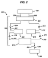
図2は、本発明による装置を使用するシステムの第1の代替実施形態の概略図である。図面はシステム300を示し、構成要素は、口腔内の液体の往復運動を提供する手段302、液体リザーバ370、液体供給リザーバ390、及び液体を口腔内の複数の表面上及びその周囲に方向付ける手段(この場合においては適用トレー100として示される)を含む。流体の往復運動を提供する手段としては、供給装置310、回収装置320、往復式流量制御装置330、管312、322、372、376及び392、並びに溶液一方向弁314、324、374、378及び394を含み得る。管332及び334は、往復式流量制御装置330から適用トレー100への液体の運搬を提供する。
FIG. 2 is a schematic diagram of a first alternative embodiment of a system using an apparatus according to the present invention. The drawing shows a
いくつかの実施形態において供給装置310及び回収装置320は、個別の単動ピストンポンプであり得る。他の実施形態において、供給装置310及び回収装置320は、複動ピストンポンプとして一緒に収容され得る。液体リザーバ390及び液体リザーバ370は、ガラス、プラスチック又は金属から作製され得る。液体供給リザーバ390は、システム300と一体であり、再充填可能であり得る。いくつかの実施形態において、液体供給リザーバ390は、システム300に取り外し可能に接続された交換可能な液体供給源であり得る。
In some embodiments, the
いくつかの実施形態において、液体供給リザーバ390、液体リザーバ370又は管312、372、392のいずれかが、口腔内の複数の表面に適用するために、適用トレー100内に方向付ける前に液体を予備加熱するための熱源を含み得る。温度は、使用中にユーザーに快適性を提供するために有効な範囲内に維持されるべきである。
In some embodiments, any of the
適用トレー100は、管332、334及び他の取り付け手段(図示されない)により、洗浄往復運動手段302と一体であるか又はこれに取り外し可能に接続され得る。
The
液体供給リザーバ390内の液体は、管392を通じて液体リザーバ370に流れる。リザーバ370内の液体は、管372を通じて供給装置310に流れる。管372を通じた液体流量は、一方向弁374によって制御される。供給装置310から、液体は管312を通じて往復式流量制御装置330に流れる。一方向弁314は、管312を通じた液体流量を制御する。液体は、流量制御装置330の流れ方向設定によって、管332又は334のいずれかを通じて往復式流量制御装置330から適用トレー100に流れる。液体は、適用トレー100から、管334又は332のいずれかを通じて往復式流量制御装置330に戻り、管322を通じて往復式流量制御装置330から供給/回収装置320に流れる。一方向弁324は、管322を通じた液体流量を制御する。最終的に洗浄液は、回収装置320から管376を通じて液体リザーバ370に流れる。一方向弁378は、管376を通じた液体流量を制御する。
The liquid in the
供給装置310及び回収装置320は、論理回路によって制御され、これは往復運動周期を開始するプログラム、往復運動周期を実行するプログラム(すなわち、溶液を口腔の複数の表面の周囲で往復運動させ、それによって口腔に有益効果を提供する)、往復運動周期及び、使用間、又はプリセット若しくは自動洗浄期間にシステムを洗浄するための自己洗浄周期の最後に適用トレー100を内容排出するプログラム含み得る。
The
システム300はまた、例えば、ON/OFF、適用トレー100の充填、洗浄プログラムの実行、システム300の内容排出、及びシステム300の洗浄などのスイッチ、並びに電源投入、充電、周期プログラムの実行、装置内容排出、結果又はフィードバック及び操作中の自己洗浄周期が挙げられるがこれらに限定されないインジケータ又はディスプレイライトを含み得る。適用トレー100への方向付けの前に液体が予備加熱される実施形態において、ディスプレイライトは、液体が使用のために適切な温度にあることを示すために使用され得る。
The
歯を洗浄するためにシステム300を使用する1つの方法は以下である。使用前に、液体供給チャンバ390内の洗浄液が、管392及び一方向弁394を通じて洗浄液リザーバ370に流れる。いくつかの実施形態において、液体供給リザーバ390はここでシステム300から分離される。
One method of using the
第1工程において、ユーザーは適用トレー100を口腔内で歯及び歯肉領域の周囲に位置付ける。ユーザーはトレー100を閉じ、それによって歯肉と、歯と、トレー100との間の効果的なフィット又は封止を達成する。ユーザーはスタートボタンを押して洗浄プロセスを開始する。洗浄プロセスは以下である。
1.供給装置310が起動されて、洗浄液を洗浄液リザーバ370から、管372及び一方向弁374を通じて引き始める。
2.一度供給/回収装置310が十分に充填されると、供給/回収装置310が起動されて、洗浄液を管312、一方向弁314、往復式流量制御装置330及び管332を通じて適用トレー100に分配し始める。
3.回収装置320が、供給装置310の起動の後に、又はこれと同時に起動されて、適用トレー100から、管334、往復式流量制御装置330、管322及び一方向弁324を通じて洗浄液を引き始める。一方向弁374により、洗浄溶液が管372を通じて流れるのを妨げられる。いくつかの実施形態において、供給装置310及び回収装置320は、論理回路により、同容量の流量が供給装置310から分配されて、回収装置320内に引かれるように、協調して機能するように制御される。
4.回収装置320は、管376及び一方向弁378を通じて、洗浄液リザーバ370への洗浄溶液の分配を開始するように起動される。一方向弁324により、洗浄液が管322を通じて流れることを妨げられる。供給装置310がまた起動されて、洗浄液を洗浄液リザーバ370から、管372及び一方向弁374を通じて引き始める。
5.洗浄液を往復運動させるため、流れ方向が逆転された後に工程2及び3が繰り返され、管334及び332をそれぞれ使用して供給/回収装置320と適用トレー100との間で洗浄液を循環させる。
6.洗浄液を循環させるため、工程2〜4が繰り返され、洗浄液リザーバ370と適用トレー100との間で洗浄液を循環させる。
7.洗浄に必要とされる時間が経過するまで、又は所望の周期数が達成されるまで、プロセスを実行し続ける。
In the first step, the user positions the
1.
2. Once the supply /
3. The
4). The
5. Steps 2 and 3 are repeated after the flow direction has been reversed to reciprocate the cleaning liquid, and the cleaning liquid is circulated between the supply /
6). In order to circulate the cleaning liquid, steps 2 to 4 are repeated, and the cleaning liquid is circulated between the cleaning
7). The process continues to run until the time required for cleaning elapses or until the desired number of cycles is achieved.
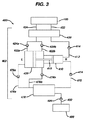
図3は、本発明による装置を使用するシステムの第2の代替実施形態の概略図である。図面はシステム400を示し、構成要素は、口腔内の液体の往復運動を提供する手段402、液体リザーバ470、液体供給リザーバ490、及び液体を口腔内の複数の表面上に方向付ける手段(この場合においては適用トレー100として示される)を含む。往復運動を提供する手段402としては、供給装置410、回収装置420、往復式流量制御装置430、管412、422a、422b、472、476及び492、並びに溶液一方向弁414、424a、424b、474、478a、478b及び494を含み得る。管432及び434は、往復式流量制御装置430から適用トレー100への液体の運搬を提供する。
FIG. 3 is a schematic diagram of a second alternative embodiment of a system using an apparatus according to the present invention. The drawing shows a
本実施形態において、供給装置410及び回収装置420は、複動ピストンポンプとして、共通ピストン415と共に一緒に収容される。液体リザーバ490及び液体リザーバ470は、ガラス、プラスチック又は金属から作製され得る。液体供給リザーバ490は、システム400と一体であり、再充填可能であり得る。いくつかの実施形態において、液体供給チャンバ490は、システム400に取り外し可能に接続された交換可能な液体供給源であり得る。
In this embodiment, the
いくつかの実施形態において、液体供給チャンバ490、液体リザーバ470又は管412、472、492のいずれかが、歯への適用のために適用トレー100内に方向付ける前に、洗浄溶液を予備加熱するための熱源を含み得る。温度は、使用中にユーザーに快適性を提供するために有効な範囲内に維持されるべきである。
In some embodiments, the
適用トレー100は往復運動手段402と一体であるか、又は管432、434及び他の取り付け手段(図示されない)により、これに取り外し可能に接続され得る。
The
液体供給チャンバ490内の液体は、管492を通じて液体リザーバ470に流れる。リザーバ470内の液体は、管472を通じて供給装置410に流れる。管472を通じた液体流量は、一方向弁474によって制御される。供給装置410から、液体は管412を通じて往復式流量制御装置430に流れる。一方向弁414は、管412を通じた液体流量を制御する。液体は、流れ方向によって、管432又は管434を通じて往復式流量制御装置430から適用トレー100に流れる。液体はやはり流れ方向によって、適用トレー100から管434又は管432を通じ、往復式流量制御装置430に戻り、往復式流量制御装置430から管422a及び422bを通じて回収装置420へと流れる。一方向弁424a及び424bは、管を通じた流量を制御する。最終的に、液体は回収装置420から管476a及び476bを通じて液体リザーバ470へと流れる。一方向弁478a及び478bは、管を通じた流量を制御する。
Liquid in the
供給装置410及び回収装置420は、論理回路によって制御され、これは往復運動周期を開始するプログラム、往復運動周期を実行するプログラム(すなわち、溶液を口腔の複数の表面の周囲で往復運動させ、それによって口腔に有益効果を提供する)、この周期及び、使用間又はプリセット若しくは自動洗浄期間にシステムを洗浄するための自己洗浄周期の最後に適用トレー100を内容排出するプログラム含み得る。
The
システム400はまた、例えば、ON/OFF、適用トレー100の充填、洗浄プロセスの実行、システム400の内容排出、及びシステム400の洗浄などのスイッチ、並びに洗浄周期並びに電源投入、充電、周期プログラムの実行、装置内容排出、及び操作中の自己洗浄周期が挙げられるがこれに限定されないインジケータ又はディスプレイライトを含み得る。適用トレー100への方向付けの前に液体が予備加熱される実施形態において、ディスプレイライトは、液体が使用のために適切な温度にあることを示すために使用され得る。
The
歯を洗浄するためにシステム400を使用する1つの方法は以下である。使用前に、供給リザーバ490内の洗浄液が管492及び一方向弁494を通じて洗浄液リザーバ470に流れる。いくつかの実施形態において、液体供給リザーバ490はここでシステム400から分離される。
One method of using the
第1工程において、ユーザーは適用トレー100を口腔内で歯及び歯肉領域の周囲に位置付ける。ユーザーはトレー100を閉じ、それによって歯肉と、歯と、トレー100との間の効果的なフィット又は封止を達成する。ユーザーはスタートボタンを押して洗浄プロセスを開始する。洗浄プロセスは以下である。
1.ピストン415が起動されて、洗浄液を洗浄液リザーバ470から、管472及び一方向弁474を通じて供給装置410に引き始める。これを達成するため、ピストン415は右から左へと平行移動する(図3の「R」から「L」)。
2.一度供給/回収装置410が十分に充填されると、供給/回収装置410が起動されて、洗浄液を管412、一方向弁414、往復式流量制御装置430及び管432を通じて適用トレー100に分配し始める。これを達成するため、ピストン415は左から右へと平行移動する(図3の「L」から「R」)。ピストン415の「L」から「R」への動きにより、回収装置420は、管434、往復式流量制御装置430、管422a及び一方向弁424aを通じて適用トレー100から洗浄液を引き始める。洗浄液は、一方向弁474及び424bにより、管472及び422aを通じて流れるのを妨げられる。回収装置420内のあらゆる過剰な洗浄液は、管476b及び一方向弁478bを通じて洗浄液リザーバ470へと分配され始める。一方向弁424bにより、洗浄液が管422bを通じて流れることが防がれる。
3.洗浄溶液を循環させるため、工程1及び2が繰り返され、洗浄溶液リザーバ470と適用トレー100との間で洗浄液を循環させる。
4.洗浄に必要とされる時間が経過するまで、又は所望の周期数が達成されるまで、プロセスを実行し続ける。
In the first step, the user positions the
1. The
2. Once the supply /
3. In order to circulate the cleaning solution, steps 1 and 2 are repeated to circulate the cleaning solution between the
4). The process continues to run until the time required for cleaning elapses or until the desired number of cycles is achieved.
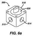
図1、図2及び図3に記載される各実施形態は、往復式流量制御装置(それぞれ図1、図2、図3の230、330、430)。本発明による往復式流量制御装置の実施形態の斜視図及び分解図が、それぞれ図6a及び図6bに示される。図面は、ハウジング510及び分流器520を有する往復式流量制御装置500を示す。ハウジング510は、ポート514、515、516及び517を有する。分流器520は、ハウジング510の内側壁部によって画定される空間を占め、流体流れを分流するためのパネル522及び位置調節器524を有する。
Each of the embodiments described in FIGS. 1, 2 and 3 is a reciprocating flow control device (230, 330 and 430 in FIGS. 1, 2 and 3, respectively). A perspective view and an exploded view of an embodiment of a reciprocating flow control device according to the present invention are shown in FIGS. 6a and 6b, respectively. The drawing shows a reciprocating
図6cは、その第1位置にある往復式流量制御装置500の断面図である。この位置において、図1の管212の液体などの、流入する液体流532が、ポート515を通じて往復式流量制御装置500に入る。この液体は、流出する液体流534として(すなわち、図1の管232内の液体)ポート514を通じて往復式流量制御装置500を出る。図1の管234内の液体などの、戻る液体流536が、ポート517を通じて往復式流量制御装置500に再び入る。この液体は、流出する液体流538として(すなわち、図1の管216内の液体)ポート516を通じて往復式流量制御装置500を出る。
FIG. 6c is a cross-sectional view of the reciprocating
図6dは、その第2位置にある往復式流量制御装置500の断面図である。この位置において、図1の管212の液体などの、流入する液体流532が、ポート515を通じて往復式流量制御装置500に入る。この液体は、流出する液体流534として(すなわち、図1の管234内の液体)ポート516を通じて往復式流量制御装置500を出る。図1の管232内の液体などの、戻る液体流536が、ポート517を通じて往復式流量制御装置500に再び入る。この液体は、流出する液体流538として(すなわち、図1の管216内の液体)ポート514を通じて往復式流量制御装置500を出る。
FIG. 6d is a cross-sectional view of the reciprocating
図1の適用トレー100の液体の往復運動は、往復式流量制御装置500をその第1位置と第2位置との間で切り替えることによって達成される。
The reciprocating movement of the liquid in the
本発明による往復式流量制御装置の第1の代替実施形態の斜視図が図7aに示される。図は、ハウジング560、流量制御ブロック570及び設定ピン580を有する往復式流量制御装置550を示す。ハウジング560は、ポート564、565、566及び567を有する。流量制御ブロック570は、ハウジング560の内側壁部によって画定される空間を占め、液体流を分流するための経路又は導管571、572、573及び574を有する。
A perspective view of a first alternative embodiment of a reciprocating flow control device according to the present invention is shown in FIG. 7a. The figure shows a reciprocating
図7bは、その第1位置にある(設定ピン580が「out」位置にある)流量制御装置550の平面図である。第1位置において、図1の管212の液体などの、流入する液体流592が、ポート564を通じて往復式流量制御装置550に入る。液体は、制御ブロック570の経路573を通じて流れ、流出する液体流594として(すなわち、図1の管232内の液体)ポート566を通じて往復式流量制御装置550を出る。図1の管234内の洗浄液などの、戻る液体流596が、ポート567を通じて往復式流量制御装置550に再び入る。液体流は、制御ブロック570の経路571を通じて流れ、流出する液体流598として(すなわち、図1の管216内の液体)ポート565を通じて往復式流量制御装置550を出る。
FIG. 7b is a plan view of the
図7cは、その第2位置にある(設定ピン580が「in」位置にある)流量制御装置550の平面図である。第2位置において、図1の管212の液体などの、流入する液体流592が、ポート564を通じて往復式流量制御装置550に入る。液体流は、制御ブロック570の経路574を通じて流れ、流出する液体流594として(すなわち、図1の管234内の液体)ポート567を通じて往復式流量制御装置550を出る。図1の管232内の液体などの、戻る液体流596が、ポート566を通じて往復式流量制御装置550に再び入る。液体流は、制御ブロック570の経路572を通じて流れ、流出する液体流598として(すなわち、図1の管212内の液体)ポート565を通じて往復式流量制御装置550を出る。
FIG. 7c is a plan view of the
図1の適用トレー100の液体の往復運動は、往復式流量制御装置550をその第1位置と第2位置との間で切り替えることによって達成される。
The reciprocating movement of the liquid in the
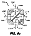
本発明による往復式流量制御装置の第2の代替実施形態の分解図、加えて斜視図が図8a及び図8bにそれぞれ示される。図面は、ハウジング620及び流量制御バレル630を備える往復式流量制御装置610を示す。ハウジング620はポート621、622、623及び624を有する。流量制御バレル630は、ハウジング620の内側壁部によって画定される空間を占め、液体流を分流するための経路633、634、635及び636、並びに位置調節器632を有する。
An exploded view and a perspective view of a second alternative embodiment of a reciprocating flow control device according to the present invention are shown in FIGS. 8a and 8b, respectively. The drawing shows a reciprocating
図8cは、その第1位置にある往復式流量制御装置610の側面図である。第1位置において、流入する液体流がポート621を通じて往復式流量制御装置610に入る。液体は、制御バレル630の経路634を通じて流れ、ポート623を通じて往復式流量制御装置610を出る。戻る液体が、ポート624を通じて往復式流量制御装置610に再び入る。液体は、制御バレル630の経路633を通じて流れ、ポート622を通じて往復式流量制御装置610を出る。
FIG. 8c is a side view of the reciprocating
図示されないが、往復式流量制御装置610は、位置調節器632を90°回転させることによって、その第2位置に配置され得る。第2位置において、流入する液体流がポート621を通じて往復式流量制御装置610に入る。液体は、制御バレル630の経路636を通じて流れ、ポート624を通じて往復式流量制御装置610を出る。戻る液体が、ポート623を通じて往復式流量制御装置610に再び入る。液体は、制御バレル630の経路636を通じて流れ、ポート622を通じて往復式流量制御装置610を出る。
Although not shown, the
図1、2又は3の適用トレー100の液体の往復運動は、往復式流量制御装置610をその第1位置と第2位置との間で切り替えることによって達成される。
The reciprocating movement of the liquid in the
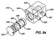
本発明による往復式流量制御装置の第3の代替実施形態の斜視図及び分解図が、それぞれ図9a及び図9bに示される。図面は、キャップ720、分流ディスク730及び基部740を備える往復式流量制御装置710を示す。キャップ720は、キャップポート722及び724を有する。基部740は、基部ポート742及び744を有する。分流ディスク730は、キャップ720と基部740との間に配置され、液体流を分流するためのパネル735及び歯車の形態の位置調節器732を有する。
A perspective view and an exploded view of a third alternative embodiment of a reciprocating flow control device according to the present invention are shown in FIGS. 9a and 9b, respectively. The drawing shows a reciprocating
図9cは、その第1位置にある往復式流量制御装置710の平面図である。この位置において、図1の管212の液体などの、流入する液体流が、基部ポート742を通じて往復式流量制御装置710に入る。図1の管232の液体などの液体が、キャップポート722を通じて往復式流量制御装置710を出る。図1の管234の液体などの戻る流体が、キャップポート724を通じて往復式流量制御装置710に再び入る。図1の管216の液体などの液体が、基部ポート744を通じて往復式流量制御装置710を出る。
FIG. 9c is a plan view of the reciprocating
図9dは、その第2位置にある往復式流量制御装置710の平面図である。この位置において、図1の管212の液体などの、流入する液体流が、基部ポート742を通じて往復式流量制御装置710に入る。図1の管234の液体などの液体が、キャップポート724を通じて往復式流量制御装置710を出る。図1の管232の液体などの戻る流体が、キャップポート722を通じて往復式流量制御装置710に再び入る。図1の管216の液体などの液体が、基部ポート744を通じて往復式流量制御装置710を出る。
FIG. 9d is a plan view of the
図1の適用トレー100の液体の往復運動は、往復式流量制御装置710をその第1位置と第2位置との間で切り替えることによって達成される。キャップポート722及び724、並びに基部ポート742及び744の直径に対するパネル735の幅が、往復式流量制御装置710の性能にとって重要であることが見出された。パネル735の幅が、いずれかの直径と同等以上である場合、キャップポート722及び724、並びに基部ポート742及び744の1つ以上が、往復運動の一部の間において、遮蔽又は分離される場合があり、最適以下の性能又は装置の故障を生じる。この状態を回避するために、パネル735内にチャネルが位置してもよい。
The reciprocating movement of the liquid in the
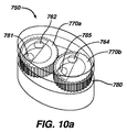
本発明による往復式流量制御装置の第4の代替実施形態の斜視図及び側面図が、それぞれ図10a及び図10bに示される。図面は、キャップ760、分流ディスク770及び基部780を備える往復式流量制御装置750を示す。キャップ760は、キャップポート762及び764を有する。基部780は、基部上ポート781、782、784及び785、並びに基部下ポート783及び786を有する。基部上ポート781及び782は合流して基部下ポート783を形成し、基部上ポート784及び785は合流して基部下ポート786を形成する。分流器770はキャップ760と基部780との間に配置され、液体流を分流するための二重ギア770a及び770bを有する。
A perspective view and a side view of a fourth alternative embodiment of a reciprocating flow control device according to the present invention are shown in FIGS. 10a and 10b, respectively. The drawing shows a
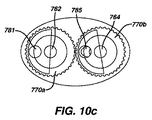
図10cは、その第1位置にある往復式流量制御装置750の平面図である。この位置において、図1の管212の液体などの流入する液体は、基部下ポート783を通じて往復式流量制御装置750に入り、一方で基部上ポート784は遮蔽される。歯車770aは、液体が基部上ポート781を通じて基部780を出るように設定される。図1の管232の液体などの液体が、キャップポート762を通じて往復式流量制御装置750を出る。図1の管234の液体などの戻る流体が、キャップポート764を通じて往復式流量制御装置750に再び入る。歯車770bは、液体が基部上ポート785を通じて基部780に入るように設定される。図1の管216の液体などの液体が、基部ポート786を通じて往復式流量制御装置750を出る。
FIG. 10c is a plan view of the reciprocating
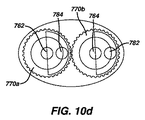
図10dは、その第2位置にある往復式流量制御装置750の平面図である。この位置において、図1の管212の液体などの、流入する液体流が、基部ポート783を通じて往復式流量制御装置750に入る。歯車770bは、基部上ポート785が遮蔽される間に、基部上ポート782を通じて基部780を出るように設定される。図1の管234の液体などの液体が、キャップポート764を通じて往復式流量制御装置710を出る。図1の管232の液体などの戻る流体が、キャップポート762を通じて往復式流量制御装置750に再び入る。歯車770aは、基部上ポート781が遮蔽される間に、基部上ポート784を通じて基部780に入るように設定される。図1の管216の液体などの液体が、基部ポート786を通じて往復式流量制御装置750を出る。
FIG. 10d is a plan view of the
図1の適用トレー100の液体の往復運動は、往復式流量制御装置750をその第1位置と第2位置との間で切り替えることによって達成される。第1位置と第2位置との間にあるとき、流れの交差により最適以下の動作又は装置の故障を生じ得る、流れの遮蔽が排除される。
The reciprocating movement of the liquid in the
本発明による往復式流量制御装置の第5の代替実施形態の斜視図が図11aに示される。図は、流路831、832、833、834、835、836、837及び838並びに分流器820を備える往復式流量制御装置810を示す。流路831は、分岐して流路832及び833を形成する。流路834は分岐して流路835及び836を形成する。流路833及び836は合流して流路837を形成し、流路832及び835は合流して流路838を形成する。分流器820は、流路831、832、833、834、835、836、837及び838に隣接するように配置され、かつロッド822、ドライバ824、並びに液体流を分流するための流量制御要素825、826、827及び828を有する。
A perspective view of a fifth alternative embodiment of a reciprocating flow control device according to the present invention is shown in FIG. 11a. The figure shows a
図11bは、その第1位置にある往復式流量制御装置810の平面図である。ドライバ824は、流量制御要素825及び828がそれぞれチャネル833及び835を通じた液体の流れを阻止する一方で、流量制御要素826及び827がそれぞれチャネル836及び832を通じた流れを可能にするように設定される。この位置において、図1の管212の液体などの流入する液体は、流路831を通じて往復式流量制御装置810に入る。液体は流路832を通じ、流路838へと流れる。図1の管232の液体などの液体が、流路838を通じて往復式流量制御装置810を出る。図1の管234の液体などの戻る流体が、流路837を通じて往復式流量制御装置810に再び入る。図1の管216内の液体など、液体は流路836を通じ、流路834へと流れ、流路834を通じて往復式流量制御装置810を出る。
FIG. 11b is a plan view of the reciprocating
図11cは、その第2位置にある往復式流量制御装置810の平面図である。ドライバ824は、流量制御要素826及び827がそれぞれチャネル836及び832を通じた流れを阻止する一方で、流量制御要素828及び825がそれぞれチャネル833及び835を通じた液体の流れを可能にするように設定される。この位置において、図1の管212の液体などの流入する液体は、流路831を通じて往復式流量制御装置810に入る。液体は流路833を通じ、流路837内へと流れる。図1の管234の液体などの液体が、流路837を通じて往復式流量制御装置810を出る。図1の管232の液体などの戻る流体が、流路838を通じて往復式流量制御装置810に再び入る。図1の管216内の液体など、液体は流路835を通じ、流路834へと流れ、流路834を通じて往復式流量制御装置810を出る。
FIG. 11c is a plan view of the reciprocating
図1の適用トレー100の洗浄液の往復運動は、往復式流量制御装置810をその第1位置と第2位置との間で切り替えることによって達成される。
The reciprocating motion of the cleaning liquid of the
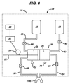
図4は、本発明による装置を使用するシステムの別の代替実施形態の概略図である。図示されるように、システム10は口腔の複数の表面上に流体を方向付けるための手段(この場合、適用トレー100として示され、ハウジング12内に収容される)、位置センサー24と係合するピストン22を有するピストンポンプ20、論理回路30、電源32、液体供給リザーバ40、液体保持リザーバ42、管52、54、56、58、液体流弁62、64、66、68及び圧力変換器72、74を含む。
FIG. 4 is a schematic diagram of another alternative embodiment of a system using an apparatus according to the present invention. As shown, the
ハウジング12は、必要な構成要素を保持することができ、必要なコネクタを保持するための手段である。システム10が手持ち式の大きさである実施形態において、ハウジング12は充電基部ステーションに機械的かつ電気的に係合する。
The
示される実施形態において、ポンプ20は複動ピストンポンプの形態で示されるが、一対の単動ポンプ又は他の同等のポンプが使用され得ることが想到される。ポンプが複動ピストンポンプである場合、ポンプはピストン22、第1チャンバ26及び第2チャンバ28を含む。ピストン22は、位置センサー24と係合する。圧力変換器72、74はそれぞれ、第1チャンバ26及び第2チャンバ28の圧力を測定する。
In the embodiment shown, the
液体供給リザーバ40及び液体保持リザーバ42は、ガラス、プラスチック又は金属から作製され得る。供給リザーバ40は、ハウジング12と一体であり、再充填可能であり得る。いくつかの実施形態において、供給チャンバ40は、ハウジング12に取り外し可能に接続された、置換可能な溶液供給源であり得る。保持リザーバ42は、周期(例えば、洗浄周期)の最後に使用された溶液を保存するために使用される。保持リザーバ42はまた、使用された溶液を排出するためのポート又は他の手段(図示されない)を含み得る。
The
以下で記載されるように、管52、54、56、58及び液体流弁62、64、66、68は、ポンプ20、液体供給チャンバ40、液体保持リザーバ42及び適用トレー100を接続する。
As described below,
いくつかの実施形態において、供給リザーバ40及び/又は管52、54は、口腔の複数の表面に適用するために、適用トレー100に方向付ける前に液体を予備加熱するための熱源を含み得る。温度は、使用中にユーザーに快適性を提供するために有効な範囲内に維持されるべきである。
In some embodiments,
電源32は、電気的であり、すなわち置換可能又は充電可能な電池の形態であり得る。
The
適用トレー100はハウジング12と一体であるか、管54、56及び他の取り付け手段(図示されない)により、これに取り外し可能に接続され得る。これは食物微粒子を捕捉するための、容易に洗浄可能なフィルターを内部に備え、1又は2つの側部を有し得る。更に、歯に適用される際、トレー100は、歯肉に対して効果的なフィット又は封止を形成し、口腔の表面に対して液体を方向付けるための手段を含む。
The
使用中、供給リザーバ40内の液体が第1管52を通じてポンプ20の第1チャンバ26に流れる。第1管52を通じた液体流は、第1弁62によって制御される。液体流は、ポンプ20の第1チャンバ26から、第2管54を通じて適用トレー100に流れる。第2弁64は、第2管54を通じた液体流を制御する。液体流は、適用トレー100から、第3管56を通じ、ポンプ20の第2チャンバ28に流れ、第3弁66によって制御される。ポンプ20の第2チャンバ28は、第4管58によって保持リザーバ42に接続する。第4管58を通じた液体流は、第4弁68によって制御される。
During use, the liquid in the
論理回路30は、周期の開始時に適用トレー100を液体で充填させるプログラムと、周期を実行する、すなわち、液体を口腔の複数の表面(例えば、歯及び歯肉)の周囲で往復運動させ、それによって有益効果(例えば、歯の洗浄)を提供するプログラムと、この周期及び、使用間又はプリセット若しくは自動洗浄期間にシステムを洗浄するための自己洗浄周期の最後に適用トレー100を内容排出するプログラムとを含み得る。論理回路30は、液体の漏れを検出する手段、加えて周期中に比較的一定の容積の液体を保持するために、漏れを補充する手段を含む。図4に示される実施形態において、液体の漏れを検出する手段は、第1チャンバ26及び第2チャンバ28内にそれぞれ位置する圧力変換器72、74を使用する。
The
図示されないが、一連のスイッチ及びインジケータライトを有するフェースパネルがまた、システム10内に組み込まれ得る。スイッチは、ON/OFF、適用トレー100の充填、往復運動プログラムの実行、システム10の内容排出及びシステム10の洗浄を含むがこれに限定されない。インジケータ、ディスプレイライトは、電源投入、充電、往復運動プログラムの実行、システム内容排出、洗浄結果又はフィードバック及び操作中の自己洗浄周期を含む。適用トレー100への方向付けの前に洗浄液が予備加熱される実施形態において、ディスプレイライトは、液体が使用のために適切な温度にあることを示すために使用され得る。
Although not shown, a face panel having a series of switches and indicator lights can also be incorporated into the
歯を洗浄するためにシステム10を使用する1つの方法は以下である。第1工程において、ユーザーは適用トレー100を口腔内で歯及び歯肉領域の周囲に位置付ける。ユーザーはトレー100を閉じることによって圧力を適用し、それによって歯肉と、歯と、トレー100との間の効果的なフィット又は封止を達成する。ユーザーは、スタートボタンを押して、トレー100の表面と洗浄される歯との間に画定される空間への、洗浄溶液の充填を開始する。論理回路30は、以下の洗浄プロセスを制御する。
1.第1弁62が開き、第2弁64が閉じ、ピストン22がその一番左の位置まで移動し、供給リザーバ40から第1管52を通じてポンプ20の第1チャンバ26内へと液体を引く。
2.第1弁62が閉じる一方で、第2弁64、第3弁66及び第4弁68が開く。ピストン22がその一番右の位置まで移動し、第2管54を通じて適用トレー100へと液体を推進する。
3.適切にシステムを充填するため、圧力変換器72、74両方で既定の圧力が検出され、適切な量の液体がチャンバ26及び28内に収容されたことを示すまで、上記のように工程1及び工程2が繰り返され、液体をポンプ移送する。チャンバ26及び28は、量が使用中の適用トレーを通じた及び口腔の複数の表面の周囲の液体の往復運動を維持するために効果的である限りにおいて、完全に又は部分的に充填され得る。
4.第1弁62及び第4弁68が閉じる一方で第2弁64及び第3弁66は開いたままである。
5.ピストン22は、その左から右の位置、及びその反対へと周期移動し、液体を表面(例えば、適用トレー100内の歯)にわたって前後に循環させるように促進する。
6.圧力変換器72又は74のいずれかによって圧力の損失が検出される場合、工程1〜3が繰り返されて、ポンプ20の第1チャンバ26及び第2チャンバ28の液体の適切な容積を維持する。
7.有益効果(例えば、洗浄)を達成するために必要な時間が経過するまで、周期が完了するまで、又はシステムが圧力を増加させることなく多数回循環し、液体源が使い果たされたことを示すまで、プロセスを実行し続ける。
One method of using the
1. The
2. While the
3. To properly fill the system, a predetermined pressure is detected at both
4). While the
5.
6). If pressure loss is detected by either
7). That the liquid source has been exhausted until the time necessary to achieve a beneficial effect (eg, cleaning) has elapsed, the cycle has been completed, or the system has been cycled many times without increasing pressure. Continue to run the process until shown.
適用トレー100に入る前に液体が予備加熱される実施形態において、温度センサーが回路内に組み込まれてユーザーに溶液が使用するためには冷たすぎることを警告し、溶液の加熱方法が提供される。
In embodiments where the liquid is preheated before entering the
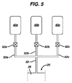
いくつかの実施形態において、図5に示されるように、多数の液体源が使用され得る。図は、システム10の液体供給部分のみを示す(図4)。論理回路30は以下のプロセスを制御する。
1.第1弁62aが開き、弁62b、62c及び第2弁64が閉じ、ピストン22がその一番左の位置まで移動し、供給リザーバ40aから、管52a及び52を通じ、ポンプ20の第1チャンバ26へと液体を引く。
2.第1弁62aが閉じる一方で第2弁64、第3弁66及び第4弁68が開く。ピストン22がその一番右の位置まで移動し、第2管54を通じて適用トレー100へと液体を推進する。
3.システムを完全に充填するため、工程1及び2が繰り返され、圧力が両方の圧力変換器72、74で検出されるまで液体をポンプ移送する。
4.第1弁62及び第4弁68が閉じる一方で第2弁64及び第3弁66は開いたままである。
5.ピストン22は、その左から右の位置へと周期移動し、液体を適用トレー100の口腔の表面にわたって前後に循環するように促進する。
6.圧力変換器72又は74のいずれかで圧力損失する場合、ポンプ20の第1チャンバ26及び第2チャンバ28内で圧力が回復される際に工程1〜3が繰り返されてシステムを再充填する。
7.時間が経過するか、周期が完了するか、又はシステムが圧力を増加させることなく多数回循環し、液体源が使い果たされたことを示すまで、プロセスを実行し続ける。
8.第1弁62aが閉じ、弁62bが開き、弁62cは閉じたままであり、工程1〜7が繰り返され、液体は供給リザーバ40b内にある。
9.第1弁62aが閉じたままであり、弁62bが閉じ、弁62cが開き、工程1〜7が繰り返されて、洗浄溶液は液体供給リザーバ40cにある。
In some embodiments, multiple liquid sources can be used, as shown in FIG. The figure shows only the liquid supply portion of the system 10 (FIG. 4). The
1. The first valve 62a opens, the
2. While the first valve 62a is closed, the
3. To completely fill the system, steps 1 and 2 are repeated, pumping liquid until pressure is detected at both
4). While the
5. The
6). If there is a pressure loss in either
7). The process continues to run until time passes, the cycle is complete, or the system circulates many times without increasing pressure, indicating that the liquid source has been exhausted.
8). The first valve 62a closes, the
9. The first valve 62a remains closed, the
この手順は、各供給リザーバに追加的に液体を供給して、無制限に繰り返され得ることに留意するのが重要である。加えて、最終的な液体供給リザーバは水又は他の洗浄液を含んでもよく、かつシステムは洗浄のためにパージされ得る。 It is important to note that this procedure can be repeated indefinitely, supplying additional liquid to each supply reservoir. In addition, the final liquid supply reservoir may contain water or other cleaning liquid and the system may be purged for cleaning.
口腔衛生システムは、基部ステーション、口腔内の複数の表面の周囲の液体の前後運動を提供する手段を含むハンドピース、及び適用トレー又はマウスピースが挙げられるがこれらに限定されないいくつかの主要構成要素を含み得る。システムは家庭用の用途に好適であり、歯の複数の表面上に液体を同時に方向付けるように適合される。装置は洗浄溶液を使用して歯を洗浄し、かつ歯垢を除去し、洗浄溶液は前後に往復運動されて、洗浄周期を生じ、使用する洗浄溶液を最小化する。装置は、手持ち式であり得、又は卓上若しくはカウンタートップ装置の形態であり得る。 An oral hygiene system includes several main components including, but not limited to, a base station, a handpiece including means for providing back and forth movement of liquid around a plurality of surfaces in the oral cavity, and an application tray or mouthpiece Can be included. The system is suitable for home use and is adapted to direct liquid on multiple surfaces of the tooth simultaneously. The device uses the cleaning solution to clean the teeth and removes plaque, and the cleaning solution is reciprocated back and forth to create a cleaning cycle and minimize the cleaning solution used. The device can be handheld or can be in the form of a tabletop or countertop device.
基部ステーションは、ハンドピース内の再充電電池を充電し、液体リザーバを保持し、診断構成要素を収容し、ユーザーにフィードバックを提供し、場合によりマウスピースを洗浄する。 The base station charges the rechargeable battery in the handpiece, holds the liquid reservoir, contains the diagnostic components, provides feedback to the user, and optionally cleans the mouthpiece.
ハンドピースは、リザーバからマウスピースに液体を供給する駆動ポンプを有する。流れ方向は、専用ポンプ(その方向を逆転するなど)、可逆性逆止弁又は他の同様の手段による液体制御弁調節で、往復運動し得る。周期の各段階における周期時間及び流速は可変であり、いくつかの実施形態においては、各個別のユーザーに対してカスタマイズされる。ハンドピースは、充填プロセス、並びに洗浄及び/又はパージプロセスを実行する。ハンドピース及び/又は基部ステーションはプロセスの各段階においてユーザーにフィードバックを提供してもよく、場合によって診断情報を報告してもよい。 The handpiece has a drive pump that supplies liquid from the reservoir to the mouthpiece. The direction of flow may reciprocate with a liquid control valve adjustment by a dedicated pump (such as reversing the direction), a reversible check valve or other similar means. The cycle time and flow rate at each stage of the cycle are variable and, in some embodiments, customized for each individual user. The handpiece performs a filling process and a cleaning and / or purging process. The handpiece and / or base station may provide feedback to the user at each stage of the process and may optionally report diagnostic information.
ハンドピースは審美的に心地の良いものであり、ユーザーの手にとって快適な把持/感触を有する。重量及びバランスは、高質の感触を提供する一方で快適かつ効率的な使用に良好に適している。快適性、把持、感触、並びにハンドピースの適切な位置付け及び把持位置の補助のために、指グリップ及び/又はタッチポイントが適切に位置付けられる。基部ステーションはまた、審美的に心地良いものでありハンドピースが容易かつ確実に適所に結合することを可能にする。基部ステーションは、ハンドピースが一度結合されるとこれを適所に固定しても、しなくてもよい。 The handpiece is aesthetically pleasing and has a comfortable grip / feel for the user's hand. The weight and balance are well suited for comfortable and efficient use while providing a high quality feel. Finger grips and / or touch points are properly positioned for comfort, grip, feel, and proper positioning of the handpiece and assisting in the grip position. The base station is also aesthetically pleasing and allows the handpiece to be easily and reliably joined in place. The base station may or may not lock the handpiece once in place.
装置の第3の主要構成要素は、適用トレー又はマウスピースである。 The third major component of the device is an application tray or mouthpiece.
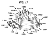
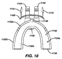
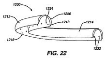
図12は、本発明による装置と共に使用される、適用トレー100などの口腔の複数の表面に液体を向けるための手段の第1実施形態の平面斜視図である。図13は、図12の適用トレー100の底面斜視図である。図面は、外側前方壁部112、外側後方壁部114、内側前方壁部116、内側後方壁部118及び基底膜(例えば、バイトプレート156)を有する適用トレー100を示す。内側前方壁部ジェットスロット132は、内側前方壁部116上に位置し、一方で内側後方壁部ジェットスロット134は、内側後方壁部118上に位置する。図12及び図13に示される内側前方壁部ジェットスロット132及び内側後方壁部ジェットスロット134は、ジェットスロット構成の単に一実施形態である。第1ポート142及び第2ポート144は、外側前方壁部112を通じて適用トレー100に入る。
FIG. 12 is a top perspective view of a first embodiment of a means for directing liquid to multiple surfaces of the oral cavity, such as the
図12及び図13は、適用トレー100の実施形態を表し、ここでユーザーの上の歯及び下の歯並びに/又は歯肉領域は、所望の有益効果を提供するために液体と実質的に同時に接触する。他の実施形態において、適用トレー100は、ユーザーの上の歯若しくは下の歯及び/又は歯肉領域のみを洗浄及び/又は処理するように設計され得ることが理解される。
FIGS. 12 and 13 represent an embodiment of an
図14及び図15はそれぞれ、図12の適用トレー100の垂直及び水平の断面図である。図面は、外側前方壁部112及び内側前方壁部116によって境界される空間として画定される第1マニホールド146を示す。第2マニホールド148は、外側後方壁部114及び内側後方壁部118によって境界される空間として画定される。液体接触チャンバ(LCC)154は、内側前方壁部116、内側後方壁部118、及び基底膜156によって画定される。
14 and 15 are vertical and horizontal sectional views of the
動作の一実施形態において、液体が圧力により第1ポート142を通じて第1マニホールド146に入り、その後、内側前方壁部ジェットスロット132を通じてLCC 154に入る。真空が第2ポート144上で引かれ、内側後方壁部ジェットスロット134を通じ、第2マニホールド148内及び最終的には第2ポート144内に液体を引く。この実施形態において、液体ジェットは、LCC 154の一方の側部から、歯及び/又は歯肉領域の前方表面へと向けられ、LCC 154の他方の側部から第2マニホールドへと、歯及び/又は歯肉領域の表面を通じて、その間及びその周囲に方向付けられ、制御された、歯間、歯茎ライン、表面及び/又は歯肉領域の洗浄又は処理を提供する。次に、マニホールド内の流れが逆転される。洗浄液は、圧力によって第2ポート144を通じて第2マニホールド148に入り、その後、内側後方壁部ジェットスロット134を通じてLCC 154に入る。真空が第1ポート142上で引かれて、内側前方壁部ジェットスロット132を通じて第1マニホールド146、及び最終的には第1ポート142内に液体を引く。この実施形態の第2部分において、液体ジェットは歯及び/又は歯肉領域の後方表面上に方向付けられ、歯及び/又は歯肉領域の表面を通じ、この間及び周囲に方向付けられる。多くの周期を通じた交互の圧力/真空は、乱流の、反復可能の及び可逆の流れを生じ、口腔の複数の表面付近に液体の往復運動を提供し、口腔の表面と液体とを実質的に同時に接触させ、それによって所望の有益効果を提供する。
In one embodiment of operation, liquid enters the
別の実施形態において、一方又は両方のマニホールドを通じて液体を同時に供給し、LCC 154に大量の液体送り、一定時間にわたって歯を浸漬し、その後、一定時間の後に一方又は両方のマニホールドを通じてLCC 154を空にすることが好ましい場合がある。ここで、洗浄液又は処理液は圧力により、第1ポート142を通じて第1マニホールド146に、第2ポート144を通じて第2マニホールド148に入り、その後、内側前方壁部ジェットスロット132及び内側後方壁部ジェットスロット134を通じて同時にLCC 154に入る。LCC 154を空にするため、第1ポート142を通じて第1マニホールド146に、第2ポート144を通じて第2マニホールド148に、真空が同時に引かれる。洗浄又は処理液は、内側前方壁部ジェットスロット132及び内側後方壁部ジェットスロット134を通じて、第1マニホールド146及び第2マニホールド148に引かれる。
In another embodiment, liquid is supplied simultaneously through one or both manifolds, a large amount of liquid is fed into the
第1マニホールド146及び第2マニホールド148に異なる液体組成物を供給することがまた可能である。改善された洗浄有効性又は処理効果のために、異なる液体組成物が、その後、LCC内で混合し得る。
It is also possible to supply different liquid compositions to the
図16は、本発明による装置と共に使用される適用トレー1100の第2実施形態の平面、後方斜視図である。図17は図16の適用トレー1100の前方斜視図であり、図18は図16の適用トレーの平面図である。図面は適用トレー1100を示し、上部1102、底部1104、第1部分1142、第2部分1144及び上記適用トレーの前部にしっかりと取り付けられた支持プレート1108を有する。第1部分1142及び第2部分1144は、適用トレー1100に入り、支持プレート1108を通じて延びる。
FIG. 16 is a plan, rear perspective view of a second embodiment of an
任意の急速脱着構造(例えば、返し部)1110が支持プレート1108に取り付けられ、適用トレー1100を、適用トレーに液体を提供する手段(例えば、図4に示されるような、装置10のハウジング12に収容され得る)に急速及び容易に取り付け、その後、分離することを可能にする。ハウジングは、このような急速脱着返し部又は同様の急速脱着構造を取り付け可能な係合により受容するために効果的な構造を含み、これは適用トレーをハウジングに取り外し可能に接続する。使用された若しくは着用された適用トレーを置換するため、又は別のユーザーのために適用トレーを交換するために、急速脱着オプションは使用され得る。いくつかの実施形態において単一のユーザーが、異なるオプションの流れ特性、例えば、洗浄ノズルの数、ノズル速度、スプレーパターン及び位置、適用範囲など、を変更するために、適用トレーを交換し得る。
An optional rapid desorption structure (eg, barb) 1110 is attached to the
図16〜19は、適用トレー1100の実施形態を表し、ここでユーザーの上の歯及び下の歯並びに/又は歯肉領域は、液体と実質的に同時に接触する。他の実施形態において、適用トレー1100は、ユーザーの上の歯若しくは下の歯又は歯肉領域を液体と接触させるように設計され得ることが理解されるべきである。
16-19 represent an embodiment of an
上部1102は前方液体ルーメン1102a、1102b、1102c及び1102d、後方液体ルーメン1102e、1102f及び1102g、第1マニホールド1146、第2マニホールド1148、基底膜1156及び後方歯肉封止膜1158を有する。前方液体ルーメン1102a、1102b、1102c及び1102dは全て第1マニホールド1146によって接続され、任意により(図16〜19に示されるように)、これらの長さの全て又は一部に沿って互いに接続する。同様に、後方液体ルーメン1102e、1102f及び1102gは全て第2マニホールド1148によって接続され、任意により、これらの長さの全て又は一部に沿って互いに接続する。
The
底部1104は、上部1102の鏡像であってもよく、前方液体ルーメン1104a、1104b、1104c及び1104d、後方液体ルーメン1104e、1104f及び1104g、第1マニホールド1146、第2マニホールド1148、基底膜1156及び後方歯肉封止膜1158を有する。前方液体ルーメン1104a、1104b、1104c及び1104dは全て第1マニホールド1146によって接続され、任意により(図16〜19に示されるように)、これらの長さの全て又は一部に沿って互いに接続する。同様に、後方液体ルーメン1104e、1104f及び1104gは全て第2マニホールド1148によって接続され、任意により、これらの長さの全て又は一部に沿って互いに接続する。
The bottom 1104 may be a mirror image of the top 1102, the front
図16及び図17は、4つの前方液体ルーメン(1102a、1102b、1102c及び1102d)及び3つの後方液体ルーメン(1102e、1102f及び1102g)を有する上部1102を示すが、上部1102はまた、2つ、3つ、5つ、6つ又は7つの前方又は後方液体ルーメンで形成されてもよい。同様に、底部1104は4つの前方液体ルーメン(1104a、1104b、1104c及び1104d)及び3つの後方液体ルーメン(1104e、1104f及び1104g)を有するものとして示され、底部1104はまた、2つ、3つ、5つ、6つ又は7つの前方又は後方液体ルーメンで形成され得る。
FIGS. 16 and 17 show an
上記の液体接触チャンバ(LCC)1154aは、前方液体ルーメン(1102a、1102b、1102c及び1102d)、後方液体ルーメン(1102e、1102f及び1102g)、基底膜1156、及び歯肉封止膜1158によって画定される上部1102に位置する。図示されないが、底部1104はまた、前方液体ルーメン(1104a、1104b、1104c及び1104d)、後方液体ルーメン(1104e、1104f及び1104g)、基底膜1156及び後方歯肉封止膜1158によって画定されるLCC 1154bを有する。
The liquid contact chamber (LCC) 1154a is defined by an anterior liquid lumen (1102a, 1102b, 1102c and 1102d), an posterior liquid lumen (1102e, 1102f and 1102g), a
複数ルーメン設計は、流れ及び真空のための双方向又は専用ルーメンを提供し、これらは自己強化性であり、したがって使用中に真空下で崩壊するか、又は圧力下で破裂せず、構造的一体性を最大化する一方で、挿入中、使用中及び除去の際にユーザー快適性のために、全体的な適用トレー1100の大きさを最小化する。この低減した大きさはまた、口腔内の適用トレーの向上した効果的な封止を提供する。
The multi-lumen design provides bi-directional or dedicated lumens for flow and vacuum, which are self-strengthening and therefore do not collapse under vacuum or rupture under pressure and are structurally integral While minimizing the size, the
多数のルーメン(1102a、1102b、1102c、1102d、1102e、1102f、1102g、1104a、1104b、1104c、1104d、1104e、1104f及び1104g)は、上記のように接続され、これらはルーメンヒンジ区分(図17の1103)を形成する。これは、各ルーメンの間のルーメンヒンジ区分1103の柔軟性のために、X、Y及びZ方向への適合性を提供する複数ルーメン設計を生じ得る。この設計は、様々な異なるユーザーの歯及び歯肉のトポグラフィーへの効果的及び実行可能な適合性を可能にし、歯肉を刺激することなく効果的な歯肉の封止を提供し、それぞれの歯の周囲での液体洗浄ジェットの動的な位置付けを可能にし、近位及び歯間洗浄作用を得る。複数のルーメンがまた第1マニホールド1146及び第2マニホールド1148に取り付けられる。これは、生じ得る異なる咬合に適応するため、更なる2段階の動きを提供する、二次可撓性関節部を形成する。
A number of lumens (1102a, 1102b, 1102c, 1102d, 1102e, 1102f, 1102g, 1104a, 1104b, 1104c, 1104d, 1104e, 1104f and 1104g) are connected as described above, and these are the lumen hinge sections (of FIG. 17). 1103). This may result in a multi-lumen design that provides fit in the X, Y and Z directions due to the flexibility of the
後方歯肉封止膜1158は、可撓性及び自在封止機構を提供し、口腔内への漏れを最小化する一方で、流れを歯の上及び周囲に向け直し、届きにくい場所(HTRP)に達する処理/洗浄領域を最大化する。膜は歯及び歯肉の周囲に形成するために、ルーメン長手方向軸にわたり弾性機能を提供し得る。
The posterior
基底膜1156は、口腔内の効果的なフィット又は封止に必要とされる可撓性を提供し、ジェットが歯及び/又は歯肉表面に戻るように向け直され、流れることを可能にする。
The
任意により、適用トレー1100はまた、必要に応じて歯肉封止構成要素を含む場合があり、これは前方液体ルーメン1102a、1102b、1104a及び1104b及び後方液体ルーメン1102e及び1104e(歯から最も遠い部材)に取り付けられ得る。
Optionally,
任意により、フィラメントタフトなどの摩擦要素はまた、顕著に適用トレー1100の大きさを増加させるか、又はユーザー快適性若しくは適用トレー1100内の液体流に影響することなく、ルーメンヒンジ区分1103のいずれかを通じて配置又は固定され得る。
Optionally, a friction element such as a filament tuft can also significantly increase the size of the
内側前方壁部ジェットスロット1132は上部1102及び底部1104の内側前方壁部上に位置し、一方で内側後方壁部ジェットスロット1134は上部1102及び下部1104の内側後方壁部上に位置する。1つの内側前方壁部ジェットスロット1132及び内側後方壁部ジェットスロット1134が図13〜16に示され、内側前方壁部ジェットスロット1132及び内側後方壁部ジェットスロット1134の数、形状及び大きさは、歯及び歯肉の洗浄に影響し、洗浄液のジェットを様々なスプレーパターンに方向付けるように設計され得る。図16〜図19に示される内側前方壁部ジェットスロット1132及び内側後方壁部ジェットスロット1134は、ジェットスロット構成の単に一実施形態である。
Inner front
図16及び図17は、適用トレー1100の実施形態を表し、ここでユーザーの上の歯及び下の歯並びに/又は歯肉領域の表面は、所望の有益効果を提供するために液体と実質的に同時に接触する。他の実施形態において、適用トレー1100は、ユーザーの上の歯若しくは下の歯及び/又は歯肉領域とのみ接触するように設計され得ることが理解されるべきである。
FIGS. 16 and 17 represent an embodiment of an
図19は、図16の適用トレー1100の表面を一部切り取った図である。図はマニホールド1146及び第2マニホールド1148を示す。洗浄操作の一実施形態において、洗浄液は、第1ポート1142を通じてポンプ移送され、第1分流器1143を通じて第1マニホールド1146に入る。液体は、前方液体ルーメンポート1147を通じて、前方液体ルーメン1102a、1102b、1102c、1102d、1104a、1104b、1104c及び1104dに入る。洗浄液はその後、内側前方壁部ジェットスロット1132を通じてLCC 1154a及び1154bに入る。真空が第2ポート1144上で引かれ、内側後方壁部ジェットスロット1134を通じて、後方液体ルーメン1102e、1102f、1102g、1104e、1104f及び1104g内に洗浄液を引く。液体は、後方液体ルーメンポート1149を通じて第2マニホールド1148に入り、次に第2分流器1145を通じ、最終的には第2ポート1144に入る。
FIG. 19 is a view in which a part of the surface of the
この実施形態において、洗浄液のジェットは最初に、LCCの一方の側から、第1マニホールド1146から歯及び/又は歯肉領域の前方表面に方向付けられ、LCCの他方の側から第2マニホールド1148へと、歯及び/又は歯肉領域の表面を通じて、その間及びその周囲に方向付けられ、制御された、歯間、歯茎ライン、表面及び/又は歯肉領域の洗浄又は処理を提供する。
In this embodiment, the cleaning liquid jet is initially directed from one side of the LCC from the
次に、マニホールド内の流れが逆転される。洗浄液が第2ポート1144を通じてポンプ移送され、第2分流器1145を通じて第2マニホールド1148に入る。液体は、後方液体ルーメンポート1149を通じて後方液体ルーメン1102e、1102f、1102g、1104e、1104f及び1104gに入る。洗浄液はその後、内側後方壁部ジェットスロット1134を通じてLCC 1154a及び1154bに入る。真空が第1ポート1142に引かれ、内側前方壁部ジェットスロット1132を通じて、前方液体ルーメン1102a、1102b、1102c、1102d、1104a、1104b、1104c及び1104dに洗浄液を引く。液体は前方液体ルーメンポート1147を通じて第1マニホールド1146に入り、その後、分流器1143を通じて最終的に第1ポート1144に入る。
Next, the flow in the manifold is reversed. Cleaning fluid is pumped through the
この実施形態の第2部分において、洗浄液のジェットは歯及び/又は歯肉領域の後方表面上に方向付けられ、歯及び/又は歯肉領域の表面を通じ、この間及び周囲に方向付けられる。多くの周期を通じた交互の圧力/真空は、乱流の、反復可能の及び可逆の流れを生じ、口腔の複数の表面付近に液体の往復運動を提供し、口腔の表面と液体とを実質的に同時に接触させ、それによって所望の有益効果を提供する。 In the second part of this embodiment, the cleaning liquid jet is directed onto the posterior surface of the tooth and / or gingival region and is directed through and around the surface of the tooth and / or gingival region. Alternating pressure / vacuum over many cycles creates turbulent, repeatable and reversible flows, providing reciprocating fluid movement near multiple surfaces of the oral cavity, effectively bringing the oral cavity surface and liquid At the same time, thereby providing the desired beneficial effect.
別の実施形態において、一方又は両方のマニホールドを通じて液体を同時に供給し、LCC 1154a及び1154bに大量の液体送り、一定時間にわたって歯を浸漬し、その後、一定時間の後に一方又は両方のマニホールドを通じてLCCを空にすることが好ましい場合がある。ここで、洗浄又は処理液は、第1ポート1142を通じて第1分流器1143を介して第1マニホールド1146に、かつ第2ポート1144を通じて第2分流器1145を介して第2マニホールド1148に同時にポンプ移送される。液体はその後、前方液体ルーメンポート1147を通じて前方液体ルーメン1102a、1102b、1102c、1102d、1104a、1104b、1104c及び1104dに、後方液体ルーメンポート1149を通じて後方液体ルーメン1102e、1102f、1102g、1104e、1104f及び1104gに、同時に入る。洗浄液はその後、内側前方壁部ジェットスロット1132及び内側後方壁部ジェットスロット1134を通じてLCC 1154a及び1154bに入る。LCCを空にするため、第1ポート1142を通じて第1マニホールド1146に、第2ポート1144を通じて第2マニホールド1148に真空が同時に引かれる。洗浄又は処理液は、内側前方壁部ジェットスロット1132及び内側後方壁部ジェットスロット1134を通じて、第1マニホールド146及び第2マニホールド148に引かれる。
In another embodiment, liquid is supplied simultaneously through one or both manifolds, a large volume of liquid is fed into
第1マニホールド1146及び第2マニホールド1148に異なる液体組成物を供給することがまた可能である。改善された洗浄有効性又は処理効果のために、異なる液体組成物がその後、LCC内で混合し得る。デュアルマニホールド設計においては、各マニホールドに別個の液体供給リザーバから供給することが好ましい場合があり(例えば、複動ピストンポンプ構成)、一方の供給ラインが第1マニホールド1146に供給するように接続し、他方のピストン供給ラインが第2マニホールド1148に液体を供給しここから取り除く(例えば、一方のマニホールドが液体を供給され、第2マニホールドが液体を取り除く、及びその逆)。
It is also possible to supply different liquid compositions to the
他の実施形態において、前方液体ルーメン1102a、1102b、1102c、1102d、1104a、1104b、1104c及び1104dの前方液体ルーメンポート1147に、又は後方液体ルーメン1102e、1102f、1102g、1104e、1104f及び1104gの後方液体ルーメン1149に弁が配置されて、ルーメンを異なる時期に(洗浄/処理周期の異なる時点において)パルス間隔で係合させることにより、改善された機能を提供する。例として、一実施形態において、全てのルーメンが液体ポンプ/真空機能と関わらない。主に歯肉と係合する、前方液体ルーメン1102a及び1104a、並びに後方液体ルーメン1102e及び1104eは、液体真空機能とのみ関わる。これは、液体の口腔内への漏れを防ぐために役立つ。弁はまた、可変の流れを可能にし、液体シンク機能に対するより低い抵抗を可能にし、液体供給中におけるより少ないポンプ移送及びしたがって液体速度を可能にする。
In other embodiments, the front
更に他の実施形態において、個別の内側前方壁部ジェットスロット1132又は内側後方壁部ジェットスロット1134は、ダックビル弁又は傘状弁などの一体化された一方向弁を有してもよく、これらの特定のジェットからの一方向のみの流れを可能にする。これは、LCC内の圧力/供給に対して真空を増加させるために有効であり得る。
In still other embodiments, the individual inner front
いくつかの実施形態において、上記の摩擦要素の歯に対する移動は、液体(ジェットスロット又は乱流による)、可撓性適用トレー1100の脈動による膜の移動、摩擦要素を振動させるための外部振動機構、ユーザーの顎の動き又は外部駆動手段による歯の周囲の適用トレー1100の線形又は回転移動が挙げられるがこれらに限定されない単一又は組み合わせた機構によって適用され得る。
In some embodiments, the movement of the friction element relative to the teeth includes liquid (due to jet slot or turbulence), movement of the membrane due to pulsation of the
他の実施形態において、ゲルなどの柔軟性のある基材が、後方歯肉封止膜1158の近位に配置されてもよく、適用トレー1100が、口の奥に快適にフィットすることを可能にする。あるいは、適用トレー1100の端部は、マウスピースの長さを各個別のユーザーのための適切な長さに延長又は減少させるための機構又は取り付け部材を有してもよく、セミカスタムフィットを提供する。
In other embodiments, a flexible substrate such as a gel may be placed proximal to the posterior
複数ルーメン設計の製造は、押出成形、射出成型、真空、吹込み又は圧縮成形などの既存の利用可能な製造及び組み立てプロセスを利用して実行可能である。他の実行可能な技術としては、急速原型製造技術、例えば3D印刷及び他の加法技術加えて減法技術が挙げられる。 Manufacturing of multi-lumen designs can be performed utilizing existing available manufacturing and assembly processes such as extrusion, injection molding, vacuum, blown or compression molding. Other feasible techniques include rapid prototype manufacturing techniques such as 3D printing and other additive techniques plus subtractive techniques.
適用トレーは、各個別のユーザーのためにカスタム製造されてもよく、又は個別のユーザーによって使用前にカスタム可能であってもよい。適用トレーのカスタム製造のために、真空成形型がユーザーの歯及び歯肉印象から直接又は間接的に作製されてもよく、これは歯の模型を形成し、次に必要なクリアランス及び流路を形成するために修正され得る。これらの真空成型型は、CAD及び急速原型製造プロセスを使用して低費用で作製することができる。 The application tray may be custom manufactured for each individual user or may be customizable before use by an individual user. For custom manufacture of application trays, the vacuum mold may be made directly or indirectly from the user's teeth and gingival impression, which forms the tooth model and then the necessary clearance and flow path Can be modified to These vacuum molds can be made at low cost using CAD and rapid prototype manufacturing processes.
1つの作製方法は、真空成型を通じて個別の構成要素シェルを作製することである。低費用の方法により、非常に薄い壁部構造の真空成型が可能である。構成要素の形状は、適用トレーの大きさの最小化を可能にする連結機構及び構造的形状を提供するように設計される。組み立てられるとき、製造された構成要素は、必要なマニホールド及び流れ構造(双方向及び/又は専用マニホールド)を形成し、歯を処理/洗浄するために必要な性能特性を提供する。 One fabrication method is to create individual component shells through vacuum forming. A very thin wall structure can be vacuum formed by a low cost method. The shape of the components is designed to provide a coupling mechanism and structural shape that allows minimization of the size of the application tray. When assembled, the manufactured components form the necessary manifold and flow structures (bidirectional and / or dedicated manifolds) and provide the performance characteristics necessary to treat / clean teeth.
カスタマイズされたマウスピースは、ユーザーの歯の形状に基づいており、したがってマウスピースと歯との間の一定の距離を生成し、より一定した洗浄/処理経験を提供し得る。二部分シェルのそれぞれの材料は異なってもよく、したがって、これが歯/歯肉と接触する部分における柔軟な材料(内部シェル上)、及び外部シェル上における、剛性及び全体形状を維持するためのより硬い材料を可能にする。 Customized mouthpieces are based on the shape of the user's teeth and can therefore generate a constant distance between the mouthpiece and the teeth, providing a more consistent cleaning / processing experience. The material of each of the two-part shells may be different, thus it is a softer material (on the inner shell) where it contacts the teeth / gingiva and stiffer to maintain rigidity and overall shape on the outer shell Allows material.
カスタマイズ可能な適用トレーにおいて、予備製造されたマニホールド、ノズル及びチャネルを含むトレー予備成形品(スポーツガード又は歯ぎしり装具と同様)は大量生産される。トレー予備成形品は、吹込み成形、真空成型、射出成型及び/又は圧縮成形が挙げられるがこれらに限定されない様々な既知の製造技術によって製作され得る。予備成形品に使用される材料は、低温で変形可能なプラスチック材料である。予備成形品は、必要なクリアランス、洗浄及び/又は処理性能を提供するために、歯の上に適用される必要なスペーサーと共に使用される。一度クリアランス構成要素が歯に適用されると、柔軟にするために予備成形品は電子レンジによって又は熱湯の中に配置することによって加熱される。柔軟な予備成形品は、ユーザーの歯及び歯肉領域上に適用されて、カスタマイズされた適用トレーを生じる。 In customizable application trays, tray preforms (similar to sports guards or toothpaste) including prefabricated manifolds, nozzles and channels are mass produced. Tray preforms can be made by a variety of known manufacturing techniques including, but not limited to, blow molding, vacuum molding, injection molding, and / or compression molding. The material used for the preform is a plastic material that can be deformed at low temperatures. The preform is used with the necessary spacers applied over the teeth to provide the necessary clearance, cleaning and / or processing performance. Once the clearance component is applied to the teeth, the preform is heated by a microwave oven or by placing it in hot water to make it soft. The flexible preform is applied over the user's teeth and gingiva area to produce a customized application tray.
適用トレーは、適用中及び使用中の、位置付け、快適性及び性能を最大化するための弾性適合性を可能にするため、圧迫機構と一体化され得る。例えば、ばね様要素、例えば、シム(shins)、クリップ及び弾性バンドが、歯肉上及び歯肉に対するフィットを提供し得る。 The application tray may be integrated with a compression mechanism to allow for elastic fit to maximize positioning, comfort and performance during application and use. For example, spring-like elements such as shins, clips, and elastic bands may provide a fit on and against the gingiva.
MPルーメンの材料は、より低いジュロ硬度の可撓性材料(25ショアA)から、より硬い材料より剛性の材料(90ショアA)の範囲であり得、好ましくは40〜70ショアAである。 The material of the MP lumen can range from a lower durometer flexible material (25 Shore A) to a stiffer material (90 Shore A), preferably 40-70 Shore A.
材料は、所望の設計及び性能属性を達成するため、シリコーン、熱可塑性エラストマー(TPE)、ポリプロピレン(PP)、ポリエチレン(PE)、ポリエチレンテレフタレート(PET)、エチレンビニルアセテート(EVA)、ポリウレタン(PU)、又は多成分(材料及び硬度の組み合わせ)であり得る。 Materials are silicone, thermoplastic elastomer (TPE), polypropylene (PP), polyethylene (PE), polyethylene terephthalate (PET), ethylene vinyl acetate (EVA), polyurethane (PU) to achieve the desired design and performance attributes Or multiple components (a combination of materials and hardness).
ジェット開口部又はスロットは、穴あけ又は穿孔などの二次操作によって作製され得るか又は成形中に形成され得る。あるいは、ジェット開口部又はスロットは適用トレーに挿入されて、増加した耐摩耗性及び又は異なるジェット性能特性を提供する場合があり、摩擦洗浄要素又は他の構成要素と組み合わされて洗浄及び/又は処理効果を向上させ得る。 The jet openings or slots can be made by secondary operations such as drilling or drilling or can be formed during molding. Alternatively, a jet opening or slot may be inserted into the application tray to provide increased wear resistance and / or different jet performance characteristics, combined with friction cleaning elements or other components for cleaning and / or processing. The effect can be improved.
図20〜23は、適用トレー1200の実施形態を表し、ここではユーザーの上の歯又は下の歯及び歯肉領域のみが液体と接触する。他に記載されるように、他の実施形態において、適用トレー1200はユーザーの上の歯及び下の歯両方、並びに歯肉領域に実質的に同時に接触するように設計され得ることが理解されるべきである。
20-23 represent an embodiment of an
図20は、本発明による装置と共に使用される適用トレー1200の第3実施形態の平面、前方斜視図である。図21は、図20の適用トレー1200の実施形態の平面後方図であり、図22は、図20の適用トレー1200の底面後方図である。図面は、外側前方壁部1212、外側後方壁部1214、内側前方壁部1216及び内側後方壁部1218を有する適用トレー1200を示す。内側前方壁部ジェットスロット1232は、内側前方壁部1216上に位置し、一方で内側後方壁部ジェットスロット1234は、内側後方壁部1218上に位置する。第1ポート1244及び第2ポート1242は、外側前方壁部1212を通じて適用トレー1200に入る。
FIG. 20 is a plan, front perspective view of a third embodiment of an
図20〜23に示されるように、内側前方壁部ジェットスロット1232及び内側後方壁部ジェットスロット1234の数及び位置は、代表的であり、本適用トレーの範囲を制限することを意図しない。内側前方壁部ジェットスロット1232及び内側後方壁部ジェットスロット1234の実際の数、形状及び大きさは、歯及び歯肉の洗浄に影響し、洗浄液のジェットを様々なスプレーパターンで方向付けるように選択又は設計され得る。図20〜図22に示される内側前方壁部ジェットスロット1232及び内側後方壁部ジェットスロット1234は、ジェットスロット構成の単に一実施形態である。
As shown in FIGS. 20-23, the number and location of the inner front
図23は、図20の適用トレー1200の垂直断面図である。図面は、外側前方壁部1212及び内側前方壁部1216によって境界される空間として画定される第1マニホールド1246を示す。第2マニホールド1248は、外側後方壁部1214及び内側後方壁部1218によって境界される空間として画定される。液体接触チャンバ(LCC)1254は、内側前方壁部1216、内側後方壁部1218及び内側基底壁部1250によって画定される。
FIG. 23 is a vertical sectional view of the
動作の一実施形態において、洗浄液は圧力によって第1ポート1244を通じて第1マニホールド1246に入り、その後、内側前方壁部ジェットスロット1232を通じてLCC 1254に入る。真空が第2ポート1242に引かれ、内側後方壁部ジェットスロット1234を通じて第2マニホールド1248に、最終的には第2ポート1242に洗浄液を引く。この実施形態において、洗浄液のジェットは、LCCの一方の側部から、歯の前方側面へと向けられ、LCCの他方の側部から第2マニホールドへと、歯を通じて、その間及びその周囲に方向付けられ、制御された、歯間、歯茎ライン、表面及び/又は歯肉領域の洗浄を提供する。次に、マニホールド内の流れが逆転される。洗浄液は、圧力によって第2ポート1242を通じて第2マニホールド1248に入り、その後、内側後方壁部ジェットスロット1234を通じてLCC 1254に入る。真空が第1ポート1244上で引かれて、内側前方壁部ジェットスロット1232を通じて第1マニホールド1246、及び最終的には第1ポート1244内に洗浄液を引く。この実施形態の第2部分において、洗浄液のジェットは歯の後方側面上に方向付けられ、歯及び/又は歯肉領域を通じ、この間及び周囲に方向付けられる。多くの周期を通じて圧力/真空を交互に生じることにより、乱流の、反復可能の及び可逆の流れを生じ、それによって口腔の表面の上及び周囲に液体の往復運動を提供する。
In one embodiment of operation, the cleaning liquid enters the
第1マニホールド1246及び第2マニホールド1248に異なる液体組成物を供給することがまた可能である。改善された洗浄有効性のために、異なる液体組成物がその後、LCC内で混合し得る。デュアルマニホールド設計においては、各マニホールドに別個のチャンバから供給することが好ましい場合があり(例えば、複動ピストンポンプ構成)、一方の供給ラインが第1マニホールド1246に供給するように接続し、他方のピストン供給ラインが第2マニホールド1248に供給しここから取り除く(一方のマニホールドが供給され、第2マニホールドが取り除く、及びその逆)。
It is also possible to supply different liquid compositions to the
本発明の手持ち式装置の実施形態が、図24a〜24eに示される。図24aはハンドピース3000の分解図であり、これは適用トレーに液体をポンプ移送し、及びここから液体を引き、したがって適用トレーとの間に液体の往復運動を提供する。この実施形態において、装置3000は、ポンプ区分、真空区分、往復運動区分、並びにポンプ移送及び駆動区分を有するように、モジュラー方式で設計される。モジュラー構成は、より容易な製造設計(DFM)を可能にし、組み立て及び修理が容易である。実施形態はまた、装置の大きさ加えて動作に使用される液体量を最小化するように設計される。
An embodiment of the handheld device of the present invention is shown in FIGS. FIG. 24a is an exploded view of the
装置3000は、排出パイプ3010a及び3010b、往復運動流量制限装置710、入口ディスク上方区分3050、入口ディスク下方区分3090、起泡破裂プレート3115及び供給円筒充填管3112を有する供給円筒スリーブ3110、セパレータプレート3210、3310、真空端部ディスク3250、3290、真空ピストン3270、真空円筒スリーブ3410、ピストンロッド3460、インデックスシャフト3470並びに分流器駆動歯車3472を含む。
装置3000のポンプ区分の分解図が図24bに示される。図は往復運動流量制限装置710のキャップ720に取り付けられた出口パイプ3010a、3010bを示す。歯車の形態の位置調節器732を有する分流ディスク730が、キャップ720内に配置され、基部740上に位置する。Oリング736が、分流ディスク730と基部740との間にある。基部ポート742及び744は、基部740を通っている。液体流を分流するためのパネル735は、分流ディスク730内に配置される。入口ディスク上方区分3050は、入口ディスク上方区分ポート3051、3052、3053及び3054を有し、封止ガスケット3030によって基部740から分離している。入口ディスク下方区分3090は、入口ディスク下方区分ポート3091、3092、3095、3096を有する。二重フラップ弁3070は、入口ディスク上方区分3050と入口ディスク下方区分3090との間にあり、二重フラップ弁3070の2つのフラップが入口ディスク下方区分ポート3091及び3092の上、並びに入口ディスク上方区分ポート3052及び3053の下にある。入口ディスク下方区分ポート3091は、一方向弁3093を含み、液体が入口ディスク上方区分ポート3052から二重フラップ弁3070を通じて入口ディスク下方区分ポート3091に流れることを可能にする。入口ディスク下方区分ポート3092は、一方向弁3094を含み、液体が入口ディスク下方区分ポート3092から二重フラップ弁3070を通じて入口ディスク上方区分ポート3053に流れることを可能にする。入口ディスク下方区分3090は、供給円筒スリーブ3110の上部に配置される。供給装置が供給円筒スリーブ3110に沿って配置される一方で、供給ピストン3130は、供給円筒スリーブ3110によって画定される容積内に配置される。起泡破裂プレート3115は、円筒スリーブ3110の周囲に配置される。供給容積3114は、供給円筒スリーブ3110から供給ピストン3130の容積を除したものとして定義される容積である。
An exploded view of the pump section of the
図24cは、装置3000の真空区分の分解図である。図は、セパレータプレート3210を示し、セパレータプレートポート3212及び3214は、真空端部ディスク3250の上部に配置される。真空端部ディスク3250は、真空端部ディスクポート3251及び3252を有する。フラップ弁3230a及び3230bは、セパレータプレート3210と真空端部ディスク3250との間にある。フラップ弁3230a及び3230bは、真空端部ディスクポート3251及び3252の上、並びにセパレータプレートポート3212及び3214の下にある。真空端部ディスクポート3251は一方向弁3253を含み、液体が真空端部ディスクポート3251からフラップ弁3230aを通じてセパレータプレートポート3214に流れることを可能にする。真空端部ディスクポート3252は一方向弁3254を含み、液体がセパレータプレートポート3212からフラップ弁3230bを通じて真空端部ディスクポート3252に流れることを可能にする。真空端部ディスク3250の下に配置される真空ピストン3270は、ピストンロッド孔3272を含み、ここをピストンロッド3460が通過する。真空ピストン3270の下には真空端部ディスク3290があり、これはセパレータプレート3310の上部に配置されている。真空端部ディスク3290は、真空端部ディスクポート3291及び3292を有する。セパレータプレート3310は、セパレータプレートポート3312及び3314を有する。フラップ弁3230c及び3230dは、真空端部ディスク3290とセパレータプレート3310との間、真空端部ディスクポート3291及び3292の上、並びにセパレータプレートポート3312及び3314の下にある。真空端部ディスクポート3291は、一方向弁3293を含み、液体が真空端部ディスクポート3291から、フラップ弁3230cを通じてセパレータポート3314の方に流れることを可能にする。真空端部ディスクポート3292は一方向弁3294を含み、液体がセパレータプレートポート3312からフラップ弁3230dを通じて真空端部ディスクポート3292に流れることを可能にする。
FIG. 24 c is an exploded view of the vacuum section of the
図24dは、装置3000のポンプ区分及び駆動区分の駆動システムの側面図である。モーター3420はシャフト3422を駆動し、シャフト3422は、クランクシャフトアーム3430a及び3430b、並びにウォームギア3450に連結される。クランクシャフトアーム3430a及び3430bは、クランクシャフト連結アーム3435に連結され、これはピストンロッド3460に連結される。ピストンロッド3460が真空ピストン3270、及び(図示されないが)供給ピストン3130に取り付けられる。インデックスシャフト3470はウォームギア3450と接触しており、分流歯車3472に連結される。シャフト3412が回転するときクランクシャフトアーム3430a、3430b及びクランクシャフト連結アーム3435がシャフト3422の回転運動を、ピストンロッド3460の線形往復運動に変換し、それによって真空ピストン3270及び供給ピストン3130が上下に移動する。同時に、ウォームギア3450がシャフト3422の回転運動をインデックスシャフト3470の回転運動に変換する。インデックスシャフト3470は分流駆動歯車3472を回転させ、これは往復式流量制御装置710の位置調節器732に連結されている。
FIG. 24d is a side view of the drive system of the pump section and drive section of the
図24eは、装置3000の表面を一部切り取った図であり、ポンプ区分、真空区分、並びにポンプ及び駆動区分の構成要素間の空間的関係を示す。円筒容積3412は、ポンプ区分、真空区分、並びにポンプ及び駆動区分の構成要素が占めていない、真空円筒スリーブ3410の容積であり、示される実施形態の液体リザーバとして機能する。装置3000の一般的な操作は以下である。
1.装置3000に洗浄液が十分に充填される。液体は最初、真空円筒スリーブ3410の円筒容積3412内に位置する。
2.ユーザーが、例えば適用トレー100又は1100など、適用トレーの任意の実施形態をその口内に挿入する。装置3000がセンサー(圧力センサー、近接センサーなど)によって起動され得るか又は装置はユーザーによって起動され得る。洗浄周期が開始される。
3.ピストンロッド3460の「下方ストローク」により、供給ピストン3130は、円筒容積3412の底部から液体を引く。液体は、供給円筒充填管3112、入口ディスク下方区分ポート3095、入口ディスク上方区分ポート3051、入口ディスク上方区分ポート3052、二重フラップ弁3070及び入口下方区分ポート3091の一方向弁3093を通じ、供給容積3114内へと流れる。供給円筒充填管3112の入口ポート3116が管の下部に位置し、洗浄/処理のために必要な合計液体量を最小化し、供給容積3114内に空気を引き込むことを避けることが好ましい。
4.ピストンロッド3460の「上方ストローク」により、供給ピストン3130が、一方向弁3094を有する入口ディスク下方区分ポート3092を通じて液体を推進する。液体は、二重フラップ弁3070を通じ、入口ディスク上方区分ポート3053を通じ、最終的に往復式流量制御装置710の基部ポート742を通じて流れる。
5.往復式流量制御装置710を通じた液体流は、図9c及び図9dを使用して既に記載された。要するに、往復式流量制御装置710がその第1位置(図9c)にあるとき、入口ディスク上方区分3053から流入する液体が基部ポート742を通じて往復式流量制御装置710に入る。液体はキャップポート722を通じて往復式流量制御装置710を出て、出口パイプ3010bに流入する。出口パイプ3010aを通じて流入する、戻る液体がキャップポート724を通じて往復式流量制御装置710に再び入る。液体は基部ポート744を通じて往復式流量制御装置710を出る。往復式流量制御装置710がその第2位置(図9d)にあるとき、入口ディスク上方区分3053から流入する液体が基部ポート742を通じて往復式流量制御装置710に入る。液体はキャップポート724を通じて往復式流量制御装置710を出て、出口パイプ3010aに流入する。出口パイプ3010bを通じて流入する、戻る液体がキャップポート722を通じて往復式流量制御装置710に再び入る。液体は基部ポート744を通じて往復式流量制御装置710を出る。図1の適用トレー100の洗浄液の往復運動は、往復式流量制御装置710をその第1位置と第2位置との間で切り替えることによって達成される。図24dに示されるように、往復運動流量制御装置710のその第1位置と第2位置との間の切替は、シャフト3422の回転運動をインデックスシャフト3470の回転運動に変換するウォームギア3450によって達成される。インデックスシャフト3470は分流駆動歯車3472を回転させ、これは往復式流量制御装置710の位置調節器732に連結されている。この実施形態においては連続的に回転するものとして示されるが、往復式流量制御装置710は、別のモーターなどの別個の手段によって駆動されてもよい。また、往復式流量制御装置710をその第1位置と第2位置との間で切り替えるための時間間隔は、いくつかの実施形態において約1〜約100秒、又は約2〜約10秒であり得、洗浄/処理の結果にわたって変化してもよい。
6.本実施形態において、装置3000の真空区分は、ピストンロッド3460の「上方ストローク」及び「下方ストローク」両方の間に有効である。真空ピストン3270は、複動式であり、真空ピストン3270の上方及び下方ストロークの両方によって適用トレー100から液体を引く。往復式流量制御装置710の基部ポート744を通じて流れる液体は、入口ディスク上方区分ポート3054を通じて流れ、入口ディスク下方区分ポート3096を通じて継続し、真空戻り管3411に到達する。真空戻り管3411の液体はその後、真空容量3275a及び3275bに引かれる。真空容積3275aは、真空端部ディスク3250と真空ピストン3270との間の容積である。真空容積3275bは、真空端部ディスク3290と真空ピストン3270との間の容積である。ピストンロッド3460の「上方ストローク」の間、真空戻り管3411の液体はセパレータプレートポート3312を通じて引かれ、フラップ弁3230d、一方向弁3294及び真空端部ディスクポート3292を通じて流れ、真空容積3275bに到達する。ピストンロッド3460の「下方ストローク」の間、真空戻り管3411の液体はセパレータプレートポート3212を通じて引かれ、フラップ弁3230b、一方向弁3254及び真空端部ディスクポート3222を通じて流れ、真空容積3275aに到達する。上記のようにこの実施形態における真空ピストン3270は複動式であり、真空ピストン3270の上方ストローク及び下方ストロークの両方において、適用トレー100から液体を引く。したがって、真空容積3275bが真空戻り管3411から液体を引いている間、真空容積内3275aの液体が円筒容積3412にポンプ移送されている。逆に、真空容積3275aが真空戻り管3411から液体を引いている間、真空容積内3275bの液体が円筒容積3412にポンプ移送されている。ピストンロッド3460の「上方ストローク」の間、真空容積3275aの液体が、真空端部ディスクポート3251を通じてポンプ移送され、一方向弁3253、フラップ弁3230a及びセパレータプレートポート3214を通じて流れ、円筒容積3412に到達する。ピストンロッド3460の「下方ストローク」の間、真空容積3275bの液体が、真空端部ディスクポート3291を通じてポンプ移送され、一方向弁3293、フラップ弁3230c及びセパレータプレートポート3314を通じて流れ、円筒容積3412に到達する。
7.周期はピストンロッド3460の「上方ストローク」及び「下方ストローク」を含む周期を継続し、装置3000を通じた液体の移動は、上記の工程3〜6の通りである。
FIG. 24e is a cut away view of the surface of the
1. The
2. The user inserts any embodiment of the application tray into its mouth, such as
3. The “downward stroke” of the
4). The “upward stroke” of the
5. Liquid flow through the
6). In this embodiment, the vacuum section of the
7). The cycle continues the cycle including the “upper stroke” and “lower stroke” of the
真空容積3275a及び3275bの合計容積と、供給容積3114との比率は、例えば、1:1、任意により約3:1以上、又は約4:1以上など、任意の範囲であり得る。供給ピストン3130は、ポンプ/真空周期の「半分」にわたってのみ液体を供給する一方で、真空ピストン3270は周期全体にわたって機能するため、適用トレー100に供給される液体量と、適用トレー100から引かれる液体量の比は、1周期当たり8:1である。複動真空ピストン3270はまた、ストロークの半分の間に真空を提供し、ここで供給ピストン3130は液体を供給せず、適用トレー100から液体を回収し、加えて適用トレー100から口腔内に漏れた追加的な液体を排除する機会を増す。試験は、1ストローク当たりの液体吸引と液体供給の最小の体積比3:1を示し、これは、トレーが縁部歯肉封止(これは自在(広範な人々にフィットするように設計されている)適用トレー100設計の実施形態において生じ得る)を有する際に適用トレー100から口腔内への漏れを最小化するために必要な真空を提供した。
The ratio of the total volume of
いくつかの実施形態において、真空ポンプ3270は単動式である。しかしながら、複動真空ピストン3270は、いくつかの利点を示し得る。
In some embodiments, the
いくつかの実施形態において、円筒容積3412は、発泡を低減するための空気分離器を有し得る。また、ポンプ/真空システムが圧力過剰になるか固着/故障しないように、通気口が必要とされることがある。液体が通気口から飛散することを避けるため、通気口が円筒容積3412のセパレータプレートポート3214及び3314の出口と反対側にあってよい。加えて、液体が通気口から飛散する可能性を更に低減するため、円筒容積3412を2つの半体に分割する壁部が存在してもよい。
In some embodiments, the
一般的に、円筒容積3412は、供給システムから引かれるよりも多くの液体が真空システムから円筒容積3412に供給されるため、通気口を付される。過剰分(空気)が、円筒容積3412の通気口から排出される。通気口は、傘状弁(これにより空気は逃れることができるが、同じ開口部からリザーバに入ることはできない)若しくは双方向弁などの弁、又は通気孔を使用し得る。通気口を通じた液体の損失を更に低減するため、円筒容積3412を二部分に分割するための壁部が使用され得る。一方の側面は供給ラインを含み、他方の側面は通気口を含む。円筒容積3412内の液体からの空気の分離を最適化するため、リザーバ内、供給ラインの下に空気分離器が配置され得る。液体が供給ラインから円筒容積3412内に落ちると、これは、孔を有する中実プレートであり得る空気分離器を通過する。これは液体が通過するのを可能にする一方で、連行空気を排除し、2つの液体状態(液体と空気)の分離を助ける。空気分離器は、孔を有する角度付き中実棚、らせん状傾斜面、孔を有するらせん状傾斜面、孔を有する2つ以上の段階の角度付き棚、多数のらせん状傾斜面(ねじの多数の開始点と同様(ボトルキャップなど))、液体が落ちる際に接触する不規則に位置するボスなどの様々な設計を有してもよく、分離を補助する。
Generally, the
一実施形態において、手持ち式装置は、再充電可能な電池を有する内蔵型携帯ユニットであり、液体供給のためのモーター駆動ピストンポンプを有し、液体流を制御するための機構を有し、温度を特定の範囲内に維持し、モジュラー型の設計であり、ユーザーの手に非常に適した人間工学性を有する。ハンドピースが基部ステーション内にあるとき、これは電池を再充電し、基部ステーション内の液体リザーバからハンドピース内の液体リザーバを再充填し、基部ステーションとサンプル及び/又は診断情報を交換する。これはまた洗浄プロセスを経てもよい。 In one embodiment, the handheld device is a self-contained portable unit with a rechargeable battery, has a motor driven piston pump for liquid supply, has a mechanism for controlling liquid flow, and temperature Is within a specific range, is a modular design and has ergonomics that are very suitable for the user's hand. When the handpiece is in the base station, it recharges the battery, refills the liquid reservoir in the handpiece from the liquid reservoir in the base station, and exchanges sample and / or diagnostic information with the base station. This may also go through a cleaning process.
図25a〜25dは、歯洗浄システム2000の実施形態の表現例を示す。図は、歯洗浄システム2000を示し、手持ち式装置2220、基部ステーション2240及び基部ステーション液体リザーバ2250を示す。基部ステーション液体リザーバ2250は、装置2220内の液体リザーバを再充填するために使用される。適用トレー2100は、装置2220に取り付けられるものとして示される。
FIGS. 25 a-25 d show an example representation of an embodiment of a
この実施形態において、基部ステーション液体ポート2245は、これを通じて洗浄液又は処理液が基部ステーション液体リザーバ2250から装置2220内の液体リザーバに通過する導管である。液体は基部ステーション液体リザーバ2250を出て基部ステーション液体リザーバポート2255を通じ、ポート2225を通じて装置2220内の液体リザーバに入る。
In this embodiment, the base
基部ステーション2240内にあるとき、装置2220の内部電池は再充電され、装置2220内の液体リザーバは基部ステーション2240内の液体リザーバから再充填される。装置2220内のいずれかの診断情報が、基部ステーション2240と交換される。装置2220また洗浄プロセスを経てもよい。
When in the
他の実施形態において、逆止弁を有するピストンポンプは、液体供給のために使用される。 In other embodiments, a piston pump with a check valve is used for liquid supply.
更に他の実施形態において、回転ピストンポンプが液体供給のために使用される。ポンプは当業者にとって既知であり、ピストンはこれが往復運動すると共に回転し、したがって動作にいずれの弁も必要としない。駆動モーターの回転方向を逆転すると、液体流方向が逆転する。 In yet another embodiment, a rotary piston pump is used for liquid supply. Pumps are known to those skilled in the art and the piston rotates as it reciprocates and therefore does not require any valves for operation. When the rotation direction of the drive motor is reversed, the liquid flow direction is reversed.
更に他の実施形態において、隔膜ポンプ、歯車ポンプ又は複動ピストンポンプが液体供給のために使用される。複動ピストンポンプの場合、液体システムが充填される際に、このポンプの種類はマウスピースへの液体流の方向を往復運動させる利益を有する。給気気圧シリンダー、ハンドポンプ、又は回転ポンプが、システムを駆動するために使用され得る。 In still other embodiments, diaphragm pumps, gear pumps or double acting piston pumps are used for liquid supply. In the case of a double-acting piston pump, this pump type has the benefit of reciprocating the direction of liquid flow to the mouthpiece when the liquid system is filled. An air supply cylinder, hand pump, or rotary pump can be used to drive the system.
4人の被験者が本発明による装置を使用し、装置及び装置を利用する方法の有効性を、細菌の除去及び殺菌の観点から評価する試験が実施された。使用される終了点方法の1つは、アデノシン三リン酸(ATP)発光及び合計生菌数による、細菌生存度判定を含んだ。0.1%ペプトン水により、基準サンプルの適切な希釈が作製された。抗菌作用を停止させるために、リンセート(rinsate)及びゆすぎ後のサンプルが中和されて、PO4中和剤により希釈された。図16〜19(自在マウスピース)及び図20〜23(カスタム・フィット)に記載されるものと実質的に同様のマウスピースが試験で使用され、そのうちの1つが水を使用して、他方がCool Mint Listerine(登録商標)口内洗浄剤(CML)で試験された。 A test was conducted in which four subjects used the device according to the invention and evaluated the effectiveness of the device and the method of using the device from the standpoint of bacterial removal and sterilization. One endpoint method used included bacterial viability determination by adenosine triphosphate (ATP) luminescence and total viable count. An appropriate dilution of the reference sample was made with 0.1% peptone water. In order to stop the antibacterial action, the rinsate and the rinsed sample were neutralized and diluted with PO 4 neutralizer. Mouthpieces substantially similar to those described in FIGS. 16-19 (universal mouthpiece) and FIGS. 20-23 (custom fit) are used in the test, one of which uses water and the other Tested with Cool Mint Listerine® mouthwash (CML).
合計生菌細胞数及び合計口臭有機体数を含む、コロニー形成ユニット(CFU/mL)を測定する合計細胞数が、それぞれ使用された。被験者から採られたサンプルは、嫌気条件において35〜37℃で5日間にわたって培養された。相対的な光単位(RLU)は、サンプル中のATPの量の尺度である。RLU値がより高いと、より多くのATPが存在し、より多くの生細菌が存在した。ゆすぎの前(基準)及び後に被験者から採られた各サンプル、加えてゆすぎ後に回収されたリンセートに関して合計細胞数(CFU/mL)及びRLUが判定された。 Total cell counts were used to measure colony forming units (CFU / mL), including total viable cell count and total bad breath organism count, respectively. Samples taken from the subjects were cultured for 5 days at 35-37 ° C. under anaerobic conditions. Relative light units (RLU) are a measure of the amount of ATP in a sample. The higher RLU value, there was more ATP and more live bacteria. The total cell count (CFU / mL) and RLU were determined for each sample taken from the subject before (baseline) and after the rinse, plus the rinsate collected after the rinse.
被験者は、5mL水で10秒間、口腔をゆすいだ。被験者に円錐管中にゆすいだ水を吐かせ、その後、この管内に更に1mLの唾液を吐かせることによって基準実施例を回収した。各被験者はその後、2人が各マウスピース設計を使用して水で、2人が各マウスピース設計を使用してCool Mint Listerineで口腔をゆすいだ。各被験者に関してリンセートがその後、回収され、20mLが円錐管内に配置された。各被験者はその後、ゆすぎ前と同様に、5mLの水で10秒間ゆすぎを繰り返し、ゆすぎ後のサンプルが円錐管内に回収された。サンプルが中和され、希釈され、平板培養され、その後、5日間にわたって培養されて、細胞数及びATPが測定された。結果が表1〜3に表される。被験者1 BLは液体に水を使用し、自在マウスピースを使用した。被験者2 BLは液体に水を使用し、カスタムフィットマウスピースを使用した。被験者3 BLは液体にCMLを使用し、自在マウスピースを使用した。被験者4 BLは液体にCMLを使用し、カスタムフィットマウスピースを使用した。

結論
ゆすぎ後の生菌数データは、水によるゆすぎ及びCMLによるゆすぎの両方において、同様の顕著な低減を示した。リンセート生菌数データもまた、水でのゆすぎにおいて基準からの顕著な低減を、CMLのゆすぎにおいて基準からの更に顕著な低減を示した。水リンセートに存在する対数的な低減は、抗菌剤を使用しない処理における、機械的な細菌の除去を示唆する。CMLにおける、より高い対数的低減の存在は、処理における機械的作用と抗菌作用との組み合わせを示唆する。
Conclusion Viable count data after rinsing showed a similar marked reduction in both water and CML rinses. The rinsate viable count data also showed a significant reduction from baseline in the water rinse and a more significant reduction from baseline in the CML rinse. The logarithmic reduction present in water rinsate suggests mechanical bacterial removal in treatments that do not use antimicrobial agents. The presence of a higher logarithmic reduction in CML suggests a combination of mechanical and antimicrobial effects in processing.
いくつかの実施形態が記載されてきたが、本発明の領域は他の可能なバリエーションを包含し、可能な等価物を含む、添付された請求項の内容によってのみ制限されることが理解されるべきである。 While several embodiments have been described, it is understood that the scope of the invention is limited only by the content of the appended claims, including other possible variations, including possible equivalents. Should.
〔実施の態様〕
(1) 哺乳類の口腔に有益効果を提供するために使用するのに好適な口腔ケア装置であって、前記装置は、
液体が前記有益効果を提供するために有効な条件下で口腔の複数の表面と接触する際に前記口腔の前記有益効果を提供するために有効な前記液体の往復運動を提供するための手段を含む、口腔ケア装置。
(2) 前記液体の往復運動を提供するための前記手段が、前記液体の前記往復運動を制御するための手段を含む、実施態様1に記載の装置。
(3) 前記往復運動を制御するための前記手段が、前記液体を前記複数の表面上に方向付けるための手段に及びここから前記液体を運搬するための手段を含む、実施態様2に記載の装置。
(4) 前記液体の往復運動を提供するための前記手段を制御するための論理回路を更に含む、実施態様1に記載の装置。
(5) 前記往復運動を制御するための前記手段が機械的に制御された回路を含む、実施態様2に記載の装置。
(6) 前記往復運動を制御するための前記手段が、前記液体の流れ方向を変えるための手段を含む、実施態様3に記載の装置。
(7) 前記液体の往復運動を提供するための前記手段が、前記液体を受容及び排出するための複数のポータルと、前記液体が内部で運搬される複数の経路と、前記液体の往復運動のための前記手段を通じた前記液体の流れ方向を変更するための手段とを含む、実施態様1に記載の装置。
(8) 前記液体を収容するための液体リザーバを前記装置に取り付けるための手段を更に含む、実施態様1に記載の装置。
(9) 前記液体を収容するために、前記装置に取り付けられたリザーバを更に含む、実施態様8に記載の装置。
(10) 前記取り付け手段が、前記リザーバの前記装置への取り外し可能な取り付けを提供する、実施態様8に記載の装置。
Embodiment
(1) An oral care device suitable for use to provide a beneficial effect to the oral cavity of a mammal, the device comprising:
Means for providing a reciprocating motion of the liquid effective to provide the beneficial effect of the oral cavity when the liquid contacts a plurality of surfaces of the oral cavity under conditions effective to provide the beneficial effect. Including oral care device.
(2) The apparatus of
3. The embodiment of claim 2, wherein the means for controlling the reciprocating movement includes means for directing the liquid onto the plurality of surfaces and means for transporting the liquid therefrom. apparatus.
4. The apparatus of
5. The apparatus of embodiment 2, wherein the means for controlling the reciprocating motion comprises a mechanically controlled circuit.
(6) The apparatus of embodiment 3, wherein the means for controlling the reciprocating movement comprises means for changing the flow direction of the liquid.
(7) the means for providing reciprocation of the liquid includes a plurality of portals for receiving and discharging the liquid, a plurality of paths through which the liquid is transported, and the reciprocation of the liquid And means for changing the flow direction of the liquid through the means for.
8. The apparatus of
9. The apparatus of embodiment 8, further comprising a reservoir attached to the apparatus for containing the liquid.
The apparatus of claim 8, wherein the attachment means provides a removable attachment of the reservoir to the apparatus.
(11) 前記取り付け手段が、前記リザーバの前記装置への取り外し不可能な取り付けを提供する、実施態様8に記載の装置。
(12) 前記装置を、前記液体を前記複数の表面上に方向付けるための手段に取り付けるための手段を更に含む、実施態様1に記載の装置。
(13) 前記取り付け手段が、前記装置の前記方向付け手段への取り外し可能な取り付けを提供する、実施態様12に記載の装置。
(14) 前記取り付け手段が、前記装置の前記方向付け手段への取り外し不可能な取り付けを提供する、実施態様12に記載の装置。
(15) 前記装置を基部に取り付けるための手段を更に含む、実施態様1に記載の装置。
(16) 前記基部が、前記装置に電力を提供するための手段を含む、実施態様15に記載の装置。
(17) 前記基部が、前記液体を前記装置に取り付けられた前記リザーバに提供するための基部リザーバを含む、実施態様15に記載の装置。
(18) 前記液体の往復運動を提供するため電源を更に含む、実施態様1に記載の装置。
(19) 前記電源は前記装置内に収容される、実施態様18に記載の装置。
(20) 前記液体を収容するためのリザーバを更に含む、実施態様1に記載の装置。
The apparatus of claim 8, wherein the attachment means provides a non-removable attachment of the reservoir to the apparatus.
12. The apparatus of
The apparatus of
The apparatus of
15. The apparatus of
16. The apparatus of embodiment 15, wherein the base includes means for providing power to the apparatus.
17. The apparatus of embodiment 15, wherein the base includes a base reservoir for providing the liquid to the reservoir attached to the apparatus.
The apparatus of
19. The apparatus according to embodiment 18, wherein the power source is housed within the apparatus.
The apparatus of
(21) 前記液体の往復運動を提供するための前記手段が、ポンプ移送のための手段と、真空を提供するための手段と、前記液体の流れ方向を変更するための手段と、前記往復運動手段を通じて前記液体を運搬するための手段と、前記液体を前記口腔の前記複数の表面上に方向付けるための手段に及びここから、前記液体を運搬するための手段とを含む、実施態様1に記載の装置。
(22) 前記液体の往復運動を提供するための前記手段が、前記液体を収容するためのリザーバを更に含む、実施態様21に記載の装置。
(23) 往復運動を提供するための前記手段の全体にわたって前記液体を運搬するための手段を含む、実施態様1に記載の装置。
(24) 往復運動を提供するための前記手段の全体にわたって前記液体を運搬するための手段を含む、実施態様3に記載の装置。
(21) The means for providing a reciprocating movement of the liquid comprises means for pumping, means for providing a vacuum, means for changing the flow direction of the liquid, and the reciprocating movement.
22. The apparatus of embodiment 21, wherein the means for providing reciprocation of the liquid further comprises a reservoir for containing the liquid.
23. The apparatus of
24. The apparatus of embodiment 3, comprising means for transporting the liquid throughout the means for providing reciprocal motion.
Claims (27)
液体が前記有益効果を提供するために有効な条件下で口腔の複数の表面と接触する際に前記口腔の前記有益効果を提供するために有効な前記液体の往復運動を提供するための手段を含み、
前記液体の往復運動を提供するための前記手段は、液体の回収装置、及び液体の供給装置を含み、前記回収装置と前記供給装置とが同時に起動され得るように構成されており、これにより、前記液体を前記複数の表面上に方向づけるための手段に前記液体を分配することと、前記液体を前記複数の表面上に方向づけるための手段から前記液体を引き出すこととを同時に行い、
前記液体の往復運動を提供するための前記手段が、前記液体の前記往復運動を制御するための手段を含み、
前記往復運動を制御するための前記手段が、
前記液体を前記複数の表面上に方向付けるための前記手段に前記液体を運搬し、前記液体を前記複数の表面上に方向付けるための前記手段から前記液体を運搬するための手段、及び
前記液体を運搬するための前記手段によって運搬される前記液体の流れ方向を変えるための手段を含む、口腔ケア装置。 An oral care device suitable for use to provide a beneficial effect to the oral cavity of a mammal, said device comprising:
Means for providing a reciprocating motion of the liquid effective to provide the beneficial effect of the oral cavity when the liquid contacts a plurality of surfaces of the oral cavity under conditions effective to provide the beneficial effect. Including
The means for providing the reciprocating motion of the liquid includes a liquid recovery device and a liquid supply device, the recovery device and the supply device being configured to be activated simultaneously, thereby and to distribute the liquid to the means for directing the liquid on the plurality of surfaces, it has at the same time line and to draw the liquid from the means for directing the liquid on the plurality of surfaces,
The means for providing reciprocation of the liquid includes means for controlling the reciprocation of the liquid;
The means for controlling the reciprocating motion comprises:
Means for transporting the liquid to the means for directing the liquid onto the plurality of surfaces and transporting the liquid from the means for directing the liquid onto the plurality of surfaces; and
An oral care device comprising means for changing the flow direction of the liquid carried by the means for carrying the liquid .
前記液体を受容及び排出するための複数のポータルと、
前記液体が内部で運搬される複数の経路と、
前記液体の往復運動を提供するための前記手段を通じた前記液体の流れ方向を変更するための手段と
を含む、請求項1に記載の装置。 The means for providing reciprocation of the liquid comprises:
A plurality of portals for receiving and discharging the liquid;
A plurality of paths through which the liquid is transported;
And means for changing the flow direction of the liquid through the means for providing reciprocation of the liquid.
ポンプ移送のための手段と、
真空を提供するための手段と、
前記液体の往復運動を提供するための前記手段を通じて前記液体を運搬するための手段と、
前記液体を前記口腔の前記複数の表面上に方向付けるための前記手段に前記液体を運搬することと、前記液体を前記口腔の前記複数の表面上に方向付けるための前記手段から前記液体を運搬することとを同時に行うための手段と
を含む、請求項1に記載の装置。 The means for providing reciprocation of the liquid comprises:
Means for pumping; and
Means for providing a vacuum ;
Means for transporting the liquid through the means for providing reciprocation of the liquid;
Conveying the liquid to the means for directing the liquid onto the plurality of surfaces of the oral cavity and conveying the liquid from the means for directing the liquid onto the plurality of surfaces of the oral cavity The apparatus of claim 1 including means for simultaneously performing.
前記供給装置は、前記液体を前記複数の表面上に方向づけるための前記手段へ前記液体を運搬するための第2のポンプを含む、請求項1に記載の口腔ケア装置。 The recovery device includes a first pump for providing a vacuum to draw the liquid from the means for directing the liquid onto the plurality of surfaces;
The oral care device of claim 1, wherein the supply device includes a second pump for delivering the liquid to the means for directing the liquid onto the plurality of surfaces.
Applications Claiming Priority (5)
| Application Number | Priority Date | Filing Date | Title |
|---|---|---|---|
| US22983909P | 2009-07-30 | 2009-07-30 | |
| US61/229,839 | 2009-07-30 | ||
| US12/844,879 | 2010-07-28 | ||
| US12/844,879 US8617090B2 (en) | 2009-07-30 | 2010-07-28 | Oral care device |
| PCT/US2010/043670 WO2011014626A1 (en) | 2009-07-30 | 2010-07-29 | Oral care device |
Publications (2)
| Publication Number | Publication Date |
|---|---|
| JP2013500782A JP2013500782A (en) | 2013-01-10 |
| JP5770182B2 true JP5770182B2 (en) | 2015-08-26 |
Family
ID=43527381
Family Applications (4)
| Application Number | Title | Priority Date | Filing Date |
|---|---|---|---|
| JP2012523035A Active JP5801303B2 (en) | 2009-07-30 | 2010-07-29 | Methods for providing beneficial effects to the oral cavity |
| JP2012523027A Active JP5766696B2 (en) | 2009-07-30 | 2010-07-29 | Oral care device |
| JP2012523030A Active JP5766697B2 (en) | 2009-07-30 | 2010-07-29 | Oral care system |
| JP2012523028A Active JP5770182B2 (en) | 2009-07-30 | 2010-07-29 | Oral care device |
Family Applications Before (3)
| Application Number | Title | Priority Date | Filing Date |
|---|---|---|---|
| JP2012523035A Active JP5801303B2 (en) | 2009-07-30 | 2010-07-29 | Methods for providing beneficial effects to the oral cavity |
| JP2012523027A Active JP5766696B2 (en) | 2009-07-30 | 2010-07-29 | Oral care device |
| JP2012523030A Active JP5766697B2 (en) | 2009-07-30 | 2010-07-29 | Oral care system |
Country Status (14)
| Country | Link |
|---|---|
| US (9) | US8684956B2 (en) |
| EP (4) | EP2459114A1 (en) |
| JP (4) | JP5801303B2 (en) |
| CN (4) | CN102573695B (en) |
| AU (4) | AU2010278916B2 (en) |
| BR (4) | BR112012008195B1 (en) |
| CA (4) | CA2769185C (en) |
| CO (4) | CO6491099A2 (en) |
| DK (2) | DK2459112T3 (en) |
| ES (3) | ES2951562T3 (en) |
| IN (3) | IN2012DN00824A (en) |
| MX (4) | MX339943B (en) |
| RU (4) | RU2534902C2 (en) |
| WO (4) | WO2011014640A1 (en) |
Families Citing this family (120)
| Publication number | Priority date | Publication date | Assignee | Title |
|---|---|---|---|---|
| US10835355B2 (en) | 2006-04-20 | 2020-11-17 | Sonendo, Inc. | Apparatus and methods for treating root canals of teeth |
| EP4272694A3 (en) | 2006-04-20 | 2024-01-03 | Sonendo, Inc. | Apparatus for treating root canals of teeth |
| US7980854B2 (en) | 2006-08-24 | 2011-07-19 | Medical Dental Advanced Technologies Group, L.L.C. | Dental and medical treatments and procedures |
| US12114924B2 (en) | 2006-08-24 | 2024-10-15 | Pipstek, Llc | Treatment system and method |
| US8505540B2 (en) | 2007-11-13 | 2013-08-13 | Apnicure, Inc. | Methods and systems for improving airway patency |
| US9022961B2 (en) * | 2009-07-30 | 2015-05-05 | Mcneil-Ppc., Inc. | Oral care cleaning and treating device |
| US9022960B2 (en) * | 2009-07-30 | 2015-05-05 | Mcneil-Ppc, Inc. | Oral care cleaning and treating device |
| US8684956B2 (en) | 2009-07-30 | 2014-04-01 | Mcneil-Ppc, Inc. | Oral care device |
| US9492244B2 (en) | 2009-11-13 | 2016-11-15 | Sonendo, Inc. | Liquid jet apparatus and methods for dental treatments |
| US9308064B2 (en) | 2010-07-26 | 2016-04-12 | Johnson & Johnson Consumer Inc. | Devices and methods for collecting and analyzing fluid samples from the oral cavity |
| CN103347462B (en) | 2010-10-21 | 2017-05-10 | 索南多股份有限公司 | Devices, methods and combinations for endodontics |
| US8979823B2 (en) * | 2011-02-09 | 2015-03-17 | Apnicure, Inc. | Saliva management system with continuous flow through oral device |
| US9414899B2 (en) * | 2011-07-28 | 2016-08-16 | Jennifer Rebecca Altounian | System and method for saliva replenishment and control |
| DK2755595T3 (en) * | 2011-09-12 | 2021-07-26 | Mavrik Dental Systems Ltd | TEACHING WHITE DEVICES |
| US8524255B2 (en) * | 2011-10-03 | 2013-09-03 | noesisBIO LLC | Lingual vestibular dosage-form and delivery system for transmucosal administration of pharmaceutical agents |
| US9770643B2 (en) * | 2011-10-07 | 2017-09-26 | Vj Designs, Llc | Supplement dispensing mouthguard |
| CN104010588B (en) * | 2011-12-23 | 2016-04-13 | 皇家飞利浦有限公司 | Oral tooth cleaning appliance with timed, customizable liquid jets |
| FR2987555B1 (en) | 2012-03-01 | 2015-04-17 | Gentile Hugo De | DEVICE AND METHOD FOR DENTAL CLEANING |
| US20130236851A1 (en) * | 2012-03-07 | 2013-09-12 | Justin E. McDonough | Oral care device |
| AU2013235347B2 (en) | 2012-03-22 | 2017-11-09 | Sonendo, Inc. | Apparatus and methods for cleaning teeth |
| US10631962B2 (en) * | 2012-04-13 | 2020-04-28 | Sonendo, Inc. | Apparatus and methods for cleaning teeth and gingival pockets |
| NZ734074A (en) | 2012-04-30 | 2019-02-22 | ResMed Pty Ltd | Method and apparatus for oral flow therapy |
| US10363120B2 (en) | 2012-12-20 | 2019-07-30 | Sonendo, Inc. | Apparatus and methods for cleaning teeth and root canals |
| WO2014100751A1 (en) | 2012-12-20 | 2014-06-26 | Sonendo, Inc. | Apparatus and methods for cleaning teeth and root canals |
| KR101449396B1 (en) * | 2012-12-31 | 2014-10-13 | 장준영 | Tooth Cleaner |
| CA3132712A1 (en) | 2013-02-04 | 2014-08-07 | Sonendo, Inc. | Dental treatment system |
| USD819818S1 (en) * | 2013-03-14 | 2018-06-05 | Audrey Rosenberg | Oral appliance |
| EP2967778B1 (en) | 2013-03-15 | 2021-05-12 | Koninklijke Philips N.V. | An oral care appliance using pulsed fluid flow and mechanical action |
| BR112015022376A2 (en) | 2013-03-15 | 2017-07-18 | Koninklijke Philips Nv | mouth care appliance |
| US10722325B2 (en) | 2013-05-01 | 2020-07-28 | Sonendo, Inc. | Apparatus and methods for treating teeth |
| WO2014196201A1 (en) * | 2013-06-07 | 2014-12-11 | パナソニックIpマネジメント株式会社 | Tooth bleaching device |
| WO2014210220A2 (en) | 2013-06-26 | 2014-12-31 | Sonendo, Inc. | Apparatus and methods for filling teeth and root canals |
| ES2957768T3 (en) * | 2013-11-05 | 2024-01-25 | Synagile Corp | Continuous delivery of drugs through the mouth |
| KR101602539B1 (en) * | 2013-12-19 | 2016-03-15 | 이화여자대학교 산학협력단 | Apparatus for dental care |
| CN106659553A (en) * | 2014-02-20 | 2017-05-10 | 马克·利维 | Mouth Moisture System |
| KR101449724B1 (en) * | 2014-02-21 | 2014-10-15 | 현기봉 | Apparatus for cleaning oral cavity |
| GB2526800A (en) | 2014-06-02 | 2015-12-09 | Mavrik Dental Systems Ltd | An anatomical drape device |
| US20160022379A1 (en) * | 2014-07-23 | 2016-01-28 | Duane C. Keller | Assemblies For Improved Periodontal Surgery And Recovery Therefrom |
| US10323543B2 (en) * | 2014-07-28 | 2019-06-18 | Third Power, LLC | Conversion of power plants to energy storage resources |
| KR102023257B1 (en) * | 2014-10-04 | 2019-11-25 | 브라이트토닉스 메디칼 리미티드 | Device and method for teeth treatment |
| US9539076B2 (en) | 2014-10-24 | 2017-01-10 | Abdulrahman ALMUTAIRI | Apparatus and system for oxidative therapy in dentistry |
| US10869541B2 (en) | 2014-11-11 | 2020-12-22 | ZeroBrush, Inc. | Systems, devices, and methods for customized dental care |
| US12336874B2 (en) * | 2014-11-11 | 2025-06-24 | ZeroBrush, Inc. | Methods of designing and fabricating customized dental care for particular users |
| US11058523B2 (en) * | 2014-11-11 | 2021-07-13 | ZeroBrush, Inc. | Methods of designing and fabricating customized dental care for particular users |
| US10888201B2 (en) | 2014-11-11 | 2021-01-12 | ZeroBrush, Inc. | Systems, devices, and methods for providing customized oral care agents |
| US12053339B2 (en) | 2014-11-11 | 2024-08-06 | ZeroBrush Inc. | Methods of designing and fabricating customized dental care for particular users |
| US12337544B2 (en) | 2014-11-11 | 2025-06-24 | ZeroBrush, Inc. | Methods of designing and fabricating customized dental care for particular users |
| RU2706379C2 (en) * | 2015-02-27 | 2019-11-18 | Колгейт-Палмолив Компани | Oral cavity treatment system |
| US9788922B2 (en) * | 2015-04-08 | 2017-10-17 | Bennett H. Jacoby | Systems and methods for removal of dental biofilm using irrigation |
| NL2014963B1 (en) * | 2015-06-12 | 2017-02-03 | Pamaso Holding B V | Device and method for periodontal cleaning. |
| US10314679B2 (en) | 2015-07-09 | 2019-06-11 | Andrew BLANK | Hands-free oral care device and method |
| USD781427S1 (en) * | 2015-07-09 | 2017-03-14 | Andrew BLANK | Hands-free oral care device |
| CN106473825B (en) | 2015-09-01 | 2018-10-09 | 欧阳仪霏 | A kind of device for cleaning teeth |
| US20220087800A1 (en) * | 2015-10-12 | 2022-03-24 | Mark WOLGIN | Negative Pressure Wound Therapy for Treatment of Periodontal Disease |
| CA3040242A1 (en) * | 2015-10-12 | 2017-04-20 | Mark WOLGIN | Negative pressure wound therapy (npwt) for treatment of periodontal disease |
| US11744933B2 (en) | 2015-12-09 | 2023-09-05 | Saliva Management Systems, Inc. | Saliva management system |
| WO2017116502A1 (en) * | 2015-12-28 | 2017-07-06 | Colgate-Palmolive Company | Mouthpiece delivery apparatus and methods of using the same |
| CN105496587B (en) * | 2016-01-20 | 2017-08-04 | 深圳市赫拉铂氢时代科技有限公司 | Micrometer/nanometer level hydrogen water jet nozzle chamber cleaning appts and its clean method |
| WO2017146366A1 (en) * | 2016-02-26 | 2017-08-31 | 현기봉 | Double membrane-structured mouthpiece for oral cleaning and oral cleaning device using same |
| US10806544B2 (en) | 2016-04-04 | 2020-10-20 | Sonendo, Inc. | Systems and methods for removing foreign objects from root canals |
| EP3248591A1 (en) | 2016-05-24 | 2017-11-29 | Credentis AG | Method and product for caries treatment |
| GB2555450B (en) * | 2016-10-28 | 2019-05-08 | Dyson Technology Ltd | Cleaning appliance |
| GB2555449B (en) | 2016-10-28 | 2020-04-22 | Dyson Technology Ltd | Cleaning appliance |
| GB2555621B (en) * | 2016-11-04 | 2018-12-12 | Dyson Technology Ltd | Dental Cleaning Appliance |
| RU2639436C1 (en) * | 2016-11-08 | 2017-12-21 | Федеральное государственное бюджетное образовательное учреждение высшего образования "Самарский государственный медицинский университет" Министерства здравоохранения Российской Федерации | Method for oral pneumostymulation of maxillo-facial area tissues |
| USD840046S1 (en) | 2017-05-11 | 2019-02-05 | Toothshower, Llc | Gum massager |
| USD833029S1 (en) | 2017-01-09 | 2018-11-06 | Toothshower, Llc | Gum massager |
| USD882067S1 (en) | 2017-01-09 | 2020-04-21 | Toothshower, Llc | Oral irrigator |
| US10478267B2 (en) | 2017-01-09 | 2019-11-19 | ToothShower LLC | Oral irrigator |
| US9731103B1 (en) * | 2017-01-13 | 2017-08-15 | Berkshire Biomedical, LLC | Computerized oral prescription administration devices and associated systems and methods |
| US10064703B1 (en) | 2017-02-16 | 2018-09-04 | Mavrik Dental Systems, Ltd. | Anatomical adaptable drape device |
| EP3366261B1 (en) * | 2017-02-28 | 2020-06-10 | Elyan Al Machot | Dental tray for cleaning teeth |
| RU2719201C1 (en) * | 2017-04-26 | 2020-04-17 | Дентал Роботикс Груп Б.В. | Nozzle for a dental cleaning device, a dental cleaning method and a dental cleaning device comprising a nozzle |
| US20180344440A1 (en) * | 2017-06-01 | 2018-12-06 | Johnson & Johnson Consumer Inc. | Oral Care Cleaning System Utilizing Entrained Fluid |
| US11045294B2 (en) * | 2017-06-01 | 2021-06-29 | Johnson & Johnson Consumer Inc. | Oral care cleaning system utilizing entrained fluid |
| US10792226B2 (en) | 2017-06-07 | 2020-10-06 | Berkshire Biomedical, LLC | Refill and dosage management devices and associated systems and methods for use with computerized oral prescription administration devices |
| US12279921B2 (en) | 2017-06-30 | 2025-04-22 | Fresh Health Inc. | Cleaning device for teeth |
| AU2018291396B2 (en) * | 2017-06-30 | 2023-09-21 | Fresh Health Inc. | Systems and methods for personalized oral irrigation |
| US11281816B2 (en) | 2020-07-21 | 2022-03-22 | Fresh Health Inc. | Systems and methods for manufacturing personalized oral care devices |
| CN107812301B (en) * | 2017-09-28 | 2021-01-01 | 高芸 | Intelligent electronic dental ulcer therapeutic apparatus and use method thereof |
| US10925703B2 (en) * | 2018-01-26 | 2021-02-23 | Willo 32 Sas | Simultaneous cleaning of multiple teeth |
| CN110090404A (en) * | 2018-01-29 | 2019-08-06 | 陈冬平 | Intelligent oral cavity function training aids |
| MX2020008462A (en) | 2018-02-13 | 2020-12-07 | Eht Llc | Apparatus for dental irrigation. |
| US10907336B2 (en) * | 2018-02-21 | 2021-02-02 | Cleve Sweeney | Toilet floor gasket |
| US10441509B2 (en) | 2018-03-16 | 2019-10-15 | Berkshire Biomedical, LLC | Computerized oral prescription administration with refillable medication dispensing devices and associated systems and methods |
| US11154459B2 (en) | 2018-03-16 | 2021-10-26 | Regents Of The University Of Minnesota | Intraoral device and method for the use thereof |
| US10874206B2 (en) | 2018-04-02 | 2020-12-29 | Toothshower, Llc | Oral cleaning system |
| EP3598985A1 (en) * | 2018-07-23 | 2020-01-29 | Herrmann Apparatebau GmbH | Disinfecting mouth piece |
| US11376382B2 (en) * | 2018-12-18 | 2022-07-05 | Daniel W. Borvan | Oral mandibular airway device and method |
| US11622751B2 (en) | 2018-12-19 | 2023-04-11 | Johnson & Johnson Consumer Inc. | Devices and methods for collecting saliva samples from the oral cavity |
| US20200216156A1 (en) * | 2019-01-08 | 2020-07-09 | Ares Enterprises LLC | Mouthpiece configured for engaging a snorkel or scuba diving regulator and delivering a fluid or gel into the mouth of the user |
| US10682211B1 (en) * | 2019-02-07 | 2020-06-16 | Willo 32 Sas | Mixing system and a method of preparing an oral care composition |
| US10575932B1 (en) * | 2019-02-07 | 2020-03-03 | Willo 32 Sas | Oral care appliance and method of operating thereof |
| US10966804B2 (en) * | 2019-02-07 | 2021-04-06 | Willo 32 Sas | Connecting element, a base unit and a cleaning head for use in an oral care appliance |
| US10604394B1 (en) | 2019-02-07 | 2020-03-31 | Willo 32 Sas | Cartridge and a base unit for use in an oral care appliance |
| US10617499B1 (en) | 2019-02-07 | 2020-04-14 | Willo 32 Sas | Method of injecting a cleaning agent and associated oral care appliance |
| US10682673B1 (en) | 2019-02-07 | 2020-06-16 | Willo 32 Sas | Cartridge, an oral care appliance and methods to operate the oral care appliance |
| US10595627B1 (en) | 2019-02-07 | 2020-03-24 | Willo 32 Sas | Adaptive brushing cycle |
| US10932555B2 (en) * | 2019-02-07 | 2021-03-02 | Willo 32 Sas | Oral care appliance and a method for controlling pressure therein |
| US20210000579A1 (en) * | 2019-02-12 | 2021-01-07 | Higdon Technologies LLC | Dental anesthetic delivery device |
| KR20260034073A (en) | 2019-04-15 | 2026-03-10 | 프레쉬 헬스 인코포레이티드 | A system for cleaning user's oral cavity |
| CN113766895B (en) * | 2019-05-02 | 2023-12-22 | 水护健康科技(温州)有限公司 | Systems and methods for customized and personalized oral irrigators |
| US10729860B1 (en) | 2019-05-22 | 2020-08-04 | Berkshire Biomedical, LLC | Computerized oral prescription administration for securely dispensing a medication and associated systems and methods |
| NO20191106A1 (en) * | 2019-09-13 | 2021-03-15 | Asalivator As | Device for distribution of a liquid in a user's mouth |
| USD890350S1 (en) | 2020-01-07 | 2020-07-14 | ZeroBrush, Inc. | Teeth cleaning system |
| US10959809B1 (en) * | 2020-02-06 | 2021-03-30 | King Saud University | Multifunctional dental liner applicator |
| US11877984B1 (en) * | 2020-02-12 | 2024-01-23 | Robert F. Thomas | Saliva solution metering apparatus with delivery tube retaining mouthpiece |
| ES2988544T3 (en) * | 2020-06-05 | 2024-11-21 | Giovanni Carrazza | Device for oral hygiene |
| USD997355S1 (en) | 2020-10-07 | 2023-08-29 | Sonendo, Inc. | Dental treatment instrument |
| DE102020134154B4 (en) | 2020-12-18 | 2022-10-06 | epitome GmbH | Process for cleaning surfaces |
| CN112641525A (en) * | 2020-12-21 | 2021-04-13 | 赖诗晓 | Tooth brushing tooth socket with dental floss for disabled people |
| USD1027185S1 (en) | 2021-03-12 | 2024-05-14 | Aliva AS | Mouthpiece |
| CN113413225B (en) * | 2021-05-18 | 2023-07-28 | 李标 | Be used for esophagus cancer postoperative patient oral cavity belt cleaning device |
| US20220370049A1 (en) * | 2021-05-24 | 2022-11-24 | Shiny Toothbrush, Inc. | Oral assembly |
| DE102022102297A1 (en) | 2022-02-01 | 2023-08-03 | epitome GmbH | Cleaning liquid for a method and device for cleaning the oral cavity |
| EP4507584A4 (en) * | 2022-04-15 | 2026-03-11 | Able Biomedical Devices Llc | ORAL SAMPLING |
| CN114848217B (en) * | 2022-06-07 | 2024-07-26 | 付勇 | Tooth cosmetic system using tooth cosmetic bactericidal coating agent and using method thereof |
| DE102022117728A1 (en) | 2022-07-15 | 2024-01-18 | epitome GmbH | Method for detecting biofilm in the oral cavity and detection fluid therefor |
| USD1118938S1 (en) | 2022-09-23 | 2026-03-17 | Sonendo, Inc. | Dental console |
| US20250017172A1 (en) * | 2023-07-13 | 2025-01-16 | Scott Joel STEELE, JR. | Wearable bi-directional water dispensing device for a pet |
Family Cites Families (162)
| Publication number | Priority date | Publication date | Assignee | Title |
|---|---|---|---|---|
| US683259A (en) * | 1900-10-06 | 1901-09-24 | Charles Gustave Durel | Coffee or tea making apparatus. |
| US1500107A (en) * | 1923-06-05 | 1924-07-08 | Chandler Jermain | Dental appliance |
| US3379192A (en) * | 1965-05-10 | 1968-04-23 | Lamar G. Warren Jr. | Dental treatment device |
| US3489141A (en) | 1966-12-29 | 1970-01-13 | Lamar G Warren Jr | Dental treatment device |
| US3516402A (en) | 1967-10-18 | 1970-06-23 | Alexander Toth | Dental gum stimulator |
| US3566869A (en) * | 1968-12-26 | 1971-03-02 | David Lamar Crowson | Vacuum-utilizing hygienic teeth-cleaning system |
| US3731675A (en) * | 1971-05-03 | 1973-05-08 | J Kelly | Dental cleaning apparatus |
| US3771186A (en) * | 1972-04-17 | 1973-11-13 | Sophindar Ets | Hydraulically operated hand appliance for personal hygiene |
| US3840992A (en) * | 1973-07-30 | 1974-10-15 | V English | Dental hygiene device |
| US4071956A (en) | 1973-11-05 | 1978-02-07 | John Barney Andress | Method and means for removing dental plaque by ultrasonic vibrations |
| DE2544534C3 (en) * | 1975-10-04 | 1981-03-19 | Kuno Moser, GmbH, Fabrik für Feinmechanik und Elektrotechnik, 7731 Unterkirnach | Spray device for cleaning and care of teeth and gums |
| US4059101A (en) * | 1976-03-22 | 1977-11-22 | Martin Richmond | Therapeutic device for massaging gingival tissue |
| US4017373A (en) | 1976-04-05 | 1977-04-12 | Interscan Corporation | Electrochemical sensing cell |
| US4106501A (en) * | 1977-03-11 | 1978-08-15 | Amber Lola Ozbey | Sweeping fluid spray oral hygiene device |
| US4148309A (en) * | 1977-06-03 | 1979-04-10 | Reibel Peter R | Personal hygiene device |
| US4164940A (en) | 1977-12-30 | 1979-08-21 | Quinby James D | Dental cleaning and massaging apparatus |
| US4170230A (en) | 1978-04-14 | 1979-10-09 | Nelson Byron G | Breathing apparatus |
| US4237574A (en) | 1978-08-07 | 1980-12-09 | Kelly J Robert | Tooth cleaning apparatus |
| US4291017A (en) * | 1979-11-19 | 1981-09-22 | Dental Concepts, Inc. | Method for limiting adherence of plaque and dental composition therefor |
| FR2455456A1 (en) | 1979-05-04 | 1980-11-28 | Dumas Yves | Ear syringe with recirculating cleaning fluid - has one rubber tube ending in injection nozzle sliding in fluid receptacle with other tube acting |
| SU1024079A1 (en) | 1981-02-05 | 1983-06-23 | Донецкий государственный медицинский институт им.А.М.Горького | Stomatological device for hydrotherapeutic procedures |
| CA1216714A (en) | 1982-08-24 | 1987-01-20 | Frederic Barth | Dental hygiene apparatus with several brushes |
| JPS59125556A (en) | 1982-12-29 | 1984-07-19 | 長田電機工業株式会社 | Oral cavity cleaner for disabled person |
| JPS59167562A (en) | 1983-03-14 | 1984-09-21 | Showa Denko Kk | Preparation of cysteine |
| US5137039A (en) * | 1991-03-04 | 1992-08-11 | Focus Development Corporation, Inc. | Tooth cleaning device |
| US5029576A (en) | 1988-06-13 | 1991-07-09 | Evans Sr Don A | Method and apparatus for cleaning teeth and gums |
| SU1655481A1 (en) * | 1989-01-09 | 1991-06-15 | Львовский государственный медицинский институт | Device for treatment parodontitis and paradontosis |
| JPH02299651A (en) | 1989-05-15 | 1990-12-11 | Masao Ishii | Pocket-size jet washing device |
| US5030098A (en) * | 1989-08-29 | 1991-07-09 | Branford William G | Vibratory dental mouthpiece |
| US5046491A (en) * | 1990-03-27 | 1991-09-10 | Derrick Steven J | Apparatus and method for respired gas collection and analysis |
| US5104315A (en) | 1990-04-11 | 1992-04-14 | Mckinley Earl O | Oral hygiene device |
| US5177827A (en) * | 1991-01-14 | 1993-01-12 | Ellison Benedict M | Electric-powered dental brush |
| IL97930A (en) * | 1991-04-23 | 1996-06-18 | Perio Prod Ltd | Sustained-release toothbleaching preparations containing a peroxy agent |
| US5355893A (en) * | 1992-04-06 | 1994-10-18 | Mick Peter R | Vital signs monitor |
| EP0593061B1 (en) * | 1992-10-15 | 1998-01-14 | Fuji Photo Film Co., Ltd. | System for analyzing occlusion condition |
| US5756361A (en) | 1992-12-17 | 1998-05-26 | Metra Biosystems, Inc. | Screening method for periodontal disease |
| JPH06217996A (en) | 1993-01-21 | 1994-08-09 | I B P:Kk | Tooth brushing mouthguard and formation of tooth brushing mounthguard with dentifrice applied to inner surface thereof |
| US5365624A (en) * | 1993-03-02 | 1994-11-22 | Berns Michael S | Apparatus for automatic and simultaneous caring for teeth and gums |
| JPH0715004A (en) | 1993-06-15 | 1995-01-17 | Fuji Electric Co Ltd | Optical thyristor |
| US5494441A (en) * | 1993-08-02 | 1996-02-27 | Nicholson; James A. | Oral therapeutic apparatus and method of treating oral tissue during chemotherapy |
| JPH0747088A (en) | 1993-08-06 | 1995-02-21 | Masao Isoda | Oral cavity cleaning device |
| US5443386A (en) * | 1993-09-07 | 1995-08-22 | Viskup; John H. | Toothbrush and method for treatment of periodontal disease |
| US5465728A (en) | 1994-01-11 | 1995-11-14 | Phillips; Michael | Breath collection |
| US6224376B1 (en) | 1994-06-10 | 2001-05-01 | Richard A. Cloonan | Dental cleaning liquid and gel |
| DE59507506D1 (en) | 1994-06-21 | 2000-02-03 | Koninkl Philips Electronics Nv | Oral irrigator with a handpiece and mouthpiece for an oral irrigator |
| US5570709A (en) | 1994-07-29 | 1996-11-05 | Jinah Gaby Haddad | Dental device |
| DE19531062C2 (en) | 1995-08-23 | 1997-06-12 | Planert Jens Dr Med Dent | Device for removing dental plaque |
| US5884625A (en) * | 1996-07-09 | 1999-03-23 | Hart; William T. | Oral appliance for delivering gas to the retroglossal area |
| DE19645643A1 (en) * | 1996-11-06 | 1998-05-07 | Braun Ag | Pressure relief valve for an oral irrigator |
| US5980498A (en) | 1997-02-19 | 1999-11-09 | Innovative Human Services, Inc. | Hygienic saliva compensation device |
| FR2759574B1 (en) * | 1997-02-19 | 1999-05-14 | Micro Mega Int Mfg Sa | DENTAL INSTRUMENT HANDLE AND DENTAL INSTRUMENT HEAD EQUIPPED WITH SUCH HANDLE |
| AU2721597A (en) * | 1997-03-05 | 1998-09-22 | Board Of Regents, The University Of Texas System | Self-sealed irrigation system |
| JP3335107B2 (en) | 1997-07-22 | 2002-10-15 | 有限会社ディー・アン・ディー | Plaque remover |
| US6375459B1 (en) * | 1998-03-26 | 2002-04-23 | Deka Products Limited Partnership | Apparatus and method for cleaning teeth |
| EP1065990A1 (en) * | 1998-03-26 | 2001-01-10 | Deka Products Limited Partnership | Apparatus and method for cleaning teeth |
| CN2356653Y (en) * | 1998-03-27 | 2000-01-05 | 张继宏 | Toothwash apparatus |
| JPH11309160A (en) | 1998-04-28 | 1999-11-09 | Atsushi Kumagai | Oral cleaning device |
| RU2148422C1 (en) * | 1998-06-24 | 2000-05-10 | Новгородский государственный университет им. Ярослава Мудрого | Method for treating periodontium, oral cavity and lips mucosa, diseases and device for treating water, oil and oil solutions |
| US6022326A (en) | 1998-10-30 | 2000-02-08 | Lifepoint, Inc. | Device and method for automatic collection of whole saliva |
| ATE330552T1 (en) * | 1998-12-16 | 2006-07-15 | Christopher John Farrell | MOUTH DEVICE |
| US6203320B1 (en) * | 1998-12-22 | 2001-03-20 | Unilever Home & Personal Care Usa, Division Of Conopco, Inc. | Electric toothbrush and method combining bristle and pulsed liquid irrigation cleansing to oral cavity |
| JP3534237B2 (en) | 1999-06-28 | 2004-06-07 | 一良 阿原 | Ultrasonic toothbrush |
| FR2795808B1 (en) | 1999-07-02 | 2001-09-14 | Air Liquide | COMBUSTION PROCESS APPLICABLE TO THE MANUFACTURE OF CEMENT |
| US6468222B1 (en) | 1999-08-02 | 2002-10-22 | Healthetech, Inc. | Metabolic calorimeter employing respiratory gas analysis |
| US6899684B2 (en) | 1999-08-02 | 2005-05-31 | Healthetech, Inc. | Method of respiratory gas analysis using a metabolic calorimeter |
| US6353956B1 (en) | 1999-09-03 | 2002-03-12 | Jason Berge | Combined ultrasonic toothbrush module |
| US6152733A (en) * | 1999-10-08 | 2000-11-28 | Cra Labs, Inc. | Automated hands free oral cleansing device with bite block and computer control |
| JP2001120579A (en) | 1999-10-25 | 2001-05-08 | Osada Res Inst Ltd | Gingival treatment tool |
| EP1255526A1 (en) * | 2000-01-27 | 2002-11-13 | The Procter & Gamble Company | Improved low-cost dentifrice composition |
| JP3839636B2 (en) * | 2000-03-28 | 2006-11-01 | パイオニア株式会社 | Receiver |
| US6174164B1 (en) | 2000-05-23 | 2001-01-16 | Saeed Masjedi | Ferromagnetic tooth brushing system |
| JP2001120627A (en) | 2000-06-09 | 2001-05-08 | Osada Res Inst Ltd | Gingiva treating implement |
| DE10029174A1 (en) | 2000-06-19 | 2002-01-03 | Schulz Hans Herrmann | Tooth cleaning device |
| JP2002045378A (en) | 2000-08-03 | 2002-02-12 | Kentosu:Kk | Oral washing implement |
| US6648641B1 (en) * | 2000-11-22 | 2003-11-18 | The Procter & Gamble Company | Apparatus, method and product for treating teeth |
| US6602071B1 (en) * | 2001-01-13 | 2003-08-05 | M. Edmund Ellion | Hand-held self-contained cleaning system |
| CA2341105A1 (en) * | 2001-03-21 | 2002-09-21 | Unknown | System and method for detection and removal of dental tartar, e.g. subgingival tartar |
| AU2002324443A1 (en) * | 2001-06-14 | 2003-01-02 | Amedica Corporation | Metal-ceramic composite articulation |
| US6599253B1 (en) | 2001-06-25 | 2003-07-29 | Oak Crest Institute Of Science | Non-invasive, miniature, breath monitoring apparatus |
| US20030143511A1 (en) * | 2001-08-31 | 2003-07-31 | Konstantine Trichas | Dental tray & mixing tip assembly with rotatable discs |
| CA2463999C (en) * | 2001-10-17 | 2011-09-27 | Minrad Inc. | Drug delivery system for conscious sedation |
| WO2003039483A2 (en) | 2001-11-09 | 2003-05-15 | Dow Global Technologies Inc. | An enzyme-based system and sensor for measuring acetone |
| AUPR873301A0 (en) | 2001-11-09 | 2001-11-29 | Venter, Heinrich | Tooth cleaning device |
| US7329274B2 (en) * | 2001-11-29 | 2008-02-12 | Palomar Medical Technologies, Inc. | Conforming oral phototherapy applicator |
| US20030162308A1 (en) | 2001-12-04 | 2003-08-28 | Dave Smith | Orthogonal read assembly |
| US7972136B2 (en) | 2003-02-05 | 2011-07-05 | Cra Labs, Inc. | Oral irrigation and/or brushing devices and/or methods |
| JP2004057315A (en) | 2002-07-26 | 2004-02-26 | Yuji Daitoku | Mouthpiece type tooth cleaning instrument |
| GB2391813B (en) | 2002-08-14 | 2006-03-29 | Cozart Bioscience Ltd | An oral fluid collection, transfer and transportation device and method |
| US20040045107A1 (en) * | 2002-09-10 | 2004-03-11 | Zoltan Egeresi | Water pressure driven tooth brush (hydratoothbrush) with dental jet |
| US20040087874A1 (en) | 2002-10-28 | 2004-05-06 | David Schneider | Saliva collection system |
| FR2849591B1 (en) | 2003-01-03 | 2005-10-21 | Olivier Jame | DENTAL HYGIENE APPARATUS FOR THE SIMULTANEOUS CLEANING OF THE TEETH OF BOTH MAXILLAR |
| US7004756B2 (en) | 2003-01-24 | 2006-02-28 | Ultradent Products, Inc. | Pre-shaped dental trays and treatment devices and methods that utilize such dental trays |
| JP2004230118A (en) | 2003-01-29 | 2004-08-19 | Yasuyuki Sugano | Ultrasonic gingival sulcus laveur |
| GB0311570D0 (en) * | 2003-05-20 | 2003-06-25 | Optinose As | Delivery device and method |
| WO2004108008A1 (en) | 2003-06-10 | 2004-12-16 | Roberto Giordan | Oral cleaning device |
| JP3871666B2 (en) * | 2003-08-13 | 2007-01-24 | 吉登 井上 | Dental instrument and method for manufacturing dental instrument |
| AU2003904278A0 (en) | 2003-08-13 | 2003-08-28 | Thomas J. Borody | Improved oral oxygenating device |
| US20050036957A1 (en) * | 2003-08-15 | 2005-02-17 | Michael Prencipe | Tooth whitening dental tray and method of use |
| AU2004222786A1 (en) | 2003-10-23 | 2005-05-12 | Mcneil-Ppc, Inc. | Device and method for treating teeth and/or oral mucosal tissue |
| WO2006036163A2 (en) | 2003-11-05 | 2006-04-06 | Greg Liang | Oral fluid sampling device and method |
| NZ547173A (en) | 2003-11-14 | 2009-09-25 | Inverness Medical Switzerland | Fluid sample analysis device with sealable sample storage reservoir |
| US20050136376A1 (en) * | 2003-12-19 | 2005-06-23 | Yeh Richard T. | Method and apparatus for oral hygiene care |
| US8091554B2 (en) | 2004-01-30 | 2012-01-10 | The General Hospital Corporation | Methods and devices for relieving upper airway obstructions |
| US7044737B2 (en) * | 2004-03-05 | 2006-05-16 | Liang Fu | Ultrasound oral hygiene and therapeutic device |
| US6893259B1 (en) * | 2004-03-08 | 2005-05-17 | Igor Reizenson | Oral hygiene device and method of use therefor |
| WO2005096986A1 (en) | 2004-03-16 | 2005-10-20 | Hayashi, Michinori | Buccal bacteria ultrasonic washer for care |
| US20050208090A1 (en) | 2004-03-18 | 2005-09-22 | Medtronic, Inc. | Methods and systems for treatment of neurological diseases of the central nervous system |
| JP2005319254A (en) | 2004-05-08 | 2005-11-17 | Junichiro Marutani | Device for simultaneously applying effective vibration to upper and lower oral cavity cleaning mouthpieces |
| WO2005107636A1 (en) | 2004-05-11 | 2005-11-17 | Remedent Nv | Method and device for enhancing the treatment of teeth and gum |
| JP2005334104A (en) | 2004-05-25 | 2005-12-08 | Satoshi Oshima | Chewing type toothbrush varying curvature of mouthpiece-like brush base |
| US20050271531A1 (en) | 2004-06-03 | 2005-12-08 | Brown William R Jr | Oral care device |
| US8317424B2 (en) | 2004-06-03 | 2012-11-27 | The Gillette Company | Oral care device |
| DE202004010101U1 (en) | 2004-06-27 | 2005-11-10 | Giordan, Roberto, Creazzo | Multifunctional mouth cleaning device, comprising upper and lower tray with bristles |
| JP2006020887A (en) | 2004-07-09 | 2006-01-26 | Shinichiro Konaka | Washing utensil of tooth and gum using liquid current |
| US8899976B2 (en) | 2004-09-24 | 2014-12-02 | Align Technology, Inc. | Release agent receptacle |
| JP2006101941A (en) | 2004-09-30 | 2006-04-20 | Nidek Co Ltd | Oral cavity cleaning device |
| US20060078844A1 (en) * | 2004-10-07 | 2006-04-13 | Goldman Paul D | Oral care systems, oral care devices and methods of use |
| DE102004049950A1 (en) | 2004-10-13 | 2006-05-04 | Johnki, Bernd J., Dr.med.dent. | Device for cleaning and / or care of teeth and / or gums |
| US7715167B2 (en) * | 2005-02-23 | 2010-05-11 | Alan Edel | Apparatus and method for controlling excitation frequency of magnetostrictive transducer |
| JP2006239368A (en) | 2005-03-03 | 2006-09-14 | Masahiro Yamada | Oral cavity and tooth cleaning apparatus |
| GB0505828D0 (en) | 2005-03-22 | 2005-04-27 | Cambridge Diagnostics Ireland | Device for sampling oral fluid |
| EP1879503B1 (en) * | 2005-05-03 | 2017-06-07 | The University of Western Ontario | An oral device and kit for use in association therewith |
| DE102005021261A1 (en) | 2005-05-09 | 2006-11-16 | Teichert, Klaus, Dr. med. | Dental cleaning method and tooth cleaning device with ultrasound |
| CA2609556A1 (en) | 2005-05-25 | 2006-11-30 | Biolase Technology, Inc. | Device having activated textured surfaces for treating oral tissue |
| US20070106138A1 (en) * | 2005-05-26 | 2007-05-10 | Beiski Ben Z | Intraoral apparatus for non-invasive blood and saliva monitoring & sensing |
| US20070254260A1 (en) | 2005-12-02 | 2007-11-01 | Alden Wayne S Iv | Oral care compositions, methods, devices and systems |
| US20070140777A1 (en) * | 2005-12-21 | 2007-06-21 | Brunson Wayne A | Teeth flossing apparatus employing an array of water jets |
| EP1968479A4 (en) | 2005-12-22 | 2010-09-29 | 2062745 Ontario Inc | Ultrasonic toothbrush with irrigation and vacuum |
| US20080280251A1 (en) * | 2006-02-01 | 2008-11-13 | John Henry Gallagher | Dent-Chew Brush |
| GB0603599D0 (en) | 2006-02-23 | 2006-04-05 | Meditren Ltd | Breathing apparatus |
| WO2007121760A1 (en) | 2006-04-20 | 2007-11-01 | Remedent Nv | Method and device for enhancing the treatment of teeth and gums |
| WO2008016342A1 (en) | 2006-07-29 | 2008-02-07 | Todd Andrew Eppel | Full mouth ultrasonic toothbrush implement |
| US20080131844A1 (en) | 2006-11-14 | 2008-06-05 | Kenneth Taylor | Training Toothbrush having a Pivoting Brush Head |
| US9028250B2 (en) | 2007-03-14 | 2015-05-12 | Orthoaccel Technologies, Inc. | Vibrating dental devices |
| KR100983827B1 (en) | 2007-08-20 | 2010-09-27 | 동양물산기업 주식회사 | Oral and Exhaling Gas Component Analysis Apparatus and Method Appropriate thereto |
| WO2009057256A1 (en) | 2007-10-29 | 2009-05-07 | Panasonic Corporation | Method for analyzing expired air |
| IL187291A0 (en) | 2007-11-11 | 2008-02-09 | Abraham Eliyahou | Gingival massaging device |
| US8122890B2 (en) * | 2007-11-13 | 2012-02-28 | Apnicure, Inc. | Methods and systems for saliva management with an oral device |
| US8113837B2 (en) * | 2007-11-26 | 2012-02-14 | Peter John Zegarelli | Oral appliance for delivering a medicament |
| US20090208898A1 (en) * | 2008-02-15 | 2009-08-20 | Glen Kaplan | Fluid jet bristle aggitation toothbrush fixture |
| US9480461B2 (en) | 2008-03-10 | 2016-11-01 | Volatile Analysis Corporation | Methods for extracting chemicals from nasal cavities and breath |
| WO2009114536A2 (en) | 2008-03-10 | 2009-09-17 | Volatile Analysis Corporation | Apparatuses and methods for extracting chemicals from the oral cavity and breath |
| US20110136070A1 (en) | 2008-03-31 | 2011-06-09 | Orthoaccel Technologies,Inc. | Vibrating compressible dental plate for correcting malocclusion |
| CA2721353C (en) | 2008-04-15 | 2015-08-04 | Trudell Medical International | Swallowing air pulse therapy mouthpiece and method for the use thereof |
| BRPI0822722A2 (en) * | 2008-05-23 | 2015-07-07 | Colgate Palmolive Co | Implement for oral care. |
| US8961437B2 (en) * | 2009-09-09 | 2015-02-24 | Youhanna Al-Tawil | Mouth guard for detecting and monitoring bite pressures |
| US8911711B2 (en) * | 2008-09-30 | 2014-12-16 | The Invention Science Fund I, Llc | Method, device, and system to control pH in pulmonary tissue of a subject |
| EP2401981B1 (en) | 2009-02-27 | 2017-09-13 | MANI Inc. | Gutta-percha remover |
| US8136192B2 (en) * | 2009-03-24 | 2012-03-20 | Harrison Hygiene Inc. | Head for a powered denture brush and a denture brush incorporating the same |
| US20100330538A1 (en) * | 2009-06-24 | 2010-12-30 | Alfred Salazar | Motorized toothbrush |
| US8550816B2 (en) | 2009-06-24 | 2013-10-08 | Kosmo Technologies, Llc | Mandibular manipulator and related methods |
| KR20100138680A (en) | 2009-06-25 | 2010-12-31 | 김순곤 | Water jet toothbrush |
| US20110015543A1 (en) * | 2009-07-17 | 2011-01-20 | Butlin Nathaniel G | Fluid sample collection system |
| US20130211270A1 (en) | 2009-07-20 | 2013-08-15 | Bryan St. Laurent | Mouth Guard for Monitoring Body Dynamics and Methods Therefor |
| US8684956B2 (en) | 2009-07-30 | 2014-04-01 | Mcneil-Ppc, Inc. | Oral care device |
| US20110294096A1 (en) * | 2010-05-26 | 2011-12-01 | The Procter & Gamble Company | Acoustic Monitoring of Oral Care Devices |
| US20110318705A1 (en) | 2010-06-18 | 2011-12-29 | Sullivan John P | Hydro clean auto floss |
| US20120219926A1 (en) * | 2010-06-18 | 2012-08-30 | S2L, Llc | Cleaning Device for Teeth and Mouth, and Cleaning Methods |
| US9308064B2 (en) | 2010-07-26 | 2016-04-12 | Johnson & Johnson Consumer Inc. | Devices and methods for collecting and analyzing fluid samples from the oral cavity |
| US8769966B2 (en) * | 2010-08-09 | 2014-07-08 | Cooltech Applications Societe Par Actions Simplifiee | Thermal generator using magnetocaloric material |
| US20130236851A1 (en) | 2012-03-07 | 2013-09-12 | Justin E. McDonough | Oral care device |
| KR101839344B1 (en) | 2016-10-11 | 2018-03-16 | 한국기술교육대학교 산학협력단 | Smart false teeth and health care system using |
-
2010
- 2010-07-28 US US12/844,875 patent/US8684956B2/en active Active
- 2010-07-28 US US12/844,879 patent/US8617090B2/en active Active
- 2010-07-28 US US12/844,885 patent/US20110027758A1/en not_active Abandoned
- 2010-07-28 US US12/844,883 patent/US9022959B2/en active Active
- 2010-07-29 JP JP2012523035A patent/JP5801303B2/en active Active
- 2010-07-29 JP JP2012523027A patent/JP5766696B2/en active Active
- 2010-07-29 AU AU2010278916A patent/AU2010278916B2/en active Active
- 2010-07-29 AU AU2010278914A patent/AU2010278914B2/en active Active
- 2010-07-29 CA CA2769185A patent/CA2769185C/en active Active
- 2010-07-29 MX MX2012001308A patent/MX339943B/en active IP Right Grant
- 2010-07-29 EP EP20100805038 patent/EP2459114A1/en not_active Withdrawn
- 2010-07-29 JP JP2012523030A patent/JP5766697B2/en active Active
- 2010-07-29 EP EP10805034.5A patent/EP2459113B1/en active Active
- 2010-07-29 RU RU2012107409/14A patent/RU2534902C2/en active
- 2010-07-29 CN CN201080045054.XA patent/CN102573695B/en active Active
- 2010-07-29 BR BR112012008195-0A patent/BR112012008195B1/en active IP Right Grant
- 2010-07-29 CA CA2769004A patent/CA2769004C/en active Active
- 2010-07-29 AU AU2010279007A patent/AU2010279007B2/en active Active
- 2010-07-29 IN IN824DEN2012 patent/IN2012DN00824A/en unknown
- 2010-07-29 WO PCT/US2010/043689 patent/WO2011014640A1/en not_active Ceased
- 2010-07-29 BR BR112012002098-6A patent/BR112012002098B1/en active IP Right Grant
- 2010-07-29 ES ES10805029T patent/ES2951562T3/en active Active
- 2010-07-29 BR BR112012002081A patent/BR112012002081B8/en active IP Right Grant
- 2010-07-29 CA CA2769202A patent/CA2769202A1/en not_active Abandoned
- 2010-07-29 RU RU2012107543/14A patent/RU2543039C2/en active
- 2010-07-29 ES ES10805034T patent/ES2909463T3/en active Active
- 2010-07-29 DK DK10805033.7T patent/DK2459112T3/en active
- 2010-07-29 CN CN201080045055.4A patent/CN102573696B/en active Active
- 2010-07-29 AU AU2010278928A patent/AU2010278928B2/en active Active
- 2010-07-29 DK DK10805034.5T patent/DK2459113T3/en active
- 2010-07-29 WO PCT/US2010/043651 patent/WO2011014619A1/en not_active Ceased
- 2010-07-29 IN IN818DEN2012 patent/IN2012DN00818A/en unknown
- 2010-07-29 WO PCT/US2010/043670 patent/WO2011014626A1/en not_active Ceased
- 2010-07-29 MX MX2012001307A patent/MX2012001307A/en active IP Right Grant
- 2010-07-29 MX MX2012001310A patent/MX2012001310A/en unknown
- 2010-07-29 EP EP10805029.5A patent/EP2459111B9/en active Active
- 2010-07-29 JP JP2012523028A patent/JP5770182B2/en active Active
- 2010-07-29 CN CN201080045078.5A patent/CN102548499B/en active Active
- 2010-07-29 ES ES10805033T patent/ES2914274T3/en active Active
- 2010-07-29 CN CN201080045079.XA patent/CN102811678B/en active Active
- 2010-07-29 RU RU2012107410/14A patent/RU2542783C2/en active
- 2010-07-29 EP EP10805033.7A patent/EP2459112B8/en active Active
- 2010-07-29 WO PCT/US2010/043674 patent/WO2011014628A1/en not_active Ceased
- 2010-07-29 MX MX2012001309A patent/MX353961B/en active IP Right Grant
- 2010-07-29 CA CA2769025A patent/CA2769025C/en active Active
- 2010-07-29 RU RU2012107425/14A patent/RU2012107425A/en not_active Application Discontinuation
- 2010-07-29 BR BR112012002098D patent/BR112012002098B8/pt unknown
- 2010-07-29 IN IN820DEN2012 patent/IN2012DN00820A/en unknown
-
2012
- 2012-01-30 CO CO12013753A patent/CO6491099A2/en active IP Right Grant
- 2012-01-30 CO CO12013773A patent/CO6491101A2/en not_active Application Discontinuation
- 2012-01-30 CO CO12013779A patent/CO6491102A2/en unknown
- 2012-01-30 CO CO12013749A patent/CO6491098A2/en active IP Right Grant
-
2013
- 2013-11-25 US US14/088,746 patent/US9572641B2/en active Active
-
2014
- 2014-02-06 US US14/174,242 patent/US9216073B2/en active Active
-
2015
- 2015-03-26 US US14/669,894 patent/US9668839B2/en active Active
-
2017
- 2017-10-18 US US15/787,151 patent/US11123167B2/en active Active
-
2018
- 2018-11-05 US US16/180,473 patent/US11135043B2/en active Active
Also Published As
Similar Documents
| Publication | Publication Date | Title |
|---|---|---|
| JP5770182B2 (en) | Oral care device | |
| JP6293668B2 (en) | Oral care cleaning and processing equipment | |
| JP6293667B2 (en) | Oral care cleaning and processing equipment | |
| JP2015509430A (en) | Oral care device |
Legal Events
| Date | Code | Title | Description |
|---|---|---|---|
| A621 | Written request for application examination |
Free format text: JAPANESE INTERMEDIATE CODE: A621 Effective date: 20130704 |
|
| A977 | Report on retrieval |
Free format text: JAPANESE INTERMEDIATE CODE: A971007 Effective date: 20140314 |
|
| A131 | Notification of reasons for refusal |
Free format text: JAPANESE INTERMEDIATE CODE: A131 Effective date: 20140318 |
|
| A521 | Request for written amendment filed |
Free format text: JAPANESE INTERMEDIATE CODE: A523 Effective date: 20140616 |
|
| A131 | Notification of reasons for refusal |
Free format text: JAPANESE INTERMEDIATE CODE: A131 Effective date: 20150106 |
|
| A521 | Request for written amendment filed |
Free format text: JAPANESE INTERMEDIATE CODE: A523 Effective date: 20150312 |
|
| TRDD | Decision of grant or rejection written | ||
| A01 | Written decision to grant a patent or to grant a registration (utility model) |
Free format text: JAPANESE INTERMEDIATE CODE: A01 Effective date: 20150602 |
|
| A61 | First payment of annual fees (during grant procedure) |
Free format text: JAPANESE INTERMEDIATE CODE: A61 Effective date: 20150624 |
|
| R150 | Certificate of patent or registration of utility model |
Ref document number: 5770182 Country of ref document: JP Free format text: JAPANESE INTERMEDIATE CODE: R150 |
|
| R250 | Receipt of annual fees |
Free format text: JAPANESE INTERMEDIATE CODE: R250 |
|
| R250 | Receipt of annual fees |
Free format text: JAPANESE INTERMEDIATE CODE: R250 |
|
| R250 | Receipt of annual fees |
Free format text: JAPANESE INTERMEDIATE CODE: R250 |
|
| R250 | Receipt of annual fees |
Free format text: JAPANESE INTERMEDIATE CODE: R250 |
|
| R250 | Receipt of annual fees |
Free format text: JAPANESE INTERMEDIATE CODE: R250 |
|
| S533 | Written request for registration of change of name |
Free format text: JAPANESE INTERMEDIATE CODE: R313533 |
|
| R350 | Written notification of registration of transfer |
Free format text: JAPANESE INTERMEDIATE CODE: R350 |
|
| S111 | Request for change of ownership or part of ownership |
Free format text: JAPANESE INTERMEDIATE CODE: R313111 |
|
| R350 | Written notification of registration of transfer |
Free format text: JAPANESE INTERMEDIATE CODE: R350 |
|
| R250 | Receipt of annual fees |
Free format text: JAPANESE INTERMEDIATE CODE: R250 |
|
| R250 | Receipt of annual fees |
Free format text: JAPANESE INTERMEDIATE CODE: R250 |
|
| S111 | Request for change of ownership or part of ownership |
Free format text: JAPANESE INTERMEDIATE CODE: R313113 |
|
| R350 | Written notification of registration of transfer |
Free format text: JAPANESE INTERMEDIATE CODE: R350 |
|
| S531 | Written request for registration of change of domicile |
Free format text: JAPANESE INTERMEDIATE CODE: R313531 |
|
| S533 | Written request for registration of change of name |
Free format text: JAPANESE INTERMEDIATE CODE: R313533 |
|
| R350 | Written notification of registration of transfer |
Free format text: JAPANESE INTERMEDIATE CODE: R350 |
|
| R250 | Receipt of annual fees |
Free format text: JAPANESE INTERMEDIATE CODE: R250 |