JP5769530B2 - Image forming apparatus - Google Patents

Image forming apparatus Download PDF

Info

Publication number
JP5769530B2
JP5769530B2 JP2011161044A JP2011161044A JP5769530B2 JP 5769530 B2 JP5769530 B2 JP 5769530B2 JP 2011161044 A JP2011161044 A JP 2011161044A JP 2011161044 A JP2011161044 A JP 2011161044A JP 5769530 B2 JP5769530 B2 JP 5769530B2
Authority
JP
Japan
Prior art keywords
sheet material
image forming
roller
roller pair
forming apparatus
Prior art date
Legal status (The legal status is an assumption and is not a legal conclusion. Google has not performed a legal analysis and makes no representation as to the accuracy of the status listed.)
Active
Application number
JP2011161044A
Other languages
Japanese (ja)
Other versions
JP2013022870A5 (en
JP2013022870A (en
Inventor
遼平 丸山
遼平 丸山
亮哉 新庄
亮哉 新庄
心 現田
心 現田
直樹 若山
直樹 若山
勇樹 五十嵐
勇樹 五十嵐
田波 治彦
治彦 田波
Current Assignee (The listed assignees may be inaccurate. Google has not performed a legal analysis and makes no representation or warranty as to the accuracy of the list.)
Canon Inc
Original Assignee
Canon Inc
Priority date (The priority date is an assumption and is not a legal conclusion. Google has not performed a legal analysis and makes no representation as to the accuracy of the date listed.)
Filing date
Publication date
Application filed by Canon Inc filed Critical Canon Inc
Priority to JP2011161044A priority Critical patent/JP5769530B2/en
Publication of JP2013022870A publication Critical patent/JP2013022870A/en
Publication of JP2013022870A5 publication Critical patent/JP2013022870A5/ja
Application granted granted Critical
Publication of JP5769530B2 publication Critical patent/JP5769530B2/en
Active legal-status Critical Current
Anticipated expiration legal-status Critical

Links

Images

Description

本発明は、シート材に画像を形成する画像形成装置に関する。特に、シート材がロール状に巻き回されてなるロール体を回転可能に保持し、シート材の、ロール体から引き出された部分に画像を形成する画像形成装置に関する。   The present invention relates to an image forming apparatus that forms an image on a sheet material. In particular, the present invention relates to an image forming apparatus that rotatably holds a roll body in which a sheet material is wound in a roll shape and forms an image on a portion of the sheet material drawn from the roll body.

印刷用紙といったシート材に記録ヘッドを用いて画像を形成する画像形成装置が知られている。比較的サイズが大きいシート材(例えば、JIS規格A2以上のサイズを有する印刷用紙)に画像を形成する画像形成装置においては、ロール状に巻き回されたシート材が利用されることが多い。   An image forming apparatus that forms an image on a sheet material such as printing paper using a recording head is known. In an image forming apparatus that forms an image on a relatively large sheet material (for example, a printing paper having a size of JIS standard A2 or more), a sheet material wound in a roll shape is often used.

ロール状に巻き回されたシート材を用いた画像形成装置の構造および動作について説明する。なお、以降の説明においては、シート材がロール状に巻き回されてなる部分をロール体といい、単にシート材と表現する場合には、ロール体から引き出された部分を指す。   The structure and operation of an image forming apparatus using a sheet material wound in a roll shape will be described. In the following description, a portion obtained by winding a sheet material into a roll shape is referred to as a roll body, and when it is simply expressed as a sheet material, it refers to a portion drawn from the roll body.

ロール体は、ロール体の軸周りに回転可能に画像形成装置に保持されている。シート材はロール体から記録ヘッドまで引き出されており、画像形成装置に設けられた記録ヘッドを用いてシート材2に画像が形成される。   The roll body is held by the image forming apparatus so as to be rotatable around the axis of the roll body. The sheet material is drawn from the roll body to the recording head, and an image is formed on the sheet material 2 using the recording head provided in the image forming apparatus.

画像形成装置の、ロール体と記録ヘッドとの間には、シート材を挟持するローラ対が設けられている。ローラ対は、モータといった駆動源によって駆動される駆動ローラと、シート材を挟んで該駆動ローラへ向かって付勢されたピンチローラと、を備えている。駆動ローラが駆動源により回転させられて、ローラ対により挟持されているシート材が移動する。ピンチローラは回転可能に保持されており、駆動ローラの回転やシート材の移動に従動してピンチローラが回転する。   In the image forming apparatus, a pair of rollers is provided between the roll body and the recording head to sandwich the sheet material. The roller pair includes a driving roller that is driven by a driving source such as a motor, and a pinch roller that is biased toward the driving roller with a sheet material interposed therebetween. The driving roller is rotated by the driving source, and the sheet material held by the roller pair moves. The pinch roller is rotatably held, and the pinch roller rotates following the rotation of the driving roller and the movement of the sheet material.

画像形成装置を用いて画像をシート材に形成するには、画像形成装置のユーザーは、ロール体の軸に対して垂直な一の方向(以下、基準方向という)にロール体からシート材を引き出し、シート材をローラ対の間に差し込む。   To form an image on a sheet material using the image forming apparatus, the user of the image forming apparatus pulls the sheet material from the roll body in one direction perpendicular to the axis of the roll body (hereinafter referred to as a reference direction). Insert the sheet material between the roller pair.

ローラ対間に差し込まれたシート材は、ローラ対によって挟持される。駆動ローラは、回転することによってロール体からシート材を引っ張りながら記録ヘッドへ向かってシート材を搬送する。ローラ対によって引っ張られたシート材はロール体を回転させ、ロール体からシート材が次々と繰り出される。   The sheet material inserted between the roller pair is sandwiched between the roller pair. The driving roller conveys the sheet material toward the recording head while rotating, pulling the sheet material from the roll body. The sheet material pulled by the roller pair rotates the roll body, and the sheet material is successively drawn out from the roll body.

しかしながら、ローラ対を用いてシート材を搬送する画像形成装置では、ロール体の重量によっては、ロール体の慣性によりシート材に比較的大きいテンションが生じ、シート材が破断する虞がある。特に、サイズが大きいシート材ではロール体の重量も大きくなりやすく、シート材が破断する可能性が高まっていた。そこで、モータといった駆動源を用いてロール体を回転させ、シート材にかかるテンションを軽減した画像形成装置が提案されている(例えば特許文献1,2)。   However, in an image forming apparatus that conveys a sheet material using a pair of rollers, depending on the weight of the roll body, a relatively large tension may be generated in the sheet material due to the inertia of the roll body, and the sheet material may be broken. In particular, in the case of a sheet material having a large size, the weight of the roll body is likely to increase, and the possibility of the sheet material breaking is increased. Therefore, an image forming apparatus has been proposed in which a roll body is rotated using a driving source such as a motor to reduce the tension applied to the sheet material (for example, Patent Documents 1 and 2).

特許文献1で開示されている画像形成装置は、シート材に生じるテンションを測定するテンション測定手段と、ロール体を回転させるためのトルクを発生するモータと、該モータの駆動を制御するモータ制御部と、をさらに備えている。モータ制御部は、シート材のテンションの測定結果に基づいたフィードバック制御によりロール体を回転させる。   An image forming apparatus disclosed in Patent Document 1 includes a tension measuring unit that measures a tension generated in a sheet material, a motor that generates torque for rotating a roll body, and a motor control unit that controls driving of the motor. And further. The motor control unit rotates the roll body by feedback control based on the measurement result of the tension of the sheet material.

すなわち、モータ制御部は、シート材のテンションが所定の値を越えた場合には、シート材を繰り出す方向にロール体を回転させるトルクをモータに発生させてロール体の回転を補助し、シート材のテンションを低下させる。また、モータ制御部は、シート材のテンションが所定の値よりも低下した場合には、シート材を繰り出す回転方向とは反対の回転方向のトルクをモータに発生させてロール体の回転を制限し、シート材のテンションを上昇させる。その結果、シート材のテンションは常に所定の値に保たれ、シート材の破断を防ぐことができる。   That is, when the tension of the sheet material exceeds a predetermined value, the motor control unit generates a torque that rotates the roll body in the direction of feeding the sheet material to assist the rotation of the roll body. Reduce the tension. In addition, when the tension of the sheet material falls below a predetermined value, the motor control unit generates a torque in the rotation direction opposite to the rotation direction in which the sheet material is fed out to limit the rotation of the roll body. Increase the tension of the sheet material. As a result, the tension of the sheet material is always maintained at a predetermined value, and breakage of the sheet material can be prevented.

特許文献2では、ロール体を回転させるモータであって、ローラ対の回転とは別個にロール体を回転させるように制御されたモータを備えた画像形成装置が開示されている。すなわち、ローラ対が停止している状態であってもロール体は該モータによって回転させられる。その結果、シート材がローラ対に引っ張られなくてもロール体からシート材が送り出され、ロール体とローラ対との間のシート材が弛む。   Patent Document 2 discloses an image forming apparatus that includes a motor that rotates a roll body and is controlled to rotate the roll body separately from the rotation of a roller pair. That is, even when the roller pair is stopped, the roll body is rotated by the motor. As a result, even if the sheet material is not pulled by the roller pair, the sheet material is sent out from the roll body, and the sheet material between the roll body and the roller pair is loosened.

特許文献2で開示されている画像形成装置では、常にシート材が弛んでいる状態に保たれているため、シート材にテンションが発生することがなく、シート材の破断を防ぐことができる。   In the image forming apparatus disclosed in Patent Document 2, since the sheet material is always kept in a slack state, no tension is generated in the sheet material, and breakage of the sheet material can be prevented.

特開2009−263044号公報JP 2009-263044 A 特開2007−203564号公報JP 2007-203564 A

ところで、シート材の種類の中には、画像を形成する面(以下、画像形成面という)にローラ対の跡(以下、ローラ跡という)が残りやすかったり、擦り傷がつきやすかったりするものがある。このようなシート材の種類として、例えば、画像形成面に画像の定着性を向上させる受容層部を設けた光沢紙が挙げられる。   By the way, among the types of sheet materials, there are those in which an image forming surface (hereinafter referred to as an image forming surface) tends to leave a pair of rollers (hereinafter referred to as a roller mark) or is easily scratched. . Examples of such a sheet material include glossy paper provided with a receiving layer portion for improving image fixability on the image forming surface.

ローラ跡が残りやすいシート材を比較的強い挟圧力で挟持すると、見過ごすことのできないローラ跡がシート材に残ることがある。見過ごすことのできないローラ跡が残っている画像形成面に記録ヘッドを用いて画像を形成すると、画像の質が低下してしまう。そのため、シート材の限界挟圧力(見過ごせないローラ跡がシート材に形成されるときの挟圧力をいう)よりも小さい挟圧力でシート材を挟持することが望ましい。   When a sheet material on which roller traces are likely to remain is clamped with a relatively strong clamping pressure, roller traces that cannot be overlooked may remain on the sheet material. If an image is formed using a recording head on an image forming surface where a roller mark that cannot be overlooked remains, the image quality deteriorates. Therefore, it is desirable to hold the sheet material with a holding pressure smaller than a limit holding pressure of the sheet material (referred to as a holding pressure when a roller mark that cannot be overlooked is formed on the sheet material).

しかしながら、特許文献1で開示されている画像形成装置では、ローラ対の挟圧力を限界挟圧力よりも小さくできない場合がある。それは次の理由による。   However, in the image forming apparatus disclosed in Patent Document 1, there are cases where the clamping pressure of the roller pair cannot be made smaller than the limit clamping pressure. The reason is as follows.

すなわち、特許文献1で開示されている画像形成装置では常にシート材にテンションが発生しており、ローラ対の挟圧力が小さすぎるとローラ対上でシート材が滑る。ローラ跡が残りやすいシート材の画像形成面は比較的柔らかく、ローラ対上でシート材が滑ることによって画像形成面に擦り傷がつきやすい。擦り傷がついている画像形成面に画像を形成すると画像の質が低下するためである。   That is, in the image forming apparatus disclosed in Patent Document 1, tension is always generated in the sheet material, and if the clamping force of the roller pair is too small, the sheet material slides on the roller pair. The image forming surface of the sheet material on which the roller marks tend to remain is relatively soft, and the image forming surface is easily scratched by the sliding of the sheet material on the pair of rollers. This is because when an image is formed on an image forming surface having a scratch, the quality of the image is deteriorated.

このような理由から、特許文献1に開示されている画像形成装置では、ローラ跡が残りやすいシート材を用いることができなかった。   For this reason, the image forming apparatus disclosed in Patent Document 1 cannot use a sheet material on which roller marks are likely to remain.

また、シート材の種類の中には、画像形成面にローラ跡が残りにくく、ローラ対上でシート材が滑っても画像形成面に擦り傷がつかないものがある。   In addition, some types of sheet material hardly leave roller marks on the image forming surface, and even if the sheet material slides on the pair of rollers, the image forming surface is not scratched.

このようなシート材の剛度は比較的大きく、ユーザーは、ロール体からシート材を引き出したり、シート材をローラ対の間に差し込んだりする際に比較的大きな力を必要とする。そのため、ロール体から引き出されたシート材をローラ対の間に正確に差し込めないことがある。例えば、シート材を差し込む方向を基準方向に対してロール体の軸方向に傾斜させた状態(斜行状態という)でローラ対間にシート材を差し込んでしまう場合である。   The rigidity of such a sheet material is relatively large, and the user needs a relatively large force when pulling out the sheet material from the roll body or inserting the sheet material between a pair of rollers. For this reason, the sheet material drawn from the roll body may not be correctly inserted between the roller pair. For example, the sheet material is inserted between a pair of rollers in a state where the direction in which the sheet material is inserted is inclined in the axial direction of the roll body with respect to the reference direction (referred to as a skew state).

斜行状態にあるシート材をそのまま搬送すると、シート材の搬送に伴ってロール体の軸方向にシート材が移動し、シート材の所望の位置に画像を形成することができなくなる。また、シート材の搬送を案内するガイドが画像形成装置に設けられていると、該ガイドと、ロール体の軸方向におけるシート材の端部が接触し、シート材にしわが発生する。そのため、斜行状態を修正しながらシート材を搬送する画像形成装置が望まれている。   If the sheet material in the skew state is conveyed as it is, the sheet material moves in the axial direction of the roll body as the sheet material is conveyed, and an image cannot be formed at a desired position of the sheet material. Further, when a guide for guiding the conveyance of the sheet material is provided in the image forming apparatus, the guide and an end portion of the sheet material in the axial direction of the roll body come into contact with each other, and the sheet material is wrinkled. Therefore, an image forming apparatus that conveys a sheet material while correcting the skew state is desired.

本発明者らは、シート材に所定の大きさのテンションを発生させてシート材を搬送することによって、シート材の斜行状態が修正されるということを見出した。すなわち、剛度が比較的大きいシート材を用いる場合には、シート材にテンションを発生させた状態でシート材を搬送することが望ましい。   The present inventors have found that the skew state of the sheet material is corrected by generating a tension of a predetermined size in the sheet material and conveying the sheet material. That is, when a sheet material having a relatively high rigidity is used, it is desirable to convey the sheet material in a state where tension is generated on the sheet material.

しかしながら、特許文献2で開示されている画像形成装置では、ローラ対とロール体との間にあるシート材は常に弛んでおり、シート材にテンションを発生させることができない。したがって、剛度が比較的大きいシート材を特許文献2で開示されている画像形成装置に用いる場合、シート材の斜行状態を修正することができなかった。   However, in the image forming apparatus disclosed in Patent Document 2, the sheet material between the roller pair and the roll body is always loose, and tension cannot be generated on the sheet material. Therefore, when a sheet material having a relatively high rigidity is used in the image forming apparatus disclosed in Patent Document 2, the skew state of the sheet material cannot be corrected.

そこで、本発明は、シート材に許容範囲外のローラ跡や擦り傷をつけることなくシート材を搬送し、かつ剛度が比較的大きいシート材においては斜行状態を修正しながら搬送することができる画像形成装置を提供することを目的とする。   Therefore, the present invention conveys a sheet material without causing unacceptable roller marks or scratches on the sheet material, and an image that can be conveyed while correcting the skew state in a sheet material having a relatively high rigidity. An object is to provide a forming apparatus.

本発明は、記録ヘッドによって画像が形成されるシート材がロール状に巻かれたロール体を保持するともに該ロール体の軸周りに該ロール体を回転させて該ロール体からシート材を送り出す送出手段と、送出手段と記録ヘッドとの間に、シート材を挟持可能にかつシート材への挟圧力を変更可能に設けられたローラ対と、ローラ対の少なくとも一方を回転させてローラ対に挟持されたシート材をロール体から記録ヘッドへ向かって搬出させるローラ対駆動手段と、を備えた画像形成装置に係る。ローラ対に挟持されたシート材の種類に基づいて、ローラ対の挟圧力の大きさを変更する挟圧力変更手段と、挟圧力変更手段により変更されたローラ対の挟圧力が所定の値よりも小さい場合には送出手段によるロール体の回転によって該ロール体から送り出されるシート材の送出量をローラ対駆動手段によるローラ対の回転によって搬出されるシート材の搬出量よりも多くする第1搬送モードを選択し、挟圧力変更手段により変更されたローラ対の挟圧力が所定の値以上の場合には送出手段によるシート材の送出量をローラ対駆動手段によるシート材の搬出量よりも少なくする第2搬送モードを選択する搬送モード選択手段と、をさらに備えたことを特徴とする。 The present invention, by rotating the roll feeds the sheet material from the roll body about the axis of the sheet material on which an image is formed by the recording head for holding the roll body he wound into a roll together the roll A roller pair provided between the feeding means, the feeding means and the recording head so that the sheet material can be sandwiched and the clamping pressure on the sheet material can be changed, and at least one of the roller pair is rotated to form a roller pair. The present invention relates to an image forming apparatus including a roller pair driving unit that carries out a sandwiched sheet material from a roll body toward a recording head. Based on the type of the sheet material held between the roller pairs, the clamping force changing means for changing the magnitude of the clamping force of the rollers, the clamping force of the rollers that have been changed by the squeezing force changing means than a predetermined value the by rotation of the roll body by delivery means in the case also small more than out of the sheet material to be transported by the rotation of the roller pair by the roller pair driving means delivery of the sheet material fed from the roll body 1 When the conveyance mode is selected and the pinching force of the roller pair changed by the pinching pressure changing unit is a predetermined value or more, the sheet material feeding amount by the feeding unit is smaller than the sheet material unloading amount by the roller pair driving unit. a transport mode selecting means for selecting the second conveyance mode is set to, and further comprising a.

本発明の画像形成装置によれば、シート材に許容範囲外のローラ跡や擦り傷をつけることなくシート材を搬送し、かつ剛度が比較的大きいシート材においては斜行状態を修正しながら搬送することができる。   According to the image forming apparatus of the present invention, the sheet material is conveyed without causing the roller marks or scratches outside the allowable range to the sheet material, and the sheet material having a relatively high rigidity is conveyed while correcting the skew state. be able to.

本発明の第1の実施形態に係る画像形成装置の斜視図。1 is a perspective view of an image forming apparatus according to a first embodiment of the present invention. 図1に示す画像形成装置の側面透視図。FIG. 2 is a side perspective view of the image forming apparatus illustrated in FIG. 1. スプールユニットの分解斜視図。The exploded perspective view of a spool unit. スプールユニットが装着された画像形成装置の、固定フランジ部材の付近の拡大図。FIG. 3 is an enlarged view of the vicinity of a fixed flange member of an image forming apparatus to which a spool unit is attached. 駆動ローラの端部の付近を示す上面図。The top view which shows the vicinity of the edge part of a drive roller. ピンチローラおよび挟圧力変更手段の上面図。The top view of a pinch roller and a clamping pressure change means. ピンチローラおよび挟圧力変更手段の側面図。The side view of a pinch roller and a clamping pressure change means. 図1に示す画像形成装置の制御ブロック図。FIG. 2 is a control block diagram of the image forming apparatus shown in FIG. 1. シート材に生じる弛みやテンションを説明するための概略図。Schematic for demonstrating the slack and tension which arise in a sheet | seat material. 第1搬送モードにおける、駆動ローラの周速度、ロール体の周速度、およびシート材の弛み量の時系列変化を表したグラフである。It is a graph showing the time series change of the peripheral speed of a drive roller, the peripheral speed of a roll body, and the amount of slackness of a sheet material in the 1st conveyance mode. 第2搬送モードにおける、駆動ローラの周速度、ロール体の周速度、およびシート材の弛み量の時系列変化を表したグラフである。It is a graph showing the time series change of the peripheral speed of a drive roller, the peripheral speed of a roll body, and the amount of slackness of a sheet material in the 2nd conveyance mode. ローラ対によりシート材に加えられる搬送力、ロール体によりシート材に加えられるバックテンション、およびシート材に加えられる有効搬送力の分布を示す図。The figure which shows distribution of the conveyance force applied to a sheet material by a roller pair, the back tension applied to a sheet material by a roll body, and the effective conveyance force applied to a sheet material. 図1に示す画像形成装置の動作を示したフローチャート図。FIG. 2 is a flowchart showing the operation of the image forming apparatus shown in FIG. 本発明の第2の実施形態に係る画像形成装置の斜視図。FIG. 6 is a perspective view of an image forming apparatus according to a second embodiment of the present invention. 図14に示す画像形成装置の、プラテンまで搬送されたシート材と、記録ヘッドとの間を、走査方向から見た拡大側面図、および基準方向から見た拡大正面図。The enlarged side view seen from the scanning direction and the enlarged front view seen from the reference direction between the sheet material conveyed to the platen and the recording head of the image forming apparatus shown in FIG. 図14に示す画像形成装置の制御ブロック図。FIG. 15 is a control block diagram of the image forming apparatus shown in FIG. 14. 図14に示す画像形成装置の動作を示したフローチャート図。FIG. 15 is a flowchart showing the operation of the image forming apparatus shown in FIG. 本発明の第3の本実施形態に係る画像形成装置のローラ対から基準方向側の部分の上面図。FIG. 10 is a top view of a reference direction side portion from a roller pair of an image forming apparatus according to a third embodiment of the present invention. 図18に示す画像形成装置の動作を示したフローチャート図。FIG. 19 is a flowchart showing the operation of the image forming apparatus shown in FIG.

以下、本発明の実施形態について、図面に基づいて詳細に説明する。   Hereinafter, embodiments of the present invention will be described in detail with reference to the drawings.

(実施例1)
図1は本発明の第1の実施形態に係る画像形成装置を示す斜視図であり、図2は図1に示す画像形成装置をその側面から内部を見た透視図である。なお、本実施形態に係る画像形成装置は、例えばJIS規格のA2以上のサイズを有するシート材に画像を形成する画像形成装置に好適である。
Example 1
FIG. 1 is a perspective view showing an image forming apparatus according to a first embodiment of the present invention, and FIG. 2 is a perspective view of the image forming apparatus shown in FIG. Note that the image forming apparatus according to the present embodiment is suitable for an image forming apparatus that forms an image on a sheet material having a size of, for example, JIS standard A2 or larger.

図1,2に示すように、画像形成装置1は、印刷用紙といったシート材2に画像を形成する記録ヘッド3と、記録ヘッド3を搭載するキャリッジ4とを備えている。キャリッジ4は、所定の方向に沿って延びるキャリッジシャフト5に沿って往復移動が可能となっている。キャリッジ4が往復移動する方向を走査方向D1とする。   As shown in FIGS. 1 and 2, the image forming apparatus 1 includes a recording head 3 that forms an image on a sheet material 2 such as printing paper, and a carriage 4 on which the recording head 3 is mounted. The carriage 4 can reciprocate along a carriage shaft 5 extending along a predetermined direction. A direction in which the carriage 4 reciprocates is defined as a scanning direction D1.

また、画像形成装置1には、シート材2がロール状に巻き回されてなるロール体6が、画像形成装置1に着脱可能に設けられたスプールユニット7を用いて回転可能に保持されている。シート材2は、ロール体6の軸に対して垂直な一の方向(以下、基準方向D2という)に向かってロール体6から引き出されている。   Further, in the image forming apparatus 1, a roll body 6 in which the sheet material 2 is wound in a roll shape is rotatably held using a spool unit 7 that is detachably provided on the image forming apparatus 1. . The sheet material 2 is pulled out from the roll body 6 in a direction perpendicular to the axis of the roll body 6 (hereinafter referred to as a reference direction D2).

ロール体6は、ロール体6の軸に対して垂直な一の方向と走査方向D1とが交わるように、すなわち基準方向D2と走査方向D1とが交わるように配置されている。シート材2を基準方向D2へ搬送させながらキャリッジ4を走査方向D1へ往復移動させることによって、シート材の画像形成面の全領域に画像を形成することが可能になる。   The roll body 6 is arranged so that one direction perpendicular to the axis of the roll body 6 and the scanning direction D1 intersect, that is, the reference direction D2 and the scanning direction D1 intersect. By moving the carriage 4 back and forth in the scanning direction D1 while transporting the sheet material 2 in the reference direction D2, an image can be formed on the entire area of the image forming surface of the sheet material.

図3は、スプールユニット7の分解斜視図である。図3に示すように、スプールユニット7は、スプール軸8と、スプール軸8の一端に固定された固定フランジ部材9と、を有する。スプール軸8は、ロール体6の芯を構成する中空の紙管部材10内に嵌入可能に形成されている。スプール軸8が嵌入されたロール体6は、スプール軸8の回転に追従して回転する。   FIG. 3 is an exploded perspective view of the spool unit 7. As shown in FIG. 3, the spool unit 7 includes a spool shaft 8 and a fixed flange member 9 fixed to one end of the spool shaft 8. The spool shaft 8 is formed so as to be fitted into a hollow paper tube member 10 constituting the core of the roll body 6. The roll body 6 in which the spool shaft 8 is inserted rotates following the rotation of the spool shaft 8.

固定フランジ部材9は、スプール軸8が嵌入されたロール体6の一方の端面に当接し、スプール軸8の軸方向におけるロール体6の位置を決定している。   The fixed flange member 9 is in contact with one end surface of the roll body 6 in which the spool shaft 8 is fitted, and determines the position of the roll body 6 in the axial direction of the spool shaft 8.

スプール軸8に着脱可能に形成された非固定フランジ部材11を、ロール体6の、固定フランジ部材9と接触している端面とは反対側に位置する端面に当接させてもよい。ロール体6の両端面を固定フランジ部材9および非固定フランジ部材11に当接させることによって、ロール体6の、スプール軸8の軸方向への移動を制限することができる。   The non-fixed flange member 11 detachably formed on the spool shaft 8 may be brought into contact with the end surface of the roll body 6 that is located on the opposite side of the end surface that is in contact with the fixed flange member 9. By bringing both end faces of the roll body 6 into contact with the fixed flange member 9 and the non-fixed flange member 11, the movement of the roll body 6 in the axial direction of the spool shaft 8 can be limited.

図4は、スプールユニット7が装着された画像形成装置1(図1)の、固定フランジ部材9の付近の拡大図である。図4に示すように、固定フランジ部材9の端部に設けられたスプールギア12は、画像形成装置1内に設けられたスプール入力ギア13に噛み合っている。   4 is an enlarged view of the vicinity of the fixing flange member 9 of the image forming apparatus 1 (FIG. 1) to which the spool unit 7 is attached. As shown in FIG. 4, the spool gear 12 provided at the end of the fixed flange member 9 meshes with the spool input gear 13 provided in the image forming apparatus 1.

スプール入力ギア13は、ロールモータ14の駆動軸に設けられたモータギア15とも噛み合っている。したがって、ロールモータ14の駆動軸が回転駆動することによって、スプールユニット7およびロール体6が、スプール軸8の軸周りに回転させられる。スプールユニット7やロールモータ14により、ロール体6を回転させてロール体6からシート材2を送り出す送出手段が形成されている。   The spool input gear 13 is also meshed with a motor gear 15 provided on the drive shaft of the roll motor 14. Therefore, the spool unit 7 and the roll body 6 are rotated around the axis of the spool shaft 8 by rotating the drive shaft of the roll motor 14. The spool unit 7 and the roll motor 14 form a feeding unit that rotates the roll body 6 and feeds the sheet material 2 from the roll body 6.

スプール入力ギア13にはエンコーダフィルム16が設けられており、画像形成装置1に設けられたエンコーダセンサ17によってスプール入力ギア13の回転数が検出される。スプール入力ギア13、モータギア15およびスプールギア12のギア比と、スプール入力ギア13の回転数とから、ロールモータ14やスプールユニット7の回転数が算出される。   The spool input gear 13 is provided with an encoder film 16, and the rotation speed of the spool input gear 13 is detected by an encoder sensor 17 provided in the image forming apparatus 1. The rotation speed of the roll motor 14 and the spool unit 7 is calculated from the gear ratio of the spool input gear 13, the motor gear 15 and the spool gear 12 and the rotation speed of the spool input gear 13.

次に、スプールユニット7により保持されたロール体6から引き出されたシート材2を記録ヘッド3へ給送する給送手段について、図2,5−7を用いて説明する。   Next, a feeding unit that feeds the sheet material 2 drawn from the roll body 6 held by the spool unit 7 to the recording head 3 will be described with reference to FIGS.

図2に示すように、画像形成装置1は、シート材2を挟持可能に設けられたローラ対18を備えている。ローラ対18は、シート材2がロール体6から記録ヘッド3へ向かう経路の途中に、ローラ対18の軸が、シート材2と平行かつ基準方向D2と交わるように設けられている。   As shown in FIG. 2, the image forming apparatus 1 includes a roller pair 18 provided so as to be able to sandwich the sheet material 2. The roller pair 18 is provided in the middle of the path of the sheet material 2 from the roll body 6 to the recording head 3 so that the axis of the roller pair 18 is parallel to the sheet material 2 and intersects the reference direction D2.

ローラ対18のうちの一方のローラは、モータといった駆動手段によって軸周りに回転可能に設けられた駆動ローラ19である。ローラ対18のうちの他方のローラは、駆動ローラ19を押圧するピンチローラ20である。ピンチローラ20が駆動ローラ19を押圧することによってシート材2が挟圧される。   One roller of the roller pair 18 is a drive roller 19 provided so as to be rotatable around an axis by drive means such as a motor. The other roller of the roller pair 18 is a pinch roller 20 that presses the drive roller 19. When the pinch roller 20 presses the driving roller 19, the sheet material 2 is pressed.

ピンチローラ20は、駆動ローラ19を押圧する力を変更可能に設けられている。ピンチローラ20の押圧力を変化させることによって、ローラ対18によるシート材2を挟圧する力(以下、挟圧力)が変わる。   The pinch roller 20 is provided so that the force which presses the drive roller 19 can be changed. By changing the pressing force of the pinch roller 20, the force for pressing the sheet material 2 by the roller pair 18 (hereinafter referred to as “pressing pressure”) changes.

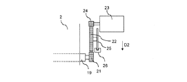
まず、図5を用いて駆動ローラ19を回転させるローラ対駆動手段について説明する。図5は、駆動ローラ19の端部の付近を示す上面図である。図5に示すように、駆動ローラ19の端部にはローラギア21が設けられている。ローラギア21は、画像形成装置1に設けられたローラ入力ギア22と噛み合っている。   First, the roller pair driving means for rotating the driving roller 19 will be described with reference to FIG. FIG. 5 is a top view showing the vicinity of the end of the drive roller 19. As shown in FIG. 5, a roller gear 21 is provided at the end of the driving roller 19. The roller gear 21 meshes with a roller input gear 22 provided in the image forming apparatus 1.

ローラ入力ギア22は、ローラモータ23の駆動軸に設けられたモータギア24とも噛み合っている。したがって、ローラモータ23の駆動軸が回転駆動することによって、駆動ローラ19が、駆動ローラ19の軸周りに回転させられる。駆動ローラ19が回転することによってシート材2が基準方向D2へ向かって移動する。   The roller input gear 22 is also meshed with a motor gear 24 provided on the drive shaft of the roller motor 23. Therefore, the driving roller 19 is rotated around the axis of the driving roller 19 by rotating the driving shaft of the roller motor 23. As the driving roller 19 rotates, the sheet material 2 moves toward the reference direction D2.

ローラ入力ギア22にはエンコーダフィルム25が設けられており、画像形成装置1に設けられたエンコーダセンサ26によってローラ入力ギア22の回転数が検出される。ローラ入力ギア22、モータギア24およびローラギア21のギア比と、ローラ入力ギア22の回転数とから、ロールモータ14の駆動軸や駆動ローラ19の回転数が算出される。   The roller input gear 22 is provided with an encoder film 25, and the rotation speed of the roller input gear 22 is detected by an encoder sensor 26 provided in the image forming apparatus 1. From the gear ratio of the roller input gear 22, the motor gear 24 and the roller gear 21 and the rotation speed of the roller input gear 22, the rotation speed of the drive shaft of the roll motor 14 and the drive roller 19 is calculated.

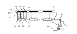
続いて、図6および図7を用いて、ローラ対18の挟圧力を変える挟圧力変更手段について説明する。図6および図7は、駆動ローラ19、ピンチローラ20および挟圧力変更手段の上面図および側面図である。   Subsequently, the clamping pressure changing means for changing the clamping pressure of the roller pair 18 will be described with reference to FIGS. 6 and 7. 6 and 7 are a top view and a side view of the drive roller 19, the pinch roller 20, and the clamping pressure changing means.

図6に示すように、ピンチローラ20は、駆動ローラ19の軸方向に沿って複数配列されている。ここでは、複数のピンチローラ20のうちの3つについて詳述する。なお、挟圧力変更手段についての説明では、3つのピンチローラ20をそれぞれ区別するために、ピンチローラ20a,20b,20cとする。   As shown in FIG. 6, a plurality of pinch rollers 20 are arranged along the axial direction of the drive roller 19. Here, three of the plurality of pinch rollers 20 will be described in detail. In the description of the clamping pressure changing means, the pinch rollers 20a, 20b, and 20c are used to distinguish the three pinch rollers 20 from each other.

ピンチローラ20a,20b,20cは、ピンチローラアーム27a,27b,27cにそれぞれ回転自在に保持されている。したがって、駆動ローラ19を挟持しているピンチローラアーム27a,27b,27cは、駆動ローラ19の回転やローラ対18に挟持されたシート材2の移動に追従して回転する。   The pinch rollers 20a, 20b, and 20c are rotatably held by the pinch roller arms 27a, 27b, and 27c, respectively. Therefore, the pinch roller arms 27a, 27b, and 27c sandwiching the drive roller 19 rotate following the rotation of the drive roller 19 and the movement of the sheet material 2 sandwiched by the roller pair 18.

また、ピンチローラ20a,20b,20cには、例えばEPDMといった、グリップ力の比較的強いゴムが用いられる。したがって、ピンチローラ20a,20b,20cと駆動ローラ19との間に挟持されたシート材2が移動する際に、シート材2上ですべることなくピンチローラ20a,20b,20cは回転することができる。   For the pinch rollers 20a, 20b, and 20c, rubber having a relatively strong grip, such as EPDM, is used. Therefore, when the sheet material 2 sandwiched between the pinch rollers 20a, 20b, and 20c and the drive roller 19 moves, the pinch rollers 20a, 20b, and 20c can rotate without sliding on the sheet material 2. .

ピンチローラアーム27a,27b,27cは、それぞれ独立して揺動可能にアーム軸28に保持されている。ピンチローラアーム27a,27b,27cには、ピンチローラ20a,20b,20cが駆動ローラ19を挟圧する方向に、付勢バネ29a,29b,29cを用いて力が加えられている。   The pinch roller arms 27a, 27b, and 27c are held on the arm shaft 28 so as to be independently swingable. A force is applied to the pinch roller arms 27a, 27b, and 27c using biasing springs 29a, 29b, and 29c in a direction in which the pinch rollers 20a, 20b, and 20c clamp the drive roller 19.

アーム軸28は、画像形成装置1内のメインステイ(不図示)に取り付けられている。したがって、ピンチローラ20a,20b,20cやピンチローラアーム27a,27b,27cに力が加えられてもアーム軸28は移動しない。   The arm shaft 28 is attached to a main stay (not shown) in the image forming apparatus 1. Therefore, even if force is applied to the pinch rollers 20a, 20b, 20c and the pinch roller arms 27a, 27b, 27c, the arm shaft 28 does not move.

また、挟圧力変更手段は、ピンチローラアーム27a,27b,27cをアーム軸28の軸周りに回転させてピンチローラ20a,20b,20cによる駆動ローラ19への挟圧力を変更する挟圧力変更カム30を備えている。挟圧力変更カム30は、ビス(不図示)を用いて挟圧力変更軸31に固定されている。   Further, the clamping pressure changing means rotates the pinch roller arms 27a, 27b, 27c around the axis of the arm shaft 28 to change the clamping pressure applied to the drive roller 19 by the pinch rollers 20a, 20b, 20c. It has. The clamping pressure change cam 30 is fixed to the clamping pressure change shaft 31 using screws (not shown).

挟圧力変更軸31の端部には挟圧力変更ギア32が設けられている。挟圧力変更ギア32は、クラッチギア33と噛みあっており、クラッチギア33はギアトレイン34と噛みあっている。さらにギアトレイン34は、挟圧力変更モータ35の駆動軸に設けられたモータギア36と噛み合っており、挟圧力変更モータ35の駆動軸が回転駆動することによって、挟圧力変更カム30が、挟圧力変更軸31の軸周りに回転させられる。   A clamping pressure change gear 32 is provided at the end of the clamping pressure change shaft 31. The clamping pressure change gear 32 is engaged with the clutch gear 33, and the clutch gear 33 is engaged with the gear train 34. Further, the gear train 34 meshes with a motor gear 36 provided on the drive shaft of the clamping pressure change motor 35, and when the drive shaft of the clamping pressure change motor 35 rotates, the clamping pressure change cam 30 changes the clamping pressure. It is rotated around the axis of the axis 31.

クラッチギア33は、電磁力により挟圧力変更ギア32との噛み合いを解除できるようになっている。所望のタイミングで電磁力をクラッチギアに加えることによって、挟圧力変更モータ35の駆動力が挟圧力変更軸31へ伝わらなくなり、挟圧力変更カム30の回転を所望のタイミングで停止する。   The clutch gear 33 can be disengaged from the clamping pressure change gear 32 by electromagnetic force. By applying electromagnetic force to the clutch gear at a desired timing, the driving force of the clamping pressure change motor 35 is not transmitted to the clamping pressure change shaft 31, and the rotation of the clamping pressure change cam 30 is stopped at the desired timing.

挟圧力変更カム30は、回転させるピンチローラアーム27a,27b,27cを、挟圧力変更カム30の回転角によって変えられるように形成されている。   The pinching pressure change cam 30 is formed so that the pinch roller arms 27 a, 27 b, 27 c to be rotated can be changed according to the rotation angle of the pinching pressure change cam 30.

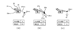
例えば、図7(a)は、ピンチローラ20a,20b,20cの全てが駆動ローラ19を押圧している状態である。この状態を基準状態とし、基準状態における挟圧力変更カム30の回転角(以下、カム角度という)を0度とする。また、基準状態における、ピンチローラ20a,20b,20cおよび駆動ローラ19による挟圧力を第2挟圧力P2とする。   For example, FIG. 7A shows a state in which all of the pinch rollers 20a, 20b, and 20c press the drive roller 19. This state is set as a reference state, and the rotation angle (hereinafter referred to as cam angle) of the clamping pressure change cam 30 in the reference state is set to 0 degree. Further, the clamping pressure by the pinch rollers 20a, 20b, 20c and the driving roller 19 in the reference state is set as a second clamping pressure P2.

図7(b)は、カム角度がθ1度(0<θ1)の状態を示す図である。この状態では、挟圧力変更カム30により、基準状態からピンチローラアーム27aのみが回転させられてピンチローラ20aによる駆動ローラ19への押圧が解除されている。したがって、この状態における第1挟圧力P1は、基準状態における第2挟圧力P2よりも小さくなっている。なお、ピンチローラ20b,20cは駆動ローラ19を押圧しているため、第1挟圧力P1は0よりも大きい値である。   FIG. 7B is a diagram illustrating a state where the cam angle is θ1 degrees (0 <θ1). In this state, the pinching pressure changing cam 30 rotates only the pinch roller arm 27a from the reference state, and the pressing of the drive roller 19 by the pinch roller 20a is released. Therefore, the first clamping pressure P1 in this state is smaller than the second clamping pressure P2 in the reference state. In addition, since the pinch rollers 20b and 20c press the driving roller 19, the first clamping pressure P1 is a value larger than zero.

図7(c)は、カム角度がθ2度(θ1<θ2)の状態を示す図である。この状態では、挟圧力変更カム30により、基準状態からピンチローラアーム27a,27b、27cの全てが回転させられている。したがって、ピンチローラ20a,20b,20cの全てによる駆動ローラ19への押圧が解除され、挟圧力は0になっている。   FIG. 7C is a diagram illustrating a state where the cam angle is θ2 degrees (θ1 <θ2). In this state, the pinch roller arms 27a, 27b, and 27c are all rotated from the reference state by the clamping pressure change cam 30. Therefore, the pressure on the drive roller 19 by all of the pinch rollers 20a, 20b, and 20c is released, and the pinching pressure is zero.

このように、挟圧力変更カム30を回転させることによって、ピンチローラ20および駆動ローラ19による挟圧力を変えることができる。   Thus, the pinching pressure by the pinch roller 20 and the drive roller 19 can be changed by rotating the pinching pressure changing cam 30.

なお、画像形成装置1がシート材2へ画像を形成する際には、カム角度は0度(第2挟圧力P2)またはθ1度(第1挟圧力P1)に設定される。ユーザーがシート材2を画像形成装置1から取り外す際に、カム角度はθ2度(挟圧力0)に設定される。   When the image forming apparatus 1 forms an image on the sheet material 2, the cam angle is set to 0 degree (second clamping pressure P2) or θ1 degree (first clamping pressure P1). When the user removes the sheet material 2 from the image forming apparatus 1, the cam angle is set to θ2 degrees (clamping pressure 0).

次に、図1,2を参照して、画像形成装置1の動作について説明する。   Next, the operation of the image forming apparatus 1 will be described with reference to FIGS.

まず、ユーザーは画像形成装置1にロール体6を保持させ、ロール体6からシート材2を引き出す。さらに、ユーザーは、画像形成装置1内に設けられた外ガイド37および内ガイド38により形成される搬送路を経由して、ローラ対18までシート材2を搬送し、ローラ対18の間にシート材2を差し込む。   First, the user holds the roll body 6 in the image forming apparatus 1 and pulls out the sheet material 2 from the roll body 6. Further, the user conveys the sheet material 2 to the roller pair 18 via a conveyance path formed by the outer guide 37 and the inner guide 38 provided in the image forming apparatus 1, and the sheet is interposed between the roller pair 18. Insert material 2.

ロール体6からローラ対18までのシート材2の経路の途中には、シート材2の有無を検出するシート材検出手段(不図示)が設けられている。ユーザーがシート材2をローラ対18へ搬送する際に、シート材検出手段がシート材2を検出する。   In the middle of the path of the sheet material 2 from the roll body 6 to the roller pair 18, sheet material detection means (not shown) for detecting the presence or absence of the sheet material 2 is provided. When the user conveys the sheet material 2 to the roller pair 18, the sheet material detection unit detects the sheet material 2.

駆動ローラ19は、シート材検出手段がシート材2を検出することによって回転駆動を開始するように制御されている。したがって、シート材2をローラ対18の間に差し込む際には駆動ローラ19が回転しており、ユーザーは容易にシート材2をローラ対18の間に差し込むことができる。   The drive roller 19 is controlled to start rotational driving when the sheet material detecting means detects the sheet material 2. Accordingly, when the sheet material 2 is inserted between the roller pair 18, the driving roller 19 is rotated, and the user can easily insert the sheet material 2 between the roller pair 18.

ローラ対18により挟持されたシート材2は、駆動ローラ19の回転によって、記録ヘッド3と対向する位置に配設されたプラテン39まで搬送される。プラテン39まで搬送されたシート材2に、記録ヘッド3により画像が形成される。   The sheet material 2 sandwiched between the roller pair 18 is conveyed to a platen 39 disposed at a position facing the recording head 3 by the rotation of the driving roller 19. An image is formed by the recording head 3 on the sheet material 2 conveyed to the platen 39.

その後、シート材2はローラ対18によってシート材カッター40まで搬送され、シート材カッター40によって裁断される。裁断されたシート材2は排紙カバー41上を滑り、不図示の排紙バスケットに収納される。   Thereafter, the sheet material 2 is conveyed to the sheet material cutter 40 by the roller pair 18 and is cut by the sheet material cutter 40. The cut sheet material 2 slides on the paper discharge cover 41 and is stored in a paper discharge basket (not shown).

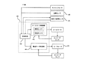
スプールユニット7やローラ対18の動作を制御する制御部について、図8を用いて詳述する。図8は、画像形成装置1(図1)の制御ブロック図である。   A control unit for controlling the operation of the spool unit 7 and the roller pair 18 will be described in detail with reference to FIG. FIG. 8 is a control block diagram of the image forming apparatus 1 (FIG. 1).

画像形成装置1に設けられた制御部42は、不図示のCPU、ROM、RAM、モータドライバ等の部品を備えており、ロールモータ14(図4)やローラモータ23(図5)へ指令を与えてロールモータ14やローラモータ23の駆動を制御する。制御部42には、主制御部43、搬送モータ制御部44およびロールモータ制御部45が含まれている。   The control unit 42 provided in the image forming apparatus 1 includes components such as a CPU, a ROM, a RAM, and a motor driver (not shown), and commands the roll motor 14 (FIG. 4) and the roller motor 23 (FIG. 5). To control the driving of the roll motor 14 and the roller motor 23. The control unit 42 includes a main control unit 43, a conveyance motor control unit 44, and a roll motor control unit 45.

主制御部43は、キャリッジ4(図1)を移動させるキャリッジモータ46や挟圧力変更モータ35から信号を受け取り、キャリッジ4や記録ヘッド3(図1)の動作に応じて搬送モータ制御部44やロールモータ制御部45へ指令を与える。   The main control unit 43 receives signals from the carriage motor 46 that moves the carriage 4 (FIG. 1) and the clamping pressure change motor 35, and according to the operation of the carriage 4 and the recording head 3 (FIG. 1) A command is given to the roll motor control unit 45.

搬送モータ制御部44は、主制御部43から受けた指令に基づいて、ローラモータ23に指令を与えてローラモータ23を駆動させる。また、搬送モータ制御部44は、エンコーダセンサ26により検出されたローラモータ23の駆動軸の回転数の信号を受け取り、実際のローラモータ23の駆動軸の回転数を観察しながら該駆動軸の回転数を制御するフィードバック制御を行う。   The transport motor control unit 44 drives the roller motor 23 by giving a command to the roller motor 23 based on the command received from the main control unit 43. Further, the conveyance motor control unit 44 receives a signal indicating the rotational speed of the drive shaft of the roller motor 23 detected by the encoder sensor 26, and rotates the drive shaft while observing the actual rotational speed of the drive shaft of the roller motor 23. Perform feedback control to control the number.

ロールモータ制御部45は、主制御部43から受けた指令に基づいて、ロールモータ14に指令を与えてロールモータ14を駆動させる。また、ロールモータ制御部45は、エンコーダセンサ17により検出されたロールモータ14の駆動軸の回転数の信号を受け取り、実際のロールモータ14の駆動軸の回転数を観察しながら該駆動軸の回転数を制御するフィードバック制御を行う。   The roll motor control unit 45 gives a command to the roll motor 14 based on the command received from the main control unit 43 to drive the roll motor 14. Further, the roll motor control unit 45 receives the rotation speed signal of the roll motor 14 detected by the encoder sensor 17 and rotates the drive shaft while observing the actual rotation speed of the roll motor 14. Perform feedback control to control the number.

ロールモータ14の駆動によって生じるシート材2の弛みやテンションについて、図8,9を用いて詳述する。図9は、シート材2に生じる弛みやテンションを説明するための図である。   The looseness and tension of the sheet material 2 generated by driving the roll motor 14 will be described in detail with reference to FIGS. FIG. 9 is a diagram for explaining slack and tension generated in the sheet material 2.

図9に示すように、シート材2がぴんと張られている位置(図9に実線で示されている位置)をシート材2の基準位置とし、シート材2の、基準位置から最も離れている部分と、基準位置との間の距離の絶対値をシート材2の弛み量Spapとして表す。また、シート材2に生じるテンションTpap(バックテンションとも呼ばれる)は、駆動ローラ19からロール体6へ向かう方向を正値とする。   As shown in FIG. 9, the position where the sheet material 2 is tensioned (the position indicated by the solid line in FIG. 9) is the reference position of the sheet material 2, and is the farthest from the reference position of the sheet material 2. The absolute value of the distance between the portion and the reference position is expressed as a slack amount Spap of the sheet material 2. Further, the tension Tpap (also referred to as back tension) generated in the sheet material 2 is a positive value in the direction from the driving roller 19 to the roll body 6.

図8,9に示すように、搬送モータ制御部44がローラモータ23の駆動軸を回転させることにより、駆動ローラ19は、ローラモータ23の駆動軸の回転速度に応じた周速度Vlf(駆動ローラ19の外周における速度)で回転する。また、ロールモータ制御部45がロールモータ14の駆動軸を回転させることにより、ロール体6は、ロールモータ14の駆動軸の回転速度に応じた周速度Vroll(ロール体6の外周における速度)で回転する。   As shown in FIGS. 8 and 9, when the conveyance motor control unit 44 rotates the drive shaft of the roller motor 23, the drive roller 19 has a peripheral speed Vlf (drive roller) corresponding to the rotation speed of the drive shaft of the roller motor 23. 19). Further, when the roll motor control unit 45 rotates the drive shaft of the roll motor 14, the roll body 6 has a peripheral speed Vroll (speed on the outer periphery of the roll body 6) according to the rotational speed of the drive shaft of the roll motor 14. Rotate.

シート材2の移動速度Vpapは、シート材2が駆動ローラ19上で滑っていない場合には駆動ローラ19の周速度Vlfと等しくなる。また、シート材2がぴんと張られている場合には、シート材2の移動速度Vpapは、ロール体6の周速度Vrollと等しくなる。   The moving speed Vpap of the sheet material 2 is equal to the peripheral speed Vlf of the driving roller 19 when the sheet material 2 is not slipping on the driving roller 19. Further, when the sheet material 2 is tightly stretched, the moving speed Vpap of the sheet material 2 is equal to the peripheral speed Vroll of the roll body 6.

なお、駆動ローラ19およびロール体6の周速度Vlf,Vroll、およびシート材2の移動速度Vpapについては、シート材2がロール体6から駆動ローラ19へ向かう方向を正の値とする。また、駆動ローラ19およびロール体6の周速度Vlf,Vrollが正の値となる駆動ローラ19およびロール体6の回転を順回転とし、順回転とは反対方向の回転を逆回転とする。   Regarding the peripheral speeds Vlf and Vroll of the drive roller 19 and the roll body 6 and the moving speed Vpap of the sheet material 2, the direction from the roll body 6 toward the drive roller 19 is a positive value. Further, the rotation of the driving roller 19 and the roll body 6 at which the peripheral speeds Vlf and Vroll of the driving roller 19 and the roll body 6 are positive values is defined as forward rotation, and the rotation in the direction opposite to the forward rotation is defined as reverse rotation.

ロールモータ14によりロール体6を順回転させることにより、シート材2はロール体6から駆動ローラ19へ向かって送り出される。   By rotating the roll body 6 forward by the roll motor 14, the sheet material 2 is sent out from the roll body 6 toward the drive roller 19.

駆動ローラ19が停止している場合やロール体6の週速度Vrollが駆動ローラ19の周速度Vlfよりも大きい場合には、ロール体6から送り出されたシート材2はロール体6と駆動ローラ19との間に滞留する。したがって、シート材2の弛み量Spapが増大する。この場合には、シート材2が弛んでいるためシート材2にはテンションTpapが発生しない。   When the driving roller 19 is stopped or when the weekly speed Vroll of the roll body 6 is higher than the peripheral speed Vlf of the driving roller 19, the sheet material 2 fed from the roll body 6 is transferred to the roll body 6 and the driving roller 19. Stay between. Accordingly, the slack amount Spap of the sheet material 2 increases. In this case, since the sheet material 2 is slack, no tension Tpap is generated in the sheet material 2.

ロール体6の週速度Vrollが駆動ローラ19の周速度Vlfよりも小さい場合には、ロール体6から送り出されるシート材2の送出量よりも、駆動ローラ19により搬出されるシート材2の搬出量の方が大きくなるため、シート材2の弛み量Spapは減少する。シート材2の弛み量Spapが減少し続けて0になった後は、シート材2がぴんと張られてシート材2にテンションTpapが上昇する。   When the weekly speed Vroll of the roll body 6 is smaller than the peripheral speed Vlf of the drive roller 19, the unloading amount of the sheet material 2 unloaded by the drive roller 19 is larger than the unloading amount of the sheet material 2 unloaded from the roll body 6. Therefore, the slack amount Spap of the sheet material 2 decreases. After the slack amount Spap of the sheet material 2 continues to decrease and becomes zero, the sheet material 2 is tightly tensioned and the tension Tpap increases on the sheet material 2.

シート材2がぴんと張られた後もロール体6が駆動ローラ19の周速度Vlfよりも小さい周速度Vrollで順回転を継続する場合には、シート材2は駆動ローラ19上で滑る。ロール体6から繰り出されるシート材2の送出量は、ロール体6の周速度Vrollを超えないからである。   When the roll body 6 continues to rotate forward at a peripheral speed Vroll smaller than the peripheral speed Vlf of the driving roller 19 even after the sheet material 2 is tightly stretched, the sheet material 2 slides on the driving roller 19. This is because the amount of the sheet material 2 fed out from the roll body 6 does not exceed the peripheral speed Vroll of the roll body 6.

また、ロールモータ14によりロール体6を逆回転させることにより、ロール体6から引き出されたシート材2はロール体6に再び巻き取られる。   Further, by rotating the roll body 6 in the reverse direction by the roll motor 14, the sheet material 2 drawn from the roll body 6 is taken up around the roll body 6 again.

このように駆動ローラ19およびロール体6の周速度Vlf,Vrollを制御することによって、シート材2を搬送しながらシート材2の弛み量SpapおよびテンションTpapを増減させることができる。   By controlling the peripheral speeds Vlf and Vroll of the drive roller 19 and the roll body 6 in this way, the slack amount Spap and the tension Tpap of the sheet material 2 can be increased or decreased while the sheet material 2 is conveyed.

ここで、画像形成装置1の、シート材2の搬送モードについて図8ないし11を用いて説明する。本発明では、シート材2を弛ませた状態でシート材2を搬送する第1搬送モード、またはシート材2をぴんと張った状態でシート材2を搬送する第2搬送モードの2つの搬送モードが制御部42に組み込まれている。搬送モードは、制御部42内に設けられた搬送モード選択手段によって選択される。   Here, the conveyance mode of the sheet material 2 of the image forming apparatus 1 will be described with reference to FIGS. In the present invention, there are two conveyance modes: a first conveyance mode in which the sheet material 2 is conveyed while the sheet material 2 is slackened, or a second conveyance mode in which the sheet material 2 is conveyed while the sheet material 2 is tightly tensioned. It is incorporated in the control unit 42. The transport mode is selected by a transport mode selection unit provided in the control unit 42.

図10の上段、中段および下段のグラフは、第1搬送モードにおける、駆動ローラ19の周速度Vlf、ロール体6の周速度Vroll、およびシート材2の弛み量Spapの時系列変化を表したものである。図11の上段、中段および下段のグラフは、第2搬送モードにおける、駆動ローラ19の周速度Vlf、ロール体6の周速度Vroll、およびシート材2の弛み量Spapの時系列変化を表したものである。   The upper, middle, and lower graphs in FIG. 10 represent time-series changes in the peripheral speed Vlf of the driving roller 19, the peripheral speed Vroll of the roll body 6, and the slack amount Spap of the sheet material 2 in the first transport mode. It is. The upper, middle, and lower graphs in FIG. 11 represent time-series changes in the peripheral speed Vlf of the drive roller 19, the peripheral speed Vroll of the roll body 6, and the slack amount Spap of the sheet material 2 in the second transport mode. It is.

まず、第1搬送モードにおける、駆動ローラ19の周速度Vlf、ロール体6の周速度Vroll、およびシート材2の弛み量Spapの時系列変化について説明する。   First, time-series changes in the peripheral speed Vlf of the driving roller 19, the peripheral speed Vroll of the roll body 6, and the slack amount Spap of the sheet material 2 in the first transport mode will be described.

図8ないし10に示すように、時間Taまでは、駆動ローラ19およびロール体6は回転していない(すなわち、駆動ローラ19およびロール体6の周速度Vlf,vrollは0である)。また、シート材2は弛んでいない状態である。   As shown in FIGS. 8 to 10, the driving roller 19 and the roll body 6 are not rotating until the time Ta (that is, the peripheral speeds Vlf and vroll of the driving roller 19 and the roll body 6 are 0). Further, the sheet material 2 is not slackened.

時間Taのタイミングで、ロールモータ制御部45は、ロールモータ14を用いてロール体6を順回転させる。時間Tbまでは駆動ローラ19は停止しているため、シート材2の弛み量Spapは増加する。   At the timing of time Ta, the roll motor control unit 45 rotates the roll body 6 forward using the roll motor 14. Since the drive roller 19 is stopped until time Tb, the slack amount Spap of the sheet material 2 increases.

時間Tbのタイミングで、搬送モータ制御部44は、ローラモータ23を用いて駆動ローラ19を順回転させ始める。時間Tbから時間Tcまでの期間では、主制御部43は、ロール体6の周速度Vrollが駆動ローラ19の周速度Vlfよりも大きくなるようにロール体6および駆動ローラ19の回転を制御している。したがって、時間Tbから時間Tcまでの期間においても、シート材2の弛み量Spapは増加する。   At the timing of time Tb, the conveyance motor control unit 44 starts to rotate the driving roller 19 forward using the roller motor 23. During the period from time Tb to time Tc, the main control unit 43 controls the rotation of the roll body 6 and the drive roller 19 so that the peripheral speed Vroll of the roll body 6 is larger than the peripheral speed Vlf of the drive roller 19. Yes. Accordingly, the slack amount Spap of the sheet material 2 also increases during the period from time Tb to time Tc.

時間Tcから時間Tdまでの期間では、ロール体6の周速度Vrollが駆動ローラ19の周速度Vlfと同じになるように、主制御部43はロール体6および駆動ローラ19の回転を制御している。また、主制御部43は、時間Tdからロール体6および駆動ローラ19の周速度Vroll,Vlfを減速させ始め、時間Teのタイミングでロール体6および駆動ローラ19の回転を停止させる。   During the period from time Tc to time Td, the main control unit 43 controls the rotation of the roll body 6 and the drive roller 19 so that the peripheral speed Vroll of the roll body 6 is the same as the peripheral speed Vlf of the drive roller 19. Yes. Further, the main control unit 43 starts to decelerate the peripheral speeds Vroll and Vlf of the roll body 6 and the driving roller 19 from time Td, and stops the rotation of the roll body 6 and the driving roller 19 at the timing of time Te.

時間Tdから時間Teまでの期間においても、ロール体6の周速度Vrollが駆動ローラ19の周速度Vlfと同じになるように、主制御部43はロール体6および駆動ローラ19の回転を制御している。したがって、時間Tcから時間Teまでの期間では、シート材2の弛み量Spapは変化しない。時間TcからTeまでの期間におけるシート材2の弛み量Spapは、駆動ローラ19の紙送り動作に影響のない必要最低限の弛みがあればよい。   In the period from time Td to time Te, the main control unit 43 controls the rotation of the roll body 6 and the drive roller 19 so that the peripheral speed Vroll of the roll body 6 is the same as the peripheral speed Vlf of the drive roller 19. ing. Therefore, the slack amount Spap of the sheet material 2 does not change during the period from the time Tc to the time Te. The slack amount Spap of the sheet material 2 during the period from the time Tc to Te may be a minimum slack that is not necessary to affect the paper feeding operation of the drive roller 19.

時間Teのタイミングで、ロールモータ制御部45は、ロール体6を逆回転させる。時間Te以降では駆動ローラ19は停止しているため、シート材2がロール体6へ巻き取られ、シート材2の弛み量Spapが減少する。   At the timing of time Te, the roll motor control unit 45 rotates the roll body 6 in the reverse direction. Since the driving roller 19 is stopped after the time Te, the sheet material 2 is wound around the roll body 6, and the slack amount Spap of the sheet material 2 decreases.

シート材2の弛み量Spapが0になった時点、すなわちシート材2がぴんと張られた時点で、ロールモータ制御部45はロール体6の回転を停止する(時間Tf)。ロール体6の逆回転は、駆動ローラ19の回転停止(時間Te)から次のロール体6の回転開始(Ta’)までの間に完了することが望ましい。   When the slack amount Spap of the sheet material 2 becomes 0, that is, when the sheet material 2 is tightly stretched, the roll motor control unit 45 stops the rotation of the roll body 6 (time Tf). The reverse rotation of the roll body 6 is preferably completed between the rotation stop of the drive roller 19 (time Te) and the start of rotation of the next roll body 6 (Ta ′).

以上の動作は、駆動ローラ19によるシート材2の搬送が行われるたびに実施される。   The above operation is performed every time the sheet material 2 is conveyed by the driving roller 19.

第1搬送モードでは、駆動ローラ19がシート材2を搬送している期間(時間Tbから時間Teまでの期間)において、シート材2の弛みが生じている。すなわち、駆動ローラ19とロール体6との間に位置するシート材2はロール体6の巻径や重量の影響を受けなくなり、シート材2のテンションTpapは0になる。   In the first transport mode, the sheet material 2 is slack during the period in which the driving roller 19 transports the sheet material 2 (the period from time Tb to time Te). That is, the sheet material 2 positioned between the driving roller 19 and the roll body 6 is not affected by the winding diameter or weight of the roll body 6, and the tension Tpap of the sheet material 2 becomes zero.

したがって、ローラ対18(図2)によるシート材2への挟圧力が比較的小さくても駆動ローラ19上でシート材2が滑ることがない。第1搬送モードは、ローラ跡が残りやすいとともに駆動ローラ19上で滑ると擦り傷がつきやすいシート材を搬送する場合に好適である。   Therefore, the sheet material 2 does not slide on the driving roller 19 even if the clamping force to the sheet material 2 by the roller pair 18 (FIG. 2) is relatively small. The first transport mode is suitable for transporting a sheet material that easily retains roller marks and is easily scratched when slipped on the drive roller 19.

また、シート材2が駆動ローラ19上で滑らないため、駆動ローラ19の周速度Vlfを検出することによってシート材2の搬送量を把握することができる。   Further, since the sheet material 2 does not slip on the driving roller 19, the conveyance amount of the sheet material 2 can be grasped by detecting the peripheral speed Vlf of the driving roller 19.

なお、本実施形態に係る第1搬送モードでは、駆動ローラ19を回転させ始める前にロール体6を回転させる方法ことによってシート材2の弛みを生じさせているが、他の方法によってシート材2に弛みを生じさせてもよい。例えば、ロール体6と駆動ローラ19とを同時に回転させ始め、かつロール体6を、駆動ローラ19の回転加速度よりも大きい回転加速度で加速させるといった方法が挙げられる。   In the first transport mode according to the present embodiment, the sheet material 2 is slackened by the method of rotating the roll body 6 before the drive roller 19 starts to rotate, but the sheet material 2 is generated by other methods. The slack may be caused to occur. For example, a method of starting to rotate the roll body 6 and the driving roller 19 at the same time and accelerating the roll body 6 with a rotational acceleration larger than the rotational acceleration of the driving roller 19 can be mentioned.

続いて、第2搬送モードにおける、駆動ローラ19の周速度Vlf、ロール体6の周速度Vrollおよびシート材2の弛み量Spapの時系列変化について説明する。   Next, time-series changes in the peripheral speed Vlf of the drive roller 19, the peripheral speed Vroll of the roll body 6, and the slack amount Spap of the sheet material 2 in the second transport mode will be described.

図8,9,11に示すように、時間Taまでは、駆動ローラ19およびロール体6は回転していない(すなわち、駆動ローラ19およびロール体6の周速度Vlf,vrollは0である)。また、シート材2は弛んでいない状態である。   As shown in FIGS. 8, 9, and 11, the drive roller 19 and the roll body 6 are not rotating until the time Ta (that is, the peripheral speeds Vlf and vroll of the drive roller 19 and the roll body 6 are 0). Further, the sheet material 2 is not slackened.

時間Taのタイミングで、主制御部43は、ロールモータ14およびローラモータ23を用いてロール体6および駆動ローラ19を回転させ始める。時間Taから時間Tbまでの期間では、主制御部43は、ロール体6の周速度Vrollが駆動ローラ19の周速度Vlfよりも小さくなるようにロール体6および駆動ローラ19の回転を制御する。したがって、時間Taから時間Tbまでの期間では、シート材2がぴんと張られて、シート材2のテンションTpapが増加する。また、駆動ローラ19は、シート材2を駆動ローラ19上で滑らせながらシート材2を搬送している。   At the timing of time Ta, the main control unit 43 starts rotating the roll body 6 and the driving roller 19 using the roll motor 14 and the roller motor 23. In the period from time Ta to time Tb, the main control unit 43 controls the rotation of the roll body 6 and the drive roller 19 so that the peripheral speed Vroll of the roll body 6 is smaller than the peripheral speed Vlf of the drive roller 19. Therefore, in the period from time Ta to time Tb, the sheet material 2 is tightly tensioned, and the tension Tpap of the sheet material 2 increases. Further, the driving roller 19 conveys the sheet material 2 while sliding the sheet material 2 on the driving roller 19.

駆動ローラ19上を滑らせながらシート材2を搬送するには、ローラ対18(図2)による挟圧力を調整し、または駆動ローラ19の材質を変更してシート材2と駆動ローラ19との摩擦係数を調整すればよい。   In order to convey the sheet material 2 while sliding on the driving roller 19, the clamping force by the roller pair 18 (FIG. 2) is adjusted, or the material of the driving roller 19 is changed to change between the sheet material 2 and the driving roller 19. What is necessary is just to adjust a friction coefficient.

時間Tbのタイミングで、主制御部43は、ロール体6aの周速度Vrollが駆動ローラ19の周速度Vlfよりも大きくなるようにロール体6aおよび駆動ローラ19の回転を制御する。その結果、シート材2のテンションTpapが減少し、シート材2の弛み量Spapが増加する。   At time Tb, the main control unit 43 controls the rotation of the roll body 6a and the drive roller 19 so that the peripheral speed Vroll of the roll body 6a is larger than the peripheral speed Vlf of the drive roller 19. As a result, the tension Tpap of the sheet material 2 decreases, and the slack amount Spap of the sheet material 2 increases.

時間Tdのタイミングで、主制御部43は、ロール体6の周速度Vrollが駆動ローラ19の周速度Vlfと同じになるようにロール体6および駆動ローラ19の回転を制御する。   At the timing of time Td, the main control unit 43 controls the rotation of the roll body 6 and the drive roller 19 so that the peripheral speed Vroll of the roll body 6 is the same as the peripheral speed Vlf of the drive roller 19.

ロール体6および駆動ローラ19の周速度Vroll,Vlfが同じになる時間Tb以降の動作は第1搬送モードと同じであるため、説明は省略する。   Since the operation after the time Tb when the peripheral speeds Vroll and Vlf of the roll body 6 and the drive roller 19 are the same is the same as in the first transport mode, the description thereof is omitted.

第2搬送モードでは、時間Taから時間Tbの期間、すなわちロールモータ制御部がロールモータ14に逆トルクを発生させている期間において、シート材2の斜行状態が補正される。   In the second transport mode, the skew state of the sheet material 2 is corrected in the period from time Ta to time Tb, that is, in the period in which the roll motor control unit generates reverse torque in the roll motor 14.

図9,12を用いてシート材2の斜行状態が修正されるメカニズムについて説明する。図12(a)は、ローラ対18によりシート材2に加えられる力(以下、搬送力H)、およびロール体6によりシート材2に加えられるテンション(以下、バンクテンションB)の分布を示す図である。図12(b)は、搬送力HとバックテンションBとの差である有効搬送力Fの分布を示す図である。   A mechanism for correcting the skew state of the sheet material 2 will be described with reference to FIGS. FIG. 12A is a diagram showing the distribution of the force applied to the sheet material 2 by the roller pair 18 (hereinafter referred to as conveyance force H) and the tension applied to the sheet material 2 by the roll body 6 (hereinafter referred to as bank tension B). It is. FIG. 12B is a diagram illustrating the distribution of the effective conveyance force F that is the difference between the conveyance force H and the back tension B.

シート材2が斜行状態にあり、かつシート材2にテンションTpapが生じている状態では、シート材2の一方の端部E1はぴんと張られており、シート材2の他方の端部E2は弛んでいる。したがって、端部E2にはバックテンションBは生じておらず、端部E2から端部E1へ進むにつれてバックテンションBは大きくなっている(図12(a))。また、搬送力Hは、端部E1から端部E2まで一定の大きさで分布している。   In a state where the sheet material 2 is in a skew state and a tension Tpap is generated in the sheet material 2, one end E1 of the sheet material 2 is tightly stretched, and the other end E2 of the sheet material 2 is You are loose. Accordingly, the back tension B does not occur at the end E2, and the back tension B increases from the end E2 to the end E1 (FIG. 12A). Further, the conveying force H is distributed with a constant magnitude from the end E1 to the end E2.

シート材2へ作用する有効搬送力Fは、搬送力HとバックテンションBとの差である。したがって、有効搬送力Fは、端部E1から端部E2へ向かうにつれて大きくなる(図12(b))。   The effective conveying force F acting on the sheet material 2 is a difference between the conveying force H and the back tension B. Therefore, the effective transport force F increases from the end E1 toward the end E2 (FIG. 12B).

端部E1側は、端部E2側に比べて有効搬送力Fが小さいため、端部E2側に比べて搬送されにくくかつ駆動ローラ19上を滑りやすい。したがって、端部E2側は端部E1側よりも搬送される量が多くなる。その結果、シート材2は、基準方向D2に向かって搬送されるとともに端部E2側から端部E1側へ向かって移動し、シート材2の斜行状態が修正される。   Since the effective transport force F is smaller on the end E1 side than on the end E2 side, the end E1 side is less likely to be transported than on the end E2 side, and slips on the driving roller 19. Therefore, the end E2 side is transported more than the end E1 side. As a result, the sheet material 2 is transported in the reference direction D2 and moves from the end E2 side to the end E1 side, and the skew state of the sheet material 2 is corrected.

また、シート材2の斜行状態は、端部E1と端部E2のバックテンションBの差が大きいほど修正されやすい。したがって、シート材2の斜行状態を修正する際には、ローラ対18のより挟圧力を大きくし、シート材2の端部E1側により大きいバックテンションBを発生させることが好ましい。   In addition, the skew state of the sheet material 2 is more easily corrected as the difference in the back tension B between the end E1 and the end E2 increases. Therefore, when correcting the skew state of the sheet material 2, it is preferable to increase the pinching pressure of the roller pair 18 and generate a larger back tension B on the end E1 side of the sheet material 2.

なお、シート材2に十分な大きさのバックテンションBを発生させられない場合には、第2搬送モードでシート材2を搬送してもシート材2の斜行状態は修正されない。したがって、第2搬送モードでシート材2を搬送する場合には、所定の値(シート材2の斜行状態を修正することができる大きさのバックテンションBをシート材2に発生させる挟圧力の値をいう)以上の挟圧力でシート材2を挟持することが望ましい。   In addition, when the back tension B having a sufficiently large size cannot be generated in the sheet material 2, the skew state of the sheet material 2 is not corrected even if the sheet material 2 is conveyed in the second conveyance mode. Therefore, when the sheet material 2 is conveyed in the second conveyance mode, a predetermined value (the nipping pressure of the back tension B that can be corrected for the skew state of the sheet material 2 is generated in the sheet material 2). It is desirable to sandwich the sheet material 2 with the above clamping pressure.

本実施形態では、第1挟圧力P1は所定の挟圧力よりも小さい挟圧力であり、第2挟圧力P2は所定の値以上の挟圧力である。   In this embodiment, the 1st clamping pressure P1 is a clamping pressure smaller than a predetermined clamping pressure, and the 2nd clamping pressure P2 is a clamping pressure more than a predetermined value.

図9,11に示すように、第2搬送モードでは、駆動ローラ19を用いてシート材2を搬送する初期の期間(時間Taから時間Tbまでの期間)において、シート材2はバックテンションB(図12)を受けている。したがって、第2挟圧力P2でシート材2を狭持し、シート材2を搬送することによってシート材2の斜行状態を修正することができる。   As shown in FIGS. 9 and 11, in the second conveyance mode, in the initial period (period from time Ta to time Tb) in which the sheet material 2 is conveyed using the driving roller 19, the sheet material 2 is in the back tension B ( Figure 12). Therefore, the skew state of the sheet material 2 can be corrected by holding the sheet material 2 with the second clamping pressure P2 and conveying the sheet material 2.

シート材2を常に弛ませた状態で搬送する画像形成装置においては、シート材2の斜行状態が発生した場合、ユーザーがシート材2の斜行状態を修正しなければならなかった。具体的には、ユーザーは、画像形成装置1の動作を止め、シート材2をローラ対18(図2)から引き抜いてローラ対18に再び差し込むといった作業をしなければならない。   In the image forming apparatus that conveys the sheet material 2 while being always slackened, the user has to correct the skew state of the sheet material 2 when the skew state of the sheet material 2 occurs. Specifically, the user must stop the operation of the image forming apparatus 1, pull out the sheet material 2 from the roller pair 18 (FIG. 2), and insert it into the roller pair 18 again.

シート材2を所定の挟圧力で挟持し、第2搬送モードでシート材2を搬送することにより斜行状態が修正されるため、ユーザーは前述の作業をする必要がなくなり、ユーザーの労力の軽減を図ることができる。第2搬送モードは、斜行状態になりやすい比較的剛度の大きいシート材を搬送する場合に好適である。比較的剛度の大きいシート材では、ローラ対18上でシート材2が滑っても擦り傷は許容範囲内に収まる。   Since the skew state is corrected by holding the sheet material 2 with a predetermined holding pressure and transferring the sheet material 2 in the second transfer mode, the user does not need to perform the above-described work, and the user's labor is reduced. Can be achieved. The second conveyance mode is suitable for conveying a sheet material having a relatively high rigidity that is likely to be in a skew state. In the case of a sheet material having a relatively high rigidity, even if the sheet material 2 slides on the roller pair 18, the scratches are within an allowable range.

また、時間Taから時間Tbまでの期間では、シート材2は弛んでいないため、ロール体6から送り出されるシート材2の送出量が、駆動ローラ19により実際に搬送されるシート材2の量である。すなわち、当該期間では駆動ローラ19の周速度Vlfを検出することによってシート材2の半総量を把握することができる。時間TbからTfまでの期間では、シート材2が駆動ローラ19上で滑らないため、駆動ローラ19の周速度Vlfを検出することによってシート材2の搬送量を把握することができる。   Further, since the sheet material 2 is not slack in the period from the time Ta to the time Tb, the feeding amount of the sheet material 2 fed from the roll body 6 is the amount of the sheet material 2 actually conveyed by the driving roller 19. is there. That is, during this period, the semi-total amount of the sheet material 2 can be grasped by detecting the peripheral speed Vlf of the drive roller 19. In the period from time Tb to Tf, the sheet material 2 does not slip on the driving roller 19, and therefore the conveyance amount of the sheet material 2 can be grasped by detecting the peripheral speed Vlf of the driving roller 19.

なお、本実施形態では、ロール体6の周速度Vrollを駆動ローラ19の周速度Vlfよりも小さくすることによってシート材2にテンションTpapを生じさせているが、他の方法によってシート材2にテンションTpapを生じさせてもよい。例えば、ロール体6を回転させるタイミングを、駆動ローラ19を回転させるタイミングよりも遅くする方法が挙げられる。   In the present embodiment, the tension Tpap is generated in the sheet material 2 by making the peripheral speed Vroll of the roll body 6 smaller than the peripheral speed Vlf of the driving roller 19, but the tension is applied to the sheet material 2 by other methods. Tpap may be generated. For example, there is a method in which the timing for rotating the roll body 6 is made slower than the timing for rotating the drive roller 19.

また、時間Taから時間Tbまでの期間だけでなく、時間Taから時間Tfまでの期間においてシート材2にテンションTpapを生じさせてもよい。具体的には、時間Taから時間Tfまでの期間において、駆動ローラ19を、ロール体6の周速度Vrollよりも大きい周速度Vlfで回転させればよい。シート材2にテンションTpapを生じさせる期間を長くすることによって、斜行状態の修正がより行われやすくなる。   Further, not only the period from time Ta to time Tb but also the tension Tpap may be generated in the sheet material 2 in the period from time Ta to time Tf. Specifically, in the period from time Ta to time Tf, the drive roller 19 may be rotated at a peripheral speed Vlf that is greater than the peripheral speed Vroll of the roll body 6. By increasing the period during which the tension Tpap is generated in the sheet material 2, the skew state can be more easily corrected.

次に、本実施形態に係る画像形成装置1の、給紙から印字終了までの一連の動作について、図1,2,8,13を用いて説明する。図13は画像形成装置1の動作を示したフローチャート図である。   Next, a series of operations from the paper feeding to the end of printing of the image forming apparatus 1 according to the present embodiment will be described with reference to FIGS. FIG. 13 is a flowchart showing the operation of the image forming apparatus 1.

図1,2,8,13に示すように、ユーザーはシート材2をローラ対18間に差し込こんで、画像形成装置1にシート材2を給紙する(S101)。主制御部43は、給紙されたシート材2の種類を判定する(S102)。シート材2の種類の判定は、例えばユーザーがシート材2の種類を指定することによって行われる。   As shown in FIGS. 1, 2, 8, and 13, the user inserts the sheet material 2 between the roller pair 18 and feeds the sheet material 2 to the image forming apparatus 1 (S101). The main control unit 43 determines the type of the fed sheet material 2 (S102). The type of the sheet material 2 is determined by, for example, the user specifying the type of the sheet material 2.

次に、主制御部43は、S102におけるシート材2の種類の判定の結果に基づき、シート材2が、ローラ跡が残りやすい種類であるか否かを判断する(S103)。   Next, the main control unit 43 determines whether or not the sheet material 2 is the type in which the roller marks are likely to remain based on the determination result of the type of the sheet material 2 in S102 (S103).

ローラ跡が残りやすいシート材であるか否かの判断は、制御部42に設けられたROMやRAMといった記憶部に予め、ローラ跡が残りやすいシート材の種類を記憶させておくことにより実現することができる。S102において判定されたシート材2の種類が、予め主制御部43に記憶されているシート材の種類の中にあれば、主制御部43は、ローラ跡や擦り傷がつきやすいシート材であると判断する。   The determination as to whether or not the roller trace is likely to remain is realized by storing in advance a type of sheet material on which the roller trace is likely to remain in a storage unit such as a ROM or a RAM provided in the control unit 42. be able to. If the type of the sheet material 2 determined in S102 is among the types of sheet materials stored in advance in the main control unit 43, the main control unit 43 is a sheet material that is easily damaged by a roller mark or an abrasion. to decide.

シート材2が、ローラ跡や擦り傷がつきやすい種類であると主制御部43が判断した場合、主制御部43は挟圧力変更モータ35を駆動させてローラ対18の挟圧力を第1挟圧力P1にする(S104)。   When the main control unit 43 determines that the sheet material 2 is of a type that easily causes roller marks or scratches, the main control unit 43 drives the clamping pressure change motor 35 to change the clamping pressure of the roller pair 18 to the first clamping pressure. Set to P1 (S104).

また、主制御部43は、挟圧力の大きさに基づいて搬送モードが選択されるように表1に示すテーブルを予め記憶している。表1に示すように、ローラ対18の挟圧力が第1挟圧力P1の場合、すなわち所定の値よりも小さい場合には第1搬送モードを選択し、ローラ対18の挟圧力が第2挟圧力P2の場合、すなわち所定の値以上の場合には第2搬送モードを選択する。   In addition, the main control unit 43 stores in advance the table shown in Table 1 so that the transport mode is selected based on the magnitude of the clamping pressure. As shown in Table 1, when the clamping pressure of the roller pair 18 is the first clamping pressure P1, that is, when it is smaller than a predetermined value, the first transport mode is selected, and the clamping pressure of the roller pair 18 is the second clamping pressure. In the case of the pressure P2, that is, when it is equal to or higher than a predetermined value, the second transport mode is selected.

Figure 0005769530
したがって、主制御部43は、S104においてローラ対18の挟圧力を第1挟圧力P1にするとともに、ロールモータ制御部45に第1搬送モードを選択するように指令を送る(S105)。
Figure 0005769530
Accordingly, the main control unit 43 sets the clamping pressure of the roller pair 18 to the first clamping pressure P1 in S104, and sends a command to the roll motor control unit 45 to select the first conveyance mode (S105).

S103において、シート材2が、ローラ跡が残りやすい種類でないと主制御部43が判断した場合には、主制御部43は挟圧力変更モータ35を駆動させてローラ対18の挟圧力を第1挟圧力P1にする(S106)。また、主制御部43はロールモータ制御部45に第2搬送モードを選択するように指令を送る(S107)。   In S103, when the main control unit 43 determines that the sheet material 2 is not the type in which the roller marks are likely to remain, the main control unit 43 drives the nipping pressure changing motor 35 to change the nipping pressure of the roller pair 18 to the first. The clamping pressure P1 is set (S106). The main control unit 43 sends a command to the roll motor control unit 45 to select the second transport mode (S107).

第1搬送モード、または第2搬送モードのいずれかにロールモータ制御部45の搬送モードが選択されたあと、主制御部43はキャリッジモータ46や記録ヘッド3を駆動させてシート材2に画像を形成する(S108)。   After the transport mode of the roll motor control unit 45 is selected in either the first transport mode or the second transport mode, the main control unit 43 drives the carriage motor 46 and the recording head 3 to display an image on the sheet material 2. Form (S108).

本実施形態に係る画像形成装置1によれば、シート材2の種類に応じてローラ対18の挟圧力が変更され、シート材2にローラ跡を残すことなくシート材2を搬送することができる。   According to the image forming apparatus 1 according to the present embodiment, the clamping force of the roller pair 18 is changed according to the type of the sheet material 2, and the sheet material 2 can be conveyed without leaving a roller mark on the sheet material 2. .

また、ローラ対18の挟圧力の大きさに応じて、シート材2にテンションを生じさせて搬送させるか否かが変更される。剛度が比較的大きくローラ跡や擦り傷がつきにくいシート材2においては、シート材2を比較的強い第2挟圧力P2で挟圧してシート材2にテンションを生じさせながらシート材2を搬送するため、シート材2の斜行状態を修正することができる。ローラ跡が残りやすいシート材2においては、シート材2を常に弛ませた状態で搬送されるため、シート材2がローラ対18上で滑ることが無く、シート材2に擦り傷はつかない。   Further, whether or not the sheet material 2 is conveyed by being tensioned is changed according to the magnitude of the clamping force of the roller pair 18. In the case of the sheet material 2 having a relatively high rigidity and hardly suffering from a roller mark or an abrasion, the sheet material 2 is conveyed while being tensioned by pressing the sheet material 2 with a relatively strong second clamping pressure P2. The skew state of the sheet material 2 can be corrected. In the sheet material 2 on which the roller marks tend to remain, the sheet material 2 is always conveyed in a relaxed state, and therefore the sheet material 2 does not slide on the roller pair 18 and the sheet material 2 is not scratched.

(実施例2)
次に、本発明の第2の実施形態について、図面に基づいて詳細に説明する。
(Example 2)
Next, a second embodiment of the present invention will be described in detail based on the drawings.

図14は、本実施形態に係る画像形成装置を示す斜視図である。本実施形態に係る画像形成装置47は、キャリッジ4の、走査方向D1と交わる面に距離センサ48が設置されている。距離センサ48以外の構成は、第1の実施形態と同様の形態である。なお、第1の実施形態の構成要素と同一の構成要素については、同一の符号を用いて簡単な説明に留めることにする。   FIG. 14 is a perspective view showing the image forming apparatus according to the present embodiment. In the image forming apparatus 47 according to the present embodiment, a distance sensor 48 is installed on the surface of the carriage 4 that intersects the scanning direction D1. The configuration other than the distance sensor 48 is the same as that of the first embodiment. In addition, about the component same as the component of 1st Embodiment, it will keep only a simple description using the same code | symbol.

図15(a)は、プラテン39まで搬送されたシート材2と、記録ヘッド3との間を、走査方向D1から見た拡大側面図である。図15(a)に示すように、距離センサ48は、記録ヘッド3とプラテン39との間を通過するシート材2の画像形成面から距離センサ48までの距離Lを測定する。   FIG. 15A is an enlarged side view of the space between the sheet material 2 conveyed to the platen 39 and the recording head 3 as viewed from the scanning direction D1. As shown in FIG. 15A, the distance sensor 48 measures a distance L from the image forming surface of the sheet material 2 passing between the recording head 3 and the platen 39 to the distance sensor 48.

距離センサ48としては、測定物に赤外光を出射する発光部と、測定物からの反射光を受光する受光素子とを有する赤外線反射型距離センサといったものが用いられる。   As the distance sensor 48, an infrared reflection type distance sensor having a light emitting unit that emits infrared light to a measurement object and a light receiving element that receives reflected light from the measurement object is used.

図15(b)は、図15(a)に示す記録ヘッド3とシート材2との間を、基準方向D2から見た拡大正面図である。図15(b)に示すように、画像形成面に当接する側のピンチローラ20は、画像形成面の全領域と当接するわけではなく、画像形成面の一部と当接するように設けられている。   FIG. 15B is an enlarged front view of the space between the recording head 3 and the sheet material 2 shown in FIG. As shown in FIG. 15B, the pinch roller 20 on the side in contact with the image forming surface is not in contact with the entire area of the image forming surface but is provided in contact with a part of the image forming surface. Yes.

したがって、ローラ対18に挟持されたシート材2の画像形成面には、ピンチローラ20が当接しなかった非当接領域W1と、ピンチローラ20が当接した当接領域W2と、が含まれている。当接領域W2はピンチローラ20の押圧力により圧迫されるため、シート材2の画像形成面には凹み部が形成されている。   Therefore, the non-contact area W1 where the pinch roller 20 is not in contact and the contact area W2 where the pinch roller 20 is in contact are included in the image forming surface of the sheet material 2 held between the roller pair 18. ing. Since the contact area W <b> 2 is pressed by the pressing force of the pinch roller 20, a recess is formed on the image forming surface of the sheet material 2.

距離センサ48は、キャリッジ4に設けられているため、キャリッジ4とともに走査方向D1に沿って移動することができる。したがって、非当接領域W1と対向する位置で画像形成面から距離センサ48までの距離を距離センサ48が測定することにより、非当接領域W1と距離センサ48との間の距離L1を測定することができる。また、当接領域W2と対向する位置で画像形成面から距離センサ48までの距離を距離センサ48が測定することにより、当接領域W2と距離センサ48との間の距離L2を測定することができる。   Since the distance sensor 48 is provided on the carriage 4, it can move along with the carriage 4 along the scanning direction D <b> 1. Therefore, the distance sensor 48 measures the distance from the image forming surface to the distance sensor 48 at a position facing the non-contact area W1, thereby measuring the distance L1 between the non-contact area W1 and the distance sensor 48. be able to. In addition, the distance sensor 48 measures the distance from the image forming surface to the distance sensor 48 at a position facing the contact area W2, whereby the distance L2 between the contact area W2 and the distance sensor 48 can be measured. it can.

距離センサ48により測定された距離L1,L2の差分を制御部42が算出することにより、ピンチローラ20の押圧によるシート材2の凹み量ΔLが得られる。距離センサ4
8や距離L1,L2の差分を算出する手段を含むものは、凹み量測定手段と呼ばれる。
When the control unit 42 calculates the difference between the distances L1 and L2 measured by the distance sensor 48, the dent amount ΔL of the sheet material 2 due to the pressing of the pinch roller 20 is obtained. Distance sensor 4
8 including a means for calculating the difference between 8 and the distances L1 and L2 is referred to as a dent amount measuring means.

本実施形態では、凹み量測定手段よって得られた凹み量ΔLの値に基づいて、画像形成
装置47に装着されたシート材2が、ローラ跡が残りやすい種類であるか否かが判断される。
In the present embodiment, based on the value of the dent amount ΔL obtained by the dent amount measuring means, it is determined whether or not the sheet material 2 mounted on the image forming apparatus 47 is a type in which roller marks are likely to remain. .

図16は、本実施形態例に係る画像形成装置47の制御ブロック図である。図16に示すように、主制御部43は、距離センサ48に、走査方向D1における少なくとも2箇所において距離Lを測定させ、距離センサ48によって測定された距離Lを受け取る。   FIG. 16 is a control block diagram of the image forming apparatus 47 according to this embodiment. As shown in FIG. 16, the main control unit 43 causes the distance sensor 48 to measure the distance L at at least two locations in the scanning direction D <b> 1 and receives the distance L measured by the distance sensor 48.

シート材2の非当接領域W1と当接領域W2は、ピンチローラ20の配置によって予め把握されている。したがって、非当接領域W1および当接領域W2における距離Lを距離センサ48が測定するように、予め主制御部43を設定しておくことが好ましい。   The non-contact area W1 and the contact area W2 of the sheet material 2 are grasped in advance by the arrangement of the pinch rollers 20. Therefore, it is preferable to set the main control unit 43 in advance so that the distance sensor 48 measures the distance L in the non-contact area W1 and the contact area W2.

主制御部43は、距離センサ48から受け取った少なくとも2つの距離Lの値から、厚さ変化量ΔLを算出する。算出された厚さ変化量ΔLに基づいて、主制御部43は挟圧力
変更モータ35を駆動させてローラ対18による挟圧力を変えるとともに、ロールモータ制御部45に指令を送り、搬送モードの切り替えを行う。
The main control unit 43 calculates the thickness change amount ΔL from the values of at least two distances L received from the distance sensor 48. Based on the calculated thickness change amount ΔL, the main control unit 43 drives the clamping pressure change motor 35 to change the clamping pressure by the roller pair 18 and sends a command to the roll motor control unit 45 to switch the conveyance mode. I do.

次に、本実施形態に係る画像形成装置47における給紙から画像形成終了までの一連の動作について、図17を用いて説明する。図17は画像形成装置47の動作を示したフローチャート図である。   Next, a series of operations from paper feeding to the end of image formation in the image forming apparatus 47 according to the present embodiment will be described with reference to FIG. FIG. 17 is a flowchart showing the operation of the image forming apparatus 47.

図17に示すように、ユーザーは、シート材2をローラ対18間に差し込んでシート材2を給紙する(S201)。シート材2が給紙されると、主制御部43は、挟圧力変更モータ35に指令を与え、ローラ対18の挟圧力を、変更可能な範囲のうちの最大の挟圧力である第2挟圧力P2に設定する(S202)。   As shown in FIG. 17, the user inserts the sheet material 2 between the roller pair 18 and feeds the sheet material 2 (S201). When the sheet material 2 is fed, the main control unit 43 gives a command to the clamping pressure changing motor 35, and the clamping pressure of the roller pair 18 is the second clamping pressure that is the maximum clamping pressure in the changeable range. The pressure is set to P2 (S202).

その後、主制御部43は、搬送モータ制御部44を介してローラモータ23を駆動させてシート材2を距離センサ48に対向する位置まで搬送させる(S203)。主制御部43はキャリッジモータを駆動させるとともに、距離センサ48にシート材2までの距離Lを測定させる(S204)。距離センサ48は、少なくとも、非当接領域W1と当接領域W2を含む2箇所以上において距離Lを測定する。   Thereafter, the main control unit 43 drives the roller motor 23 via the conveyance motor control unit 44 to convey the sheet material 2 to a position facing the distance sensor 48 (S203). The main controller 43 drives the carriage motor and causes the distance sensor 48 to measure the distance L to the sheet material 2 (S204). The distance sensor 48 measures the distance L at least at two locations including the non-contact area W1 and the contact area W2.

主制御部43は距離センサ48により測定された距離Lを受け取り、厚さ変化量ΔLを
算出し、予め主制御部43に記憶されている閾値ΔL1と厚さ変化量ΔLとの大小を比較
する(S205)。閾値ΔL1は、ローラ跡が残りやすいシート材か否かの判断の基準で
あり、厚さ変化量ΔLが閾値ΔL1よりも大きい場合には、シート材2はローラ跡が残り
やすい種類であると判断される。
The main control unit 43 receives the distance L measured by the distance sensor 48, calculates the thickness change amount ΔL, and compares the threshold value ΔL1 stored in the main control unit 43 in advance with the thickness change amount ΔL. (S205). The threshold value ΔL1 is a criterion for determining whether or not the roller material is likely to leave a roller mark. When the thickness change amount ΔL is larger than the threshold value ΔL1, the sheet material 2 is determined to be a type in which the roller mark is likely to remain. Is done.

シート材2が、ローラ跡が残りやすい種類であると主制御部43が判断した場合、主制御部43は挟圧力変更モータ35を駆動させてローラ対18の挟圧力を第1挟圧力P1にする(S206)。また、主制御部43は、ロールモータ制御部45に第1搬送モードを選択するように指令を送る(S207)。   When the main control unit 43 determines that the sheet material 2 is of a type in which roller marks are likely to remain, the main control unit 43 drives the clamping pressure changing motor 35 to change the clamping pressure of the roller pair 18 to the first clamping pressure P1. (S206). In addition, the main control unit 43 sends a command to the roll motor control unit 45 to select the first transport mode (S207).

S205において、シート材2が、ローラ跡がつきやすい種類でないと主制御部43が判断した場合には、主制御部43は、ローラ対18の挟圧力を第2挟圧力P2のまま維持し、ロールモータ制御部45に第2搬送モードを選択するように指令を送る(S208)。   In S205, when the main control unit 43 determines that the sheet material 2 is not of a type that easily causes roller marks, the main control unit 43 maintains the clamping pressure of the roller pair 18 as the second clamping pressure P2, A command is sent to the roll motor control unit 45 to select the second transport mode (S208).

第1搬送モード、または第2搬送モードのいずれかにロールモータ制御部45の搬送モードが選択されたあと、主制御部43はキャリッジモータ46や記録ヘッド3を駆動させてシート材2に画像を形成する(S209)。   After the transport mode of the roll motor control unit 45 is selected in either the first transport mode or the second transport mode, the main control unit 43 drives the carriage motor 46 and the recording head 3 to display an image on the sheet material 2. Form (S209).

本実施形態に係る画像形成装置47では、シート材2を実際にローラ対18で挟圧し、シート材2にローラ跡がついているか否かを判断する。したがって、ユーザーが誤ってシート材2の種類を入力した場合や、主制御部43に記憶されていない種類のシート材を用いる場合でも、適切にローラ対18の挟圧力を変更し、搬送モードを変更することができる。   In the image forming apparatus 47 according to the present embodiment, the sheet material 2 is actually clamped by the roller pair 18 to determine whether or not the sheet material 2 has a roller mark. Therefore, even when the user erroneously inputs the type of the sheet material 2 or when using a type of sheet material that is not stored in the main control unit 43, the holding pressure of the roller pair 18 is appropriately changed, and the conveyance mode is changed. Can be changed.

(実施例3)
次に、本発明の第2の実施形態について、図18,19に基づいて詳細に説明する。
(Example 3)
Next, a second embodiment of the present invention will be described in detail with reference to FIGS.

図18は、本実施形態に係る画像形成装置のローラ対18から基準方向D2側の部分の上面図であり、記録ヘッド3によって画像が形成されたシート材2が描かれている。なお、第1,第2の実施形態の構成要素と同一の構成要素については、同一の符号を用いて簡単な説明に留めることにする。   FIG. 18 is a top view of the portion on the reference direction D2 side from the roller pair 18 of the image forming apparatus according to the present embodiment, in which the sheet material 2 on which an image is formed by the recording head 3 is depicted. In addition, about the component same as the component of 1st, 2nd embodiment, it will keep only simple description using the same code | symbol.

図18に示すように、本実施形態に係る画像形成装置49は、記録ヘッド3よりも基準方向D2側に、色度を測定する測色器50をさらに備えている。測色器50は、走査方向D1に沿って延びるレール51に、往復移動可能に設けられており、シート材2に形成された画像の全領域の色度を測定できるようになっている。   As shown in FIG. 18, the image forming apparatus 49 according to the present embodiment further includes a colorimeter 50 that measures chromaticity on the reference direction D2 side with respect to the recording head 3. The colorimeter 50 is provided on the rail 51 extending along the scanning direction D1 so as to be reciprocally movable, and can measure the chromaticity of the entire area of the image formed on the sheet material 2.

測色器50は、シート材2に形成された画像の色度を測定し、当該画像が所望の色で形成されているか否かを確認するために用いられる。画像の色度を測定する際の画像形成装置49の動作について説明する。ここでは、シート材2が、比較的剛性が強く、ローラ跡のつきにくい種類である場合について説明する。   The colorimeter 50 is used to measure the chromaticity of an image formed on the sheet material 2 and confirm whether or not the image is formed with a desired color. The operation of the image forming apparatus 49 when measuring the chromaticity of an image will be described. Here, a case where the sheet material 2 is of a type having relatively high rigidity and hardly having a roller mark will be described.

まず、図18(a)に示すように、画像形成装置49は、シート材2を基準方向D2へ向かって搬送させながら、記録ヘッド3を用いてシート材2へ画像を形成する。このとき、シート材2上には、所望の画像F1と色度検出用のカラーパッチF2が、走査方向D1に隣り合って形成される。シート材2はローラ跡のつきにくい種類であるため、ローラ対18は第2挟圧力P2でシート材2を挟持し、画像形成装置49は第2搬送モードでシート材2を搬送する。   First, as shown in FIG. 18A, the image forming apparatus 49 forms an image on the sheet material 2 using the recording head 3 while conveying the sheet material 2 in the reference direction D2. At this time, a desired image F1 and a color patch F2 for chromaticity detection are formed adjacent to each other in the scanning direction D1 on the sheet material 2. Since the sheet material 2 is of a type that hardly causes a roller mark, the roller pair 18 clamps the sheet material 2 with the second clamping pressure P2, and the image forming apparatus 49 conveys the sheet material 2 in the second conveyance mode.

その後、所望の画像F1とカラーパッチF2をシート材2に定着させるために、画像形成装置49は所定の時間待機する。画像F1およびカラーパッチF2がシート材2に定着したところで、測色器50を用いてカラーパッチF2の色度を測定し、記録ヘッド3が所望の色で画像F1を形成しているか否かを確認する。   Thereafter, the image forming apparatus 49 waits for a predetermined time in order to fix the desired image F1 and the color patch F2 to the sheet material 2. When the image F1 and the color patch F2 are fixed to the sheet material 2, the chromaticity of the color patch F2 is measured using the colorimeter 50, and it is determined whether or not the recording head 3 forms the image F1 with a desired color. Check.

画像F1やカラーパッチF2が形成されている領域の、基準方向D2における長さが、記録ヘッド3と測色器50との間の距離よりも大きい場合には、画像形成装置49は、ローラ対18を用いてシート材2を基準方向D2とは反対の方向へ搬送する。図18(b)は、図18(a)に示す状態から、シート材2を基準方向D2とは反対の方向へ搬送した場合の上面図である。   When the length in the reference direction D2 of the area where the image F1 and the color patch F2 are formed is longer than the distance between the recording head 3 and the colorimeter 50, the image forming apparatus 49 uses a roller pair. 18 is used to transport the sheet material 2 in a direction opposite to the reference direction D2. FIG. 18B is a top view when the sheet material 2 is conveyed in the direction opposite to the reference direction D2 from the state shown in FIG.

図18(c)は、図18(b)に示す状態から、シート材2を基準方向D2へ搬送したときの上面図である。図18(c)に示すように、ローラ対18の挟圧力によっては、シート材2の画像F1やカラーパッチF2が形成された領域をピンチローラ20が挟圧すると、当該領域にローラ跡F3が残ることがある。カラーパッチF2が形成された領域にローラ跡F3が残ると、カラーパッチF2の色度が変化し、カラーパッチF2の色度を測定しても記録ヘッド3が所望の色度で画像F1を形成しているか否かを確認できなくなる。   FIG. 18C is a top view when the sheet material 2 is conveyed in the reference direction D2 from the state shown in FIG. As shown in FIG. 18C, depending on the clamping pressure of the roller pair 18, when the pinch roller 20 clamps the area where the image F1 or the color patch F2 of the sheet material 2 is formed, the roller trace F3 is generated in the area. May remain. When the roller trace F3 remains in the area where the color patch F2 is formed, the chromaticity of the color patch F2 changes, and the recording head 3 forms the image F1 with the desired chromaticity even if the chromaticity of the color patch F2 is measured. It becomes impossible to confirm whether or not.

本実施形態に係る画像形成装置49では、画像の色度を測定する際には、ローラ対18は、第2挟圧力P2よりも弱い第1挟圧力P1でシート材2を挟持する。すなわち、カラーパッチF2が形成されたシート材2を基準方向D2とは反対方向に搬送し、かつ基準方向D2とは反対方向へ搬送されたシート材2を再び基準方向D2へ搬送しても、カラーパッチF2にローラ跡F3はつかない。したがって、カラーパッチF2の色度を測定して記録ヘッド3が所望の色で画像F1を形成しているか否かを確認することができる。   In the image forming apparatus 49 according to the present embodiment, when measuring the chromaticity of the image, the roller pair 18 holds the sheet material 2 with the first holding pressure P1 that is weaker than the second holding pressure P2. That is, even if the sheet material 2 on which the color patch F2 is formed is conveyed in the direction opposite to the reference direction D2, and the sheet material 2 conveyed in the direction opposite to the reference direction D2 is conveyed again in the reference direction D2, The roller patch F3 is not attached to the color patch F2. Accordingly, the chromaticity of the color patch F2 can be measured to confirm whether or not the recording head 3 forms the image F1 with a desired color.

また、画像の色度を測定する際には、画像形成装置49は、第1搬送モードでシート材2を搬送する。したがって、基準方向D2とは反対方向へ搬送されたシート材2を再び基準方向D2へ搬送する際にはシート材2にテンションが発生しない。したがって、シート材2を駆動ローラ19で滑らせることなくシート材2を搬送することができる。   Further, when measuring the chromaticity of the image, the image forming apparatus 49 conveys the sheet material 2 in the first conveyance mode. Therefore, when the sheet material 2 conveyed in the direction opposite to the reference direction D2 is conveyed again in the reference direction D2, no tension is generated in the sheet material 2. Therefore, the sheet material 2 can be conveyed without sliding the sheet material 2 with the driving roller 19.

次に、本実施形態に係る画像形成装置49における給紙から画像形成終了までの一連の動作について、図19を用いて説明する。図19は画像形成装置49の動作を示したフローチャート図である。   Next, a series of operations from paper feeding to the end of image formation in the image forming apparatus 49 according to the present embodiment will be described with reference to FIG. FIG. 19 is a flowchart showing the operation of the image forming apparatus 49.

図19に示すように、ユーザーは、ローラ跡がつきにくいシート材2をローラ対18間に差し込んでシート材2を給紙する(S301)。シート材2が給紙されると、主制御部43は、挟圧力変更モータ35に指令を与えて、ローラ対18の挟圧力を第2挟圧力P2に設定する(S302)。さらに主制御部43は、ロールモータ制御部45に第2搬送モードを選択するように指令を送る(S303)。   As shown in FIG. 19, the user feeds the sheet material 2 by inserting the sheet material 2, on which the roller marks are difficult to be attached, between the roller pair 18 (S <b> 301). When the sheet material 2 is fed, the main control unit 43 gives a command to the clamping pressure changing motor 35 to set the clamping pressure of the roller pair 18 to the second clamping pressure P2 (S302). Further, the main control unit 43 sends a command to the roll motor control unit 45 to select the second transport mode (S303).

その後、主制御部43は、キャリッジモータ46や記録ヘッド3を駆動させてシート材2に所望の画像F1やカラーパッチF2を形成する(S304)。   Thereafter, the main control unit 43 drives the carriage motor 46 and the recording head 3 to form a desired image F1 and color patch F2 on the sheet material 2 (S304).

画像F16やカラーパッチF2の形成が完了したところで(S305)、主制御部43は、測色を行うか否か判断する(S306)。測色を行うか否かは、ユーザーによる画像形成装置49の操作や、予め主制御部43に記憶された動作手順によって判断される。   When the formation of the image F16 and the color patch F2 is completed (S305), the main control unit 43 determines whether or not to perform color measurement (S306). Whether or not to perform color measurement is determined by an operation of the image forming apparatus 49 by the user or an operation procedure stored in the main control unit 43 in advance.

主制御部43が測色を行うと判断した場合、主制御部43は、挟圧力変更モータ35に指令を与えてローラ対18の挟圧力を、変更可能な範囲のうちの最小の挟圧力である第1挟圧力P1に変更する(S307)。また、主制御部43は、ロールモータ制御部45に第1搬送モードを選択するように指令を送る(S308)。   When the main control unit 43 determines that the color measurement is to be performed, the main control unit 43 gives a command to the clamping pressure changing motor 35 so that the clamping pressure of the roller pair 18 is the smallest clamping pressure in the changeable range. The pressure is changed to a certain first clamping pressure P1 (S307). The main control unit 43 sends a command to the roll motor control unit 45 to select the first transport mode (S308).

その後、主制御部43は、シート材2を基準方向D2とは反対方向へ搬送し、再びシート材2を基準方向D2へ搬送しながら測色器50を用いてカラーパッチF2の測色を行い、記録ヘッド3が所望の色で画像F1を形成しているか否かを確認する(S309)。   Thereafter, the main control unit 43 performs colorimetry of the color patch F2 using the colorimeter 50 while conveying the sheet material 2 in the direction opposite to the reference direction D2, and again conveying the sheet material 2 in the reference direction D2. Then, it is confirmed whether or not the recording head 3 forms the image F1 with a desired color (S309).

測色が完了したところ、またはS306において主制御部43が測色を行わないと判断したところで、主制御部43は、シート材2への画像の形成を継続するか否かの判断を行う(S310)。シート材2への画像の形成を継続する場合、主制御部43はS302から動作を再び開始する。シート材2への画像の形成を継続しない場合には、画像形成装置49の動作は終了する。   When the color measurement is completed or when the main control unit 43 determines not to perform color measurement in S306, the main control unit 43 determines whether or not to continue image formation on the sheet material 2 ( S310). When the image formation on the sheet material 2 is continued, the main control unit 43 starts the operation again from S302. When the image formation on the sheet material 2 is not continued, the operation of the image forming apparatus 49 ends.

本実施形態に係る画像形成装置49は、ローラ跡がつきにくいシート材2に画像を形成するときには、ローラ対18が第2挟圧力P2でシート材2を挟持し、かつシート材2にテンションを発生させた状態でシート材2を搬送する。したがって、シート材2の斜行状態を修正しながらシート材2を搬送し、シート材2に画像の形成をすることができる。   In the image forming apparatus 49 according to the present embodiment, when an image is formed on the sheet material 2 on which the roller marks are hard to stick, the roller pair 18 holds the sheet material 2 with the second clamping pressure P2, and tension is applied to the sheet material 2. The sheet material 2 is conveyed in the generated state. Therefore, the sheet material 2 can be conveyed while correcting the skew state of the sheet material 2, and an image can be formed on the sheet material 2.

また、測色を行う際には、ローラ対18の挟圧力が第1挟圧力P1に変更され、かつ弛んだ状態でシート材2が搬送される。したがって、画像形成装置49は、シート材2に形成された画像にローラ跡をつけることなくシート材2を搬送することができ、所望の色度で画像が形成されているか否かをより正確に確認することができる。   Further, when performing color measurement, the clamping force of the roller pair 18 is changed to the first clamping pressure P1, and the sheet material 2 is conveyed in a slack state. Therefore, the image forming apparatus 49 can convey the sheet material 2 without making a roller mark on the image formed on the sheet material 2, and more accurately determine whether the image is formed with a desired chromaticity. Can be confirmed.

本実施形態の説明では、シート材2として、比較的剛性が強くローラ跡がつきにくい種類のものを用いているが、ローラ跡がつきやすいシート材に画像を形成する場合にも適用することができる。ローラ跡のつきやすいシート材を用いる場合には、S302においてローラ対18の挟圧力を第1挟圧力P1にし、S303において第1搬送モードに設定する。   In the description of the present embodiment, the sheet material 2 is of a type that is relatively rigid and difficult to make a roller mark, but it can also be applied to the case where an image is formed on a sheet material that easily has a roller mark. it can. In the case where a sheet material with easy roller marks is used, the clamping pressure of the roller pair 18 is set to the first clamping pressure P1 in S302, and the first conveyance mode is set in S303.

また、距離センサ48を画像形成装置49に設け、距離センサ48によって、シート材2が、ローラ跡がつきにくい種類であるか否かを判断してもよい。   Further, the distance sensor 48 may be provided in the image forming apparatus 49, and the distance sensor 48 may determine whether or not the sheet material 2 is of a type that hardly causes a roller mark.

1 画像形成装置
2 シート材
3 記録ヘッド
6 ロール体
7 スプールユニット
14 ロールモータ
18 ローラ対
23 ローラモータ
35 挟圧力変更モータ
DESCRIPTION OF SYMBOLS 1 Image forming apparatus 2 Sheet material 3 Recording head 6 Roll body 7 Spool unit 14 Roll motor 18 Roller pair 23 Roller motor 35 Clamping pressure change motor

Claims (8)

記録ヘッドによって画像が形成されるシート材がロール状に巻かれたロール体を保持するともに該ロール体の軸周りに該ロール体を回転させて該ロール体からシート材を送り出す送出手段と、前記送出手段と前記記録ヘッドとの間に、シート材を挟持可能にかつ該シート材への挟圧力を変更可能に設けられたローラ対と、前記ローラ対の少なくとも一方を回転させて前記ローラ対に挟持されたシート材を前記ロール体から前記記録ヘッドへ向かって搬出させるローラ対駆動手段と、を備えた画像形成装置において、
前記ローラ対に挟持されたシート材の種類に基づいて、前記ローラ対の挟圧力の大きさを変更する挟圧力変更手段と
記挟圧力変更手段により変更された前記ローラ対の挟圧力が所定の値よりも小さい場合には前記送出手段による前記ロール体の回転によって該ロール体から送り出されるシート材の送出量を前記ローラ対駆動手段による前記ローラ対の回転によって搬出されるシート材の搬出量よりも多くする第1搬送モードを選択し、前記挟圧力変更手段により変更された前記ローラ対の挟圧力が前記所定の値以上の場合には前記送出手段によるシート材の送出量を前記ローラ対駆動手段によるシート材の搬出量よりも少なくする第2搬送モードを選択する搬送モード選択手段と、をさらに備えたことを特徴とする画像形成装置。
And sending means for rotating the said roll body together when the sheet material on which an image is formed for holding a roll body which he wound in a roll shape around the axis of the roll body feeding the sheet material from the roll body by the recording head, A roller pair provided between the feeding means and the recording head so that the sheet material can be sandwiched and the sandwiching pressure on the sheet material can be changed, and at least one of the roller pair is rotated to rotate the roller pair. In an image forming apparatus comprising: a roller pair driving unit that unloads the sheet material sandwiched between the roll body toward the recording head,
Based on the type of sheet material is sandwiched the rollers, the clamping force changing means for changing the magnitude of the clamping force of the rollers,
The roller transmission quantity of the sheet material fed by the rotation of the roll body by the delivery means when clamping pressure of the roller pair which is modified by pre bellflower pressure changing means is smaller than a predetermined value from the roll selecting a first transport mode is set to more than out of the sheet material to be conveyed by rotation of the rollers by pairs driving means, clamping pressure of the roller pair which is changed by the squeezing force changing means of the predetermined further comprising a, a transport mode selecting means for selecting the second conveyance mode is set to less than discharge amount of the sheet material the transmission amount of the sheet material by the roller pair driving means by said sending means in the case of more than the value An image forming apparatus.
前記所定の値は、前記第2搬送モードでシート材を搬送する際にシート材の斜行状態を修正することができる大きさのテンションを発生させる挟圧力であることを特徴とする、請求項1に記載の画像形成装置。   The predetermined value is a pinching pressure that generates a tension having a magnitude capable of correcting a skew state of the sheet material when the sheet material is conveyed in the second conveyance mode. The image forming apparatus according to 1. 記シート材の種類、前記ローラ対を用いて前記所定の値の挟圧力でシート材を挟持した場合に前記ローラ対の跡が画像形成面に残るシート材であるか否かの基準により分けられた種類であり、
前記挟圧力変更手段は、前記ローラ対に挟持されたシート材が前記ローラ対の跡が残るシート材である場合に前記ローラ対の挟圧力を前記所定の値よりも小さい挟圧力に変更し、前記ローラ対に挟持されたシート材が前記ローラ対の跡が残らないシート材である場合に前記ローラ対の挟圧力を前記所定の値の挟圧力に変更することを特徴とする、請求項1または2に記載の画像形成装置。
Previous types of carboxymethyl over DOO material, said pair of rollers the rollers of the marks when clamping the sheet material in clamping force of the predetermined value by using of whether the sheet material remaining on the image forming surface It is a kind divided by criteria,
The squeezing force changing means, prior Symbol the roller pair of clamping pressure roller pair pinching sheets material in case Ru sheet der the traces of the rollers remains in the predetermined small clamping pressure than the value characterized in that change, prior Symbol roller pair sandwiched sheet material to change the clamping pressure of the rollers on the sheet material der Ru if not left traces of the roller pair nipping pressure of said predetermined value The image forming apparatus according to claim 1 or 2.
前記ローラ対を用いて前記所定の値の挟圧力でシート材を挟持した場合に前記ローラ対の跡が画像形成面に残るシート材であるか否かの種類を予め記憶している記憶部をさらに有し、
ユーザーにより入力されたシート材の種類が前記記憶部に予め記憶されたシート材の種類の中にあるか否かにより実際に前記ローラ対に挟持されたシート材の種類判断されることを特徴とする、請求項3に記載の画像形成装置。
A storage unit that stores in advance a type of whether or not a mark of the roller pair is a sheet material that remains on the image forming surface when the sheet material is clamped with the predetermined value of clamping force using the roller pair; In addition,
Wherein Rukoto actually a type of the roller pair is nipped sheet material by determining whether the type of the input sheet material by the user is in the type of pre-stored sheet material in the storage unit is determined The image forming apparatus according to claim 3.
前記ローラ対のうちの、シート材の画像形成面と当接する側の一方のローラが、該画像形成面の一部のみに当接するように形成されており、
前記画像形成装置は、前記ローラ対が前記所定の値の挟圧力でシート材を挟持した場合に前記一方のローラが前記画像形成面の一部と当接することによって形成された前記画像形成面の凹み部の凹み量を測定する凹み量測定手段をさらに有し
記凹み量測定手段により測定された凹み量に基づいて、前記シート材の種類判断されることを特徴とする、請求項1ないし3のいずれか1項に記載の画像形成装置。
Of the pair of rollers, one roller on the side in contact with the image forming surface of the sheet material is formed so as to contact only a part of the image forming surface,
In the image forming apparatus, when the roller pair holds the sheet material with the holding pressure of the predetermined value, the one roller is in contact with a part of the image forming surface. A dent amount measuring means for measuring the dent amount of the dent portion ;
Based on the recessed amount measured by the previous SL dent amount measuring means, the type of sheet material is determined, characterized in Rukoto image forming apparatus according to any one of claims 1 to 3.
前記第2搬送モードは、前記ローラ対に挟持されたシート材を搬送する期間に、前記送出手段によるシート材の送出量を前記ローラ対駆動手段によるシート材の搬出量よりも多くすることにより前記ロール体と前記ローラ対との間のシート材を弛ませる期間を含むことを特徴とする、請求項1ないし5のいずれか1項に記載の画像形成装置。   In the second conveyance mode, the sheet material fed by the feeding means is made larger than the sheet material carried out by the roller pair driving means in a period of conveying the sheet material sandwiched between the roller pairs. 6. The image forming apparatus according to claim 1, further comprising a period during which the sheet material between the roll body and the roller pair is loosened. 前記第2搬送モードでは、前記送出手段および前記ローラ対駆動手段は、前記ロール体に挟持されたシート材を搬送している間、前記ロール体と前記ローラ対との間のシート材にテンションを常に発生させていることを特徴とする、請求項1ないし5のいずれか1項に記載の画像形成装置。   In the second transport mode, the feeding unit and the roller pair driving unit apply tension to the sheet material between the roll body and the roller pair while transporting the sheet material sandwiched between the roll bodies. The image forming apparatus according to claim 1, wherein the image forming apparatus is always generated. 前記記録ヘッドよりも、前記ロール体から前記記録ヘッドへ向かう方向の側に、前記記録ヘッドによりシート材に形成された画像の色度を測定する測色器をさらに有しており、
前記測色器を用いて前記画像の色度を測定する場合には、前記挟圧力変更手段を用いて前記挟圧力を、該挟圧力変更手段が変更可能な挟圧力の大きさの中で最小の挟圧力に設定するとともに、前記搬送モード選択手段を用いて前記第1搬送モードを選択する制御部をさらに備えたことを特徴とする請求項1ないし7のいずれか1項に記載の画像形成装置。
The colorimeter further measures the chromaticity of the image formed on the sheet material by the recording head on the side in the direction from the roll body to the recording head rather than the recording head.
When measuring the chromaticity of the image using the colorimeter, the clamping pressure using the clamping pressure changing means is the smallest of the clamping pressures that can be changed by the clamping pressure changing means. 8. The image forming apparatus according to claim 1, further comprising a control unit that sets the first conveyance mode using the conveyance mode selection unit. apparatus.
JP2011161044A 2011-07-22 2011-07-22 Image forming apparatus Active JP5769530B2 (en)

Priority Applications (1)

Application Number Priority Date Filing Date Title
JP2011161044A JP5769530B2 (en) 2011-07-22 2011-07-22 Image forming apparatus

Applications Claiming Priority (1)

Application Number Priority Date Filing Date Title
JP2011161044A JP5769530B2 (en) 2011-07-22 2011-07-22 Image forming apparatus

Publications (3)

Publication Number Publication Date
JP2013022870A JP2013022870A (en) 2013-02-04
JP2013022870A5 JP2013022870A5 (en) 2014-09-04
JP5769530B2 true JP5769530B2 (en) 2015-08-26

Family

ID=47781749

Family Applications (1)

Application Number Title Priority Date Filing Date
JP2011161044A Active JP5769530B2 (en) 2011-07-22 2011-07-22 Image forming apparatus

Country Status (1)

Country Link
JP (1) JP5769530B2 (en)

Families Citing this family (3)

* Cited by examiner, † Cited by third party
Publication number Priority date Publication date Assignee Title
JP6077881B2 (en) * 2013-02-20 2017-02-08 ローランドディー.ジー.株式会社 Fabric printing method and fabric printing apparatus
JP6119975B2 (en) * 2013-03-01 2017-04-26 セイコーエプソン株式会社 Recording apparatus and recording method
JP7392331B2 (en) * 2019-08-28 2023-12-06 セイコーエプソン株式会社 printing device

Family Cites Families (5)

* Cited by examiner, † Cited by third party
Publication number Priority date Publication date Assignee Title
JPH01317934A (en) * 1988-06-20 1989-12-22 Mutoh Ind Ltd Paper delivery device
JP2644326B2 (en) * 1989-05-08 1997-08-25 キヤノン株式会社 Liquid jet recording device
JPH07125363A (en) * 1993-11-02 1995-05-16 Dainippon Printing Co Ltd Heat-sensitive transfer printer
JP2009256061A (en) * 2008-04-18 2009-11-05 Canon Inc Paper conveying device and recording device
JP2010052931A (en) * 2008-08-29 2010-03-11 Seiko Epson Corp Printing method and printer

Also Published As

Publication number Publication date
JP2013022870A (en) 2013-02-04

Similar Documents

Publication Publication Date Title
JP5704862B2 (en) Sheet conveying apparatus and recording apparatus
JP6252239B2 (en) Paper processing apparatus and image forming system
JP6444057B2 (en) Printing device
CN108146069B (en) Printing device
TW201309487A (en) Conveyance device, printing device, and conveyance method
JP6410575B2 (en) Sheet feeding apparatus and printing apparatus
JP5769530B2 (en) Image forming apparatus
US8302896B2 (en) Roll-paper feeding device and image forming apparatus
JP5785971B2 (en) Printer device
JP2011037533A (en) Curl removing device and image recording device using the same
US10160234B2 (en) Recording apparatus
JP6943685B2 (en) Transport device
JP6242053B2 (en) Image recording device
JP7005152B2 (en) Sheet transfer equipment and printing equipment
JP5854684B2 (en) Recording device
JP2014169170A (en) Printer
WO2016013576A1 (en) Paper transport mechanism
JP2009107831A (en) Recording medium feeding device and recording device
JP5972712B2 (en) Label printer, correction method of printing reference position when label is missing
US7976232B2 (en) Printer for feeding a cut sheet and a continuous sheet
JP2010132396A (en) Sheet feeder
JP3755590B2 (en) Recording device
JP2013028116A (en) Image forming apparatus
JP6163773B2 (en) Continuous recording medium conveyance device, image forming apparatus, continuous recording medium conveyance control method, and continuous recording medium conveyance control program
JP2013203524A (en) Printer apparatus

Legal Events

Date Code Title Description
RD04 Notification of resignation of power of attorney

Free format text: JAPANESE INTERMEDIATE CODE: A7424

Effective date: 20140430

A521 Written amendment

Free format text: JAPANESE INTERMEDIATE CODE: A523

Effective date: 20140717

A621 Written request for application examination

Free format text: JAPANESE INTERMEDIATE CODE: A621

Effective date: 20140717

A977 Report on retrieval

Free format text: JAPANESE INTERMEDIATE CODE: A971007

Effective date: 20150518

TRDD Decision of grant or rejection written
A01 Written decision to grant a patent or to grant a registration (utility model)

Free format text: JAPANESE INTERMEDIATE CODE: A01

Effective date: 20150526

A61 First payment of annual fees (during grant procedure)

Free format text: JAPANESE INTERMEDIATE CODE: A61

Effective date: 20150623

R151 Written notification of patent or utility model registration

Ref document number: 5769530

Country of ref document: JP

Free format text: JAPANESE INTERMEDIATE CODE: R151