JP5760552B2 - Carbon dioxide reducing agent supply method and main lance for converter oxygen blowing - Google Patents
Carbon dioxide reducing agent supply method and main lance for converter oxygen blowing Download PDFInfo
- Publication number
- JP5760552B2 JP5760552B2 JP2011060676A JP2011060676A JP5760552B2 JP 5760552 B2 JP5760552 B2 JP 5760552B2 JP 2011060676 A JP2011060676 A JP 2011060676A JP 2011060676 A JP2011060676 A JP 2011060676A JP 5760552 B2 JP5760552 B2 JP 5760552B2
- Authority
- JP
- Japan
- Prior art keywords
- reducing agent
- carbon dioxide
- pipe
- exhaust gas
- converter
- Prior art date
- Legal status (The legal status is an assumption and is not a legal conclusion. Google has not performed a legal analysis and makes no representation as to the accuracy of the status listed.)
- Active
Links
Images


Landscapes
- Vertical, Hearth, Or Arc Furnaces (AREA)
- Waste-Gas Treatment And Other Accessory Devices For Furnaces (AREA)
- Carbon Steel Or Casting Steel Manufacturing (AREA)
Description
本発明は、製鉄所内における転炉などの製鉄設備から発生する排ガスエネルギーを回収する技術、特に、転炉内に二酸化炭素還元剤を供給することによって、排ガスの顕熱分を効果的に回収する技術であって、転炉の煙道内への二酸化炭素還元剤の供給方法およびその供給に用いる転炉酸素吹錬用のメインランスに関するものである。 The present invention relates to a technology for recovering exhaust gas energy generated from steelmaking equipment such as a converter in a steelworks, and in particular, effectively recovering sensible heat of exhaust gas by supplying a carbon dioxide reducing agent into the converter. TECHNICAL FIELD The present invention relates to a method for supplying a carbon dioxide reducing agent into a converter flue and a main lance for converter oxygen blowing used for the supply.
最近の転炉吹錬は、上吹きメインランスよりO2ガスを上吹きする、上吹き方式が主流となっている。転炉吹錬において吹き込まれたO2ガスは、溶鋼中のCと結びついてCOガスとなる。COガスは可燃性ガスとして使えるため、転炉から発生したCOガスを含有する排ガスは、通常、冷却して回収される。
なお、上記転炉内は、操業条件により異なるが1500〜1700℃の高温の状態になっている。
In recent converter blow smelting, the top blowing method, in which O 2 gas is blown up from the top blowing main lance, has become the mainstream. The O 2 gas blown in the converter blowing is combined with C in the molten steel to become CO gas. Since CO gas can be used as a combustible gas, the exhaust gas containing the CO gas generated from the converter is usually recovered by cooling.
Note that the inside of the converter is in a high temperature state of 1500 to 1700 ° C. although it varies depending on the operation conditions.
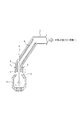
図1に、上述の転炉および転炉上部の排ガス回収設備を示す。図中、1は転炉、2は炉口部、3は固定式水冷フード、4は昇降式スカート、5は排ガスダクト、6は煙道、7は煙道中の二酸化炭素還元剤供給ノズルおよび8はメインランスを示す。
前述したような転炉の排ガスを回収する場合、従来の転炉では、図1に示したように、転炉1の炉口部2には昇降式スカート4を下端部に装着した固定式水冷フード3が密接するように配置されており、炉口部2を昇降式スカート4によってシールする構造となっている。
また、固定式水冷フード3に続く排ガスダクト5には、ガス集塵設備が設置されており、排ガスを洗浄すると共に冷却している。また、排ガスの熱回収兼冷却用設備として、廃熱回収ボイラが設置されていることも多い。
FIG. 1 shows the above-described converter and exhaust gas recovery equipment at the top of the converter. In the figure, 1 is a converter, 2 is a furnace port part, 3 is a fixed water-cooled hood, 4 is a liftable skirt, 5 is an exhaust gas duct, 6 is a flue, 7 is a carbon dioxide reducing agent supply nozzle in the flue, and 8 Indicates the main lance.
In the case of recovering the exhaust gas of the converter as described above, in the conventional converter, as shown in FIG. 1, a fixed water cooling in which a
Further, a gas dust collecting facility is installed in the
排ガスエネルギー回収に関連した技術として、二酸化炭素還元剤、すなわち炭化水素系のガスと、CO2 やH2 Oを含むガスとを高温で反応させることによって、還元ガス(CO、H2ガス)を製造するガスの改質方法が種々提案されている。
例えば、製鉄所内のガスを利用するものとして、特許文献1には、転炉排ガス煙道の1300℃以上の排ガス中にメタンと水蒸気を添加して水性ガス反応を生起させることにより、排ガスの潜熱の増加をはかる転炉排ガスの回収方法が示されている。
また、特許文献2には、各種製鉄設備から発生する排ガスエネルギーを、排ガス回収設備により回収する際に、炭化水素を含む気体および/または液体を供給して、高温排ガス中の二酸化炭素および/または水蒸気と反応させつつ、高温排ガスの潜熱分を増大させる技術が開示されている。
As a technology related to exhaust gas energy recovery, reducing gas (CO, H 2 gas) is produced by reacting a carbon dioxide reducing agent, that is, a hydrocarbon-based gas, with a gas containing CO 2 or H 2 O at a high temperature. Various methods for reforming the gas to be produced have been proposed.
For example, as an example of using gas in a steel plant, Patent Document 1 discloses that the latent heat of exhaust gas is obtained by adding methane and water vapor to the exhaust gas at 1300 ° C. or higher in the converter exhaust gas flue to cause a water gas reaction. A method for recovering converter exhaust gas to increase the flow rate is shown.
Further, Patent Document 2 discloses that when exhaust gas energy generated from various steelmaking facilities is recovered by an exhaust gas recovery facility, a gas and / or liquid containing hydrocarbons is supplied, and carbon dioxide and / or A technique for increasing the latent heat content of high-temperature exhaust gas while reacting with water vapor is disclosed.
しかしながら、前記した従来の技術では、二酸化炭素還元剤の排ガス中への供給手段として、例えば、図1に示したような、煙道に設けた二酸化炭素還元剤供給ノズル7のみを利用していた。
この場合、ノズルから供給された二酸化炭素還元剤の流束の外側、すなわち、二酸化炭素還元剤の流束と転炉の排ガスとが接触する境界付近で、排ガスの改質反応が起こる。二酸化炭素還元剤供給ノズルに太径ノズルを用いると、二酸化炭素還元剤流束の流径が大きいので、二酸化炭素還元剤の流束中心部において、二酸化炭素還元剤と排ガスとが混合するまでに相当の時間がかかる。従って、二酸化炭素還元剤の流束中心部の反応速度は遅くなり、回収排ガスの潜熱分を高める効率が悪くなるという問題があった。
However, in the above-described conventional technique, as a means for supplying the carbon dioxide reducing agent into the exhaust gas, for example, only the carbon dioxide reducing
In this case, the reforming reaction of the exhaust gas occurs outside the flux of the carbon dioxide reducing agent supplied from the nozzle, that is, in the vicinity of the boundary between the flux of the carbon dioxide reducing agent and the exhaust gas of the converter. When a large diameter nozzle is used as the carbon dioxide reducing agent supply nozzle, the flow diameter of the carbon dioxide reducing agent flux is large, so that the carbon dioxide reducing agent and the exhaust gas are mixed in the central portion of the carbon dioxide reducing agent flux. It takes a considerable amount of time. Therefore, there has been a problem that the reaction rate at the center of the flux of the carbon dioxide reducing agent is slow, and the efficiency of increasing the latent heat content of the recovered exhaust gas is deteriorated.
一方、供給ノズルに細径ノズルを用いた場合、所定量の二酸化炭素還元剤を供給しようとすると、二酸化炭素還元剤の流速を速くする必要が生じる。しかし、二酸化炭素還元剤流速が速くなると、二酸化炭素還元剤供給ノズルと対向している煙道壁に二酸化炭素還元剤が当たることとなり、エロージョン現象等による煙道壁の損傷という懸念が生じる。 On the other hand, when a small-diameter nozzle is used as the supply nozzle, if a predetermined amount of carbon dioxide reducing agent is to be supplied, the flow rate of the carbon dioxide reducing agent needs to be increased. However, when the flow rate of the carbon dioxide reducing agent is increased, the carbon dioxide reducing agent hits the flue wall facing the carbon dioxide reducing agent supply nozzle, and there is a concern that the flue wall is damaged due to an erosion phenomenon or the like.
また、細径の二酸化炭素還元剤供給ノズルでは、ノズル部におけるガスの圧力損失が大きいので、二酸化炭素還元剤の供給量を確保するためには、二酸化炭素還元剤の供給圧力を上げる必要があるが、煙道中の排ガスはほぼ常圧のため、二酸化炭素還元剤を高圧で供給した場合には断熱膨張が生じて、二酸化炭素還元剤の温度が降下することとなる。このような温度降下現象が生じると、二酸化炭素還元剤と排ガスとの反応効率が著しく低下するため、操炉上の問題も生じる。
さらに、ブースターポンプやエアーコンプレッサー等の二酸化炭素還元剤の昇圧設備が必要となるため、経済性にも問題があった。
Further, in the small-diameter carbon dioxide reducing agent supply nozzle, the pressure loss of the gas in the nozzle portion is large, so in order to secure the supply amount of the carbon dioxide reducing agent, it is necessary to increase the supply pressure of the carbon dioxide reducing agent. However, since the exhaust gas in the flue is almost normal pressure, when the carbon dioxide reducing agent is supplied at a high pressure, adiabatic expansion occurs and the temperature of the carbon dioxide reducing agent drops. When such a temperature drop phenomenon occurs, the reaction efficiency between the carbon dioxide reducing agent and the exhaust gas is remarkably lowered.
Furthermore, there is a problem in economic efficiency because a booster facility for a carbon dioxide reducing agent such as a booster pump and an air compressor is required.
本発明は、上記した現状に鑑み開発されたもので、製鉄所内における転炉などの製鉄設備から発生する高温排ガスエネルギーを回収するに際し、回収排ガスの潜熱分を高めるために排ガスに供給する二酸化炭素還元剤を供給する方法を、その供給に用いる転炉酸素吹錬用のメインランスの配管構造と共に提供することを目的とする。 The present invention has been developed in view of the above-described situation, and carbon dioxide supplied to the exhaust gas in order to increase the latent heat content of the recovered exhaust gas when recovering the high-temperature exhaust gas energy generated from the iron making equipment such as the converter in the ironworks. It aims at providing the method of supplying a reducing agent with the piping structure of the main lance for converter oxygen blowing used for the supply.
すなわち、本発明の要旨構成は次のとおりである。
1.転炉での吹錬時に発生する高温の排ガスのエネルギーを回収するに際し、該排ガス中に、気体状および/または液体状の還元剤を供給し、該排ガス中の二酸化炭素と反応させて、該排ガス中の潜熱分を増大させる転炉排ガスエネルギーの回収方法において、 上記転炉の煙道中に設けた二酸化炭素還元剤供給ノズルより、上記還元剤を該煙道内部に向けて供給すると共に、上記転炉の酸素吹錬用メインランスに開孔位置を下部フード位置より上方に設けた副孔より、上記還元剤を該煙道の内壁面に向けて供給することを特徴とする二酸化炭素還元剤の供給方法。
That is, the gist configuration of the present invention is as follows.
1. When recovering the energy of the high-temperature exhaust gas generated during blowing in the converter, a gaseous and / or liquid reducing agent is supplied into the exhaust gas, and reacted with carbon dioxide in the exhaust gas, In the converter exhaust gas energy recovery method for increasing the latent heat content in the exhaust gas, the reducing agent is supplied from the carbon dioxide reducing agent supply nozzle provided in the flue of the converter toward the inside of the flue, and A carbon dioxide reducing agent, characterized in that the reducing agent is supplied toward the inner wall surface of the flue from a sub-hole provided in the main lance for oxygen blowing of the converter with an opening position above the lower hood position. Supply method.
2.前記二酸化炭素還元剤供給ノズルから供給する還元剤と、前記酸素吹錬用メインランスの副孔から供給する還元剤とが異種の還元剤であることを特徴とする前記1に記載の二酸化炭素還元剤の供給方法。 2. 2. The carbon dioxide reduction according to 1 above, wherein the reducing agent supplied from the carbon dioxide reducing agent supply nozzle and the reducing agent supplied from a sub-hole of the main lance for oxygen blowing are different reducing agents. Agent supply method.
3.前記1または2に記載の二酸化炭素還元剤の供給に用いる酸素吹錬用のメインランスであって、該メインランスが二酸化炭素還元剤の供給用の副孔を有し、該副孔の開孔位置が下部フード位置より上方に設けられ、該副孔から上部のランス構造は、配管中心より酸素用管、二酸化炭素還元剤管、冷却水供給管および冷却水回収管の4重管構造になり、一方、該副孔より下部のランス構造は、配管中心より酸素用管、冷却水供給管および冷却水回収管の3重管構造になることを特徴とする転炉酸素吹錬用のメインランス。 3. 3. A main lance for oxygen blowing used for supplying the carbon dioxide reducing agent according to 1 or 2, wherein the main lance has a sub hole for supplying the carbon dioxide reducing agent, and the sub hole is opened. The lance structure is located above the lower hood position, and the lance structure above the auxiliary hole has a quadruple structure consisting of an oxygen pipe, a carbon dioxide reducing agent pipe, a cooling water supply pipe and a cooling water recovery pipe from the center of the pipe. On the other hand, the lance structure below the auxiliary hole has a triple pipe structure consisting of an oxygen pipe, a cooling water supply pipe, and a cooling water recovery pipe from the center of the pipe. .
4.前記メインランスの副孔の開孔位置が、さらにランスホールコーン位置より下方に設けられていることを特徴とする前記3に記載の転炉酸素吹錬用のメインランス。 4). The main lance opening position of the auxiliary hole is further main lance for converter oxygen blowing according to the 3, characterized in that provided below side than lance hole cone position.
本発明によれば、転炉などの製鉄設備から発生する高温排ガスの持つ熱エネルギーを、CO、H2 ガスという潜熱エネルギーに、極めて効率良く転換することができる。従って、製鉄工場全体として、極めて高いレベルでの省エネルギーを達成することができる。 According to the present invention, the thermal energy of high-temperature exhaust gas generated from a steelmaking facility such as a converter can be very efficiently converted into latent heat energy such as CO and H 2 gas. Therefore, it is possible to achieve energy saving at an extremely high level as a whole steel factory.
以下、本発明を具体的に説明する。
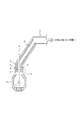
図2に、本発明に従う転炉設備の模式図を示す。なお、図中、1〜8は、図1と同等の機能を持つ設備であり、それぞれ図1に示した設備と同じ設備は同じ番号で示している。9はメインランスの副孔を示す。また、図3(a)〜(c)に、従来の転炉酸素吹錬用のメインランスの縦方向および横方向の断面図を示す。さらに、図4に、本発明に従う転炉酸素吹錬用のメインランスの縦方向および横方向の断面図を示す。
Hereinafter, the present invention will be specifically described.
In FIG. 2, the schematic diagram of the converter equipment according to this invention is shown. In the figure, reference numerals 1 to 8 denote facilities having functions equivalent to those in FIG. 1, and the same facilities as those shown in FIG. 9 denotes a sub-hole of the main lance. 3 (a) to 3 (c) are longitudinal and lateral sectional views of a conventional main lance for converter oxygen blowing. Further, FIG. 4 shows longitudinal and lateral sectional views of a main lance for converter oxygen blowing according to the present invention.
図2における転炉1からは、主にCO、CO2 、N2ガスがそれぞれ発生している。吹錬操業の時期や吹錬条件によっても異なるが、転炉炉口2の周辺での排ガス温度は概ね1200℃〜1800℃となっている。炉口2付近では、周囲の大気を多少吹い込んでいるため、大気中の酸素により、炉内から上昇してくるCOの一部が燃焼してCO2 になり、排ガス温度がその分上昇する。なお、回収されるガス中に含まれるN2は、この吸い込み大気(空気)に由来する。 From the converter 1 in FIG. 2, CO, CO 2 and N 2 gases are mainly generated. Although it differs depending on the timing of blowing operation and blowing conditions, the exhaust gas temperature around the converter furnace port 2 is approximately 1200 ° C to 1800 ° C. In the vicinity of the furnace port 2, since the surrounding atmosphere is blown in a little, a part of CO rising from the furnace is burned by the oxygen in the atmosphere to become CO 2 , and the exhaust gas temperature is increased accordingly. . Note that N 2 contained in the recovered gas is derived from this suction atmosphere (air).
本発明では、転炉炉口の上方に位置する固定式水冷フード3に設けられた煙道中の二酸化炭素還元剤供給ノズル7(以下、単に還元剤供給ノズル7という)から、炭化水素等の気体および/または液体の二酸化炭素還元剤(以下、単に還元剤という)を、排ガス回収設備の煙道6内部に向けて供給すると共に、転炉酸素吹錬用のメインランス8に設けられた副孔9(以下、単に副孔9という)から煙道の内壁面に向けて、上記の還元剤を供給する点に特徴がある。
還元剤供給ノズル7から還元剤を供給する場合は、煙道の中心方向に向かって供給することが好ましく、また副孔9から還元剤を供給する場合は、煙道の内壁面に向けて、放射状に供給することが好ましい。
In the present invention, from a carbon dioxide reducing agent supply nozzle 7 (hereinafter simply referred to as a reducing agent supply nozzle 7) in a flue provided in a fixed water-cooled
When supplying the reducing agent from the reducing
上記のように供給された還元剤は、煙道内のCO2 を含む高温ガスから熱を吸収して、以下の式に示す反応式(1)によりCOとH2 を生成する。なお、この式では、炭化水素の代表例として、天然ガスやコークス炉ガスに含まれるメタンについて示した。また、煙道中には水蒸気(H2O)が含まれる場合があるが、この場合にも、同様の反応によりH2が生成される。
これらの反応により、排ガスの潜熱分を効果的に増大することができる。
CH4 + CO2 → 2CO +2H2 、ΔH = +62 kcal ・・・反応式(1)
The reducing agent supplied as described above absorbs heat from the high-temperature gas containing CO 2 in the flue, and generates CO and H 2 according to the reaction formula (1) shown below. In this equation, methane contained in natural gas and coke oven gas is shown as a representative example of hydrocarbon. Further, the flue may contain water vapor (H 2 O). In this case as well, H 2 is generated by the same reaction.
By these reactions, the latent heat content of the exhaust gas can be effectively increased.
CH 4 + CO 2 → 2CO + 2H 2 , ΔH = +62 kcal ... Reaction formula (1)
本発明では、煙道の還元剤供給ノズル7およびメインランスの副孔9の両方から還元剤を供給することで、一つのノズル当たりの還元剤の供給量を、従来より低減することができる。そのため、煙道の還元剤供給ノズル7および副孔9のそれぞれが複数箇所設けられていることが望ましい。
なお、本発明では、還元剤供給ノズル7は、2〜5箇所程度、副孔9は、5〜10箇所程度設けることが好ましい。
In the present invention, by supplying the reducing agent from both the reducing
In the present invention, it is preferable to provide the reducing
上述したように、本発明では、還元剤の供給箇所を煙道の中央部と内壁部とすることで、供給ノズルや副孔を細径ノズルとした場合でも、還元剤の供給流速を上げる必要はなくなる。また、供給圧力も上げる必要がないため、断熱膨張の発生による温度低下現象も抑えられて、ブースターポンプやエアーコンプレッサーといった還元剤を加圧するための追加の昇圧設備も不要となる。 As described above, in the present invention, it is necessary to increase the supply flow rate of the reducing agent even when the supply nozzle and the sub-hole are made into a small-diameter nozzle by setting the supply portion of the reducing agent to the central portion and the inner wall portion of the flue. Will disappear. Further, since there is no need to increase the supply pressure, the temperature decrease phenomenon due to the occurrence of adiabatic expansion can be suppressed, and an additional boosting facility for pressurizing the reducing agent such as a booster pump or an air compressor is not necessary.
すなわち、本発明は、供給ノズルや副孔に細径配管を用いることで、供給する二酸化炭素還元剤の流束の流径を従来より細くすることができるため、転炉排ガスと還元剤と効率よく接触させることができる。なお、副孔の細径配管としては、直径:15〜25mm程度の円が好ましいが、短径を15〜25mm程度、長径を50〜100mm程度とした楕円でも良い。また、供給ノズルの細径配管としては、30〜50 mm程度の円が好ましい。 That is, according to the present invention, the flow diameter of the flux of the carbon dioxide reducing agent to be supplied can be made thinner than before by using a thin pipe for the supply nozzle and the auxiliary hole. Can be contacted well. In addition, as a small diameter piping of a subhole, a circle with a diameter of about 15 to 25 mm is preferable, but an ellipse with a minor axis of about 15 to 25 mm and a major axis of about 50 to 100 mm may be used. Moreover, as a thin diameter piping of a supply nozzle, a circle of about 30 to 50 mm is preferable.
また、本発明では、副孔9の近傍のようにガス温度が高く、反応効率を上げることができる領域に、効果的に還元剤を供給することが出来る。さらに、本発明では、還元剤供給ノズル7からも還元剤を供給することで、転炉ダクトの折れ曲がり部に排ガスの偏流が生じて、未反応となる排ガスが滞留するところ、すなわち排ガス中のCO2濃度が高めになるところを、還元剤で狙い打ちすることができるので、顕熱の回収効率をさらに効果的に高めることができるのである。
Moreover, in this invention, a reducing agent can be effectively supplied to the area | region where gas temperature is high like the vicinity of the
ここで、煙道内に供給する還元剤としては、以下のうちから選ばれる1種または2種以上の還元剤が好適に使用できる。すなわち、天然ガス、液化石油ガス、メタン、エタン、軽質ナフサ、ラフィネート、メタノール、エタノール、ジメチルエーテル、ジエチルエーテル、非化石資源系有機化合物などである。 Here, as the reducing agent supplied into the flue, one or more reducing agents selected from the following can be suitably used. That is, natural gas, liquefied petroleum gas, methane, ethane, light naphtha, raffinate, methanol, ethanol, dimethyl ether, diethyl ether, non-fossil resource-based organic compounds, and the like.
本発明において、副孔9と還元剤供給ノズル7から供給する還元剤は、上記したもののうち、同種のものであっても良いが、異種のものであっても良い。特に、副孔9付近は雰囲気温度が高いので、反応効率を飛躍的に向上できるという利点があるため、例えば、天然ガスを還元剤として用いることが好適できる。
In the present invention, the reducing agent supplied from the sub-hole 9 and the reducing
また、還元剤供給ノズル7の位置を、前述したような転炉排ガスの未反応の領域を狙う場所とすることで、還元剤と転炉排ガスとの反応むらを低減することができ、反応効率の向上を図ることができる。
Further, by setting the position of the reducing
これら還元剤の供給量および供給圧力は、排ガス中に含まれるCO2 やH2 Oを還元ガスとするのに十分な量および圧力とすれば良いが、排ガス中のCO2 やH2 Oの含有量は、転炉等の形式や製錬反応の種類に依存し、還元反応の反応効率も還元剤の種類や吹込み口数などによって異なるのが一般的である。従って、還元剤の供給量および供給圧力は、これら種々の条件を勘案して決定することが望ましい。 The supply amount and supply pressure of these reducing agents may be sufficient amounts and pressures to use CO 2 or H 2 O contained in the exhaust gas as a reducing gas, but the amount of CO 2 or H 2 O in the exhaust gas The content depends on the type of the converter and the type of smelting reaction, and the reaction efficiency of the reduction reaction is generally different depending on the type of reducing agent, the number of blowing ports, and the like. Therefore, it is desirable to determine the supply amount and supply pressure of the reducing agent in consideration of these various conditions.
上記した供給量の具体的な例としては、転炉排ガス流量:150km3(N)/hに対し、ガス供給ノズル7から供給する還元剤の流量を100〜10000m3(N)/h程度、他方、副孔9から供給する還元剤の流量を100〜5000m3(N)/h程度とすることが好ましい。
As a specific example of the above supply amount, the flow rate of the reducing agent supplied from the
というのは、ガス供給ノズル7から供給する還元剤の流量が100m3(N)/hに満たない場合は、改質効果が小さすぎて、設備投資に見合わない。一方、10000m3(N)/hを超えた場合は、還元剤量が過大となり、還元剤の一部が未反応となる効率的な改質ができない。また、これだけの流量を流すためには、昇圧設備が必要となるなど、前述した経済性などの問題が発生する。また、副孔9から供給する還元剤の流量が100m3(N)/hに満たない場合は、やはり改質効果が小さすぎて、設備投資に見合わない。一方、5000m3(N)/hを超えた場合は、ガス供給ノズル7と同様、未反応となる還元剤が生じる可能性があり、かつ前述した経済性などの問題が発生する。
This is because when the flow rate of the reducing agent supplied from the
上記した供給圧力の具体的な例としては、還元剤供給ノズル7から供給する還元剤の圧力を0.2〜10MPaとし、副孔9から供給する還元剤の圧力を0.2〜10MPaとすることが好ましい。より好ましくは、還元剤供給ノズル7から供給する圧力を0.2〜5MPaとし、副孔9から供給する圧力を0.2〜5MPaとする。
As a specific example of the supply pressure described above, the pressure of the reducing agent supplied from the reducing
本発明に従う酸素吹錬用メインランスは、図4に示したとおり、還元剤供給のための副孔9を有していることに特徴がある。従って、上記副孔9から上部は、配管中心より酸素用管、還元剤用管、冷却水供給管および冷却水回収管の4重管構造になり、さらに副孔9より下部は、配管中心より酸素用管、冷却水供給管および冷却水回収管の3重管構造になる。 As shown in FIG. 4, the main lance for oxygen blowing according to the present invention is characterized by having a sub-hole 9 for supplying a reducing agent. Accordingly, the upper part from the sub-hole 9 has a quadruple structure of an oxygen pipe, a reducing agent pipe, a cooling water supply pipe and a cooling water recovery pipe from the center of the pipe, and the lower part from the sub-hole 9 is from the center of the pipe. It has a triple pipe structure of an oxygen pipe, a cooling water supply pipe and a cooling water recovery pipe.
ここに、上記したメインランスの配管の配管径は転炉等の設備の規模に応じて適宜設計することができるが、好適な外径としては、メインランスの副孔より上部の外径は、酸素用管が60.5〜1016mm、還元剤用管が114.3〜1016mm、冷却水供給管が165.2〜1016mmおよび冷却水回収管が216.3〜1016mmである。
また、メインランスの副孔より下部の外径は、酸素用管が60.5〜1016mm、冷却水供給管が114.3〜1016mmおよび冷却水回収管が165.2〜1016mmである。
Here, the pipe diameter of the main lance pipe described above can be appropriately designed according to the scale of equipment such as a converter, but as a suitable outer diameter, the outer diameter above the sub-hole of the main lance is: The oxygen pipe is 60.5 to 1016 mm, the reducing agent pipe is 114.3 to 1016 mm, the cooling water supply pipe is 165.2 to 1016 mm, and the cooling water recovery pipe is 216.3 to 1016 mm.
The outer diameter of the main lance below the sub-hole is 60.5 to 1016 mm for the oxygen pipe, 114.3 to 1016 mm for the cooling water supply pipe, and 165.2 to 1016 mm for the cooling water recovery pipe.
本発明に従う副孔9の開孔位置は、ランスホールコーン位置より下方で、還元剤供給ノズル7の開孔位置より下方とする一方、下部フード位置より上方に設けることが好ましい。というのは、副孔9の開孔位置が還元剤供給ノズル7の開孔位置に対して上方に位置した場合には、副孔9から吹き込んだ二酸化炭素還元剤と排ガスとの未反応領域に対して、還元剤供給ノズル7から効果的に還元剤を吹き込むことができなくなるからである。一方、副孔9の開孔位置が、下部フード位置より下方になると、還元されるべき二酸化炭素が存在していないからである。
The opening position of the sub-hole 9 according to the present invention is preferably provided below the lance hole cone position and below the opening position of the reducing
また、副孔9の開孔位置が副原料投射口より下方にあると、投射された副原料(鉄鋼石など)がランス副孔に詰まる可能性があるため、副原料投射口より上方にあることが好ましい。
Further, if the opening position of the
還元剤供給ノズル7の開孔位置は、従来の転炉排ガス設備の開孔位置で特に問題はないが、上述したように、副孔9から吹き込んだ二酸化炭素還元剤と排ガスとの未反応領域に吹き込むことができる位置であって、かつ転炉操業の妨げにならない位置とするのが望ましい。
本発明における還元剤供給ノズル7は、前述した口径で、かつ煙道の側壁に設けた吹込み口あるいは煙道内にパイプなどを挿入して吹込む形状などが好ましいが、特にこれらに限定するものではない。
Although the opening position of the reducing
The reducing
以上、本発明を転炉に用いた場合を詳述したが、本発明は、メインランスを備える各種の製鉄設備で使用することができる。具体的には、通常の製鋼用転炉、溶融還元炉、合金鉄製造炉等があり、いずれも排ガスの顕熱と潜熱を回収する設備を有するものである。 As mentioned above, although the case where this invention was used for the converter was explained in full detail, this invention can be used with the various steel manufacturing equipment provided with a main lance. Specifically, there are an ordinary steelmaking converter, a smelting reduction furnace, an alloy iron production furnace, etc., all of which have facilities for recovering sensible heat and latent heat of exhaust gas.
図2に示した方式に従う250tonの転炉を用いて、本発明を実験した例を示す。なお、以下の%表示は特に断らない限りmol%である。
通常、この転炉には1000 m3(N)/minの酸素ガスをメインランスから供給する。炉内の脱炭反応によりCOガスが発生し、炉口部分で一部空気を吸い込むため、回収される排ガスの成分は、CO=60%、CO2 =15%、H2=0.5%、N2=24.5%である。排ガス総量は1400 m3(N)/min である。使用した還元剤は都市ガスであり、CH4 を89.6%、その他の炭化水素ガスを10.4%含んでいた。このガスは、ほぼCH4 として扱ってよいので、前述した反応式(1)に従えば、反応によって発生するガス量が推定できる。さらに、煙道後段に設置されている排ガスブロワの設備能力を考慮すると、吹込み可能な都市ガスは100 m3(N)/min であり、これを図2の還元剤供給ノズル7および/または副孔9から煙道内に吹き込んだ。
還元剤供給ノズル7の開口位置は、スカート部から3000mm上方であり、副孔9の開口位置は、スカート部から1000mm上方である。
The example which experimented this invention using the 250-ton converter according to the system shown in FIG. 2 is shown. In addition, the following% display is mol% unless otherwise indicated.
Normally, this converter is supplied with 1000 m 3 (N) / min of oxygen gas from the main lance. Since CO gas is generated by the decarburization reaction in the furnace and a part of the air is sucked in at the furnace port, the components of the recovered exhaust gas are CO = 60%, CO 2 = 15%, H 2 = 0.5%, N 2 = 24.5%. The total amount of exhaust gas is 1400 m 3 (N) / min. The reducing agent used was city gas, containing 89.6% CH 4 and 10.4% other hydrocarbon gases. Since this gas may be handled as almost CH 4 , the amount of gas generated by the reaction can be estimated according to the above-described reaction formula (1). Furthermore, considering the facility capacity of the exhaust gas blower installed in the latter stage of the flue, the city gas that can be blown is 100 m 3 (N) / min, and this is reduced to the reducing
The opening position of the reducing
具体的な、還元剤の供給条件は、表1に示すとおりである。ここに、還元剤供給ノズル7は煙道の円周上に2本設置し、副孔9は8箇所に設けた。また、メインランスの構造は、図4と同じものとし、メインランスの副孔より上部の外径は、酸素用管を216.3mm、還元剤用管を267.4mm、冷却水供給管を355.6mmおよび冷却水回収管を406.4mmとし、メインランスの副孔より下部の外径は、酸素用管を216.3mm、冷却水供給管を318.5mmおよび冷却水回収管を406.4mmとした。
煙道上部の位置から採取し分析した排ガス組成を表1に併記する。
Specific supply conditions of the reducing agent are as shown in Table 1. Here, two reducing
The exhaust gas composition collected and analyzed from the upper part of the flue is also shown in Table 1.

同表より、還元剤を供給していないときは、組成は前述と同じ、排ガス流量は140km3(N)/h、排ガスの持つ総熱量は240.8Gcal/hであったのに対し、還元剤供給ノズル7のみから供給したときの組成は、CO=60.1%、CO2=13.1%、H2=2.3%、
N2=23.5%、流量は145.8km3(N)/hであった。このときの排ガスの持つ熱量は267.2Gcal/hであった。
また、本発明に従い、還元剤供給ノズル7および副孔9の両方から還元剤を供給した場合の組成は、CO=59.6%、CO2 =11.3%、H2=3.9%、N2=22.5%、排ガス流量は152.6km3(N)/h、排ガスの持つ総熱量は304.1Gcal/hであった。
From the table, when the reducing agent is not supplied, the composition is the same as above, the exhaust gas flow rate is 140 km 3 (N) / h, and the total calorific value of the exhaust gas is 240.8 Gcal / h. The composition when supplied only from the
N 2 = 23.5% and the flow rate was 145.8 km 3 (N) / h. The amount of heat of the exhaust gas at this time was 267.2 Gcal / h.
Further, according to the present invention, the composition when the reducing agent is supplied from both the reducing
従って、本発明に従い、還元剤供給ノズル7および副孔9の両方から還元剤を供給した場合はいずれも、従来例および比較例に比べてCO、H2量が増大している。なお、この排ガスの潜熱分を計算した結果、本発明に従う実施例は、いずれも排ガスの持つ総熱量が向上していたが、例えば、試験No.4は、単位時間あたり、従来例(試験No.1)に比べて63.3Gcal程度、また比較例(試験No.2)に比べて36.9Gcal程度向上していることが確認された。
Therefore, according to the present invention, when the reducing agent is supplied from both the reducing
1 転炉
2 炉口部
3 固定式水冷フード
4 昇降式スカート
5 排ガスダクト
6 煙道
7 煙道中の二酸化炭素還元剤供給ノズル
8 メインランス
9 メインランスの副孔
DESCRIPTION OF SYMBOLS 1 Converter 2
Claims (4)
Priority Applications (1)
| Application Number | Priority Date | Filing Date | Title |
|---|---|---|---|
| JP2011060676A JP5760552B2 (en) | 2011-03-18 | 2011-03-18 | Carbon dioxide reducing agent supply method and main lance for converter oxygen blowing |
Applications Claiming Priority (1)
| Application Number | Priority Date | Filing Date | Title |
|---|---|---|---|
| JP2011060676A JP5760552B2 (en) | 2011-03-18 | 2011-03-18 | Carbon dioxide reducing agent supply method and main lance for converter oxygen blowing |
Publications (2)
| Publication Number | Publication Date |
|---|---|
| JP2012197465A JP2012197465A (en) | 2012-10-18 |
| JP5760552B2 true JP5760552B2 (en) | 2015-08-12 |
Family
ID=47179983
Family Applications (1)
| Application Number | Title | Priority Date | Filing Date |
|---|---|---|---|
| JP2011060676A Active JP5760552B2 (en) | 2011-03-18 | 2011-03-18 | Carbon dioxide reducing agent supply method and main lance for converter oxygen blowing |
Country Status (1)
| Country | Link |
|---|---|
| JP (1) | JP5760552B2 (en) |
Families Citing this family (3)
| Publication number | Priority date | Publication date | Assignee | Title |
|---|---|---|---|---|
| CN109880956B (en) * | 2019-04-17 | 2024-09-06 | 中国恩菲工程技术有限公司 | Smelting system for short-process processing of iron-based polymetallic ore |
| CN114635012A (en) * | 2022-03-25 | 2022-06-17 | 马鞍山乌力平冶金技术工作室 | Method and device for recycling residual energy of smoke of steel making furnace |
| CN115975681A (en) * | 2023-01-15 | 2023-04-18 | 武汉市赟巨科技有限公司 | Entrained high temperature and high pressure gasification reactor combined with metallurgical equipment and method for recycling metallurgical furnace flue gas |
Family Cites Families (10)
| Publication number | Priority date | Publication date | Assignee | Title |
|---|---|---|---|---|
| JPS61139616A (en) * | 1984-12-11 | 1986-06-26 | Nisshin Steel Co Ltd | Method for removing accretion on throat of converter |
| JP2000282128A (en) * | 1999-03-31 | 2000-10-10 | Kawasaki Steel Corp | Cooling method for furnace fittings and refractories of smelting and refining vessels |
| JP5476792B2 (en) * | 2008-05-16 | 2014-04-23 | Jfeスチール株式会社 | Method for reforming exhaust gas generated from metallurgical furnace, reformer, and method for producing reformed gas |
| CA2721329C (en) * | 2008-05-16 | 2012-04-10 | Jfe Steel Corporation | Method for reforming exhaust gas generated from metallurgical furnace, method for cooling exhaust gas and apparatus therefor |
| JP5453760B2 (en) * | 2008-10-22 | 2014-03-26 | Jfeスチール株式会社 | Method and apparatus for reforming and increasing heat of exhaust gas generated from metallurgical furnace |
| JP5487607B2 (en) * | 2008-12-16 | 2014-05-07 | Jfeスチール株式会社 | Method and apparatus for reforming exhaust gas generated from metallurgical furnace |
| JP5439859B2 (en) * | 2009-02-27 | 2014-03-12 | Jfeスチール株式会社 | Method and apparatus for reforming exhaust gas generated from metallurgical furnace |
| JP2010223573A (en) * | 2009-02-27 | 2010-10-07 | Jfe Steel Corp | Method and apparatus for cooling exhaust gas generated from metallurgical furnace |
| JP2011021236A (en) * | 2009-07-15 | 2011-02-03 | Jfe Steel Corp | Method of reforming exhaust gas generated from metallurgical furnace |
| JP5471154B2 (en) * | 2009-08-20 | 2014-04-16 | Jfeスチール株式会社 | Method and equipment for reforming exhaust gas containing carbon dioxide |
-
2011
- 2011-03-18 JP JP2011060676A patent/JP5760552B2/en active Active
Also Published As
| Publication number | Publication date |
|---|---|
| JP2012197465A (en) | 2012-10-18 |
Similar Documents
| Publication | Publication Date | Title |
|---|---|---|
| US10072312B2 (en) | Method for operating a top gas recycling blast furnace installation | |
| US8765087B2 (en) | Method for reforming exhaust gas generated from metallurgical furnace, method for cooling exhaust gas and apparatus therefor | |
| JP4661890B2 (en) | Blast furnace operation method | |
| US20150068364A1 (en) | Blast furnace with top-gas recycle | |
| JP4702309B2 (en) | Blast furnace operation method | |
| JP2015525829A (en) | Method and system for operating a blast furnace with furnace top gas recirculation and combustion tubular furnace | |
| KR20120031003A (en) | Method for operating a regenerative heater | |
| JP5760552B2 (en) | Carbon dioxide reducing agent supply method and main lance for converter oxygen blowing | |
| JP2000212615A (en) | Energy recovery method from exhaust gas from steelmaking equipment | |
| JP5453760B2 (en) | Method and apparatus for reforming and increasing heat of exhaust gas generated from metallurgical furnace | |
| JP5476987B2 (en) | Blast furnace operation method | |
| JP5509676B2 (en) | How to operate a vertical furnace | |
| WO2019150204A1 (en) | Nitrogen-free pig iron smelting technology with oxygen and carbon dioxide blown into a blast furnace | |
| JP5581657B2 (en) | Heat energy recovery method and apparatus for converter exhaust gas | |
| JP5470920B2 (en) | Metallurgical furnace exhaust gas reforming equipment | |
| JP5487607B2 (en) | Method and apparatus for reforming exhaust gas generated from metallurgical furnace | |
| JP6191707B2 (en) | Converter gas recovery method | |
| JP5540658B2 (en) | Thermal energy recovery method for exhaust gas generated from metallurgical furnace | |
| JP5581656B2 (en) | Heat energy recovery method and apparatus for converter exhaust gas | |
| JP2011102680A (en) | Method for recovering sensible heat of exhaust gas and method of cooling exhaust gas | |
| JP5549056B2 (en) | Blast furnace operation method | |
| JPH06128614A (en) | Blast furnace operation method | |
| JP7626237B2 (en) | Blast furnace operation method and blast furnace | |
| JP7836025B2 (en) | Method for injecting reducing gas into a blast furnace and blast furnace | |
| KR101239419B1 (en) | Method and Apparatus for Manufacturing Molten Irons |
Legal Events
| Date | Code | Title | Description |
|---|---|---|---|
| A621 | Written request for application examination |
Free format text: JAPANESE INTERMEDIATE CODE: A621 Effective date: 20140220 |
|
| A977 | Report on retrieval |
Free format text: JAPANESE INTERMEDIATE CODE: A971007 Effective date: 20141010 |
|
| A131 | Notification of reasons for refusal |
Free format text: JAPANESE INTERMEDIATE CODE: A131 Effective date: 20141118 |
|
| A521 | Request for written amendment filed |
Free format text: JAPANESE INTERMEDIATE CODE: A523 Effective date: 20150116 |
|
| TRDD | Decision of grant or rejection written | ||
| A01 | Written decision to grant a patent or to grant a registration (utility model) |
Free format text: JAPANESE INTERMEDIATE CODE: A01 Effective date: 20150512 |
|
| A61 | First payment of annual fees (during grant procedure) |
Free format text: JAPANESE INTERMEDIATE CODE: A61 Effective date: 20150525 |
|
| R150 | Certificate of patent or registration of utility model |
Ref document number: 5760552 Country of ref document: JP Free format text: JAPANESE INTERMEDIATE CODE: R150 |
|
| R250 | Receipt of annual fees |
Free format text: JAPANESE INTERMEDIATE CODE: R250 |
|
| R250 | Receipt of annual fees |
Free format text: JAPANESE INTERMEDIATE CODE: R250 |
|
| R250 | Receipt of annual fees |
Free format text: JAPANESE INTERMEDIATE CODE: R250 |
|
| R250 | Receipt of annual fees |
Free format text: JAPANESE INTERMEDIATE CODE: R250 |
|
| R250 | Receipt of annual fees |
Free format text: JAPANESE INTERMEDIATE CODE: R250 |