JP5759900B2 - Anchor-in-anchor system for use in bone fixation - Google Patents
Anchor-in-anchor system for use in bone fixation Download PDFInfo
- Publication number
- JP5759900B2 JP5759900B2 JP2011539738A JP2011539738A JP5759900B2 JP 5759900 B2 JP5759900 B2 JP 5759900B2 JP 2011539738 A JP2011539738 A JP 2011539738A JP 2011539738 A JP2011539738 A JP 2011539738A JP 5759900 B2 JP5759900 B2 JP 5759900B2
- Authority
- JP
- Japan
- Prior art keywords
- anchor
- bone
- head
- shaft
- fixation
- Prior art date
- Legal status (The legal status is an assumption and is not a legal conclusion. Google has not performed a legal analysis and makes no representation as to the accuracy of the status listed.)
- Active
Links
Images


Classifications
-
- A—HUMAN NECESSITIES
- A61—MEDICAL OR VETERINARY SCIENCE; HYGIENE
- A61B—DIAGNOSIS; SURGERY; IDENTIFICATION
- A61B17/00—Surgical instruments, devices or methods, e.g. tourniquets
- A61B17/56—Surgical instruments or methods for treatment of bones or joints; Devices specially adapted therefor
- A61B17/58—Surgical instruments or methods for treatment of bones or joints; Devices specially adapted therefor for osteosynthesis, e.g. bone plates, screws, setting implements or the like
- A61B17/68—Internal fixation devices, including fasteners and spinal fixators, even if a part thereof projects from the skin
- A61B17/70—Spinal positioners or stabilisers ; Bone stabilisers comprising fluid filler in an implant
- A61B17/7001—Screws or hooks combined with longitudinal elements which do not contact vertebrae
- A61B17/7032—Screws or hooks with U-shaped head or back through which longitudinal rods pass
-
- A—HUMAN NECESSITIES
- A61—MEDICAL OR VETERINARY SCIENCE; HYGIENE
- A61B—DIAGNOSIS; SURGERY; IDENTIFICATION
- A61B17/00—Surgical instruments, devices or methods, e.g. tourniquets
- A61B17/56—Surgical instruments or methods for treatment of bones or joints; Devices specially adapted therefor
- A61B17/58—Surgical instruments or methods for treatment of bones or joints; Devices specially adapted therefor for osteosynthesis, e.g. bone plates, screws, setting implements or the like
- A61B17/68—Internal fixation devices, including fasteners and spinal fixators, even if a part thereof projects from the skin
- A61B17/80—Cortical plates, i.e. bone plates; Instruments for holding or positioning cortical plates, or for compressing bones attached to cortical plates
-
- A—HUMAN NECESSITIES
- A61—MEDICAL OR VETERINARY SCIENCE; HYGIENE
- A61B—DIAGNOSIS; SURGERY; IDENTIFICATION
- A61B17/00—Surgical instruments, devices or methods, e.g. tourniquets
- A61B17/56—Surgical instruments or methods for treatment of bones or joints; Devices specially adapted therefor
- A61B17/58—Surgical instruments or methods for treatment of bones or joints; Devices specially adapted therefor for osteosynthesis, e.g. bone plates, screws, setting implements or the like
- A61B17/68—Internal fixation devices, including fasteners and spinal fixators, even if a part thereof projects from the skin
- A61B17/72—Intramedullary pins, nails or other devices
- A61B17/7233—Intramedullary pins, nails or other devices with special means of locking the nail to the bone
- A61B17/7241—Intramedullary pins, nails or other devices with special means of locking the nail to the bone the nail having separate elements through which screws pass
-
- A—HUMAN NECESSITIES
- A61—MEDICAL OR VETERINARY SCIENCE; HYGIENE
- A61B—DIAGNOSIS; SURGERY; IDENTIFICATION
- A61B17/00—Surgical instruments, devices or methods, e.g. tourniquets
- A61B17/56—Surgical instruments or methods for treatment of bones or joints; Devices specially adapted therefor
- A61B17/58—Surgical instruments or methods for treatment of bones or joints; Devices specially adapted therefor for osteosynthesis, e.g. bone plates, screws, setting implements or the like
- A61B17/68—Internal fixation devices, including fasteners and spinal fixators, even if a part thereof projects from the skin
- A61B17/72—Intramedullary pins, nails or other devices
- A61B17/7233—Intramedullary pins, nails or other devices with special means of locking the nail to the bone
- A61B17/725—Intramedullary pins, nails or other devices with special means of locking the nail to the bone with locking pins or screws of special form
-
- A—HUMAN NECESSITIES
- A61—MEDICAL OR VETERINARY SCIENCE; HYGIENE
- A61B—DIAGNOSIS; SURGERY; IDENTIFICATION
- A61B17/00—Surgical instruments, devices or methods, e.g. tourniquets
- A61B17/56—Surgical instruments or methods for treatment of bones or joints; Devices specially adapted therefor
- A61B17/58—Surgical instruments or methods for treatment of bones or joints; Devices specially adapted therefor for osteosynthesis, e.g. bone plates, screws, setting implements or the like
- A61B17/68—Internal fixation devices, including fasteners and spinal fixators, even if a part thereof projects from the skin
- A61B17/80—Cortical plates, i.e. bone plates; Instruments for holding or positioning cortical plates, or for compressing bones attached to cortical plates
- A61B17/8033—Cortical plates, i.e. bone plates; Instruments for holding or positioning cortical plates, or for compressing bones attached to cortical plates having indirect contact with screw heads, or having contact with screw heads maintained with the aid of additional components, e.g. nuts, wedges or head covers
- A61B17/8038—Cortical plates, i.e. bone plates; Instruments for holding or positioning cortical plates, or for compressing bones attached to cortical plates having indirect contact with screw heads, or having contact with screw heads maintained with the aid of additional components, e.g. nuts, wedges or head covers the additional component being inserted in the screw head
-
- A—HUMAN NECESSITIES
- A61—MEDICAL OR VETERINARY SCIENCE; HYGIENE
- A61B—DIAGNOSIS; SURGERY; IDENTIFICATION
- A61B17/00—Surgical instruments, devices or methods, e.g. tourniquets
- A61B17/56—Surgical instruments or methods for treatment of bones or joints; Devices specially adapted therefor
- A61B17/58—Surgical instruments or methods for treatment of bones or joints; Devices specially adapted therefor for osteosynthesis, e.g. bone plates, screws, setting implements or the like
- A61B17/68—Internal fixation devices, including fasteners and spinal fixators, even if a part thereof projects from the skin
- A61B17/683—Internal fixation devices, including fasteners and spinal fixators, even if a part thereof projects from the skin comprising bone transfixation elements, e.g. bolt with a distal cooperating element such as a nut
-
- A—HUMAN NECESSITIES
- A61—MEDICAL OR VETERINARY SCIENCE; HYGIENE
- A61B—DIAGNOSIS; SURGERY; IDENTIFICATION
- A61B17/00—Surgical instruments, devices or methods, e.g. tourniquets
- A61B17/56—Surgical instruments or methods for treatment of bones or joints; Devices specially adapted therefor
- A61B17/58—Surgical instruments or methods for treatment of bones or joints; Devices specially adapted therefor for osteosynthesis, e.g. bone plates, screws, setting implements or the like
- A61B17/68—Internal fixation devices, including fasteners and spinal fixators, even if a part thereof projects from the skin
- A61B17/70—Spinal positioners or stabilisers ; Bone stabilisers comprising fluid filler in an implant
- A61B17/7001—Screws or hooks combined with longitudinal elements which do not contact vertebrae
- A61B17/7035—Screws or hooks, wherein a rod-clamping part and a bone-anchoring part can pivot relative to each other
- A61B17/7037—Screws or hooks, wherein a rod-clamping part and a bone-anchoring part can pivot relative to each other wherein pivoting is blocked when the rod is clamped
-
- A—HUMAN NECESSITIES
- A61—MEDICAL OR VETERINARY SCIENCE; HYGIENE
- A61B—DIAGNOSIS; SURGERY; IDENTIFICATION
- A61B17/00—Surgical instruments, devices or methods, e.g. tourniquets
- A61B17/56—Surgical instruments or methods for treatment of bones or joints; Devices specially adapted therefor
- A61B17/58—Surgical instruments or methods for treatment of bones or joints; Devices specially adapted therefor for osteosynthesis, e.g. bone plates, screws, setting implements or the like
- A61B17/68—Internal fixation devices, including fasteners and spinal fixators, even if a part thereof projects from the skin
- A61B17/70—Spinal positioners or stabilisers ; Bone stabilisers comprising fluid filler in an implant
- A61B17/7059—Cortical plates
-
- A—HUMAN NECESSITIES
- A61—MEDICAL OR VETERINARY SCIENCE; HYGIENE
- A61B—DIAGNOSIS; SURGERY; IDENTIFICATION
- A61B17/00—Surgical instruments, devices or methods, e.g. tourniquets
- A61B17/56—Surgical instruments or methods for treatment of bones or joints; Devices specially adapted therefor
- A61B17/58—Surgical instruments or methods for treatment of bones or joints; Devices specially adapted therefor for osteosynthesis, e.g. bone plates, screws, setting implements or the like
- A61B17/68—Internal fixation devices, including fasteners and spinal fixators, even if a part thereof projects from the skin
- A61B17/80—Cortical plates, i.e. bone plates; Instruments for holding or positioning cortical plates, or for compressing bones attached to cortical plates
- A61B17/8023—Variable length plates adjustable in both directions
-
- A—HUMAN NECESSITIES
- A61—MEDICAL OR VETERINARY SCIENCE; HYGIENE
- A61B—DIAGNOSIS; SURGERY; IDENTIFICATION
- A61B17/00—Surgical instruments, devices or methods, e.g. tourniquets
- A61B17/56—Surgical instruments or methods for treatment of bones or joints; Devices specially adapted therefor
- A61B17/58—Surgical instruments or methods for treatment of bones or joints; Devices specially adapted therefor for osteosynthesis, e.g. bone plates, screws, setting implements or the like
- A61B17/68—Internal fixation devices, including fasteners and spinal fixators, even if a part thereof projects from the skin
- A61B17/80—Cortical plates, i.e. bone plates; Instruments for holding or positioning cortical plates, or for compressing bones attached to cortical plates
- A61B17/8052—Cortical plates, i.e. bone plates; Instruments for holding or positioning cortical plates, or for compressing bones attached to cortical plates immobilised relative to screws by interlocking form of the heads and plate holes, e.g. conical or threaded
- A61B17/8057—Cortical plates, i.e. bone plates; Instruments for holding or positioning cortical plates, or for compressing bones attached to cortical plates immobilised relative to screws by interlocking form of the heads and plate holes, e.g. conical or threaded the interlocking form comprising a thread
-
- A—HUMAN NECESSITIES
- A61—MEDICAL OR VETERINARY SCIENCE; HYGIENE
- A61B—DIAGNOSIS; SURGERY; IDENTIFICATION
- A61B17/00—Surgical instruments, devices or methods, e.g. tourniquets
- A61B17/56—Surgical instruments or methods for treatment of bones or joints; Devices specially adapted therefor
- A61B17/58—Surgical instruments or methods for treatment of bones or joints; Devices specially adapted therefor for osteosynthesis, e.g. bone plates, screws, setting implements or the like
- A61B17/68—Internal fixation devices, including fasteners and spinal fixators, even if a part thereof projects from the skin
- A61B17/84—Fasteners therefor or fasteners being internal fixation devices
- A61B17/86—Pins or screws or threaded wires; nuts therefor
- A61B17/8605—Heads, i.e. proximal ends projecting from bone
-
- A—HUMAN NECESSITIES
- A61—MEDICAL OR VETERINARY SCIENCE; HYGIENE
- A61B—DIAGNOSIS; SURGERY; IDENTIFICATION
- A61B17/00—Surgical instruments, devices or methods, e.g. tourniquets
- A61B17/56—Surgical instruments or methods for treatment of bones or joints; Devices specially adapted therefor
- A61B17/58—Surgical instruments or methods for treatment of bones or joints; Devices specially adapted therefor for osteosynthesis, e.g. bone plates, screws, setting implements or the like
- A61B17/68—Internal fixation devices, including fasteners and spinal fixators, even if a part thereof projects from the skin
- A61B17/84—Fasteners therefor or fasteners being internal fixation devices
- A61B17/86—Pins or screws or threaded wires; nuts therefor
- A61B17/8685—Pins or screws or threaded wires; nuts therefor comprising multiple separate parts
Description
〔関連出願への相互参照〕
本出願は、2008年12月5日出願の米国特許出願出願番号第61/120,138号明細書の恩典を主張し、その開示は、その全体が本明細書において説明されるかのようにここで引用により組み込まれる。
[Cross-reference to related applications]
This application claims the benefit of US patent application Ser. No. 61 / 120,138, filed Dec. 5, 2008, the disclosure of which is as if fully set forth herein. Incorporated herein by reference.
本発明の開示は、一般的に整形外科に関し、特に、固定システム及び関連手術方法、並びにそれを使用するための手順に関する。 The present disclosure relates generally to orthopedics, and more particularly to fixation systems and related surgical methods and procedures for using the same.
骨又は骨片を復位するための様々な固定デバイスは、公知である。例えば、外部骨固定デバイス又は創外固定器は、人体の長骨の骨折部を復位するのに使用される。骨プレートのような内部骨固定デバイスも、骨折部を復位するのに一般的に使用される。椎間インプラント及び脊椎ロッドなどを含む脊椎固定デバイスは、椎間板を置換し、隣接する椎骨を融合又は整列させ、かつ他の脊椎問題に対処するのに使用される。 Various fixation devices for repositioning bones or bone fragments are known. For example, an external bone fixation device or external fixator is used to reposition a fracture of a long bone of a human body. Internal bone fixation devices such as bone plates are also commonly used to reposition fractures. Spinal fixation devices, including intervertebral implants and spinal rods, are used to replace intervertebral discs, fuse or align adjacent vertebrae, and address other spinal problems.
多数の固定デバイスは、スクリュー、ピン、及び釘などを含むことができる骨アンカーを使用して下にある骨に取り付けられる。例えば、典型的な骨プレートは、骨セグメントを互いに接合するために骨折部の両側の下にある骨にドリルで穴を開けられて骨スクリューに適合するスクリュー孔を含む。典型的な頸椎インプラントは、インプラントの位置を固定するために、隣接する椎体内にドリルで穴を開けられてスクリューに適合するスクリュー孔を同様に含むことができる。残念ながら、下にある骨への固定デバイスの取り付けは、例えば、スクリューが通常の身体構造機能中に骨から外れた場合に損なわれる可能性がある。 A number of fixation devices are attached to the underlying bone using bone anchors that can include screws, pins, nails and the like. For example, a typical bone plate includes screw holes that are drilled into the bone underneath both sides of the fracture to fit the bone screws together to fit the bone screws. A typical cervical spinal implant can similarly include a screw hole that is drilled into the adjacent vertebral body to fit the screw to fix the position of the implant. Unfortunately, attachment of the fixation device to the underlying bone can be compromised, for example, if the screw is disengaged from the bone during normal body structure functions.
従って、望ましいものは、下にある骨により確実に固定デバイスを締結する骨固定に使用するためのアンカーシステムである。 Therefore, what is desirable is an anchor system for use in bone fixation that securely fastens the fixation device with the underlying bone.
アンカー・イン・アンカー固定システムは、第1の縦方向シャフト軸に沿って延びて下にある構造体に取り付けられるように構成された第1のシャフトと、ボア軸に沿って貫通して延びるボアを形成する第1のヘッドとを含む第1の骨アンカーを含み、ボア軸及び第1の縦方向シャフト軸は、鋭角を形成する。アンカー・イン・アンカー固定システムは、第2の縦方向シャフト軸に沿って延びて下にある構造体に取り付けられるように構成された第2のシャフトと第2のヘッドとを含んでボア内に挿入するように構成された第2の骨アンカーを更に含む。 An anchor-in-anchoring system includes a first shaft configured to extend along a first longitudinal shaft axis and attach to an underlying structure, and a bore extending through the bore axis. A first bone anchor including a first head forming a bore axis and a first longitudinal shaft axis forming an acute angle. An anchor-in-anchoring system includes a second shaft and a second head configured to extend along a second longitudinal shaft axis and to be attached to an underlying structure within a bore. It further includes a second bone anchor configured for insertion.
本出願の好ましい実施形態の以上の要約、並びに以下の詳細説明は、添付の図面と共に読むとより良く理解されるであろう。アンカー・イン・アンカーシステムを例示する目的のために、好ましい実施形態が図面に示されている。しかし、本出願は、図面に示す正確な配置及び手段に限定されない点を理解すべきである。 The foregoing summary of the preferred embodiments of the present application, as well as the following detailed description, will be better understood when read in conjunction with the appended drawings. For the purpose of illustrating an anchor-in-anchor system, a preferred embodiment is shown in the drawings. However, it should be understood that this application is not limited to the precise arrangements and instrumentality shown in the drawings.
ある一定の専門用語は、便宜上以下の説明に使用されるに過ぎず、限定ではない。「右」、「左」、「上部」、及び「下部」という単語は、参照される図面における指定である。「内向きに」及び「外向きに」という単語は、デバイスの幾何学的中心及びその指定部品にそれぞれ向う及びこれから離れる方向を意味する。「前方」、「後方」、「上方」、「下方」という単語及び関連単語及び/又は語句は、参照される人体の好ましい位置及び向きを示し、制限を意味するものではない。専門用語は、上に挙げた単語、それらの派生語、及び同様の趣旨の単語を含む。 Certain terminology is used in the following description for convenience only and is not limiting. The words “right”, “left”, “top”, and “bottom” are designations in the referenced drawings. The terms “inwardly” and “outwardly” mean directions toward and away from the geometric center of the device and its designated parts, respectively. The words “front”, “back”, “upper”, “lower” and related words and / or phrases indicate the preferred position and orientation of the referenced human body and are not meant to be limiting. Technical terms include the words listed above, their derivatives, and words of similar interest.
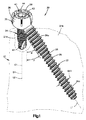
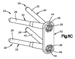
最初に図1を参照すると、アンカー・イン・アンカー固定システム20は、下にある構造体又は骨21に取り付けられて示されている。固定システム20は、第1の又は主骨固定要素又は骨アンカー22と、第1の骨アンカー22によって受け取られる第2の又は補助骨固定要素又は骨アンカー24とを含む一例示的実施形態による骨固定システムとして示されている。下の説明から明らかなように、骨固定システム20を使用して、創外固定器、内部骨固定デバイス、及び脊椎固定デバイスなどのような補助固定デバイスを下にある骨に確実に締結することができる。別に定めない限り、骨固定システム20及びその構成要素は、別に定めない限り、以下に限定されるわけではないが、チタン、TANのようなチタン合金、ステンレス鋼、強化プラスチック、及び同種移植骨などを含む当業技術で公知のあらゆる好ましい生体適合性材料から製造することができる。
Referring initially to FIG. 1, an anchor-in-
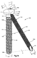
同様に図2A−Cを参照すると、第1の骨アンカー22は、中心縦軸L1に沿って縦方向に延びるシャフト26を含む。骨アンカー22は、それぞれ縦方向に相対する近位端又は上端、及び遠位端又は下端26a及び26b、並びに近位端26aに連結されたヘッド28を含む。螺旋状ネジ山30は、下にある骨と係合するように構成された近位端及び遠位端26a−bの及びこれらの間の位置でシャフト26から半径方向に延びる。従って、シャフト26の実質的に全体にネジ山を付けることができる。図1に示すように、ネジ山30は、遠位端26bから近位端26aに向う方向に増大する外径OD1を形成する。従って、近位端26aに配置されたネジ山30は、遠位端26bに配置されたネジ山30の外径よりも大きな外径を形成する。代替的に、図2A−Bに示すように、ネジ山30の外径OD1は、近位端及び遠位端26a−bにわたって一定である。従って、第1の骨アンカー22は、図示のようにロッキングスクリューとして設けることができることを認めるべきであるが、第1の骨アンカーは、代替的に、シャフトが必要に応じて滑らか又は波形である圧縮スクリュー、釘、リベット、又はピンとして設けることができることを認めるべきである。
Referring also to FIGS. 2A-C, the
ヘッド28は、半径方向内側表面33、対向する半径方向外側表面35、近位端又は上端28a、及び遠位端又は下端28bを形成する環状本体32を含む。環状本体32は、図示のような球状のセグメントの形状を形成することができ、近位端及び遠位端28a−bのいずれにおけるよりも近位端及び遠位端28a−b間の位置において大きな直径又は断面寸法を有する。従って、半径方向外側表面35は、球状又はそうでなければ凸面とすることができる。勿論、ヘッド28は、必要に応じてあらゆる他の好ましい代替の形状を取ることができる。
The
ヘッド28の遠位端28bは、シャフト26の近位端26aとヘッド28の遠位端28bと間に連結されたネジなしネック34を通じて直接又は間接のいずれかでシャフト26の近位端26aに連結される。環状本体32は、ヘッド28の周りで周方向に連続的に延びる遠位端28bでの基部37を含むことができる。環状本体32は、遠位端28bから上方に延びる複数の周方向に離間した保持タブ36を更に含む。従って、保持タブ36の末端は、ヘッド28の近位端28aに配置される。保持タブ36は、周方向に隣接するタブ36が、基部37に向うがこれを通過しない方向にヘッド28の近位端28a内に遠位に延びるスロット38によって分離されるように構成される。
The
ヘッド28は、中心ボア軸C1に沿って環状本体32を貫通して中心を延びるボア40を更に形成する。中心軸C1は、縦軸L1に対して角度的にオフセットされた方向に延びる。シャフト26は、基部37に連結され、シャフト26がボア40と干渉しないように基部37の半径方向外側表面35から半径方向外向き及び下方に延びる。ヘッド28は、タブ36と基部部分37とを含む環状本体32の半径方向内側表面33から半径方向内向きに延びるボア40における複数の螺旋状ネジ山41を含む。図示の実施形態において、ボア40の中心軸C1は、鋭角αを形成するようにシャフト26の縦軸L1と交差する。角度αは、鋭角であるように示されている。従って、一実施形態によると、角度は、0°から90°、例えば、20°から60°、例えば、20°から40°である。
The
図示の実施形態において、中心軸C1は、近位端及び遠位端28a−bに対して法線方向であるが、近位端及び遠位端28a−bは、中心軸C1が近位端及び遠位端28a−bの一方又は両方に対して非垂直角度を形成するように構成することができることを認めるべきである。従って、続いて図1−2Bを参照すると、第1の骨アンカー22のヘッド28は、近位端及び遠位端28a−bによって形成された中心ヘッド軸D1を定める。特に、中心軸D1は、近位端及び遠位端28a−bに対して法線の方向に延びる。ボア40の中心軸C1は、図示の実施形態では近位端及び遠位端28a−b間に延びる方向に対して平行に延びるので、軸C1及びD1は、縦方向に整列し、かつ実質的に一致し、従って、シャフト26の縦軸L1に対して同じ角度αを形成する。別に定めない限り、ヘッド28の向きは、シャフト26に対するボア40の角度オフセットに等しくシャフト26に対して角度的にオフセットされるが、軸C1及びD1が、代替的に、必要に応じて角度的にオフセットされる場合があることを認めるべきである。
In the illustrated embodiment, the central axis C1 is normal to the proximal and
内面33は、図2A−Bに示すようにボア40内に周方向に連続的に延びるネジ山41を含むことができるが、ヘッド28は、第2の骨アンカー24を中心ボア軸C1、ヘッド軸D1、及び縦軸L1に対して可変角度でヘッド28の内側に取り付けることを可能にする代替的な実施形態により構成することができることを認めるべきである。特に、図2Cに示すように、ヘッド28は、内面33内に延びる複数の凹部51を含むことができる。凹部51は、円筒体の一部分を形成することができ、従って、第2の骨アンカー24の対応する部分を受け取るように構成することができる。ネジ山41は、隣接する凹部51間に延びる。4つの凹部51は、互いに対して90°で周方向に等距離で離間するように示されているが、ヘッド28は、図4Dを参照して以下で説明するように、第2の骨アンカー24をあらゆる望ましい角度でヘッド28に挿入することを可能にするように、どのような数の凹部51も含むことができることを認めるべきである。
The
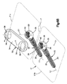
ここで図1及び3を参照すると、第2の骨アンカー24は、中心縦軸L2に沿って縦方向に延びるシャフト42を含む。シャフト42は、シャフト26の縦方向長さよりも長く、短く、又は実質的にこれに等しくすることができる。シャフト42は、それぞれ縦方向に対向する近位端又は上端、及び遠位端又は下端42a及び42bを定める。骨アンカー24は、シャフト42の近位端42aに連結されたヘッド44を含む。螺旋状ネジ山46は、下にある骨と係合するように構成された近位端及び遠位端42a−bの及びこれらの間の位置でシャフト42から半径方向に延びる。従って、シャフト42の実質的に全体にネジ山を付けることができる。ネジ山46は、図示のように近位端及び遠位端42a−bにわたって一定の外径OD2を形成するが、ネジ山46は、代替的に、骨アンカー22のシャフトに関して上述したように、遠位端42bから近位端42aに向う方向に増加する。外径OD2は、外径OD1よりも大きく、小さく、又は実質的にこれに等しくすることができる。ネジ山46は、第1の骨アンカー22のネジ山30に対して同じピッチ又は異なるピッチを形成することができる。
1 and 3, the
ヘッド44は、半径方向内側表面43、対向する半径方向外側表面45、近位端又は上端44a、及び遠位端又は下端44bを形成する環状本体48を含む。外面45は、軸C2の周りで同心に延び、かつヘッド44の遠位端44bから近位端44aに向う方向に増大する外径OD3又は断面寸法を有する図示のような錐台の形状を形成することができる。代替的に、ヘッドは、近位端及び遠位端44a−bのいずれにおけるよりも近位端及び遠位端44a−b間の位置において大きな直径又は断面寸法を有する図示の球状のセグメントのような必要に応じてあらゆる好ましい代替の形状を取ることができる。図示の実施形態において、中心軸C2は、シャフト42の縦軸L2と平行であり、かつこれと一致又は整列するが、中心軸C2は、必要に応じて縦軸L2から角度的にオフセットされる場合があることを認めるべきである。
The
ヘッド44の遠位端44bは、図示のように直接に又は第1の骨アンカー22に関して上述したタイプのネジなしネック39を通じて間接的にシャフト42の近位端42aに連結される。ヘッド44は、環状本体48の外面45から半径方向に延びる螺旋状ネジ山50を含む。従って、第2の骨アンカー24は、図示のようにロッキングスクリューとして設けることができることを認めるべきであるが、第2の骨アンカーは、代替的に、シャフトが必要に応じて滑らか又は波形である圧縮スクリュー、釘、リベット、又はピンとして設けることができることを認めるべきである。
The
ヘッド44は、近位端及び遠位端44a−bによって形成された中心軸D2を更に形成する。特に、中心軸D2は、近位端及び遠位端44a−bに対して法線の方向に延びる。中心軸C2のヘッド44は、図示の実施形態では近位端及び遠位端44a−b間に延びる方向に対して平行に延びるので、軸C2及びD2は、一致又は整列し、従って、図示の実施形態では縦方向L2と平行に延び、かつこれと一致又は整列する。勿論、近位端及び遠位端44a−bは、軸C2及びD2が互いに角度的にオフセットされるように幾何学的に構成することができることを認めるべきである。
The
ネジ山50は、ヘッド44の遠位端44bからヘッド44の近位端44aへの方向に増大する外径OD3を形成する。従って、ネジ山50の外径は、遠位端44におけるよりも近位端44aにおいて大きい。ボア40のネジ山41の内径は、ネジ山50及び41が嵌合するように構成されるように、遠位端bから近位端44aに向う方向に増大する内径を形成することができる。勿論、ネジ山50及び41の外径は、対応する近位端及び遠位端にわたって一定とすることができることを認めるべきである。
The
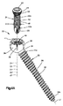
ここで、骨固定システムのアセンブリを図1及び4A−Cに関して説明する。特に、第1の骨アンカー22のボア40は、第1及び第2の骨アンカー22及び24が互いに締結されるように、第2の骨アンカー24を受け取るように構成される。従って、使用中に、外科医は、下にある骨21のターゲット区域にアクセスするように切開部を形成する。次に、第1の骨アンカー22は、ネジ山30が、下にある骨セグメント21a−bのうちの選択したものと係合してこれに骨アンカー22を取り付けるように、下にある骨21に押し込まれ、例えば、ねじ込まれる。骨アンカー22及び24のいずれか又は両方は、タッピンねじ式とすることができ、従って、切断縦溝25を含み、又は骨21へのシャフト26の挿入前に骨21にボアを事前にドリルで開けることができる。第1の骨アンカー22は、十分な深さまで骨セグメント21aのような下にあるセグメントに挿入され、ボア40の軸C1が、第2の骨セグメント21bのような第2の下にあるセグメントの望ましい固定位置と整列するまで回転する。第1の骨アンカー22が下にある骨に締結された状態で、第2の骨アンカー24は、第1の骨アンカー22のヘッド28を通して下にある骨21に挿入される。第2の骨アンカー24は、第1の骨アンカー22を受け取ったのと同じ切開部を通して又は必要に応じて第2の切開部通して、下にある骨21に挿入することができる。
The assembly of the bone fixation system will now be described with respect to FIGS. 1 and 4A-C. In particular, the
一実施形態において、第1の骨アンカー22は、必要に応じて大腿骨、上腕骨、脛骨、橈骨、尺骨、又はあらゆる他の骨のような長骨とすることができる下にある骨21の第1の骨折セグメント21aに締結され、第2の骨アンカー24は、下にある骨21の第2の骨折セグメント21bに締結される。例えば、第1の骨アンカー22は、患者の大腿骨のシャフト又は髄内部分に締結することができ、一方、第2の骨アンカー24は、患者の大腿骨の頭部に締結することができる。この点で、アンカー・イン・アンカー骨固定システム20を使用して大腿骨骨折部を固定することができるが、固定システム20及び固定システムを使用する手術方法は、外科医が1つ又はそれよりも多くの骨又は骨片を結合することを望む他の手術手順においても等しく適用可能である点を理解すべきである。
In one embodiment, the
続いて図1及び4A−Cを参照すると、ネジ山46の外径OD2は、シャフト42を図4Bに示すようにボア40を通して直線的に押し下げることができるように、第1の骨アンカー22のヘッド28を貫通して延びるボア40の内径よりも小さい。代替的に、外径OD2は、ネジ山46が、骨アンカー24がその中で回転するとヘッド28のネジ山41と係合することができるような大きさにすることができる。上述のように、ヘッド44の雄ネジ50は、ヘッド28の雌ネジ41と嵌合するように構成される。従って、第1の骨アンカー22のシャフト42は、シャフト42の遠位端42bが骨21と係合するか又はネジ山41及び50が係合するまでボア40を通過することができる。
With continued reference to FIGS. 1 and 4A-C, the outer diameter OD2 of the
骨アンカー22及び24は、次に、第1及び第2の骨アンカー22及び24が互いに固定されるように互いに対して回転し、縦方向にシャフト42を骨21内に進め、縦方向にシャフト42の前進と同じ速度で第1の骨アンカー22のヘッド28の内側のヘッド44を骨内に進めることができる。従って、第2の骨アンカー24は、第1の骨アンカー22を下にある骨21に対して圧縮することなく第1の骨アンカー22に取り付けることができる。代替的に、ヘッド28に対するヘッド44の係合が、第1の骨アンカー22を下にある骨22に対して圧縮させるように、ヘッド44は、ネジ山を欠くことができ、かつヘッド28の内面33は、ネジ山を欠くことができる。ヘッド44の半径方向内側表面43は、ヘッド28の内側のヘッド44を回転させるスクリュー駆動手段によって係合することができる六角形又はあらゆる代替的に成形された構造体を形成することができる。代替的に又は追加的に、第1の骨アンカー22が第2の骨アンカー24と共に回転するのを防止するツールを保持タブ36間に配置されたスロット38に挿入することができる。
The bone anchors 22 and 24 are then rotated relative to each other such that the first and second bone anchors 22 and 24 are secured to each other and advance the
一般的に、第2の骨アンカー24は、下にある骨21とネジ山41及び50の係合前に係合する。第2の骨アンカー24のヘッド44の遠位端44bが、第1の骨アンカー22のヘッド28の近位端28aと係合すると、保持タブ36は半径方向外向きに屈曲することができる。第1及び第2の骨アンカー22及び24が完全に嵌合した状態で、第2の骨アンカー24のヘッド44は、第1の骨アンカー22のヘッド28の内側で入れ子にされ、ヘッド44の近位端44aは、ヘッド28の近位端28aと実質的に同一平面にある。第1の骨アンカー22のシャフト26は、下にある骨21に対して斜めに延び、一方、第2の骨アンカーのシャフト42は、下にある骨21に対して実質的に法線方向に延びるが、両シャフトは、代替的に、下にある骨に対して斜めの方向に延びることができることを認めるべきである。
Generally, the
保持タブ36は、以下でより詳細に説明するように、骨プレート、髄内釘、又はスクリュー、椎間インプラント、及び椎弓根スクリューなどのような補助骨固定デバイスの開口にヘッド28をロックする時に特に有用性がある。ヘッド28は、代替的に、ヘッドの近位端及び遠位端28a−bで及びこれらの間で周方向に連続的とすることができることを認めるべきである。
このようにして、互いの内側にロックされると、骨アンカーは、縦軸L1及びL2によって形成された安定な三角形の耐加重平面Pと、シャフト24及び42間(例えば、シャフト24及び42の末端間)に延びる方向とを形成する。三角形の耐加重平面Pは、より強い力に耐えて骨内の骨アンカーの陥没又は移動をより良く防止することができる。すなわち、骨アンカー22及び24は、互いに対して傾斜するので、各骨アンカーは、例えば、下にある骨21から骨アンカーを引き出す傾向があると考えられる他の骨アンカーに印加された縦方向力によって骨内の移動に抵抗する。このようにして、アンカー・イン・アンカー骨固定システム20は、外科医が予想される負荷に耐えるように骨アンカー22及び24のような多数の骨アンカーを挿入することを可能にしながら、例えば、プレート、髄内釘又はスクリュー、及び椎間インプラントなどのようなより小さな補助固定デバイスを使用することを可能にする。
In this way, when locked inside each other, the bone anchor is between the stable triangular load-bearing plane P formed by the longitudinal axes L1 and L2 and the
ここで図4Dを参照すると、図2Cに示すヘッド28は、第2の縦軸L2が中心ボア軸C1、ヘッド軸D1、及び第1の縦軸L1に対して可変角度を形成するように、第2の骨アンカーをヘッド28に取り付けることを可能にする。特に、第2の骨アンカー24は、骨アンカー24の第1の部分が、凹部の1つに配置され、第1の部分に対して遠位にある骨アンカーの第2の部分が、骨アンカー24の第1の部分が配置された凹部に対向する凹部の別の1つに配置されるようにボア40に挿入することができる。図示の実施形態において、ヘッド44は、ヘッド軸D2及び従って縦軸L2が、ヘッド44の近位端が配置された凹部に対向する凹部の別の1つに向う方向の中心ボア軸C1に対して角度的にオフセットされるような位置においてヘッド44の近位端が凹部の1つに配置されるようにボア40に挿入される。ヘッド44は、中心軸C2、ヘッド軸D2、及び縦軸L2のいずれか1つ又は全てが、中心軸C1及びヘッド軸D1のいずれか一方又は両方に対して角度、例えば、0°から30°を形成するように、必要に応じて凹部51のいずれか1つに配置することができることを認めるべきである。
Referring now to FIG. 4D, the
ネジ山50のネジ山ピッチは、一端(例えば、近位端)から他端(例えば、遠位端)までアンカー24の中心軸に沿って測定された時にナロー・ツー・ワイド・ツー・ナローから変えることができる。このネジ山プロフィールは、開示全体を本明細書において示すかのようにここで本明細書に引用により組み込まれる2009年1月9日出願の米国特許出願出願番号第11/971,358号明細書で説明されているように、選択された角度に関係なく雌ネジ41との同程度の接触を維持しながら、アンカー24がある範囲の角度内の選択可能な角度でボア40と係合することを可能にする。すなわち、角度の許容可能範囲内の中心ボア軸C1に対するアンカー24の角度は、ネジ山41とネジ山50の係合に影響を及ぼさない。
The thread pitch of the
以下で説明するように、アンカー・イン・アンカー骨固定システムは、長骨適用、肩人工装具、脊椎用途に使用することができ、骨アンカーが直接に下にある骨セグメントに固定される独立型固定に使用することができ、又は骨プレート、髄内釘又はスクリュー、椎間インプラント、又は椎弓根スクリューのような他の脊椎インプラント、及び肩人工装具のような1つ又はそれよりも多くの補助固定デバイスを含むことができる。本明細書で説明するタイプのアンカー・イン・アンカー固定システムは、従って、2つ又はそれよりも多くの骨又はセグメントを固定するように長骨骨折部固定に使用することができ、小関節面の脊椎又は椎弓形成固定処置、及び肩人工装具に使用することができる。本明細書で説明するようなアンカー・イン・アンカーシステムのいずれに対しても、具体的に明記しない限り、特に特定した手順及び/又は用途に限定されることを意図していない点に注意すべきである。 As described below, the anchor-in-anchor bone fixation system can be used for long bone applications, shoulder prostheses, spinal applications, and is a stand-alone device where the bone anchor is fixed directly to the underlying bone segment One or more such as bone plates, intramedullary nails or screws, intervertebral implants, or other spinal implants such as pedicle screws, and shoulder prostheses An auxiliary fixation device can be included. An anchor-in-anchor fixation system of the type described herein can thus be used for long bone fracture fixation to fix two or more bones or segments, Can be used for spinal or laminoplasty fixation procedures and shoulder prostheses. Note that for any of the anchor-in-anchor systems as described herein, unless specifically stated otherwise, it is not intended to be limited to any particular procedure and / or application. Should.
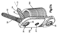
例えば、ここで図5及び6A−Fを参照すると、1つ又はそれよりも多くのアンカー・イン・アンカー骨固定システム20は、患者の身体に1つ又はそれよりも多くの長骨又は骨片を固定するように構成されたアンカー・イン・アンカー固定アセンブリ23を形成するように、骨プレート52のような補助固定デバイスと共に使用することができる。従って、固定アセンブリ23は、補助固定デバイスに連結するように構成された少なくとも1つの例えば複数のアンカー・イン・アンカー骨固定システムを含む。固定アセンブリ23の様々な実施形態が、固定システム20及び120の一方又は両方に対して示されているが、いずれか又は両方の固定システム20又は120は、別に定めない限り、補助固定デバイスに連結することができることを認めるべきである。固定アセンブリ及びその構成要素は、別に定めない限り、以下に限定されるわけではないが、チタン、TANのようなチタン合金、ステンレス鋼、強化プラスチック、及び同種移植骨などを含む当業技術で公知のあらゆる好ましい生体適合性材料から製造することができる。
For example, referring now to FIGS. 5 and 6A-F, one or more anchor-in-anchor
骨プレート52は、望ましいように構成することができ、内側骨向き面53及び対向する外面55を形成する細長平面プレート本体54を含む。複数の骨固定開口56(図示のような1対の開口56)のような1つ又はそれよりも多くのものは、プレート本体54の内面及び外面53及び55に対して垂直に延びる中心軸Aに沿ってプレート本体54を貫通して延びる。プレート本体54は、従って、開口56間に配置され、骨セグメント21a−bを分離する骨折部Fを覆うように構成される中心プレート部分57を形成する。プレート本体54は、図示のような平面とすることができるが、プレート本体54は、実施される骨固定のタイプに依存して下にある骨に部分的に又は完全に一致するように、湾曲するか又は望ましいように成形することができる。
The
開口56は、ヘッド28の外側半径方向面35の輪郭に適合する球状又はそうでなければ凸状内面58を呈する。複数の第1の骨アンカー22は、各ヘッド28が、対応する開口56に配置され、ボア40の中心軸C1が、対応する開口56の中心軸Aと一致し、シャフト26の縦軸L1が、開口56の軸Aに対して角度αを形成する方向にプレート52から下方に延びる。第2の骨アンカー24は、シャフト42が、軸Aに沿ってプレート52から下方に延びるように、上述の方式で第1の骨アンカー22に締結される。
The
ここで、下にある骨セグメント21a−bに骨プレート52を取り付ける方法を図6A−Eを参照して説明する。特に、第1の骨アンカー22は、骨セグメント21aに挿入され、第2の骨アンカー24は、骨セグメント21bに挿入される。骨セグメント21a−bは、骨折部Fの両側に配置することができる。第1の骨アンカー22は、ヘッド28を骨プレート52の開口56に挿入するように構成されるように、ある一定の角度で骨セグメント21a−bに挿入することができる。一実施形態によると、骨アンカー22は、ボア40の中心軸C1が、第2の骨アンカーが挿入すべき骨セグメントの表面に対して実質的に垂直に又は実質的に法線方向に向けられるまで、下にある骨セグメント21a−bの1つにおいて回転する。第2の骨アンカー24は、第1の骨アンカー22と同じ骨セグメント、又は骨折部によって第1の骨アンカー22の骨セグメントから分離された異なる骨セグメントに挿入することができる。ネジ山30は、骨アンカー22が直接に下にある骨セグメント21a−bに挿入されるようにタッピンねじ式とすることができる。代替的に、ガイドボアは、望ましい角度の向きで、下にある骨セグメント21a−b及び事前にドリルで穴を開けられたガイドボアに挿入された骨アンカー22にドリルで開けることができる。
A method of attaching the
骨アンカー22が、図6Aに示すように望ましい深さで下にある骨セグメント21a−bに挿入された状態で、外科医は、骨プレート52を事前に挿入された第1の骨アンカー22に作動的に連結することができる。特に、骨プレート52は、図6Bに示すように骨アンカー22の上に置かれ、開口56が対応するヘッド28を受け取るように骨アンカー22上に降ろされる。保持タブ36は、ヘッド28及び開口56の合わせ面が整列するまで半径方向内向きに圧縮され、それによって図6Cに示すように、骨アンカー22が下にある骨に固定された後に、プレート52が各骨アンカー22のヘッド28上に「スナップ留め」又は「クリック留め」されることを可能にする。この点で、外科医には、骨プレート52が骨アンカーヘッド28と嵌合した状態で触覚フィードバックがもたらされる。
With the
ヘッド28が開口56に配置された状態で、ヘッド28の球状又は凸状外面35及び開口56の合わせ内面は、骨アンカー22が骨プレート52に対して多軸的に回転することを可能にする。別に定めない限り、骨アンカー22は、第2の骨アンカー24がヘッド28のボア40を通過して下にある骨に入ることができる限り、あらゆる望ましい角度の向きで開口56に挿入することができる。第1の骨アンカー22は、必要に応じて骨セグメントに対してプレート52を圧縮するように下にある骨に挿入することができる。
With the
次に、図6Dを参照すると、第2の骨アンカー24は、それぞれの第1の骨アンカー22のヘッド28に挿入されてそれぞれの下にある骨セグメント21a−bに入る。特に、第1の骨アンカー22のシャフト42は、シャフト42の遠位端42bが骨21と係合するか又はネジ山41及び50が係合するかのいずれかまで直線的にボア40を通過する。第2の骨アンカー24のシャフト42は、骨プレート52に対して実質的に垂直の方向に延びることができることを認めるべきである。典型的には、シャフト42は、ネジ山41及び50が係合する前に下にある骨21と係合する。プレート本体54の垂直厚みは、プレート52がヘッド28に固定される時にシャフト26の近位端26aがプレート52と接続しないように、ヘッド28の垂直高さよりも小さい。
Referring now to FIG. 6D, the second bone anchors 24 are inserted into the
骨アンカー24は、次に、図6Eに示すように、第1及び第2の骨アンカー22及び24が互いにロックされるまで、ヘッド28から延びるネジ山50がヘッド44から延びるネジ山41と嵌合するように第2の骨アンカー24のシャフト42を骨21内に縦方向に進め、ヘッド44を第1の骨アンカー22のヘッド28の内側に縦方向に進めるように回転させることができる。従って、第1の骨アンカー22のシャフト26は、骨プレート52及び下にある骨21に対して斜めに延び、第2の骨アンカー24のシャフト42は、骨プレート52及び下にある骨21に対して垂直に延びるが、両シャフト26及び42は、代替的に、骨プレート52(及び下にある骨21)に対して斜めの方向に延びることができることを認めるべきである。
第2の骨アンカー24のヘッド44の遠位端44bが、第1の骨アンカー22のヘッド28の近位端28aと係合すると、保持タブ36は、開口56の内面58に対して半径方向外向きに屈曲し、それによってプレートに対して第1の骨アンカー22の位置を固定する摩擦嵌めを生じる。別に定めない限り、ヘッド28は、第2の骨アンカー24が第1の骨アンカー22と嵌合すると、骨プレート52に対して拡張する。特に、ヘッド44の外面45は、遠位端44bから近位端44aに向う方向に半径方向外向きにテーパ付きにすることができる。従って、ボア40内へかつこれを貫通する第2の骨アンカー24の挿入は、開口56の内面58に対して第1の骨アンカー22のヘッド28を半径方向に拡張させる。
When the
更に、上述のように、骨アンカーヘッド28の半径方向内側表面33及び骨アンカーヘッド44の半径方向外側表面45の両方は、第1の骨アンカー22が第2の骨アンカー24を受け取る時に互いに嵌合するように螺合され、それによって第2の骨アンカー24を第1の骨アンカー及び更に骨プレート52の両方に固定する。従って、使用時に、アンカー・イン・アンカー骨固定システム20は、拡張可能ヘッド28を有する第1の骨アンカー22と、骨プレート52に非平行な第2の骨アンカーをロックするロッキング圧縮スクリュー機構とを含む。従って、骨固定システム20は、各開口に単一の骨アンカーを受け取って骨プレートを下にある骨セグメントに固定する骨プレートに対してより高いレベルの安定性を達成することができるように、比較的小さなプレート区域に2つの非平行な骨アンカーの設置を可能にする。骨アンカーの1つ(図示のような第1の骨アンカー22)は、第2の骨アンカー24の垂直方向に対して角度的にオフセットされるので、そうでなければ骨21において移動させることができる第2の骨アンカーに印加された縦方向力は、第1の骨アンカー22のシャフト26に伝達され、これは、下にある骨21から骨アンカー24を引き抜く傾向があると考えられる縦方向力に抵抗する。
Further, as described above, both the radially
代替的に、骨プレート52は、骨セグメント21a−bに対して置くことができ、シャフト26は、シャフトを下にある骨に固定する前に開口56を通して挿入することができる。この代替的な実施形態において、骨アンカー20は、望ましい深さまで下にある骨に挿入され、プレート52は、ヘッド28に対して上げられる。保持タブ36を分離するスロット38が、ヘッド28の遠位部分28b内に有意に延びる場合、タブ36は、プレートがヘッド28の上に上げられると半径方向内向きに圧縮することができる。代替的に、ヘッド28は、1つの周方向外端(図7−8のスロット138を参照)だけにおいて分離される1対のタブ36を形成するように、ヘッド28を貫通して垂直に延びる単一スロット38を含むことができる。代替的に、第1の骨アンカー22のヘッド28の外面35は、開口56がヘッド28上に容易に適合するように実質的に直線的に、例えば、縦方向に延びることができる。ヘッド44がヘッド28の内側に固定されると、半径方向外側表面45は、上述の方式で骨プレート52に対して半径方向外向きに拡張し、それによって骨アンカー22及び24を骨プレート52に確実に締結する。
Alternatively, the
骨固定システム20及び骨固定アセンブリ23は、一実施形態により構成された第1及び第2の骨アンカー22及び24によって図示して説明しているが、骨固定システム及びアセンブリは、第1及び第2の骨アンカーが、下にある構造体、下にある構造体のセグメント、又は異なる構造体に接合するように、多数の代替的な実施形態により設けることができ、それによって第2の骨アンカーは、第1の骨のヘッドに形成されたボアを貫通して延びるように考えられている。
Although the
例えば、ここで図7A−Cを参照すると、アンカー・イン・アンカー固定システム120が示されており、それによって上述の固定システム20の同様の要素に対応する参照番号は、100ずつ増分させている。従って、固定システム120は、第1の又は主骨アンカー122と、第1の骨アンカー122のヘッド128に受け取られる第2の又は補助骨アンカー124とを含む。第2の骨アンカー124は、第2の骨アンカー24に関して上述したように構成され、一方、第1の骨アンカー122は、ヘッド128がシャフト126に対して平行に向くように構成される。
For example, referring now to FIGS. 7A-C, an anchor-in-
特に、シャフト126の近位端126aは、シャフト126が、ヘッド128に対して中心に配置されてヘッド128から縦方向に下方に延びるように、ヘッド128の遠位端128bに取り付けられる。従って、近位端及び遠位端128a−bに対して法線方向に延びる中心軸D1’は、シャフト26の縦軸L1に対して平行であってこれと一致している。勿論、シャフト126は、ヘッド128の中心軸D1からオフセットされる場合があることを認めるべきである。ボア140は、シャフト126の縦軸L1及びヘッド128の近位端及び遠位端128a−bに対して法線方向に延びる中心軸D1の両方に対して角度的にオフセットされた中心軸C1に沿ってヘッド128を貫通して延びる。特に、ボア140の中心軸C1は、縦軸L1及び中心軸D1’に対して鋭角αを形成する。従って、角度αは、40°から60°のような0°から90°である。ヘッド128は、骨アンカー22のヘッド28に関して上述したタイプの保持タブを含むことができ、又はヘッド128は、図7Aに示すように、近位端及び遠位端128a−bにおいて又はこれらの間で周方向に連続的とすることができる。
In particular, the
ここで図8Aを参照すると、固定システム120は、例えば、外傷性負荷の結果として起こったと考えられる長骨の「蝶形」骨折部固定処置において2つ又はそれよりも多くの骨片を互いに連結する独立型システムとして使用することができる。図示のように、第1の骨アンカー122のボア140は、第1及び第2の骨アンカー122及び124が互いに締結され、かつ下にある骨21に締結されるように、第2の骨アンカー124を受け取るように構成される。従って、使用中に、外科医は、下にある骨21のターゲット区域にアクセスするように切開部を形成する。次に、第1の骨アンカー122は、ネジ山130が下にある骨21と係合してこれに骨アンカーを取り付けるように、下にある骨21又は骨セグメント21aに押し込まれ、例えば、ねじ込まれる。
Referring now to FIG. 8A, the
第1の骨アンカー22は、十分な深さで骨セグメント21aのような下にあるセグメントに挿入され、ボア140の軸C1は、第2の骨セグメント21bのような第2の下にあるセグメントの望ましい挿入位置と整列するまで回転する。この点で、第1の骨セグメント122は、下にある骨21によって形成された平面に対して法線の方向の骨セグメント21aに挿入することができ、又は下にある骨21によって形成された平面に対して法線の方向に対して角度的にオフセットされた方向に挿入することができることを認めるべきである。
The
第1の骨アンカー122が、軸C1が第2の骨アンカー124に対するターゲット位置と整列するように下にある骨に締結された状態で、第2の骨アンカー124は、第1の骨アンカー122のヘッド128を通してセグメント21bのような下にある骨21に挿入される。第2の骨アンカー124は、第1の骨アンカー122を受け取ったのと同じ切開部を通して又は必要に応じて第2の切開部を通して、下にある骨21に挿入することができる。従って、第1の骨アンカー122は、例えば、断片化長骨セグメント21aに挿入することができ、一方、第2の骨アンカー124は、例えば、非断片化長骨セグメント21bに挿入することができ、それによって断片化骨セグメント21aを非断片化骨セグメント21bに固定する。図示のように、第1及び第2の骨アンカー122及び124各々のシャフト126及び142は、下にある骨21に対して斜めに延びるが、シャフトの一方は、代替的に、上述の方式で下にある骨に対して実質的に垂直に延びることができる。
With the
固定システム120は、浮動骨片を長骨に固定するために使用されるように図示して説明しているが、本明細書で説明するようなアンカー・イン・アンカー固定システムはまた、以下に限定されるわけではないが、頭蓋、顔、手、脚、及び骨盤などを含む身体の他の部分においても骨片を固定するのに使用することができることを認めるべきである。本明細書で説明するタイプのアンカー・イン・アンカー固定システムはまた、1つの断片を別の断片に(例えば、1つの骨片を別の骨片に)、又は1つの構造体を別の構造体に(例えば、1つの骨を別の骨に)固定するのに使用することができる。
Although the
アンカー・イン・アンカー骨固定システムは、外科医が予想される負荷に耐えるように骨アンカー122及び124のような多数の骨アンカーを挿入することを可能にしながら、例えば、プレート、髄内釘又はスクリュー、及び椎間インプラントなどのようなより小さな補助固定デバイスを使用することを可能にすることも認められるであろう。更に、互いの内側にロックされた時に、骨アンカーは、安定な三角形の耐加重平面Pを形成し、従って、より強い力に耐えて陥没又は移動をより良く防止することができる。すなわち、骨アンカー122及び124は、互いに対して曲げられるので、各骨アンカーは、例えば、下にある骨21から骨アンカーを引き抜く傾向があると考えられる他の骨アンカーに印加された縦方向力によって骨内の移動に抵抗する。
Anchor-in-anchor bone fixation systems allow, for example, plates, intramedullary nails or screws, while allowing a surgeon to insert multiple bone anchors such as bone anchors 122 and 124 to withstand the anticipated loads. It will also be appreciated that it is possible to use smaller auxiliary fixation devices such as intervertebral implants and the like. Furthermore, when locked inside each other, the bone anchors form a stable triangular load-bearing plane P and can therefore withstand stronger forces and better prevent collapse or movement. That is, since the bone anchors 122 and 124 are bent with respect to each other, each bone anchor is applied, for example, to a longitudinal force applied to other bone anchors that tend to pull the bone anchor away from the underlying
ここで図7A−C及び8B−Cを参照すると、アンカー・イン・アンカー固定アセンブリ23は、代替的に又は追加的に、一般的に骨固定システム20に関して上述した方式で患者の身体の1つ又はそれよりも多くの長骨又は骨片に固定するように構成された骨アンカー152のような補助固定デバイスと共に1つ又はそれよりも多くのアンカー・イン・アンカー骨固定システム120を含むことができる。特に、複数の第1の骨アンカー122は、各ヘッド128が対応する開口156に配置されるように骨プレート152に装着される。装着された時に、シャフト126は、縦軸L1が、対応する開口156の中心軸Aに対して実質的に平行であってこれと一致している方向に延び、かつボア140の中心軸C1が、中心軸Aに対して角度αを形成するように、プレート152から下方に延びる。すなわち、シャフト126は、従って、骨プレート152に対して実質的に垂直の方向に延びることを認めるべきであるが、シャフト126は、代替的に、骨プレート152に対して非垂直角度を形成することができることを認めるべきである。
Referring now to FIGS. 7A-C and 8B-C, the anchor-in-
第1の骨アンカー122が、中心軸C1が第2の骨アンカー124のターゲット位置と整列するように位置決めされた状態で、第2の骨アンカー124は、シャフト142が中心軸C1と一致した方向にプレート152から下方に延びて軸Aに対して角度αを形成するように、上述の方式で第1の骨アンカー122に締結される。図8B−Cに示すように、スロット138は、スロット138によって分離された1対の保持タブ136を形成するように、ヘッド128を貫通して垂直に延びる。従って、テーパ付きヘッド144は、上述の方式でヘッド128をプレート152に対してロックするように、ヘッド128を開口156の内面に対して半径方向外向きに屈曲させる。第1の骨アンカー122のシャフト126は、従って、骨プレート152及び下にある骨21に対して垂直に延び、第2の骨アンカー124のシャフト142は、骨プレート152及び下にある骨21に対して斜めに延びるが、両シャフト126及び142の両方は、骨プレート152及び下にある骨21に対して斜めに延びることができることを認めるべきである。
With the
代替的に、骨プレート152は、骨セグメント21a−bに対して置くことができ、シャフト126は、シャフトを下にある骨に固定する前に開口156を通して挿入することができる。この代替的な実施形態において、ヘッド128は、骨プレート152の開口156に降ろされる。ヘッド144がヘッド128に連結される時に、半径方向外側表面145は、上述の方式で骨プレート152に対して半径方向外向きに拡張し、それによって骨アンカー122及び124を骨プレート152に確実に締結する。
Alternatively, the
更に、骨アンカー22、24、122、及び124は、ネジ山がシャフトの全体に沿って、例えば、シャフトの近位端及び遠位端でかつこれらの間で延びる特に図示した実施形態により説明しているが、本明細書で説明する骨固定システムのいずれかと組み合わせて使用する骨アンカーは、代替方式で構成することができる。 Further, the bone anchors 22, 24, 122, and 124 are illustrated by the particularly illustrated embodiment in which the threads extend along the entire shaft, for example, at and between the proximal and distal ends of the shaft. However, bone anchors used in combination with any of the bone fixation systems described herein can be configured in an alternative manner.
例えば、図9A−Bを参照すると、第1の骨アンカー122は、上述の方式でシャフト126の全長に沿ってシャフト126から半径方向に延び、かつヘッド128から半径方向に延びる複数のネジ山130を含むように示されており、それによってロッキングスクリューをもたらす。ヘッド128から延びるネジ山130は、第1の骨アンカー122を骨プレート152に更に固定するように、開口156の内面158から半径方向に延びる相補的ネジ山183と係合するように構成される。従って、第1の骨アンカー122は、骨プレート152に螺合可能に連結され、第2の骨アンカー124は、第1の骨アンカー122に螺合可能に連結される。
For example, referring to FIGS. 9A-B, the
このようにして、第1の骨アンカー122は、下にある骨内にかつ開口156を通して挿入され、シャフト126は、ヘッド128から延びるネジ山130が、内面158においてネジ山と係合して骨アンカー122を骨プレート152に固定するように、開口156を通して最初に挿入される。この点で、ヘッド128とボア156の間のネジ式係合は、第2の骨アンカーヘッド144が、上述の方式で内面158に対してヘッド128を拡張する必要がないように、骨プレート152に対して骨アンカー122の角度位置を固定することを認めるべきである。更に、ヘッド128と骨プレート152の間のネジ式係合は、骨アンカー122及び124が、下にある骨に対してプレート152を圧縮することなく、下にある骨にプレート152を取り付けることを可能にする。
In this manner, the
骨プレート52は、固定システム20を通じて下にある骨21に取り付けられているように示されており、骨プレート152は、固定システム120を通じて下にある骨21に取り付けられるように図示して説明しているが、1つ又はそれよりも多くの固定システム20及び120は、骨プレート52及び152のいずれかを下にある骨21へ取り付けるために組み合わせて使用することができることを認めるべきである。
The
固定システム120が、独立型構成体(すなわち、補助固定デバイスなし)として設けられるか、又は固定アセンブリ23を設けるように骨プレート152のような補助固定デバイスと共に設けられるかに関わらず、第2の骨アンカー124と第1の骨アンカー122の間のネジ式係合は、ヘッド128の近位端128aが、薄型を提供し、かつ固定システム120に付随する外傷を最小にするように実質的に同一平面であるように、第2の骨アンカー124のヘッド144が第1の骨アンカー122のヘッド128内の皿頭であることを可能にする。
Regardless of whether the
代替的に、図10Aを参照すると、第1の骨アンカー122は、シャフト126に沿って単に部分的に延びるネジ山130を有するように設けることができる。図示のように、ネジ山130は、シャフト126の近位端126aが滑らかでネジ山を欠いているように、シャフトの遠位端126bから半径方向に延びる。骨アンカー122は、代替的に、周囲骨と係合して骨内の骨アンカー122の移動に抵抗する近位端126aから半径方向に延びる1つ又はそれよりも多くの固定リブを含むことができることを認めるべきである。第2の骨アンカー124は、シャフトの近位端142aがネジ山を欠いているように、シャフト142に沿って単に部分的に延び、特にシャフト142の遠位端142bから半径方向に延びるネジ山130を同様に呈することができることを更に認めるべきである。
Alternatively, referring to FIG. 10A, the
図10Bを参照すると、第1の骨アンカー22は、シャフト26に沿って単に部分的に延びるネジ山30を有するように設けることができる。図示のように、ネジ山30は、シャフト26の近位端26aが滑らかでネジ山を欠いているように、シャフト26の遠位端26bから半径方向に延びる。骨アンカー22は、代替的に、周囲骨と係合して骨内の骨アンカー22の移動に抵抗する近位端26aから半径方向に延びる1つ又はそれよりも多くの固定リブを含むことができることを認めるべきである。第2の骨アンカー24は、シャフトの近位端42aがネジ山を欠いているように、シャフト42に沿って単に部分的に延び、特にシャフト42の遠位端42bから半径方向に延びるネジ山46を同様に呈することができることを更に認めるべきである。ネジ山は、追加的に又は代替的に、上述の方式でヘッド28及び44から延びることができる。
Referring to FIG. 10B, the
代替的に、骨アンカー22、24、122、及び124の1つ又はそれよりも多くから全てにいたるまで、完全ネジ付きシャフト、部分的ネジ付きシャフト、又は全体にネジ山を欠いているシャフトを有するように構成することができることを認めるべきである。例えば、図11A−Cは、それらのシャフト26及び42が代替的な実施形態により構成された骨アンカー22及び24を含むような固定システム20の例示的実施形態を示すが、骨アンカー122及び124は、骨アンカー22及び24に対して図示して上述したように構成することもできる。
Alternatively, from one or more to all of the bone anchors 22, 24, 122, and 124, a fully threaded shaft, a partially threaded shaft, or a shaft that is entirely threadless. It should be appreciated that it can be configured to have. For example, FIGS. 11A-C illustrate an exemplary embodiment of the
例えば、図11Aを参照すると、第1の骨アンカー22のシャフト26は、図1に関して上述したようにその全体に沿って螺合されるが、第2の骨アンカー24のシャフト42は、ネジなし釘、リベット、又はネジなしピンを形成するためにネジ山を欠いている。そのようなネジなし骨アンカーの使用は、固定システム20又は120が海綿骨に固定のために埋め込まれる用途に特に有用である場合がある。ネジなし骨アンカー24は、シャフト42から半径方向に突出する1つ又はそれよりも多くのロッキング歯47を含むことができることを認めるべきである。歯47は、シャフト42の周りにスクリュー螺旋パターンを形成することができるが、同じく骨アンカー24を下にある骨に打ち込むことを可能にする。ヘッド44の半径方向外側表面45は、遠位端44bから近位端44aに向う方向に半径方向外向きに張り出す。従って、第1の骨アンカー22が、上述の方式で下にある骨に取り付けられると、第2の骨アンカー24のシャフト42は、第1の骨アンカーのヘッド28に挿入され、その後、下にある骨に打ち込まれる。ヘッド44がヘッド28に挿入される時に、外面45は、上述のようにプレート52に固定部材22をロックするように、保持タブ36を半径方向外向きに屈曲させる。
For example, referring to FIG. 11A, the
ここで図11Bを参照すると、第2の骨アンカー24のシャフト42は、図1に関して上述したようにその全体に沿って螺合されるが、第1の骨アンカー22のシャフト26は、ネジなし釘、リベット、又はネジなしピンを形成するためにネジ山を欠いている。シャフト26は、図11Aに示すように実質的に一定の直径を有することができ、又は外径は、シャフトの長さに沿って異なる場合がある。例えば、図示のように、シャフト26の近位端26aは、シャフト26aの遠位端26bにおける外径よりも大きな外径を形成する。ネジなし骨アンカー22は、シャフト26から半径方向に突出する1つ又はそれよりも多くのロッキング歯を含むことができることを認めるべきである。従って、第1の骨アンカー22は、下にある骨に打ち込むことができ、骨プレート52は、上述の方式で骨アンカー22のヘッド28に取り付けることができる。第2の骨アンカー24は、次に、下にある骨に挿入することができ、ヘッド44は、上述の方式で第1の骨アンカー22のヘッド28に取り付けることができる。
Referring now to FIG. 11B, the
更に代替的に、図11Cに示すように、両骨アンカー22及び24のシャフト26及び42は、ネジ山を欠くことができる。シャフト26及び42の一方又は両方は、これらの長さに沿って一定の外径を呈することができ、又はこれらの長さに沿って異なる外径を呈することができる。例えば、シャフト26の近位端26aは、シャフト26の遠位端26bの外径よりも大きな外径を呈する。手術中に、第1の骨アンカー22のシャフト26は、下にある骨に打ち込むことができ、骨プレート52は、上述の方式でヘッドに取り付けることができる。その後、第2の骨アンカー24のシャフト42は、図11Aを参照して上述した方式でヘッド44がヘッド28内で入れ子になるまで、ヘッド28を通して挿入して下にある骨に入ることができる。
Further alternatively, as shown in FIG. 11C, the
アンカー・イン・アンカー骨固定システム20及び120は、長骨固定するように構成された細長プレートと共に説明しているが、本明細書で説明するタイプのアンカー・イン・アンカー骨固定システムは、代替的に、あらゆる好ましい大きさ及び形状の骨プレートを含むことができることを認めるべきである。例えば、図12を参照すると、骨プレート252は、200ずつ増分された骨プレート52の同様の要素に対応する参照番号を有するように示されている。従って、プレート252は、下にある骨に対して平行に延びるように構成された第1の縦方向細長区画254aと、第1の細長区画254aの一端に配置されて第1の細長区画254aに対して垂直の方向に延びる横方向に細長い第2の区画254bとを有するプレート本体254を含む。従って、プレート252は、第2の細長区画254bが下にある長骨に対してほぼ垂直に延びるようにT字形である。プレート区画254a−bは、長骨に適合するように更に湾曲することができる。
Although the anchor-in-anchor
複数の縦方向に離間した開口256aは、第1のプレート区画254aを貫通して延び、複数の横方向に離間した開口256bは、第2のプレート区画254bを貫通して延びる。一実施形態において、T字形骨固定プレートは、複数の開口256aと複数の開口256bの間に縦方向に配置された骨折部を有する脛骨に取り付けられるように構成されるように考えられている。固定システム20及び120のいずれか又は両方は、開口256a−bの1つ又はそれよりも多くから全てにいたるまでそれに挿入することができる。図示のように、固定システム20は、骨プレート52に関して上述した方式で開口256a−bに挿入される。第1の骨アンカー22のシャフト26は、必要に応じてあらゆる角度方向に整列することができ、上にある骨セグメントを貫通し、骨折部を貫通して対向する骨折骨セグメント内に延びるように十分に長く構成することができることを認めることができる。
A plurality of vertically spaced openings 256a extend through the first plate section 254a, and a plurality of laterally spaced openings 256b extend through the
ここで図13A−Cを参照すると、アンカー・イン・アンカー固定アセンブリ23は、一方又は両方の固定システム20及び120、並びに長骨固定に使用するための髄内釘、スクリュー、又はロッド70(総称して本明細書では「ロッド」と呼ぶ)として設けられた補助固定デバイスを含むことができる。一般的に当業技術で理解されているように、髄内ロッド70は、固定すべき長骨の髄内管に挿入するように構成される。特に図13Aを参照すると、髄内ロッド70は、第1のセグメント72a及び第1のセグメント72aと同一の広がりを有する第2のセグメント72bを含む縦方向に延びる管状ロッド本体72を含む。第2のセグメント72bは、第1のセグメント72aの外径よりも大きな外径を形成するロッド本体72のヘッド部分として示されている。ロッドは、第1のロッドセグメント72bを貫通して延びる1つ又はそれよりも多くの第1の骨固定開口74aと、第2のロッドセグメント72bを貫通して延びる1つ又はそれよりも多くの第2の骨固定開口74bとを形成する。
Referring now to FIGS. 13A-C, the anchor-in-
開口74aは、ロッドセグメント72aの長さに沿って互いに縦方向に変位することができ、ロッドセグメント72aの円周の周りで更に互いに角度的に変位することができる。同様に、開口74bは、ロッドセグメント72bの長さに沿って縦方向に変位することができ、ロッドセグメント72bの円周の周りで更に互いに角度的に変位することができる。開口74a−bは、セグメント72a−bの直径と同一の広がりを有するロッド本体セグメント72a−bを貫通して中心を延び、又はセグメント72a−bの弦と同一の広がりを有するセグメント72a−bの中心からオフセットすることができる。開口74a−bはまた、所定の開口の一端が、開口の反対端に対して縦方向に変位するように、縦方向構成要素を形成することができる。ロッド70は、図示のように実質的に円筒形として示されているが、ロッド70は、必要に応じてあらゆる好ましい形状及び大きさを取ることができることを認めるべきである。
The openings 74a can be displaced longitudinally with respect to each other along the length of the
図13Bに示すように、アンカー・イン・アンカー骨固定システム120は、髄内ロッド70が周囲骨に取り付けられるように構成される。特に、骨アンカーの1つ、例えば、第1の骨アンカー122は、シャフト26を選択された開口74に挿入するように、例えば、ねじ込み、穿孔、及び打ち込みなどの機構を使用して開口74の選択された1つに押し込まれる。骨アンカーシャフト126は、対向する骨表面を通過することなくロッド70の内側で終端するか又はロッド72を貫通して延びるように長さを定めることができ、又はロッド72及び対向する骨表面の両方を通過するように十分な長さを定めることができる。シャフト126が、ボア140の中心軸C1が固定のために骨上のターゲット位置と整列するように望ましい回転位置で挿入される時に、第2の骨アンカー124は、同じく髄内ロッドに取り付けられることなく、第1の骨アンカー122に及び直接に髄内ロッド72を取り囲む骨に取り付けられる。勿論、第2の骨アンカー124も必要に応じて髄内ロッド72を貫通して延びる開口74に取り付けることができることを認めるべきである。
As shown in FIG. 13B, the anchor-in-anchor
図示の実施形態によると、シャフト142は、シャフト142を周囲骨21に挿入するように、例えば、ねじ込み、穿孔、及び打ち込みなどの機構を使用してボア140を通して挿入されて周囲骨21に押し込まれる。この点で、別に定めない限り、本明細書で説明するアンカー・イン・アンカー骨固定システムの全ての実施形態におけるように、骨アンカー122及び124のいずれか又は両方には、ネジ付きヘッド、ネジなしヘッド、ロッキングタブ136を含むヘッド又は近位端及び遠位端において及びこれらの間で周方向に連続的であるヘッド、完全ネジ付きシャフト、部分的ネジ付きシャフト、又は滑らかな半径方向外側表面を形成するか又は半径方向外側表面から突き出た歯47を含むネジなしシャフトを設けることができることを認めるべきである。
According to the illustrated embodiment, the
第1の骨アンカー122は、ロッド70に取り付けられるように構成され、第2の骨アンカー124は、周囲骨に取り付けられるように構成されるが、第2の骨アンカー124は、代替的に、上述の方式でロッド70に取り付けることができ、第1の骨アンカー122は、周囲骨に取り付けることができることを認めるべきである。この代替的な実施形態において、第1の骨アンカー22は、ボア140の中心軸C1が開口74の1つと整列するように骨21に押し込まれる。第2の骨アンカー124は、次に、シャフト142が整列した開口74を貫通して延び、かつこれに連結されるようにボア140を通して挿入される。
While the
第2の固定システム120は、上述の方式で髄内ロッド70及び周囲骨21に取り付けられるように示されているが、第1の固定システム20は、代替的に又は追加的に、髄内ロッド70及び周囲骨に取り付けることができることを更に認めるべきである。例えば、第1の骨アンカー22は、上述の方式で開口74の1つに取り付けることができ、第2の骨アンカーは、周囲骨21に取り付けることができ、又は第1の骨アンカー22は、上述の方式で周囲骨21に取り付けることができ、第1の骨アンカーは、開口74の1つに取り付けることができる。
Although the
ここで同じく図13Cを参照すると、髄内ロッド72は、骨折セグメント21a及び21bを形成する骨折長骨21の管49に挿入することができる。ロッド72は、骨折部Fが第1の開口74aと第2の開口74bの間に配置されるように管49に挿入される。固定システム120の1つ又はそれよりも多くは、上述の実施形態のいずれかにより、周囲骨21に取り付けられ、かつ1つの開口74a−bの1つ又はそれよりも多くから全てまでのそれに更に取り付けることができることを認めるべきである。代替的に又は追加的に、固定システム120の1つ又はそれよりも多くは、上述の実施形態のいずれかにより、周囲骨21に取り付けられ、かつ1つの開口74a−bの1つ又はそれよりも多くから全てまでのそれに更に取り付けることができる。
Referring again to FIG. 13C, the
従って、固定システム20及び120は、単独又は組み合わせて髄内ロッド72を周囲骨に締結するのに使用することができる。別に定めない限り、本明細書で説明する全ての実施形態において、固定システム20及び120は、独立型構成体として骨に直接に取り付ける時に、又は骨、骨代用品又は骨スペーサ、同種移植片、自家移植片、合成移植片、及び金属又はチタン移植片のような下にある構造体に補助固定デバイスを固定する時に組み合わせて使用することができることを更に認めるべきである。髄内ロッド72に取り付ける骨アンカーは、他の骨アンカーが、必要に応じてあらゆる角度の向きで周囲骨内に延びることができるように、あらゆる望ましい位置まで回転することができることを更に認めるべきである。
Accordingly, the
図13A−Cに図示の実施形態において、骨アンカーは、独立型構成体として髄内ロッド及び周囲骨21に直接に取り付けられ、骨アンカーは、いずれの付加的な補助固定デバイスによっても接合されない。しかし、アンカー・イン・アンカー固定アセンブリ23は、ここで図14A−Cを参照して以下でより詳細に説明するように、髄内ロッドのような第1の補助固定デバイスと共に使用することができる骨プレートのような第2の補助固定デバイスを更に含むことができることを認めるべきである。
In the embodiment illustrated in FIGS. 13A-C, the bone anchor is attached directly to the intramedullary rod and surrounding
ここで図14Aを参照すると、アンカー・イン・アンカー固定アセンブリ23は、代替的な実施形態により構成された髄内ロッド170に取り付けられた複数の骨固定システム20を含むように示されており、それによって上述の髄内ロッドの同様の要素に対応する参照番号は、100ずつ増分させている。髄内ロッド170は、その長さに沿って実質的に一定の外径を形成する管状ロッド本体172を含む。ロッド172は、ロッド本体172を貫通して延びる1つ又はそれよりも多くの開口174を形成する。ロッド172は、上述の方式で開口174が骨折部によって分離するように長骨の管に置かれるように構成される。図示のように、骨固定システム20は、開口174に取り付けられ、かつ上述の方式で周囲骨に取り付けられるように構成されるが、骨固定システム120は、本明細書で説明する方式で骨固定システム20と共に又は単独で髄内ロッド170を周囲骨に取り付けるのに使用することができることを認めるべきである。
Referring now to FIG. 14A, the anchor-in-
図14Bに示すように、アンカー・イン・アンカー固定アセンブリ23は、骨プレート52の形態の第2の補助骨固定デバイスを含むことができる。骨プレートは、望ましいように構成することができ、かつ上述の方式でプレート本体54とプレート本体54を貫通して延びて骨固定システム20に取り付けられるように構成された複数の開口5とを含む。骨プレート52は、骨折部が骨プレート52の開口56間に配置されるように、髄内ロッドにわたって延びる骨折部の上に置くことができる。例えば、第1の骨アンカー22は、髄内ロッド70に関して上述した方式で髄内ロッド170に取り付けられるように示されている。アンカー122のヘッド128は、上述の方式で骨プレート52の開口56の1つに挿入される保持タブを含む。従って、骨アンカー122は、骨プレート52及び髄内ロッド70の両方に取り付けられる。第2の骨アンカー124は、上述の方式で髄内ロッド170に取り付けることなく骨21に直接に取り付けることができる。
As shown in FIG. 14B, the anchor-in-
代替的に、第1の骨アンカー122のヘッド128は、上述の方式で骨プレート52に取り付けることができ、シャフト126は、髄内ロッド170を通過することなく骨21に取り付けることができること、並びに第2の骨アンカーは、ヘッド128を通過して髄内ロッド170の開口174の1つに取り付けることができることを認めるべきである。代替的に又は追加的に、骨固定システム20は、本明細書で説明する方式で骨固定システム120と共に又は単独で髄内ロッド170を骨プレート52及び周囲骨に取り付けるのに使用することができることを認めるべきである。髄内ロッド70又は必要に応じて構成されたあらゆる髄内ロッドは、骨固定システム20及び120単独の一方又は両方により、又は骨プレートのような第2の補助骨固定デバイスと共に周囲骨に取り付けることができることを更に認めるべきである。本明細書で説明するタイプの骨プレートには、必要に応じてあらゆる厚みを設けることができる。例えば、骨プレートは、例えば、腱、靭帯、及び筋肉のような軟組織構造体を締結して再位置決めするために、スクリューとして設けられる1対の骨アンカー間の縫合取り付けのための中間部材をもたらすように十分に薄く構成することができる。
Alternatively, the
図14A−Bに示すように、開口174は、開口がロッド本体172によって全ての側面上に形成されるように、ロッド本体172を貫通して延びることができることが認められる。代替的に又は追加的に、図14Cを参照すると、開口174は、ロッド本体172内に延びるノッチとして設けることができる。図示のように、ノッチ174は、断面がほぼ矩形であり、それに挿入される骨アンカーシャフトの外径と実質的に等しい厚みを有する。ノッチ174は、それを通して挿入される骨アンカーシャフト26の外径と実質的に等しいか又はこれよりも僅かに大きい深さでロッド本体172内に横方向に延びて終端する。ノッチ174は、従って、挿入シャフトとの摩擦嵌めをもたらすことができ、又は挿入シャフトと螺合可能に係合するように螺合することができる。
As shown in FIGS. 14A-B, it will be appreciated that the
ここで図15A−Bを参照すると、アンカー・イン・アンカー固定アセンブリ23は、200ずつ増分された髄内ロッド70の同様の要素に対応する参照番号を含むように示された釘270を含む。釘270は、例えば、橈骨遠位端の骨折部によって分離された1対の骨片に固定するように構成される。釘270は、中心部分272aの両方の縦方向外側の側面上に配置された釘本体272の残りの領域272bよりも大きな外径を有する中心部分272aを有する管状又は代替的に成形された釘本体272を含む。1つ又はそれよりも多くの縦方向に離間した開口274は、釘本体272の中心部分272a内に及びこれを貫通して延びる。各開口274には、釘本体272の内側の位置にある開口274から及び釘本体272の外面を貫通して延びるに関連する斜めの開口274aが設けられる。斜めの開口274aは、骨アンカー22及び24のシャフト26及び42間に形成された角度αに等しい関連する開口274の中心軸Aに対する角度を形成する中心軸Bに沿って延びる。各開口274には、固定柔軟性をもたらすように1対の斜めの開口274aを設けることができる。
Referring now to FIGS. 15A-B, the anchor-in-
固定システム20は、シャフト26が、開口274の近位端内に延び、次に、関連する補助開口274aの遠位端を通して誘導されるように、骨アンカー22を開口274に最初に挿入することによって釘270に挿入される。開口274は、アンカーヘッドが開口274内に収容されるように、アンカーヘッド28の外径と実質的に等しいか又はこれよりも僅かに大きな直径を形成することができる。補助固定デバイスのいずれも、受け取られた骨アンカーヘッドがその中に収容されるように構成された開口を含むことができることを認めるべきである。骨アンカー22が装着された状態で、第2の骨アンカー24は、上述の方式でアンカーヘッド22のボア40に挿入され、それによってヘッド22を開口274の内面に対して拡張させてロックさせる。特に、シャフト42は、アンカーヘッド28を貫通し、かつ開口274の遠位端を貫通して開口274の近位端内に延びる。このようにして、シャフト42は、下にある骨に対して実質的に法線方向に延び、一方、シャフト26は、下にある骨に対して斜めに延びる。開口274及び補助開口274aの遠位端は、必要に応じてそれぞれのシャフトの直径よりも広くすることができ、又は角度柔軟性をもたらすように細長スロットとして設けることができる。
The
ここで図16A−Cを全体的に参照すると、アンカー・イン・アンカー骨固定システムは、様々な固定処置によって図示して説明しているが、固定システムはまた、脊椎固定のために、例えば、骨折、変性疾患、及び腫瘍などから生じる例えば不安定性の管理のために、頸部及び/又は腰部後方小関節スクリュー固定において実施することができることが認識される。 Referring now generally to FIGS. 16A-C, an anchor-in-anchor bone fixation system is illustrated and described with various fixation procedures, but the fixation system can also be used for spinal fixation, for example, It will be appreciated that it can be performed in cervical and / or lumbar posterior small joint screw fixation, for example for management of instability resulting from fractures, degenerative diseases, tumors, and the like.
ここで図16A−Cを参照すると、本明細書で説明するタイプのアンカー・イン・アンカー固定アセンブリ23は、拡張可能骨プレート352として設けられた補助固定デバイスと、固定システム20として示す1対の固定システムとを含むことができる。骨プレート352が示されており、それによって骨プレート352の同様の要素に対応する参照番号は、100ずつ増分させている。従って、骨プレート352は、骨向き面353を形成する骨プレート本体354及び対向する表面355、並びにプレート本体354を貫通して延びる1対の開口356を含む。
Referring now to FIGS. 16A-C, an anchor-in-
骨プレート本体は、1対の本体セグメント363及び365を含む。本体セグメント363は、内側セグメントプレート263a及び外側セグメントプレート363b、並びにその中の本体セグメント365を受け取るような大きさにされるプレート363a−b間に配置された内部溝367を含む。溝367を形成する少なくとも一方又は両方の内面369は、それから延びて溝367に入る歯373を含む。同様に、本体セグメント365の表面の一方又は両方は、それから外向きに延びて歯373と係合するように構成された歯371を形成する。第1の本体セグメント363は、外側プレート363bに螺合されるネジ付きロッキング開口375を形成する。従って、ネジ付きロッキングピン377のシャフト377aは、内面353から外面355に向う方向に開口375を通して挿入することができ、ヘッド377bが互いに対してプレート363a−bを圧縮することができるように外側プレート363bのネジ山と係合し、それによって歯371及び373に係合させ、本体セグメント363及び365間の相対移動を阻止させる。
The bone plate body includes a pair of
手術中に、本体セグメント365は、溝367に挿入され、開口356がそれらの間に望ましい長さを定めるように延ばされるか又は後退する。第2の本体セグメント365は、セグメント365がロッキングピン377に干渉することなく摺ることを可能にする切り欠き379を含む。ロッキングピン377は、次に、開口375内に進んで本体セグメント365及び367の位置をロックするように開口375内で回転する。この点で、骨固定システム20は、骨アンカー22及び24のシャフト26及び42が上述の方式で下にある骨に挿入されるように、開口356内でロックすることができることを認めるべきである。固定システム20が、プレート352及び下にある骨に取り付けられた状態で、本体セグメント365は、下にある骨折部を復位し、又はそうでなければ互いの方向に固定システム20に接合された1対の骨又は骨片を圧縮するように溝367内で後退することができることを認めるべきである。代替的に、本体セグメント365は、固定システム20に接合された骨又は骨片を更に離間するように溝内に延びることができる。
During surgery, the
プレート352は、従って、上述の方式で骨折長骨に取り付けることができ、又は椎体切除術と組み合わせて使用することができ、それによって椎体は、脊椎インプラントによって置換される。例えば、ここで図17A−Dを参照すると、固定アセンブリ23は、脊椎インプラント300の形態の第2の固定部材と共に骨プレート352の形態の固定システム20及び補助固定デバイスを含む。インプラント300は、環状メッシュケージとして示されているが、あらゆる垂直インプラントを組み込むことができることを認めるべきである。図示のように、インプラント300は、固定システム間に配置され、従って、例えば、垂直体が取り外された後に椎間腔に挿入するように構成される。
The
インプラント300が椎間腔内に配置される時に、固定システム20は、例えば、前方接近を通じて頸椎領域において隣接する椎体Vに固定される。特に、両骨アンカー22及び24は、骨アンカーの1つがそれぞれの椎体Vを貫通して椎弓根Pの1つ内に延びるように椎体内に延びる。図示の実施形態によると、第1の骨アンカー22のシャフト26は、対応する椎体Vを通して椎弓根Pのうちのターゲットの1つに挿入される。各シャフト26が、椎弓根Pにおいてそのほぼ望ましい深さに到達した状態で、それは、中心軸C1が望ましい侵入角で椎体Vと整列するまで回転する。次に、骨固定プレート352は、プレート52に関して上述した方式でヘッド28に取り付けられる。例えば、開口356は、ヘッド28が開口356内に配置されるまでヘッド28の上に適合される。最後に、第2の骨アンカー24のシャフト42は、それぞれのヘッド28に及び対応する椎体Vに挿入される。シャフト42は、椎孔VF内に延びないような十分な長さを有する。
When the
必要に応じて、プレート352は、インプラント300が配置される椎間腔を定める隣接する椎体間の間隔を調節することが望ましい場合に、上述の方式で延ばすか又は圧縮することができる。この点で、固定システム23は、全ての骨アンカーが前方接近を通じて椎体Vに挿入されることを可能にすること、及び骨アンカー22及び24の角度オフセットは、上述の方式で三角形の耐加重平面を形成し、従って、後方接近を通じて付加的脊椎固定を必要とすることなく、より強い力に耐えて椎体内の骨アンカーの陥没又は移動をより良く防止することができることを認めるべきである。骨アンカー22は、図示のように垂直に整列した椎弓根Pに挿入することができ、又は第1の骨アンカー22の中心軸C1の角度の向きに依存して椎孔VFの両側に配置された椎弓根Pに挿入することができる。更に代替的に、1対の並列の開口は、1対の固定アセンブリ20が、それぞれの椎骨の両椎弓根内に延びる対応する対の骨アンカー24を含むように、骨プレート252の対向する縦方向端部に配置することができる。
If desired, the
ここで図18を参照すると、別の代替的な実施形態により構成された骨プレート452は、400ずつ増分された骨プレート52の同様の構造に対応する参照番号含むように示されている。従って、骨プレート452は、プレート本体454を含む。プレート本体454は、第1のセグメント454aと、円筒形であり従って、第1のセグメント454a内で回転可能である第2のセグメント454bとを含む。開口456のうちの1つは、第2のセグメント454bの回転軸に対して中心から外れた位置で第2のセグメント454bを貫通して延びる。別に定めない限り、第2のセグメント454bを貫通して延びる開口456は、偏心開口456に装着された骨アンカー22及び24の縦方向位置が調節可能であるように偏心して位置決めされる。
Referring now to FIG. 18, a
例えば、システム20のような第1の固定システムは、第1の骨アンカー22のシャフト26が骨プレート452に対して斜めの方向に延び、かつ第2の骨アンカー24のシャフト42がプレート452に対して実質的に法線方向に延びるように、上述の方式で第1のセグメント454aを貫通して延びる開口456内に固定されるが、両シャフト26及び42は、代替的に、骨プレート452に対して斜めの方向に延びることができることを認めるべきである。システム20のような第2の固定システムは、上述の方式で第2のセグメント454bを貫通して延びる開口456内に同様に固定される。従って、それぞれのシャフト24は、骨プレート452に対して斜めの方向に延び、かつシャフト42は、骨プレート452に対して実質的に法線方向に延びるが、両シャフト26及び42は、プレート452に対して斜めに延びることができる。固定アセンブリ20が開口456に固定される前又は後に、第2のセグメント454bは、第1のセグメント454aを貫通して延びる開口456に接合されたシャフト26及び42に対してそれぞれのシャフト26及び42の縦方向位置を調節するように、第1のセグメント454a内の矢印Rの方向に回転することができ、それによって固定アセンブリ20間の縦方向距離を増減する。
For example, a first fixation system, such as
固定システム20をプレート452に連結したように示されているが、本明細書で説明する全ての補助固定デバイスの場合のように、他の固定システム、この場合は第2の固定システム120を代替的に又は追加的にプレート452に連結することができると考えられることを認めるべきである。
Although the
ここで図19A−Cを参照すると、アンカー・イン・アンカー固定アセンブリ23は、椎弓根スクリューアセンブリ400として設けられた補助固定デバイスと共に骨固定システム120のような複数の骨固定システムを含むことができることを認めるべきである。椎弓根スクリューアセンブリ400は、固定ロッド404を通じて取り付けられた複数の椎弓根スクリュー402を含む。各椎弓根スクリュー402は、固定ロッド404を受け取るように構成された内部開口部408と、第1の骨アンカー122のヘッド128を受け取るように構成された下部開口部410とを含む。図示の実施形態によると、アンカー体406は、内部開口部408及び下部開口部410の両方を形成する。コレット412が、下部開口部410に対して圧縮するようにアンカー体406を囲み、キャップ414が、内部開口部408に対して圧縮するようにアンカー体406の上端に螺合的に挿入され、椎弓根スクリュー402において固定ロッド404をロックする。
Referring now to FIGS. 19A-C, anchor-in-
手術中に、第1の骨アンカー122のシャフト126は、下にある仙椎区域内にかつ椎弓根を通して椎体内に挿入され、又は代替的に椎弓根に対してオフセットされた位置にある第1の骨アンカー122を固定するように小関節面、薄膜、棘状突起、又は必要に応じて代替の脊椎構造体内に挿入することができる。骨アンカー122は、中心軸C1が椎弓根と整列するまで回転する。次に、第2の骨アンカー124のシャフト142は、ヘッド144が上述の方式でヘッド128に配置されるまで、ヘッド128を通して挿入され、かつ椎弓根に挿入される。下部開口部410は、次に、固定システム120を固定ロッド404に作動的に連結するようにヘッド128の上に適合される。シャフト126及び142の角度オフセットは、上述の方式で三角形の耐加重平面を形成し、従って、より強い力に耐えて椎体内の椎弓根スクリュー140の陥没又は移動をより良く防止することができる。図19Cに示すように、固定アセンブリ23は、必要に応じてあらゆる脊椎領域に配置することができる融合椎体の両方の対向する椎弓根上に装着された1対の椎弓根スクリューアセンブリ400を含む。
During surgery, the
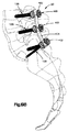
ここで図20A−Cを参照すると、アンカー・イン・アンカー固定アセンブリ23は、上腕骨インプラントと嵌合するように構成された肩人工装具500のようなインプラントとして設けられた補助固定デバイスに連結されたシステム120のような第1及び第2の骨アンカー・イン・アンカー固定システムを含む。人工装具500は、インサート504に連結された受け板502を含む。受け板は、チタンのようなインプラント等級金属から作ることができ、一方、インサート504は、ポリエチレンから作ることができる。
Referring now to FIGS. 20A-C, the anchor-in-
受け板502は、凹状インサート係合面508と対向する凸面510とを呈する受け板本体506を形成する。1対の離間した開口512は、それぞれの中心軸Aに沿って本体506を貫通して延びる。1対の円筒形延長部514は、開口512と整列した位置にある対向する表面510から下に突出し、各々が開口延長部512aを形成する。半径方向突起516は、各円筒形延長部の内面から内向きに延びて、インサート504を受け板502に固定するのに役立つ。リップ518が、各円筒形延長部514の遠位端から半径方向内向きに突出し、それぞれの固定システム120のための装着面を呈する。
The
固定システム120は、上述の方式で第1の骨アンカー122のシャフト126を下にある肩甲骨に最初に挿入することによって受け板502に及び下にある骨に取り付けられる。次に、第2の骨アンカー124のシャフト142は、上述の方式でヘッド144がヘッド128の内側に配置されるように、ヘッド128を通して下にある肩甲骨に挿入される。次に、受け板502は、リップ518が、それぞれのヘッド128の上でスナップしてそこにヘッド128をロックするように、ヘッド128の上に設けられる。シャフト126は、開口512の軸Aと整列することができ、かつシャフト142は、軸Aに対して角度を付けることができるが、両シャフト126及び142を軸Aに対して角度を付けることができると考えられることを認めるべきである。
The
インサート504は、人工の又は人工装具の関節窩をもたらすように凹面である支持面520と、対向する表面522とを形成する。1対のロッキングペグ524が、開口512と整列した位置で対向する表面522から下に突出する。ペグ524は、インサート504を受け板504に取り付けるように半径方向突起516受け取る周方向凹部526を形成し、その点で、人工関節窩520は、上腕骨インプラントのための関節表面を提供する。
The
支持面520の凹面は、上述のように人工の又は人工装具の関節窩を設けるのに適切であるが、支持面520は、必要に応じてあらゆる曲率で設けることができることを認めるべきである。例えば、支持面520の凹面は、例えば、股関節形成術において使用可能な球関節として使用可能な股関節臼蓋を設けるように構成することができる。 While the concave surface of the support surface 520 is suitable for providing an artificial or prosthetic glenoid fossa as described above, it should be appreciated that the support surface 520 can be provided with any curvature as required. For example, the concave surface of the support surface 520 can be configured to provide a hip acetabular cap that can be used, for example, as a ball joint that can be used in hip arthroplasty.
上述のような1つ又はそれよりも多くの骨固定アセンブリ23又はそれらの構成要素を含むキットを提供することができることを認めるべきである。キットの構成要素は、同じか又は異なるように構成することができる。例えば、骨アンカー22及び24は、シャフト42及び26の異なる長さ及び外径、外科医及び実施している手術手順の必要性に依存して個別に構成されたシャフト及びネジ山、並びにシャフトとヘッドの間に形成された異なる角度αを有するように提供することができる。キットは、上述のタイプの1つ又はそれよりも多くの補助固定デバイスを更に含むことができる。
It should be appreciated that a kit can be provided that includes one or more
本発明は、好ましい実施形態又は好ましい方法を参照して説明したが、本明細書で使用した単語は、制限する単語ではなく、説明及び例示の単語であることが理解される。例えば、本明細書で説明する様々な骨固定アセンブリ及びシステム、並びにこれらの構成要素の構造及び特徴は、別に定めない限り、本明細書で説明した他の骨固定アセンブリ及びシステム、並びにこれらの構成要素のいずれにも組み込むことができることを認めるべきである。更に、本発明は、特定の構造、方法、及び実施形態を参照して本明細書に説明したが、本発明は、本明細書で上述したような1つ又はそれよりも多くの骨固定システム、アセンブリ、又はこれらの構成要素を有するキットと共に本発明の範囲にある全ての構造、方法、及び使用にまで及ぶので、本発明は、本明細書に開示した事項に限定されることを意図していない。本明細書の教示の恩典を受ける当業者は、本明細書で上述したように本発明に対する多数の修正を達成することができ、例えば、特許請求の範囲に示すような本発明の範囲及び精神から逸脱することなく変更を加えることができる。 Although the present invention has been described with reference to preferred embodiments or preferred methods, it is understood that the words used herein are descriptive and exemplary words, not restrictive words. For example, the various bone fixation assemblies and systems described herein, as well as the structure and features of these components, unless otherwise specified, other bone fixation assemblies and systems described herein, and configurations thereof. It should be appreciated that it can be incorporated into any of the elements. Further, although the present invention has been described herein with reference to specific structures, methods and embodiments, the present invention is directed to one or more bone fixation systems as described herein above. The present invention is intended to be limited to the matters disclosed herein, as it extends to all structures, methods, and uses within the scope of the present invention, as well as assemblies or kits having these components. Not. Those skilled in the art who have the benefit of the teachings herein can accomplish many modifications to the invention as described hereinabove, for example, the scope and spirit of the invention as set forth in the claims. Changes can be made without departing from.
20 アンカー・イン・アンカー固定システム
22 第1の又は主骨固定要素又は骨アンカー
24 第2の又は補助骨固定要素又は骨アンカー
α シャフトの縦軸との交差角、鋭角
L1 中心縦軸
20 Anchor-in-
Claims (22)
少なくとも1つのアンカー・イン・アンカーシステムであって、
第1のシャフトと第1のヘッドを備えている第1の骨アンカーであって、前記第1のシャフトは第1の縦方向シャフト軸に沿って延び、前記第1のヘッドはボア軸に沿って貫通して延びるボアを形成し、前記ボア軸及び前記第1の縦方向シャフト軸が鋭角を形成する前記第1の骨アンカーと、
第2のシャフトと第2のヘッドを備えている第2の骨アンカーであって、前記第2のシャフトは第2の縦方向シャフト軸に沿って延び且つ下にある構造体に取り付けられるように構成され、前記第2の骨アンカーは前記ボア内に挿入されるように構成された前記第2の骨アンカーと、を有する前記少なくとも1つのアンカー・イン・アンカーシステムと、
骨管内に挿入するように構成された髄内釘であって、前記髄内釘は本体を有し、前記髄内釘は前記本体を通って延びる複数の開口を形成し、前記髄内釘が前記骨管内に配置されるとき、前記複数の開口のうちの1つが前記第1の骨アンカーの少なくとも1部分を受け取り、且つ前記アンカー・イン・アンカーシステムが前記髄内釘に連結されている、前記髄内釘と、
を有することを特徴とするアンカー・イン・アンカー固定アセンブリ。 An anchor-in-anchor assembly,
And at least one anchor-in-anchor system,
A first bone anchor comprising a first shaft and a first head, wherein the first shaft extends along a first longitudinal shaft axis and the first head is along a bore axis. The first bone anchor forming a bore extending therethrough, wherein the bore axis and the first longitudinal shaft axis form an acute angle;
A second bone anchor comprising a second shaft and a second head, said second shaft extending along a second longitudinal shaft axis and attached to an underlying structure The at least one anchor-in-anchor system comprising: the second bone anchor configured to be inserted into the bore; and
An intramedullary nail configured for insertion into a bone canal, the intramedullary nail having a body, the intramedullary nail forming a plurality of openings extending through the body, wherein the intramedullary nail is when disposed in the bone canal, said one of the plurality of openings is receiving at least a portion of the first bone anchor and said anchor-in anchoring system is connected to the intramedullary nail, The intramedullary nail;
An anchor-in-anchor fixing assembly comprising:
Applications Claiming Priority (3)
| Application Number | Priority Date | Filing Date | Title |
|---|---|---|---|
| US12013808P | 2008-12-05 | 2008-12-05 | |
| US61/120,138 | 2008-12-05 | ||
| PCT/US2009/066774 WO2010065855A1 (en) | 2008-12-05 | 2009-12-04 | Anchor-in-anchor system for use in bone fixation |
Related Child Applications (1)
| Application Number | Title | Priority Date | Filing Date |
|---|---|---|---|
| JP2015043709A Division JP6073397B2 (en) | 2008-12-05 | 2015-03-05 | Anchor-in-anchor system for use in bone fixation |
Publications (3)
| Publication Number | Publication Date |
|---|---|
| JP2012510875A JP2012510875A (en) | 2012-05-17 |
| JP2012510875A5 JP2012510875A5 (en) | 2013-01-31 |
| JP5759900B2 true JP5759900B2 (en) | 2015-08-05 |
Family
ID=41665215
Family Applications (3)
| Application Number | Title | Priority Date | Filing Date |
|---|---|---|---|
| JP2011539738A Active JP5759900B2 (en) | 2008-12-05 | 2009-12-04 | Anchor-in-anchor system for use in bone fixation |
| JP2015043709A Active JP6073397B2 (en) | 2008-12-05 | 2015-03-05 | Anchor-in-anchor system for use in bone fixation |
| JP2016134809A Active JP6290984B2 (en) | 2008-12-05 | 2016-07-07 | Anchor-in-anchor system for use in bone fixation |
Family Applications After (2)
| Application Number | Title | Priority Date | Filing Date |
|---|---|---|---|
| JP2015043709A Active JP6073397B2 (en) | 2008-12-05 | 2015-03-05 | Anchor-in-anchor system for use in bone fixation |
| JP2016134809A Active JP6290984B2 (en) | 2008-12-05 | 2016-07-07 | Anchor-in-anchor system for use in bone fixation |
Country Status (8)
| Country | Link |
|---|---|
| US (2) | US8591513B2 (en) |
| EP (2) | EP2385800B1 (en) |
| JP (3) | JP5759900B2 (en) |
| KR (1) | KR101709357B1 (en) |
| CN (1) | CN102292043B (en) |
| BR (1) | BRPI0922786A2 (en) |
| CA (1) | CA2745264A1 (en) |
| WO (1) | WO2010065855A1 (en) |
Families Citing this family (81)
| Publication number | Priority date | Publication date | Assignee | Title |
|---|---|---|---|---|
| US7722620B2 (en) | 2004-12-06 | 2010-05-25 | Dfine, Inc. | Bone treatment systems and methods |
| US9597118B2 (en) * | 2007-07-20 | 2017-03-21 | Dfine, Inc. | Bone anchor apparatus and method |
| WO2009091811A1 (en) | 2008-01-14 | 2009-07-23 | Brenzel Michael P | Apparatus and methods for fracture repair |
| JP5788787B2 (en) | 2008-03-26 | 2015-10-07 | ジンテス ゲゼルシャフト ミット ベシュレンクテル ハフツング | Universal fixing device for attaching objects to bone tissue |
| US8882838B2 (en) * | 2008-06-05 | 2014-11-11 | DePuy Synthes Products, LLC | Articulating disc implant |
| CN102046111A (en) | 2008-06-05 | 2011-05-04 | 斯恩蒂斯有限公司 | Articulating disc implant |
| US9289220B2 (en) * | 2008-06-24 | 2016-03-22 | Extremity Medical Llc | Intramedullary fixation assembly and method of use |
| US9044282B2 (en) * | 2008-06-24 | 2015-06-02 | Extremity Medical Llc | Intraosseous intramedullary fixation assembly and method of use |
| BRPI0922786A2 (en) | 2008-12-05 | 2019-09-24 | Synthes Gmbh | anchor-in-anchor systems for use in bone fixation |
| US9060808B2 (en) | 2008-12-05 | 2015-06-23 | DePuy Synthes Products, Inc. | Anchor-in-anchor system for use in bone fixation |
| JP5580403B2 (en) * | 2009-04-23 | 2014-08-27 | ジンテス ゲゼルシャフト ミット ベシュレンクテル ハフツング | Applicable bone fixation plate |
| US8709053B2 (en) * | 2009-04-30 | 2014-04-29 | Sean Suh | Orthopedic fastener blocking system |
| US8926611B2 (en) * | 2009-09-14 | 2015-01-06 | Zimmer Gmbh | Angular lag implant for intramedullary nails |
| US9381045B2 (en) | 2010-01-13 | 2016-07-05 | Jcbd, Llc | Sacroiliac joint implant and sacroiliac joint instrument for fusing a sacroiliac joint |
| US9333090B2 (en) | 2010-01-13 | 2016-05-10 | Jcbd, Llc | Systems for and methods of fusing a sacroiliac joint |
| US9757154B2 (en) * | 2010-01-13 | 2017-09-12 | Jcbd, Llc | Systems and methods for fusing a sacroiliac joint and anchoring an orthopedic appliance |
| WO2011088172A1 (en) | 2010-01-15 | 2011-07-21 | Brenzel Michael P | Rotary-rigid orthopaedic rod |
| CN102821707B (en) | 2010-01-20 | 2016-02-03 | 康文图斯整形外科公司 | For bone close to the device and method with bone cavity preparation |
| US8906022B2 (en) | 2010-03-08 | 2014-12-09 | Conventus Orthopaedics, Inc. | Apparatus and methods for securing a bone implant |
| JP5784710B2 (en) * | 2010-05-13 | 2015-09-24 | シンセス ゲゼルシャフト ミット ベシュレンクテル ハフツングSynthes Gmbh | Bone screw assembly and implantable device |
| US8961573B2 (en) | 2010-10-05 | 2015-02-24 | Toby Orthopaedics, Inc. | System and method for facilitating repair and reattachment of comminuted bone portions |
| CN101947139B (en) * | 2010-10-21 | 2013-10-23 | 赵大国 | Bionic dental implant and abutment and seminal root thereof |
| US8870963B2 (en) | 2010-10-27 | 2014-10-28 | Toby Orthopaedics, Inc. | System and method for fracture replacement of comminuted bone fractures or portions thereof adjacent bone joints |
| US11701238B2 (en) | 2011-01-06 | 2023-07-18 | Darren L. BERGEY | Compressive, orthopedic, anchoring apparatus and method |
| WO2012094647A2 (en) | 2011-01-06 | 2012-07-12 | Bergey Darren L | Interbody vertebral prosthetic device with blade anchor |
| JP2014511217A (en) * | 2011-02-02 | 2014-05-15 | ミッド コーポレーション | System, apparatus and method for implanting an implant |
| WO2012112495A1 (en) * | 2011-02-14 | 2012-08-23 | Synthes Usa, Llc | Intramedullary nail having self-retaining compression slot |
| US9254154B2 (en) | 2011-03-03 | 2016-02-09 | Toby Orthopaedic, Inc. | Anterior lesser tuberosity fixed angle fixation device and method of use associated therewith |
| AU2012253734B2 (en) | 2011-05-10 | 2016-07-14 | Synthes Gmbh | Facet interference cage |
| US8771324B2 (en) * | 2011-05-27 | 2014-07-08 | Globus Medical, Inc. | Securing fasteners |
| US9173683B2 (en) * | 2011-08-31 | 2015-11-03 | DePuy Synthes Products, Inc. | Revisable orthopedic anchor and methods of use |
| US9730797B2 (en) | 2011-10-27 | 2017-08-15 | Toby Orthopaedics, Inc. | Bone joint replacement and repair assembly and method of repairing and replacing a bone joint |
| US9271772B2 (en) | 2011-10-27 | 2016-03-01 | Toby Orthopaedics, Inc. | System and method for fracture replacement of comminuted bone fractures or portions thereof adjacent bone joints |
| US9402667B2 (en) * | 2011-11-09 | 2016-08-02 | Eduardo Gonzalez-Hernandez | Apparatus and method for use of the apparatus for fracture fixation of the distal humerus |
| EP3441029B1 (en) * | 2011-11-18 | 2020-06-03 | Synthes GmbH | Femoral neck fracture implant |
| WO2013082576A1 (en) * | 2011-12-01 | 2013-06-06 | Eminent Spine Llc | Bone screw |
| CN102715945A (en) * | 2012-06-08 | 2012-10-10 | 浙江科惠医疗器械有限公司 | Corner locking hollow screw for fracture treatment |
| KR102183765B1 (en) * | 2012-08-22 | 2020-11-30 | 신세스 게엠바하 | Anchor-in-anchor system |
| CN103654934B (en) * | 2012-08-30 | 2016-03-30 | 上海微创骨科医疗科技有限公司 | For blade plate combined locking screw and comprise its bone plate system |
| US10278742B2 (en) | 2012-11-12 | 2019-05-07 | DePuy Synthes Products, Inc. | Interbody interference implant and instrumentation |
| EP2740424B1 (en) * | 2012-12-10 | 2015-10-14 | Biedermann Technologies GmbH & Co. KG | Anchoring member suitable for use in a polyaxial bone anchoring device and polyaxial bone anchoring device with an enlarged pivot angle to one side |
| US9283008B2 (en) | 2012-12-17 | 2016-03-15 | Toby Orthopaedics, Inc. | Bone plate for plate osteosynthesis and method for use thereof |
| US10070969B2 (en) * | 2013-01-17 | 2018-09-11 | Stryker European Holdings I, Llc | Annulus plug for intervertebral disc repair |
| US10433880B2 (en) | 2013-03-15 | 2019-10-08 | Jcbd, Llc | Systems and methods for fusing a sacroiliac joint and anchoring an orthopedic appliance |
| EP2873384B1 (en) | 2013-11-14 | 2016-10-05 | Biedermann Technologies GmbH & Co. KG | Bone anchor and bone anchoring assembly comprising the same |
| AU2014362251B2 (en) | 2013-12-12 | 2019-10-10 | Conventus Orthopaedics, Inc. | Tissue displacement tools and methods |
| KR101624614B1 (en) | 2014-07-18 | 2016-05-27 | 주식회사 케이씨스 | Shrinkage or expansion possible functional intramedullary fixation apparatus |
| IN2014MU02601A (en) * | 2014-08-12 | 2015-10-23 | Dr Nitesh Kumar TANDIYA | |
| US10130487B2 (en) * | 2014-08-22 | 2018-11-20 | Globus Medical, Inc. | Vertebral implants and related methods of use |
| AU2015317308B2 (en) | 2014-09-19 | 2020-06-04 | Duet Spine Holdings, Llc | Single level fusion systems and methods of assembly and use |
| AU2015317306B2 (en) | 2014-09-19 | 2020-06-04 | Spine Forward, Llc | Fusion systems and methods of assembly and use |
| WO2016065489A1 (en) | 2014-10-31 | 2016-05-06 | RIOS Medical AG | Implant assembly for the sacroiliac joint |
| TW201617039A (en) * | 2014-11-06 | 2016-05-16 | 愛派司生技股份有限公司 | A bone screw for cable penetration |
| US9649133B2 (en) * | 2014-11-11 | 2017-05-16 | Intrepid Orthopedics | Supplemental fixation screw |
| KR101609581B1 (en) | 2015-10-19 | 2016-04-06 | (주)엘앤케이바이오메드 | Surgical screw and fusion device using thereof |
| KR101609582B1 (en) * | 2015-10-19 | 2016-04-06 | (주)엘앤케이바이오메드 | Surgical screw and fusion device using thereof |
| US10251685B2 (en) * | 2016-03-17 | 2019-04-09 | Stryker European Holdings I, Llc | Floating locking insert |
| US9962192B2 (en) | 2016-03-17 | 2018-05-08 | Medos International Sarl | Multipoint fixation implants |
| KR101907489B1 (en) * | 2016-08-31 | 2018-10-12 | 이모세 | Bone screw for orthopedic surgery |
| US11045242B2 (en) | 2016-09-22 | 2021-06-29 | Globus Medical, Inc. | Systems and methods for intramedullary nail implantation |
| US10492803B2 (en) | 2016-09-22 | 2019-12-03 | Globus Medical, Inc. | Systems and methods for intramedullary nail implantation |
| US10751096B2 (en) | 2016-09-22 | 2020-08-25 | Bala Sundararajan | Systems and methods for intramedullary nail implantation |
| US11083503B2 (en) | 2016-09-22 | 2021-08-10 | Globus Medical, Inc. | Systems and methods for intramedullary nail implantation |
| US10299847B2 (en) | 2016-09-22 | 2019-05-28 | Globus Medical, Inc. | Systems and methods for intramedullary nail implantation |
| US10918426B2 (en) | 2017-07-04 | 2021-02-16 | Conventus Orthopaedics, Inc. | Apparatus and methods for treatment of a bone |
| US10603055B2 (en) | 2017-09-15 | 2020-03-31 | Jcbd, Llc | Systems for and methods of preparing and fusing a sacroiliac joint |
| NL2020144B1 (en) * | 2017-12-21 | 2019-07-01 | Atro Medical B V | Orthopaedic implant and fixation system |
| US11446061B2 (en) * | 2018-02-05 | 2022-09-20 | Bespa Global, Llc | Implants and methods for treating charcot foot and other conditions |
| US10898232B2 (en) | 2018-03-20 | 2021-01-26 | Medos International Sàrl | Multipoint fixation implants and related methods |
| JP6960055B2 (en) * | 2018-06-12 | 2021-11-05 | オリンパステルモバイオマテリアル株式会社 | Bone surgical instruments |
| KR102553035B1 (en) | 2018-06-12 | 2023-07-07 | 올림푸스 테루모 바이오머티리얼 가부시키가이샤 | Goal Plates and Goal Plate Kits |
| US11266453B2 (en) * | 2018-09-21 | 2022-03-08 | DePuy Synthes Products, Inc. | Bone compression screws and related systems and methods |
| WO2020129019A2 (en) * | 2018-12-21 | 2020-06-25 | Azurmeds Inc | Instrumental system for a latarjet procedure and corresponding method |
| AU2019418411B2 (en) * | 2019-01-02 | 2023-03-16 | Orthofix Us Llc | Bone fixation system and methods of use |
| US11633219B2 (en) | 2019-06-26 | 2023-04-25 | Globus Medical, Inc. | Fenestrated pedicle nail |
| EP4013321A4 (en) * | 2019-08-14 | 2023-02-08 | K2M, Inc. | Pedicle fixation system |
| US11426210B2 (en) | 2019-09-25 | 2022-08-30 | Medos International Sàrl | Multipoint angled fixation implants for multiple screws and related methods |
| USD912821S1 (en) | 2020-01-14 | 2021-03-09 | Duet Spine Holdings, Llc | Halo screw implant |
| AU2021220225A1 (en) | 2020-02-14 | 2022-10-06 | Medos International Sarl | Integrated multipoint fixation screw |
| US20220192720A1 (en) * | 2020-12-18 | 2022-06-23 | DePuy Synthes Products, Inc. | Screw-in-screw bone fixation system |
| US11154330B1 (en) * | 2021-03-10 | 2021-10-26 | Chang Gung University | Dual-trajectory pedicle screw system for improvement of fixation stability |
Family Cites Families (101)
| Publication number | Priority date | Publication date | Assignee | Title |
|---|---|---|---|---|
| US611637A (en) * | 1898-10-04 | Box-fastening device | ||
| US928997A (en) * | 1908-07-07 | 1909-07-27 | Emanuel Mueller | Lock-screw. |
| US3474537A (en) * | 1965-10-19 | 1969-10-28 | Robert W Christensen | Dental prosthetic appliance |
| JPS54118566U (en) * | 1978-02-07 | 1979-08-20 | ||
| JPS54118566A (en) | 1978-03-06 | 1979-09-14 | Nippon Electric Co | Method of producing laminated ceramic capacitor |
| US4338835A (en) * | 1980-01-24 | 1982-07-13 | Leon Simons | Recessed head fastener and driver therefor |
| DE3124059A1 (en) * | 1981-06-18 | 1983-01-05 | Mecron Medizinische Produkte Gmbh, 1000 Berlin | Nail for fixing fractures of the femur |
| ATE44871T1 (en) * | 1984-09-04 | 1989-08-15 | Univ Berlin Humboldt | DISC PROSTHESIS. |
| US4828562A (en) | 1988-02-04 | 1989-05-09 | Pfizer Hospital Products Group, Inc. | Anterior cruciate ligament prosthesis |
| US5038978A (en) * | 1989-11-13 | 1991-08-13 | B&G Plastics, Inc. | Hanger and display support combined therewith |
| US5140877A (en) * | 1990-12-14 | 1992-08-25 | John Sloan | Hexagonal wrench |
| US5797918A (en) | 1991-12-13 | 1998-08-25 | David A. McGuire | Flexible surgical screwdriver and methods of arthroscopic ligament reconstruction |
| US5251521A (en) | 1992-01-31 | 1993-10-12 | Bondhus Corporation | TORX-compatible elliptical driver |
| US5207529A (en) * | 1992-06-29 | 1993-05-04 | General Motors Corporation | Fastening device |
| ATE197665T1 (en) * | 1992-11-02 | 2000-12-15 | Sulzer Orthopaedie Ag | ANCHORING FOR AN ARTIFICIAL BAND |
| FR2709412B1 (en) * | 1993-09-01 | 1995-11-24 | Tornier Sa | Screw for lumbo-sacral fixator. |
| US5443469A (en) * | 1994-05-02 | 1995-08-22 | Smith; Aubrey L. | Intramedullary reaming tissue protection guard |
| GB9411693D0 (en) * | 1994-06-10 | 1994-08-03 | Matthews Michael G | Surgical intramedullary nail for stabilisation of condylar and supracondylar fractures |
| US5976139A (en) * | 1996-07-17 | 1999-11-02 | Bramlet; Dale G. | Surgical fastener assembly |
| AU1997797A (en) * | 1996-05-31 | 1997-12-04 | Acromed Corporation | An apparatus comprising a plate and a fastener for connecting the plate to a bone portion |
| US5993463A (en) * | 1997-05-15 | 1999-11-30 | Regents Of The University Of Minnesota | Remote actuation of trajectory guide |
| IL133244A0 (en) * | 1997-06-02 | 2001-04-30 | Martello Jeannette | Soft tissue securing anchor |
| US5984681A (en) * | 1997-09-02 | 1999-11-16 | Huang; Barney K. | Dental implant and method of implanting |
| ATE245948T1 (en) * | 1997-10-20 | 2003-08-15 | Synthes Ag | BONE FIXATION DEVICE |
| SE510973C2 (en) | 1998-03-16 | 1999-07-19 | Scandimed International Ab | Instruments for repositioning and fixation of wrist fractures |
| US6013078A (en) * | 1998-08-19 | 2000-01-11 | Lin; Chin | Securing device for bone fastener |
| US6113637A (en) | 1998-10-22 | 2000-09-05 | Sofamor Danek Holdings, Inc. | Artificial intervertebral joint permitting translational and rotational motion |
| JP4167398B2 (en) | 1998-12-23 | 2008-10-15 | ネナド セシック, | Metaphyseal direction intramedullary screw for osteosynthesis of long bones |
| DE19938916A1 (en) | 1999-05-18 | 2001-02-22 | Merete Man Gmbh | Fracture bone screw |
| US6221074B1 (en) * | 1999-06-10 | 2001-04-24 | Orthodyne, Inc. | Femoral intramedullary rod system |
| JP3383257B2 (en) * | 2000-03-10 | 2003-03-04 | 株式会社ロバート・リード商会 | Rod fixing device |
| JP2001286483A (en) * | 2000-04-04 | 2001-10-16 | Masashi Sakamoto | Bone nail with side stop screws for bone fracture at metaphyseal of long trunk bones |
| US6235033B1 (en) * | 2000-04-19 | 2001-05-22 | Synthes (Usa) | Bone fixation assembly |
| NZ521926A (en) * | 2000-05-25 | 2004-12-24 | Lionel C Sevrain | Anchoring system for fixing objects to bones |
| US6629998B1 (en) | 2000-08-23 | 2003-10-07 | Chih-I Lin | Intervertebral retrieval device |
| US6849093B2 (en) * | 2001-03-09 | 2005-02-01 | Gary K. Michelson | Expansion constraining member adapted for use with an expandable interbody spinal fusion implant and method for use thereof |
| US6443954B1 (en) * | 2001-04-24 | 2002-09-03 | Dale G. Bramlet | Femoral nail intramedullary system |
| US6524314B1 (en) * | 2001-08-24 | 2003-02-25 | John C. Dean | Interlocking intramedullary nail |
| GB2381197A (en) * | 2001-10-25 | 2003-04-30 | Corin Surgical Ltd | A surgical implant |
| US7094242B2 (en) * | 2001-10-31 | 2006-08-22 | K2M, Inc. | Polyaxial drill guide |
| US6467919B1 (en) * | 2001-11-02 | 2002-10-22 | Gentex Corporation | Mirror with split ball mount and hold-open device |
| AR038680A1 (en) | 2002-02-19 | 2005-01-26 | Synthes Ag | INTERVERTEBRAL IMPLANT |
| US6681662B2 (en) | 2002-03-01 | 2004-01-27 | Bondhus Corporation | Tool with fastener engaging member |
| US7188644B2 (en) * | 2002-05-03 | 2007-03-13 | Advanced Technology Materials, Inc. | Apparatus and method for minimizing the generation of particles in ultrapure liquids |
| EP1398000B1 (en) * | 2002-09-03 | 2006-08-09 | Dietmar Prof. Dr. Pennig | Surgical nail and screw fixation system |
| US6974479B2 (en) * | 2002-12-10 | 2005-12-13 | Sdgi Holdings, Inc. | System and method for blocking and/or retaining a prosthetic spinal implant |
| FR2848408B1 (en) * | 2002-12-17 | 2005-08-19 | Vitatech | DEVICE WITH ANTERIOR PLATE FOR MAINTAINING THE RACHIS |
| US6908484B2 (en) * | 2003-03-06 | 2005-06-21 | Spinecore, Inc. | Cervical disc replacement |
| NZ542173A (en) * | 2003-03-07 | 2008-01-31 | Synthes Gmbh | Locking screw for an intramedullary nail |
| EP1638691B1 (en) * | 2003-05-19 | 2011-08-31 | Harvest Technologies Corporation | Method and apparatus for separating fluid components |
| WO2004105656A1 (en) * | 2003-05-27 | 2004-12-09 | Pentax Corporation | Surgical instrument |
| DE20309481U1 (en) * | 2003-06-20 | 2003-09-04 | Stryker Trauma Gmbh | Device for correctly inserting a guide wire for a drilling tool into a bone |
| DE10330698B4 (en) | 2003-07-08 | 2005-05-25 | Aesculap Ag & Co. Kg | Intervertebral implant |
| US7004629B2 (en) * | 2003-07-26 | 2006-02-28 | Arthur Joseph Shrader | Method and apparatus for hanging a resealable bag |
| US20050055024A1 (en) * | 2003-09-08 | 2005-03-10 | James Anthony H. | Orthopaedic implant and screw assembly |
| DE20314297U1 (en) * | 2003-09-12 | 2003-11-20 | Allocon Gmbh | bone screw |
| US20050107791A1 (en) * | 2003-11-14 | 2005-05-19 | Manderson Easton L. | Intramedullary locked compression screw for stabiliziation and union of complex ankle and subtalar deformities |
| US8574268B2 (en) * | 2004-01-26 | 2013-11-05 | DePuy Synthes Product, LLC | Highly-versatile variable-angle bone plate system |
| WO2006016384A1 (en) | 2004-08-12 | 2006-02-16 | Sintea Biotech S.P.A. | Disc prosthesis |
| AU2005277353B2 (en) * | 2004-08-18 | 2011-08-25 | Covidien Lp | Method and apparatus for reconstructing a ligament |
| ITRE20040143A1 (en) | 2004-11-19 | 2005-02-19 | Gian Luca Rovesti | SURGICAL SCREW WITH PREVENTIVE LOCKING SYSTEM OF THE SPONTANEOUS LOOSE |
| EP1855620A1 (en) * | 2005-01-11 | 2007-11-21 | Barry T. Bickley | Graft anchor |
| AU2006242416A1 (en) | 2005-05-02 | 2006-11-09 | Seaspine, Inc. | Motion restoring intervertebral device |
| FR2885294B1 (en) * | 2005-05-03 | 2008-04-04 | Jerome Levieux | INTERVERTEBRAL DISC PROSTHESIS |
| US20070049938A1 (en) * | 2005-08-31 | 2007-03-01 | Wallace Matthew S | Intramedullary nail assembly with locking component, locking component and nail for use therewith |
| US20080221624A1 (en) * | 2005-10-17 | 2008-09-11 | Gooch Hubert L | Systems and Methods for the Medical Treatment of Structural Tissue |
| US20080221623A1 (en) * | 2005-10-17 | 2008-09-11 | Gooch Hubert L | Systems and Methods for the Medical Treatment of Structural Tissue |
| GB2445346B (en) * | 2005-10-21 | 2011-03-09 | Acumed Llc | Orthopedic rod with locking aperture |
| US20070123874A1 (en) | 2005-10-31 | 2007-05-31 | Czartoski Timothy J | Multiple purpose nail with oblique openings |
| US8252058B2 (en) * | 2006-02-16 | 2012-08-28 | Amedica Corporation | Spinal implant with elliptical articulatory interface |
| WO2007098288A2 (en) | 2006-02-27 | 2007-08-30 | Synthes (U.S.A.) | Intervertebral implant with fixation geometry |
| US7641675B2 (en) * | 2006-03-08 | 2010-01-05 | Warsaw Orthopedic, Inc. | Flexible bone plates and methods for dynamic spinal stabilization |
| US8303590B2 (en) * | 2007-01-26 | 2012-11-06 | Ebi, Llc | Lockable intramedullary fixation device |
| US20100167240A1 (en) * | 2007-03-23 | 2010-07-01 | Biomain Ab | Screwdriver and screw member adapted therefore |
| US20080249569A1 (en) | 2007-04-03 | 2008-10-09 | Warsaw Orthopedic, Inc. | Implant Face Plates |
| US20080255619A1 (en) * | 2007-04-10 | 2008-10-16 | Schneiderman Gary A | Posterior spinal fixation with colinear facet screw |
| US20080287949A1 (en) * | 2007-05-15 | 2008-11-20 | Zimmer, Inc. | Method and apparatus for securing a bone screw to an intramedullary nail |
| FR2916624B1 (en) * | 2007-05-29 | 2009-08-21 | Small Bone Innovations Interna | BONE SCREW, IN PARTICULAR OSTEOSYNTHESIS |
| FR2923157B1 (en) | 2007-11-05 | 2010-09-17 | Hpi | PROSTHESIS OF INTERVERTEBRAL DISCS |
| JP5788787B2 (en) | 2008-03-26 | 2015-10-07 | ジンテス ゲゼルシャフト ミット ベシュレンクテル ハフツング | Universal fixing device for attaching objects to bone tissue |
| CN102046111A (en) | 2008-06-05 | 2011-05-04 | 斯恩蒂斯有限公司 | Articulating disc implant |
| EP2133034B1 (en) * | 2008-06-13 | 2011-12-28 | Orthofix S.r.l. | Intramedullary nail to be inserted into a fractured long bone |
| US8303589B2 (en) * | 2008-06-24 | 2012-11-06 | Extremity Medical Llc | Fixation system, an intramedullary fixation assembly and method of use |
| US8343199B2 (en) * | 2008-06-24 | 2013-01-01 | Extremity Medical, Llc | Intramedullary fixation screw, a fixation system, and method of fixation of the subtalar joint |
| US20100121325A1 (en) * | 2008-06-24 | 2010-05-13 | Jeff Tyber | Hybrid intramedullary fixation assembly and method of use |
| US9044282B2 (en) * | 2008-06-24 | 2015-06-02 | Extremity Medical Llc | Intraosseous intramedullary fixation assembly and method of use |
| US8328806B2 (en) * | 2008-06-24 | 2012-12-11 | Extremity Medical, Llc | Fixation system, an intramedullary fixation assembly and method of use |
| US8313487B2 (en) * | 2008-06-24 | 2012-11-20 | Extremity Medical Llc | Fixation system, an intramedullary fixation assembly and method of use |
| US9017329B2 (en) * | 2008-06-24 | 2015-04-28 | Extremity Medical, Llc | Intramedullary fixation assembly and method of use |
| US20110230884A1 (en) * | 2008-06-24 | 2011-09-22 | Adam Mantzaris | Hybrid intramedullary fixation assembly and method of use |
| US20110125153A1 (en) * | 2008-06-24 | 2011-05-26 | Jeff Tyber | Intramedullary fixation assembly and method of use |
| US20090326545A1 (en) * | 2008-06-26 | 2009-12-31 | Amedica Corporation | Systems and methods for inserting a bone anchor without a pilot hole |
| AU2009279618A1 (en) * | 2008-08-07 | 2010-02-11 | Josef Gorek | Bone screw assembly |
| BRPI0922786A2 (en) | 2008-12-05 | 2019-09-24 | Synthes Gmbh | anchor-in-anchor systems for use in bone fixation |
| US9060808B2 (en) * | 2008-12-05 | 2015-06-23 | DePuy Synthes Products, Inc. | Anchor-in-anchor system for use in bone fixation |
| US20100160924A1 (en) * | 2008-12-23 | 2010-06-24 | Howmedica Osteonics Corp. | Drill guide with angle verification |
| CN101507652A (en) * | 2009-03-20 | 2009-08-19 | 周志海 | Knee joint approach intramedullary nail |
| KR101672413B1 (en) * | 2009-07-01 | 2016-11-03 | 신세스 게엠바하 | intramedullary nail and protruding screw locking mechanism |
| US20110230920A1 (en) * | 2010-03-19 | 2011-09-22 | K2M, Inc. | Spinal fixation apparatus and methods |
| JP5784710B2 (en) * | 2010-05-13 | 2015-09-24 | シンセス ゲゼルシャフト ミット ベシュレンクテル ハフツングSynthes Gmbh | Bone screw assembly and implantable device |
| EP2579793B1 (en) | 2010-06-09 | 2015-09-16 | Synthes GmbH | Anchor-in-anchor system for use in bone fixation |
-
2009
- 2009-12-04 BR BRPI0922786A patent/BRPI0922786A2/en not_active IP Right Cessation
- 2009-12-04 US US12/631,293 patent/US8591513B2/en active Active
- 2009-12-04 CA CA2745264A patent/CA2745264A1/en not_active Abandoned
- 2009-12-04 EP EP09768294.2A patent/EP2385800B1/en active Active
- 2009-12-04 EP EP15174083.4A patent/EP2954862B1/en active Active
- 2009-12-04 JP JP2011539738A patent/JP5759900B2/en active Active
- 2009-12-04 KR KR1020117015221A patent/KR101709357B1/en active IP Right Grant
- 2009-12-04 WO PCT/US2009/066774 patent/WO2010065855A1/en active Application Filing
- 2009-12-04 CN CN200980154938.6A patent/CN102292043B/en active Active
-
2013
- 2013-10-11 US US14/052,357 patent/US9204911B2/en active Active
-
2015
- 2015-03-05 JP JP2015043709A patent/JP6073397B2/en active Active
-
2016
- 2016-07-07 JP JP2016134809A patent/JP6290984B2/en active Active
Also Published As
| Publication number | Publication date |
|---|---|
| US20100145397A1 (en) | 2010-06-10 |
| KR101709357B1 (en) | 2017-02-22 |
| EP2385800A1 (en) | 2011-11-16 |
| JP2015110061A (en) | 2015-06-18 |
| EP2954862B1 (en) | 2017-03-22 |
| US20140039497A1 (en) | 2014-02-06 |
| JP6290984B2 (en) | 2018-03-07 |
| EP2385800B1 (en) | 2015-08-19 |
| US8591513B2 (en) | 2013-11-26 |
| CA2745264A1 (en) | 2010-06-10 |
| CN102292043B (en) | 2014-11-26 |
| EP2954862A1 (en) | 2015-12-16 |
| BRPI0922786A2 (en) | 2019-09-24 |
| US9204911B2 (en) | 2015-12-08 |
| KR20110106863A (en) | 2011-09-29 |
| WO2010065855A1 (en) | 2010-06-10 |
| JP2016193227A (en) | 2016-11-17 |
| JP2012510875A (en) | 2012-05-17 |
| CN102292043A (en) | 2011-12-21 |
| JP6073397B2 (en) | 2017-02-01 |
Similar Documents
| Publication | Publication Date | Title |
|---|---|---|
| JP6290984B2 (en) | Anchor-in-anchor system for use in bone fixation | |
| US9636154B2 (en) | Anchor-in-anchor system for use in bone fixation | |
| US11617606B2 (en) | Proximal humeral stabilization system | |
| AU2010354781B2 (en) | Anchor-in-anchor system for use in bone fixation | |
| US20220160409A1 (en) | Distal radius stabilization system | |
| US11197682B2 (en) | Proximal humeral stabilization system | |
| US11076898B2 (en) | Proximal humeral stabilization system | |
| KR20150047532A (en) | Bone fixation system | |
| WO2021221920A1 (en) | Bone plate with length adjusting elongate hole |
Legal Events
| Date | Code | Title | Description |
|---|---|---|---|
| A521 | Request for written amendment filed |
Free format text: JAPANESE INTERMEDIATE CODE: A523 Effective date: 20121204 |
|
| A621 | Written request for application examination |
Free format text: JAPANESE INTERMEDIATE CODE: A621 Effective date: 20121204 |
|
| A977 | Report on retrieval |
Free format text: JAPANESE INTERMEDIATE CODE: A971007 Effective date: 20131024 |
|
| A131 | Notification of reasons for refusal |
Free format text: JAPANESE INTERMEDIATE CODE: A131 Effective date: 20131105 |
|
| A601 | Written request for extension of time |
Free format text: JAPANESE INTERMEDIATE CODE: A601 Effective date: 20140124 |
|
| A602 | Written permission of extension of time |
Free format text: JAPANESE INTERMEDIATE CODE: A602 Effective date: 20140131 |
|
| A601 | Written request for extension of time |
Free format text: JAPANESE INTERMEDIATE CODE: A601 Effective date: 20140318 |
|
| A602 | Written permission of extension of time |
Free format text: JAPANESE INTERMEDIATE CODE: A602 Effective date: 20140326 |
|
| A521 | Request for written amendment filed |
Free format text: JAPANESE INTERMEDIATE CODE: A523 Effective date: 20140502 |
|
| A02 | Decision of refusal |
Free format text: JAPANESE INTERMEDIATE CODE: A02 Effective date: 20141105 |
|
| A521 | Request for written amendment filed |
Free format text: JAPANESE INTERMEDIATE CODE: A523 Effective date: 20150305 |
|
| A911 | Transfer to examiner for re-examination before appeal (zenchi) |
Free format text: JAPANESE INTERMEDIATE CODE: A911 Effective date: 20150313 |
|
| TRDD | Decision of grant or rejection written | ||
| A01 | Written decision to grant a patent or to grant a registration (utility model) |
Free format text: JAPANESE INTERMEDIATE CODE: A01 Effective date: 20150601 |
|
| A61 | First payment of annual fees (during grant procedure) |
Free format text: JAPANESE INTERMEDIATE CODE: A61 Effective date: 20150608 |
|
| R150 | Certificate of patent or registration of utility model |
Ref document number: 5759900 Country of ref document: JP Free format text: JAPANESE INTERMEDIATE CODE: R150 |
|
| R250 | Receipt of annual fees |
Free format text: JAPANESE INTERMEDIATE CODE: R250 |
|
| R250 | Receipt of annual fees |
Free format text: JAPANESE INTERMEDIATE CODE: R250 |
|
| R250 | Receipt of annual fees |
Free format text: JAPANESE INTERMEDIATE CODE: R250 |
|
| R250 | Receipt of annual fees |
Free format text: JAPANESE INTERMEDIATE CODE: R250 |
|
| R250 | Receipt of annual fees |
Free format text: JAPANESE INTERMEDIATE CODE: R250 |
|
| R250 | Receipt of annual fees |
Free format text: JAPANESE INTERMEDIATE CODE: R250 |