JP5788787B2 - Universal fixing device for attaching objects to bone tissue - Google Patents
Universal fixing device for attaching objects to bone tissue Download PDFInfo
- Publication number
- JP5788787B2 JP5788787B2 JP2011502049A JP2011502049A JP5788787B2 JP 5788787 B2 JP5788787 B2 JP 5788787B2 JP 2011502049 A JP2011502049 A JP 2011502049A JP 2011502049 A JP2011502049 A JP 2011502049A JP 5788787 B2 JP5788787 B2 JP 5788787B2
- Authority
- JP
- Japan
- Prior art keywords
- socket
- fixture
- proximal end
- locking member
- opening
- Prior art date
- Legal status (The legal status is an assumption and is not a legal conclusion. Google has not performed a legal analysis and makes no representation as to the accuracy of the status listed.)
- Active
Links
- 210000000988 bone and bone Anatomy 0.000 title claims description 67
- 238000000034 method Methods 0.000 description 11
- 230000007246 mechanism Effects 0.000 description 9
- 230000008901 benefit Effects 0.000 description 6
- 238000003780 insertion Methods 0.000 description 6
- 230000037431 insertion Effects 0.000 description 6
- 238000013461 design Methods 0.000 description 5
- 239000007943 implant Substances 0.000 description 5
- 239000000463 material Substances 0.000 description 5
- 230000001054 cortical effect Effects 0.000 description 4
- 230000001009 osteoporotic effect Effects 0.000 description 4
- 240000001973 Ficus microcarpa Species 0.000 description 3
- 238000004873 anchoring Methods 0.000 description 3
- 230000007423 decrease Effects 0.000 description 3
- 239000000243 solution Substances 0.000 description 3
- 208000001132 Osteoporosis Diseases 0.000 description 2
- 239000004696 Poly ether ether ketone Substances 0.000 description 2
- 238000007792 addition Methods 0.000 description 2
- 229910045601 alloy Inorganic materials 0.000 description 2
- 239000000956 alloy Substances 0.000 description 2
- 239000012620 biological material Substances 0.000 description 2
- 230000008878 coupling Effects 0.000 description 2
- 238000010168 coupling process Methods 0.000 description 2
- 238000005859 coupling reaction Methods 0.000 description 2
- 230000006378 damage Effects 0.000 description 2
- -1 etc.) Inorganic materials 0.000 description 2
- 210000001699 lower leg Anatomy 0.000 description 2
- 238000012986 modification Methods 0.000 description 2
- 230000004048 modification Effects 0.000 description 2
- 229920002530 polyetherether ketone Polymers 0.000 description 2
- 210000000614 rib Anatomy 0.000 description 2
- 238000010079 rubber tapping Methods 0.000 description 2
- SHXWCVYOXRDMCX-UHFFFAOYSA-N 3,4-methylenedioxymethamphetamine Chemical compound CNC(C)CC1=CC=C2OCOC2=C1 SHXWCVYOXRDMCX-UHFFFAOYSA-N 0.000 description 1
- 229920000049 Carbon (fiber) Polymers 0.000 description 1
- 229910000531 Co alloy Inorganic materials 0.000 description 1
- 229920000271 Kevlar® Polymers 0.000 description 1
- 241000110847 Kochia Species 0.000 description 1
- 241001465754 Metazoa Species 0.000 description 1
- 239000004698 Polyethylene Substances 0.000 description 1
- RTAQQCXQSZGOHL-UHFFFAOYSA-N Titanium Chemical compound [Ti] RTAQQCXQSZGOHL-UHFFFAOYSA-N 0.000 description 1
- 210000003484 anatomy Anatomy 0.000 description 1
- 239000003242 anti bacterial agent Substances 0.000 description 1
- 238000013459 approach Methods 0.000 description 1
- JUPQTSLXMOCDHR-UHFFFAOYSA-N benzene-1,4-diol;bis(4-fluorophenyl)methanone Chemical compound OC1=CC=C(O)C=C1.C1=CC(F)=CC=C1C(=O)C1=CC=C(F)C=C1 JUPQTSLXMOCDHR-UHFFFAOYSA-N 0.000 description 1
- 230000003115 biocidal effect Effects 0.000 description 1
- 239000004621 biodegradable polymer Substances 0.000 description 1
- 229920002988 biodegradable polymer Polymers 0.000 description 1
- 230000005540 biological transmission Effects 0.000 description 1
- 239000004917 carbon fiber Substances 0.000 description 1
- 210000003109 clavicle Anatomy 0.000 description 1
- 238000010276 construction Methods 0.000 description 1
- 238000010586 diagram Methods 0.000 description 1
- 239000003814 drug Substances 0.000 description 1
- 229940079593 drug Drugs 0.000 description 1
- 238000013213 extrapolation Methods 0.000 description 1
- 239000000835 fiber Substances 0.000 description 1
- 238000002347 injection Methods 0.000 description 1
- 239000007924 injection Substances 0.000 description 1
- 238000009434 installation Methods 0.000 description 1
- 230000001788 irregular Effects 0.000 description 1
- 239000004761 kevlar Substances 0.000 description 1
- 210000003141 lower extremity Anatomy 0.000 description 1
- 210000004373 mandible Anatomy 0.000 description 1
- 239000007769 metal material Substances 0.000 description 1
- 210000001872 metatarsal bone Anatomy 0.000 description 1
- VNWKTOKETHGBQD-UHFFFAOYSA-N methane Chemical compound C VNWKTOKETHGBQD-UHFFFAOYSA-N 0.000 description 1
- 239000002991 molded plastic Substances 0.000 description 1
- 229910052759 nickel Inorganic materials 0.000 description 1
- 230000008520 organization Effects 0.000 description 1
- 230000000399 orthopedic effect Effects 0.000 description 1
- 210000004417 patella Anatomy 0.000 description 1
- 229920000573 polyethylene Polymers 0.000 description 1
- 229920013657 polymer matrix composite Polymers 0.000 description 1
- 239000011160 polymer matrix composite Substances 0.000 description 1
- 210000002320 radius Anatomy 0.000 description 1
- 230000004044 response Effects 0.000 description 1
- 238000007788 roughening Methods 0.000 description 1
- 210000001991 scapula Anatomy 0.000 description 1
- 210000003625 skull Anatomy 0.000 description 1
- 210000004872 soft tissue Anatomy 0.000 description 1
- 239000010935 stainless steel Substances 0.000 description 1
- 229910001220 stainless steel Inorganic materials 0.000 description 1
- 210000001562 sternum Anatomy 0.000 description 1
- 238000001356 surgical procedure Methods 0.000 description 1
- 229910052715 tantalum Inorganic materials 0.000 description 1
- 210000001137 tarsal bone Anatomy 0.000 description 1
- 210000002303 tibia Anatomy 0.000 description 1
- 230000000451 tissue damage Effects 0.000 description 1
- 231100000827 tissue damage Toxicity 0.000 description 1
- 239000010936 titanium Substances 0.000 description 1
- 229910052719 titanium Inorganic materials 0.000 description 1
- 229910052721 tungsten Inorganic materials 0.000 description 1
- 210000000623 ulna Anatomy 0.000 description 1
- 210000000689 upper leg Anatomy 0.000 description 1
- 229910052720 vanadium Inorganic materials 0.000 description 1
Images


Classifications
-
- A—HUMAN NECESSITIES
- A61—MEDICAL OR VETERINARY SCIENCE; HYGIENE
- A61B—DIAGNOSIS; SURGERY; IDENTIFICATION
- A61B17/00—Surgical instruments, devices or methods, e.g. tourniquets
- A61B17/56—Surgical instruments or methods for treatment of bones or joints; Devices specially adapted therefor
- A61B17/58—Surgical instruments or methods for treatment of bones or joints; Devices specially adapted therefor for osteosynthesis, e.g. bone plates, screws, setting implements or the like
- A61B17/68—Internal fixation devices, including fasteners and spinal fixators, even if a part thereof projects from the skin
- A61B17/84—Fasteners therefor or fasteners being internal fixation devices
- A61B17/86—Pins or screws or threaded wires; nuts therefor
- A61B17/8685—Pins or screws or threaded wires; nuts therefor comprising multiple separate parts
-
- A—HUMAN NECESSITIES
- A61—MEDICAL OR VETERINARY SCIENCE; HYGIENE
- A61B—DIAGNOSIS; SURGERY; IDENTIFICATION
- A61B17/00—Surgical instruments, devices or methods, e.g. tourniquets
- A61B17/56—Surgical instruments or methods for treatment of bones or joints; Devices specially adapted therefor
- A61B17/58—Surgical instruments or methods for treatment of bones or joints; Devices specially adapted therefor for osteosynthesis, e.g. bone plates, screws, setting implements or the like
- A61B17/68—Internal fixation devices, including fasteners and spinal fixators, even if a part thereof projects from the skin
- A61B17/84—Fasteners therefor or fasteners being internal fixation devices
- A61B17/86—Pins or screws or threaded wires; nuts therefor
- A61B17/8605—Heads, i.e. proximal ends projecting from bone
- A61B17/861—Heads, i.e. proximal ends projecting from bone specially shaped for gripping driver
- A61B17/8615—Heads, i.e. proximal ends projecting from bone specially shaped for gripping driver at the central region of the screw head
-
- F—MECHANICAL ENGINEERING; LIGHTING; HEATING; WEAPONS; BLASTING
- F16—ENGINEERING ELEMENTS AND UNITS; GENERAL MEASURES FOR PRODUCING AND MAINTAINING EFFECTIVE FUNCTIONING OF MACHINES OR INSTALLATIONS; THERMAL INSULATION IN GENERAL
- F16B—DEVICES FOR FASTENING OR SECURING CONSTRUCTIONAL ELEMENTS OR MACHINE PARTS TOGETHER, e.g. NAILS, BOLTS, CIRCLIPS, CLAMPS, CLIPS OR WEDGES; JOINTS OR JOINTING
- F16B39/00—Locking of screws, bolts or nuts
- F16B39/02—Locking of screws, bolts or nuts in which the locking takes place after screwing down
- F16B39/04—Locking of screws, bolts or nuts in which the locking takes place after screwing down with a member penetrating the screw-threaded surface of at least one part, e.g. a pin, a wedge, cotter-pin, screw
-
- A—HUMAN NECESSITIES
- A61—MEDICAL OR VETERINARY SCIENCE; HYGIENE
- A61B—DIAGNOSIS; SURGERY; IDENTIFICATION
- A61B17/00—Surgical instruments, devices or methods, e.g. tourniquets
- A61B17/56—Surgical instruments or methods for treatment of bones or joints; Devices specially adapted therefor
- A61B17/58—Surgical instruments or methods for treatment of bones or joints; Devices specially adapted therefor for osteosynthesis, e.g. bone plates, screws, setting implements or the like
- A61B17/88—Osteosynthesis instruments; Methods or means for implanting or extracting internal or external fixation devices
- A61B17/8875—Screwdrivers, spanners or wrenches
-
- A—HUMAN NECESSITIES
- A61—MEDICAL OR VETERINARY SCIENCE; HYGIENE
- A61B—DIAGNOSIS; SURGERY; IDENTIFICATION
- A61B17/00—Surgical instruments, devices or methods, e.g. tourniquets
- A61B17/56—Surgical instruments or methods for treatment of bones or joints; Devices specially adapted therefor
- A61B17/58—Surgical instruments or methods for treatment of bones or joints; Devices specially adapted therefor for osteosynthesis, e.g. bone plates, screws, setting implements or the like
- A61B17/68—Internal fixation devices, including fasteners and spinal fixators, even if a part thereof projects from the skin
- A61B17/84—Fasteners therefor or fasteners being internal fixation devices
- A61B17/86—Pins or screws or threaded wires; nuts therefor
- A61B2017/8655—Pins or screws or threaded wires; nuts therefor with special features for locking in the bone
Landscapes
- Health & Medical Sciences (AREA)
- Orthopedic Medicine & Surgery (AREA)
- Surgery (AREA)
- Life Sciences & Earth Sciences (AREA)
- Engineering & Computer Science (AREA)
- Medical Informatics (AREA)
- Public Health (AREA)
- Heart & Thoracic Surgery (AREA)
- Nuclear Medicine, Radiotherapy & Molecular Imaging (AREA)
- Molecular Biology (AREA)
- Animal Behavior & Ethology (AREA)
- General Health & Medical Sciences (AREA)
- Biomedical Technology (AREA)
- Veterinary Medicine (AREA)
- Neurology (AREA)
- General Engineering & Computer Science (AREA)
- Mechanical Engineering (AREA)
- Surgical Instruments (AREA)
- Prostheses (AREA)
Description
(関連出願)
本発明は、2008年3月26日に出願された、米国仮特許出願第61/039,464号を基礎とする優先権を主張し、同出願をここで参照によって完全に引用する。
本発明は、様々な目的物、例えば、補綴物又はインプラントを、骨に取り付ける装置に関し、及びある種の事例においては、脊柱器具を人間の脊柱(human rachis)の椎骨に固定する方法に関する。
(Related application)
The present invention claims priority based on US Provisional Patent Application No. 61 / 039,464, filed March 26, 2008, which is hereby fully incorporated by reference.
The present invention relates to devices for attaching various objects, such as prostheses or implants, to bone, and in certain instances, to a method for securing a spinal instrument to the vertebrae of a human rachis.
急速に増加する高齢者人口は、劣化した海綿状又はスポンジ状の骨(骨粗しょう症)に関連した非常に特定されたニーズをもった、重要な整形外科の市場を意味する。そうした人々への骨粗しょう症の処置は、骨内の固定具の抜去又は引き抜きに関連したリスクによって危険にさらされる。固定システムの信頼性は、骨からの抜去に適合する能力に依存している。固定具が外れることは、突出につながり、さらに悪ければ、骨に取り付けたあらゆる目的物が緩むことになる。公知の固定システムは、いくつかの解決策を提案しており、すなわち、発散性又は収縮性のねじが提案されて、把持力の増加による引き抜き力に対抗する。固定具を目的物の内部にしっかり固定するための係止機構(係止ねじ又は抗逆回転システム)は、固定具の引き抜きを回避するけれども、全体構造の突出は防止できない。二重皮質(Bicortical)のねじ止めは、危険なもので、構造を余りに堅固にし得る。これは、インプラントそれ自体の破壊につながる。円錐状コア、セルフタッピング輪郭、及び固定具の表面の粗面化などの特別な特徴が、海綿状の骨への把持力を増加させるために開発された。拡張可能な機構(同軸内側部材と共に拡張されるねじ付きペグ、つまり"Molly screw")は、脆い骨組織を潰して分割し、次に、固定具の埋設部分のまわりに空洞を形成する。これは、トグルの構築につながり、従って、生理学的な微細運動に応じて引き抜かれ又は緩む状態をもたらす。 The rapidly increasing elderly population represents an important orthopedic market with very specific needs associated with degraded cancellous or sponge-like bone (osteoporosis). The treatment of osteoporosis in such people is jeopardized by the risks associated with the removal or withdrawal of fasteners in the bone. The reliability of the fixation system depends on its ability to adapt to removal from the bone. Disengagement of the fixture leads to a protrusion, and worse, any object attached to the bone will loosen. Known fixation systems have proposed several solutions, i.e. divergent or contractible screws have been proposed to counter pull forces due to increased gripping forces. A locking mechanism (locking screw or anti-reverse rotation system) for securely fixing the fixture inside the object avoids pulling out of the fixture, but cannot prevent the entire structure from protruding. Bicortical screwing can be dangerous and can make the structure too rigid. This leads to the destruction of the implant itself. Special features such as a conical core, self-tapping contour, and surface roughening of the fixture have been developed to increase the grip on the spongy bone. An expandable mechanism (a threaded peg or “Molly screw” that is expanded with a coaxial inner member) crushes and breaks fragile bone tissue and then forms a cavity around the embedded portion of the fixture. This leads to the construction of toggles and thus leads to a state of being pulled or relaxed in response to physiological micromotion.
Bramletらによる米国特許第6,695,844号は、拡張可能な翼部をもった取付具であって、外側部材と内側機構とからなり、伸縮可能な翼部が、骨と装置との間の連結を増強するのみならず、海綿状の骨の内部に拡張するものを開示している。翼部は鈍く(blunted)なっているけれども、骨とインプラントとの連結部は、翼部が拡張又は収縮すると脆弱にされ、というのは、拡張した翼部は、翼部がピボットすると骨をブローチ通過(broach through)し、従って、骨を改作することを必要とする。 U.S. Pat. No. 6,695,844 to Bramlet et al. Is a fixture with an expandable wing that consists of an outer member and an inner mechanism, with the expandable wing between the bone and the device It is disclosed that not only enhances the connection but also expands into the interior of spongy bone. Although the wings are blunted, the joint between the bone and the implant is weakened when the wings expand or contract, because the expanded wings broach the bone when the wings pivot. It is necessary to broach through and thus remodel the bone.
他の解決策は、インターロック機構を使用するもので、例えば、骨ねじに交差するKワイヤ(Mckoyらによって開示された、"An Interlocking Screw for Fixation in Osteoporotic Bone"、及び2002年のYuehuei H.Anの著作、"internal fixation in osteoporotic bone")、又は2つの部材であって、ねじ結合によってそれらの端部が結合されたもの(Lionel Sevrainによる、発明の名称を"Anchoring System for Fixing Object to bones"とする、米国公開特許公報第10/275,710号)がある。 Another solution is to use an interlocking mechanism, for example, a K-wire that intersects a bone screw (disclosed by McCoy et al., “An Interlocking Screw for Fixation in Osteoporotic Bone” and 2002 Yuehui H. et al. An's work, "internal fixation in osteoporotic bone"), or two members, the ends of which are joined by screw coupling (Lionel Severin, the name of the invention is "Anchoring System for Fixing Object to bones") "US Published Patent Publication No. 10 / 275,710".
結合の解決策は、いくつかの問題点を解決し、強度及び信頼性の増加を提供するけれども、照準システムを必要とし、これは、マーケッティングの観点のみならず、解剖学的観点からも障害物となる。従って、改良された固定システム及び目的物を骨に固定するための据え付け方法を求める要望が存在する。 The coupling solution solves several problems and provides increased strength and reliability, but requires an aiming system, which is an obstacle not only from a marketing perspective but also from an anatomical perspective. It becomes. Accordingly, there is a need for an improved fixation system and a method of installation for securing an object to bone.
新規な固定システムであって様々な目的物を骨に固定するもの、例えば、脊柱装置又は中軸への器具、を提供することが、及び固定具の引き抜き防止に良く適合した固定システム、及び従って、時間が経っても目的物の突出及び/又は緩みが防止されるものを提供することが望ましい。また、追加的な照準ガイドの不都合なく、そのような骨粗しょう症の骨に、必要な信頼性をもたらす、固定システムを提供することが望ましい。 Providing a novel fixation system for fixing various objects to bone, e.g. a device for a spinal device or a central shaft, and a fixation system that is well adapted to prevent withdrawal of the fixture, and thus It is desirable to provide an object that prevents the object from protruding and / or loosening over time. It would also be desirable to provide a fixation system that provides the necessary reliability for such osteoporotic bone without the disadvantages of additional aiming guides.
従って、第1の観点によれば、目的物を骨に取り付ける固定装置が提供され、この装置は、近位端及び遠位端を有する固定部材であって、近位端は目的物を骨に保持するように適合し、一方、遠位端は骨の中にあるものと、近位端及び遠位端を有する係止部材であって、近位端は固定部材を骨の中に固定するように適合し、及び遠位端が骨の中にあるとき、戻りを停止させ又はねじ緩みを防止することで、その引き抜き又は緩みを防止する。 Thus, according to a first aspect, there is provided an anchoring device for attaching an object to a bone, the anchoring member having a proximal end and a distal end, the proximal end attaching the object to the bone. A locking member having a distal end in the bone and having a proximal end and a distal end, the proximal end securing the fixation member in the bone And when the distal end is in the bone, it stops its return or prevents screw loosening to prevent its withdrawal or loosening.
また、他の観点によれば、第1及び第2の取付具が提供され、第1の取付具は、固定部材の近位端に取り付けられるように適合され、第2の取付具は、係止部材の近位端に取り付けられるように適合されている。より詳しくは、第2の取付具は、係止部材の角度と合致するように適切に設計されている。 According to another aspect, first and second fixtures are provided, the first fixture is adapted to be attached to the proximal end of the securing member, and the second fixture is engaged. It is adapted to be attached to the proximal end of the stop member. More specifically, the second fixture is suitably designed to match the angle of the locking member.
さらに、他の観点によれば、目的物を骨に取り付ける方法が提供され、この方法は、(a)それぞれが近位端及び遠位端を有してなる固定部材及び係止部材を提供する段階と、(b)固定部材を骨の中に導入し、前記近位端は目的物を骨に保持する段階と、(c)固定部材の近位端に係止部材を位置決めする段階と、(d)固定部材の緩みを防止する段階と、を備えている。 Yet another aspect provides a method for attaching an object to a bone, the method comprising: (a) a fixation member and a locking member each having a proximal end and a distal end. (B) introducing a fixation member into the bone, the proximal end holding the object in the bone; (c) positioning a locking member at the proximal end of the fixation member; (D) preventing loosening of the fixing member.
本発明の1つの実施形態によれば、1又は複数の目的物を骨組織に取り付けるシステムが提供され、このシステムは、固定部材であって、近位端と遠位端とを有し、近位端はソケットと開口部とを備え、開口部は、固定部材の長さの軸線に対して斜めになっている、上記固定部材と、係止部材であって、近位端と遠位端とを有し、近位端はソケットを備えている、上記係止部材と、を備え、固定部材における開口部は、その中に係止部材を挿入すべく適合している、ことを特徴とする。特定の実施形態においては、前記システムがさらに、少なくとも1つの取付具を備え、取付具は、固定部材の近位端においてソケットの取り付けられるように適合し、係止部材の近位端においてソケットに取り付けられるように適合し、又はこれらの両方であることを特徴とする。1つの特定の実施形態においては、前記システムがさらに、第1及び第2の取付具を備え、第1の取付具は固定部材の近位端のソケットに取り付けられるように適合し、第2の取付具は係止部材の近位端のソケットに取り付けられるように適合していることを特徴とする。 In accordance with one embodiment of the present invention, a system is provided for attaching one or more objects to bone tissue, the system being a fixation member having a proximal end and a distal end, The upper end includes a socket and an opening, and the opening is oblique to the axis of the length of the fixing member, the fixing member, the locking member, the proximal end and the distal end Said locking member having a socket with a proximal end, the opening in the securing member being adapted to insert the locking member therein To do. In certain embodiments, the system further comprises at least one fixture, the fixture adapted to be attached to the socket at the proximal end of the securing member, and to the socket at the proximal end of the locking member. Characterized by being adapted to be attached or both. In one particular embodiment, the system further comprises first and second fittings, the first fitting adapted to be attached to a socket at the proximal end of the securing member, The fitting is characterized in that it is adapted to be attached to a socket at the proximal end of the locking member.
本発明の他の実施形態においては、第2の取付具の頭部の角度は、固定部材に挿入された係止部材の角度と対応していることを特徴とする。他の特定の実施形態においては、固定部材、係止部材、又は両方は、粗面を有していることを特徴とする。ある種の観点においては、開口部の内壁の表面は、滑らかであるか、粗いか、又はねじ付きであることを特徴とする。本発明の特定の観点においては、固定部材の長さの軸線と、係止部材の長さの軸線との間のなす角は、1〜89゜であるか、10〜75゜であるか、10〜50゜であるか、10〜35゜であるか、又は25〜30゜である。 In another embodiment of the present invention, the angle of the head of the second fixture corresponds to the angle of the locking member inserted into the fixing member. In another particular embodiment, the fixing member, the locking member, or both have a rough surface. In certain aspects, the surface of the inner wall of the opening is characterized by being smooth, rough or threaded. In a specific aspect of the present invention, the angle formed between the axis of the length of the fixing member and the axis of the length of the locking member is 1 to 89 °, 10 to 75 °, It is 10 to 50 °, 10 to 35 °, or 25 to 30 °.
本発明の特定の実施形態においては、固定部材のソケットの形状、及び/又は、係止部材のソケットの形状は、六角形、五角形、正方形、三角形、の横断面形状と、加えて、正弦形状、直線状、又は星形形状であることを特徴とする。本発明の特定の観点においては、第2の取付具は、ボール状端部六角形取付具であることを特徴とする。 In particular embodiments of the present invention, the shape of the socket of the fixing member and / or the shape of the socket of the locking member may be a hexagonal, pentagonal, square, triangular, cross-sectional shape, plus a sinusoidal shape. It is characterized by being linear, or star-shaped. In a particular aspect of the invention, the second fixture is a ball-shaped end hexagonal fixture.
本発明の1つの実施形態においては、1又は複数の目的物を骨に固定する方法が提供され、本発明のシステム又は構成要素を使用して目的物を骨に固定する段階を備えている。本発明の他の実施形態においては、本発明のシステム又は構成要素を備えてなるキットが提供される。 In one embodiment of the present invention, a method for securing one or more objects to a bone is provided, comprising securing the object to bone using the system or component of the present invention. In another embodiment of the present invention, a kit comprising the system or component of the present invention is provided.
以上は概観であり、むしろ本発明の特徴及び技術的利点を広く述べており、これにより、以下の本発明の詳細な説明はより良く理解される。本発明の追加的な特徴及び利点は、この後説明され、本発明の請求項の主題を形成する。当業者には認識されるように、開示された概念及び特定の実施形態は、本発明と同一の目的を実行するための変形例又は他の構造の設計の基礎として容易に利用される。また、そのような均等物の構造は、特許請求の範囲に示された本発明の精神及び範囲から逸脱するものではないことを当業者には理解されたい。新規な特徴であって、本発明の特性であると信じられるものは、その組織及び動作方法との両方について、さらなる目的及び利点と一緒に、添付図面と関連させて考慮したとき、以下の説明からより良く理解される。しかしながら、それぞれの図面は、例示的な目的及び説明の目的のためにのみ提供され、本発明の限界を定義することを意図していないことが明白に理解される。 The foregoing is an overview, but rather broadly describes the features and technical advantages of the present invention, so that the detailed description of the invention that follows may be better understood. Additional features and advantages of the invention will be described hereinafter that form the subject of the claims of the invention. As will be appreciated by those skilled in the art, the disclosed concepts and specific embodiments are readily utilized as a basis for designing variations or other structures to perform the same purposes as the present invention. In addition, it should be understood by those skilled in the art that the structure of such equivalents does not depart from the spirit and scope of the invention as set forth in the claims. What is believed to be a novel feature of the present invention, as well as its organization and method of operation, along with further objects and advantages, when considered in conjunction with the accompanying drawings Is better understood. It is expressly understood, however, that each drawing is provided for purposes of illustration and description only and is not intended to define the limitations of the invention.
従って、本発明の性質を一般的に説明したので、以下、特定の実施形態を例示的に示している添付図面を参照する。 Thus, having generally described the nature of the present invention, reference will now be made to the accompanying drawings which illustrate, by way of illustration, specific embodiments.
上述した説明及び様々な特定の実施形態についての以下のさらに詳細な説明から、本発明が骨固定装置の分野において著しい進歩を提供させることが、当業者には明らかである。様々な特定の実施形態における追加的な特徴及び利点については、以下に提供される詳細な説明の観点においてより良く理解される。 It will be apparent to those skilled in the art from the foregoing description and the following more detailed description of various specific embodiments that the present invention provides a significant advance in the field of bone fixation devices. Additional features and advantages in various specific embodiments will be better understood in view of the detailed description provided below.
本発明は、2007年3月26日に出願された、米国仮特許出願第60/896,960号の全体をここで参照によって引用する。 The present invention is hereby incorporated by reference in its entirety, US Provisional Patent Application No. 60 / 896,960, filed March 26, 2007.
不定冠詞“a”又は“an”の用語は、本明細書においては、1以上を意味する。請求項において、“備える”という単語と関連して使用されたとき、“a”又は“an”は1つ又は1つ以上を意味する。本願において、“他の”とは、少なくとも2番目以上を意味する。本発明のいくつかの実施形態は、本発明の、1又は複数の要素、方法の段階、方法及び/又はシステムからなり又は本質的にからなる。本願に開示された、任意のシステム、方法、又は構成要素は、本願に開示された任意の他の方法又は構成要素に関して、実現され得る。 The term indefinite article “a” or “an” means herein one or more. In the claims, when used in conjunction with the word “comprising”, “a” or “an” means one or more. In the present application, “other” means at least the second or more. Some embodiments of the invention consist or consist essentially of one or more elements, method steps, methods and / or systems of the invention. Any system, method, or component disclosed in this application may be implemented with respect to any other method or component disclosed in this application.
I.本発明 I. The present invention
当業者、すなわち、この領域の技術の知識又は経験を有する者にとっては、本願に開示された骨を固定するシステムにおいて、多くの変形例が可能なことは、明らかである。様々な及び特定の特徴及び実施形態に関する以下の詳細な説明は、例えば、椎骨を含む、哺乳動物の骨に使用するための改良された骨固定装置を参照しつつ、本発明の一般的原理を例示している。他の用途に適した他の実施形態は、本開示中に与えられた利益から、当業者に明らかになる。 It will be apparent to those skilled in the art, i.e., those having technical knowledge or experience in this area, that many variations are possible in the bone fixation system disclosed herein. The following detailed description of various and specific features and embodiments will illustrate the general principles of the present invention with reference to an improved bone fixation device for use with mammalian bone, including, for example, vertebrae. Illustrated. Other embodiments suitable for other applications will be apparent to those skilled in the art from the benefits provided during this disclosure.
人体の骨を含む、あらゆる哺乳動物の骨は、それらに適用される本発明のシステム、方法、及び/又は、構成要素を有する。例示には、長骨、短骨、偏平骨、不規則骨、付属骨、及び下肢種子骨などが含まれる。特定の例には、限定はしないが、椎骨、大腿骨、撓骨、尺骨、脛骨、腓骨、鎖骨、肋骨、中手骨、中足骨、指節骨、頭蓋骨、胸骨、肩甲骨、無名骨、椎骨、下顎、蝶形骨、腕骨、足根骨、膝蓋骨、前頭間骨、プテリオン骨、冠状小骨、プレグマ小骨、矢状小骨、ラムダ小骨、鱗体壁小骨が含まれる。 All mammalian bones, including human bones, have the systems, methods and / or components of the present invention applied to them. Examples include long bones, short bones, flat bones, irregular bones, accessory bones, and lower limb seed bones. Specific examples include, but are not limited to, vertebrae, femur, radius, ulna, tibia, rib, clavicle, rib, metacarpal, metatarsal, phalange, skull, sternum, scapula, anonymous bone Vertebrae, mandible, sphenoid, brachial bone, tarsal bone, patella, interfrontal bone, pterion bone, coronal bone, pregma bone, sagittal bone, lambda bone, scaly wall bone.
本発明の構成要素の材料は、任意の適切な種類のものである。固定具及び係止部材の材料は、ある種の実施形態においては、生物学的適合性である。材料の例には、生物医学的な金属材料であって、それらには、ステンレス鋼、合金(Al、Co、Ni、Ta、W、Vのなど)、コバルトベース合金、又はチタン及びその合金が含まれる。他の材料の例には、ポリマーの医用生体材料、例えば、人造非生分解性のポリマー、すなわち、ポリエチレン(高密度ポリエチレン−HDPE−、超高分子重量ポリエチレン−UHMWPE−)、ポリエーテルエーテルケトンつまりPEEKが含まれる。ポリマーマトリックスの複合医用生体材料は、採用され、繊維強化材料に含まれる(例えば、炭素繊維又はケブラー)。 The material of the component of the present invention is of any suitable type. The material of the fixture and the locking member is biocompatible in certain embodiments. Examples of materials are biomedical metallic materials, including stainless steel, alloys (such as Al, Co, Ni, Ta, W, V, etc.), cobalt based alloys, or titanium and its alloys. included. Examples of other materials include polymeric biomaterials such as artificial non-biodegradable polymers, ie polyethylene (high density polyethylene-HDPE-, ultra high molecular weight polyethylene-UHMWPE-), polyetheretherketone PEEK is included. Polymer matrix composite medical biomaterials are employed and included in fiber reinforced materials (eg, carbon fiber or Kevlar).
形状、直径、長さ、及び任意の関連する固定具、係止部材の角度、及び、外挿法によって、本発明の取付具は任意の種類であって、係止部材を固定具の内部に取り付けることができて、V字形(又は、L字形の90゜の形態)の形態の角度を形成しさえすれば、及び対応する取付具を、固定具及び/又は係止部材の頭部にあるそれぞれのソケット104に挿入できて、それらを骨の中に固定するトルクを適用できさえすれば良い。
Depending on the shape, diameter, length, and any associated fixture, angle of the locking member, and extrapolation, the fixture of the present invention can be of any type and the locking member can be placed inside the fixture. As long as it can be attached and forms an angle in the form of a V-shape (or 90-degree form of L-shape) and the corresponding attachment is at the head of the fixture and / or locking member It only needs to be able to be inserted into each
次に、図1乃至図9を参照すると、本発明の例示的な実施形態によれば、固定装置又はインプラントは、一般的に、参照符号100で示され、これについて、以下説明する。固定システム100は、一般的に、固定部材Aと係止部材Lとからなる(図3参照)。
Referring now to FIGS. 1-9, according to an exemplary embodiment of the present invention, a fixation device or implant is generally indicated by
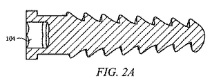
図1は、ある種の実施形態に従った、固定部材Aを示している。固定部材Aは、一般的に、海綿状のねじの特徴を有し、例えば、ツーポジション軸部であって、任意的要素である粗いセルフタッピングねじ103を備え、軟質の延髄の又は海綿状の骨に固定するように設計され、頂部は、滑らかなねじ無し部分101であってラグねじとして働くことが許容される。ねじの無い上部部分101は、斜めの開口部102を呈し、固定部材の軸部の軸線平面に対して角度(例えば、約25゜)を有している。固定部材Aの近位端は、近位端ソケット104を有し、ソケットには、キー、ねじ回し、又はレンチなどの取付具と係合する(図2B参照)。特定の実施形態においては、固定部材Aの近位端はヘックス(六角形)タイプの近位端ソケット104を有し、ソケットには、キー又はレンチ(図2b参照)に似た取付具の六角形先端部が係合する。
FIG. 1 shows a fixation member A according to certain embodiments. The fixation member A generally has the characteristics of a spongy screw, for example, a two-position shank, with an optional element, a rough self-tapping
本願において用語“取付具”とは、ツールを参照し、例えば、レンチ、キー、又はねじ回しであって、固定具の頭部を介して、対応する固定具を骨の中に挿入するのに採用され、及び/又は、係止部材の頭部のソケット104を介して、対応する係止部材を固定具に挿入するために採用される。
As used herein, the term “fixture” refers to a tool, for example, a wrench, key, or screwdriver, for inserting a corresponding fixture into the bone through the head of the fixture. Employed and / or employed to insert the corresponding locking member into the fixture via the
固定具又は係止部材の頭部のソケット104は任意の形状で良いけれども、ここでの実施形態において、両方の頭部が六角形であることは単なる例示である。すなわち、固定具又は係止部材にそれぞれの取付具を挿入するためのソケット104の形状は、任意の形状であり、それらには、六角形、五角形、正方形、三角形、十字形状、プラス(+)の記号の形状、直線状、星形形状などが例えば含まれる。特定の実施形態においては、係止部材の頭部は、固定具の頭部に比べて小さくなっているけれども、他の実施形態においては、係止部材の頭部は、固定具の頭部と同じサイズでも良い。他の特定の実施形態においては、固定具の近位端のソケット104、及び係止部材の近位端のソケット104は、形状及び/又はサイズが同一であり、一方、他の特定の実施形態においては、固定具の近位端のソケット104、及び係止部材の近位端のソケット104は、形状及び/又はサイズが同一ではない。
Although the fastener or locking
図2は、固定部材の横断面図(図2A)及び固定部材の近位端の上部平面図(図2B)を示している。固定具又は係止部材において、それぞれの取付具を挿入するためのソケット104の形状は任意の形状であって、それらには、六角形、五角形、正方形、三角形、十字形、プラス(+)記号の形状、直線状、星形形状など、例えば(下記参照)、それらは、スロット状、フィリップス、ポジドライブ、トルクス、六角形キー、ロバートソン、トリウイング、トルクセット、又は例えばスパナなどが含まれる。
FIG. 2 shows a cross-sectional view of the securing member (FIG. 2A) and a top plan view of the proximal end of the securing member (FIG. 2B). In the fixing device or the locking member, the shape of the

しかしながら、例示的な六角形(ヘックス)のソケットを固定部材の頭部(104)に設けることは以下の利点を有する。すなわち、ボール端六角形キー(又はレンチ)を使用した斜めのねじ締め及び挿入が可能になり、ねじの接触面が外部の損傷から保護され、ツールは無頭部ねじと共に使用でき、ねじとドライバーとの間には6つの接触面が存在し、ソケットの深さはくずれる傾向が低く、及び、例えば、この部分はカニュレーションに使用できる。 However, providing an exemplary hexagonal (hex) socket on the head (104) of the fixation member has the following advantages. In other words, diagonal screw tightening and insertion using a ball end hex key (or wrench) is possible, the screw contact surface is protected from external damage, the tool can be used with headless screws, screw and screwdriver There are six contact surfaces between the two and the socket depth is less prone to breakage and, for example, this part can be used for cannulation.
図3は、固定システム100を示し、固定部材Aと、係止部材Lとを備えている。2つの部材の間の角度αは、固定され、ある種の実施形態においては、25゜セットアップしている。この角度によれば、標準的な六角形の第2の取付具F2を使用することが許容され、(F1取付具は、固定具のための取付具を参照し、F2取付具は、係止部材のための取付具を参照する。)、これは、30゜までの斜めの状態において使用できるように、端部ボール六角形を具備している。他の実施形態においては、角度は1〜90゜の間の他の値に設定できる。特定の実施形態においては、角度は、15〜25゜である。30゜の角度を越えると、他の実施形態による第2の取付具F2であって、傾斜可能な六角形先端部を備えたものが使用される(差動内側機構)。
FIG. 3 shows a
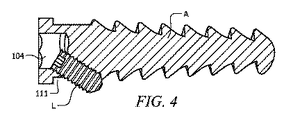
図4は、固定システムを模式的に示した横断面の平面図である。この図において、無頭部の係止部材Lは、固定部材Aの頭部の例示的な六角形形状のソケット(104)の内部において、斜めの開口部(111)に係合する。開口部の内壁面は、ねじ付き、滑らか、又は粗面になっている。開口部の片端は、固定具の近位側頭部にあり、反対側の端部は、固定具の他の側部にある。 FIG. 4 is a cross-sectional plan view schematically showing the fixing system. In this figure, a headless locking member L engages with an oblique opening (111) inside an exemplary hexagonal socket (104) on the head of the fixing member A. The inner wall surface of the opening is threaded, smooth, or rough. One end of the opening is on the proximal head of the fixture and the opposite end is on the other side of the fixture.
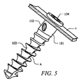
図5は、例示的な目的物(プレート)Pを保持した固定部材を示した斜視図である。 FIG. 5 is a perspective view showing a fixing member holding an exemplary object (plate) P. FIG.
図6は、第1の取付具F1であって、六角形タイプの先端部(112)を備えたものを示している。この代表例においては、取付具は、頭部又は先端部を備え、固定具のソケットに係合し、先端部の回転によってトルクを適用し、例えば、限定はしないが、ねじ回し、キー、又はレンチを用いる。先端部は、六角形のタイプに限定されない。ある種の観点における第2の取付具F2は、ボール端六角形タイプの端部を備え、係止部材のねじ止めを許容する。第2の取付具F2は、特定の実施形態において使用する場合、例えば、2つの部材の間の角度αが25゜であるか、最大でも30゜以下である場合、そのようなボール端六角形先端部の作業角度(25〜30゜)に従って、第1の取付具F1と同一の特徴を有する。この場合、サイズだけが第1の取付具F1と異なり、第2の取付具F2は、第1の取付具F1に比べて細く、特定の実施形態において、第1の取付具F1の内側ソケット104の内部に滑り込むことができる。
FIG. 6 shows a first fixture F1 with a hexagonal tip (112). In this representative example, the fixture comprises a head or tip, engages the socket of the fixture, and applies torque by rotation of the tip, such as, but not limited to, a screwdriver, key, or Use a wrench. The tip is not limited to a hexagonal type. The second fixture F2 in a certain aspect includes a ball end hexagonal type end and allows the locking member to be screwed. The second fixture F2 is used in certain embodiments, such as when the angle α between the two members is 25 ° or at most 30 ° or less, such a ball end hexagon. According to the working angle (25-30 °) of the tip, it has the same characteristics as the first fixture F1. In this case, only the size is different from the first fixture F1, and the second fixture F2 is narrower than the first fixture F1, and in a specific embodiment, the
他の実施形態においては、角度αに比べて大きな角度β、例えば2つの部材A及びLの間が30゜以上の場合に、採用される。この実施形態においては、第2の取付具F2は、傾斜可能な先端部を呈し、角度βと合致でき、内側機構を備え、取付具のハンドルに加えられる回転運動の斜めの伝達に従って、トルクを適用する。そのような機構は、限定はしないが、差動式、ねじ歯車、又は歯車のセットである。図7は、そのような機構の原理を図示し、差動歯車の模式的な原理図を示している。そのような取付具は、手によって、又は電気若しくはその他のモータによって回転させる。 In another embodiment, the angle β is larger than the angle α, for example, when the distance between the two members A and L is 30 ° or more. In this embodiment, the second fixture F2 presents a tiltable tip, can match the angle β, has an inner mechanism, and provides torque according to the oblique transmission of rotational motion applied to the handle of the fixture. Apply. Such a mechanism is, but is not limited to, a differential, a screw gear, or a set of gears. FIG. 7 illustrates the principle of such a mechanism and shows a schematic principle diagram of the differential gear. Such a fixture is rotated by hand or by an electric or other motor.
どのような機構であれ、それは、ある種の実施形態においては、斜めのねじ回しを許容することを意図し、同時に、取付具のハンドルはまっすぐ前方に維持される。そのような特徴は、局所的解剖学構造がツールの傾斜を禁止する場合に有用である。例えば、小さい切開を通した最小限の侵襲性のアプローチを使用した外科手術が実行されるとき、器具は、かかる小さな皮膚の開口部を通さなければならず、従って、軟質組織の損傷を回避するために、斜めにできない。 Whatever mechanism is intended, in certain embodiments, is intended to allow for an angled screwdriver, while at the same time the handle of the fixture is kept straight forward. Such a feature is useful when the local anatomy prohibits tool tilting. For example, when surgery is performed using a minimally invasive approach through a small incision, the instrument must pass through such a small skin opening, thus avoiding soft tissue damage Therefore, it can not be diagonal.
図8Aは、取付具における遠位端(ボール端六角形ツール)を示した拡大斜視図である。ボール端をねじの頭部に滑り入れる概念は、漏斗の挿入として知られている。基本的に、それは、ボール端の側部は、所定位置に導く(漏斗)ことを意味する。これによれば、迅速な漏斗進入を許容し、たとえ見えない用途であっても、無駄時間を解消し、完全な深さの係合は“くずれる”問題点を緩和する。 FIG. 8A is an enlarged perspective view showing a distal end (ball end hexagonal tool) in the fixture. The concept of sliding the ball end into the screw head is known as funnel insertion. Basically, it means that the side of the ball end is brought into place (funnel). This allows for rapid funnel entry, eliminates dead time, even in invisible applications, and alleviates the problem of full-depth engagement being “broken”.
図8Bは、遠位端(ボール端六角形ツール)であって、25〜30゜の角度で六角形に進入する様子を示した拡大側面図である。最大許容角度が増加すると、首部のサイズは減少し、強度もまた減少する。対照的に、ボール端ツールの強度を増加させるには、対応する首部サイズの増加と、最大許容角度の減少とを必要とする。完璧なボール端ツールを設計することは、強度と許容角度との間の理想的なバランスを選択することを意味する。図8Cは、斜めの挿入の例である。図8Dは、六角形ねじの内部に係合している第1の取付具F1を示した側面図である。 FIG. 8B is an enlarged side view showing the distal end (ball end hexagonal tool) entering the hexagon at an angle of 25-30 °. As the maximum allowable angle increases, the neck size decreases and the strength also decreases. In contrast, increasing the strength of the ball end tool requires a corresponding increase in neck size and a decrease in the maximum allowable angle. Designing a perfect ball end tool means choosing an ideal balance between strength and tolerance angle. FIG. 8C is an example of oblique insertion. FIG. 8D is a side view showing the first fixture F1 engaged inside the hexagonal screw.
図9は、係止部材Lについて、3つの可能な設計を示している。ある種の実施形態においては、係止部材Lは、固定部材Aに比べて細身であり、斜めの開口部を通って摺動し、固定部材の六角形ソケットの空間の内部に配置される。その長さは、固定部材に比べて、小さいか、等しいか、大きいかのいずれかである。その近位端は、頭部(105)を備えるか、固定部材の頭部の内部に閉塞されるような広口(106)であるか、又は無頭部(107)であるかである。どのようなタイプの係止部材Lであれ(頭部付き105、広口106、又は無頭部107)、ある種の実施形態においては、ソケットは六角形タイプの形状である。係止部材は、皮質性タイプのねじ(図9A)であって、微細なねじ(108)をその軸部全体に沿って備え、従って、固定部材の頭部の内部にある斜めのねじ付き管の中に螺入されるものか、又は海綿質タイプのねじ(図9B)であって、粗いねじ(109)を備え、骨と、滑らかなねじ無し部分(110)とを固定するように設計され、固定部材の頭部の内部の斜めのねじ無し管の中へ滑り入れるように設計されたものか、のいずれかである。そのタイプに応じて、係止部材Lは、皮質性タイプの設計においては、抗回転装置としてだけ作用し、固定部材Aのねじ緩みを防止し、又は海綿状タイプの設計においては、上述した閉塞システム及び追加的固定装置の両方であって、髄骨の内部での把持を強化し固定することを意図する。さらに、その発散性の配置に起因して、引き抜き力に逆らうV字形の設計に構築されている。どのような海綿状又は皮質性のタイプの設計が使用されるにせよ、第2の発散性部材(係止部材L)の付加は、把持及び骨内におけるパーチェスの両方を有利に増加させ、特に、海綿状及び/又は骨粗しょう症の骨において、及び、従って、骨に任意の目的物の固定の引き抜き及び固定に対抗する。
FIG. 9 shows three possible designs for the locking member L. FIG. In certain embodiments, the locking member L is slender compared to the fixing member A, slides through an oblique opening, and is disposed within the hexagon socket space of the fixing member. The length is either smaller, equal or larger than the fixed member. Its proximal end has a head (105), is a wide mouth (106) that is occluded inside the head of the fixation member, or is headless (107). Whatever type of locking member L (headed 105,
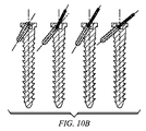
図10は、インターロック固定具及び係止部材の様々な角度パターンを示している。固定部材の内部における係止部材のある種の角度について、従って、対応する取付具を係止部材にねじ止めするのに必要とされるある種の角度と、固定部材の近位端は、そのソケットにキャビティを必要として、取付具が係止部材にアクセスするのを許容する。 FIG. 10 shows various angular patterns of interlock fixtures and locking members. For a certain angle of the locking member inside the fixing member, the certain angle required to screw the corresponding fitting to the locking member and the proximal end of the fixing member The socket requires a cavity and allows the fixture to access the locking member.
図11は、1つの実施形態による固定部材の内部にある係止部材を示しており、加えて、固定部材の内部における係止部材の角度に対応する角度を有するそれぞれの取付具を示している。この特定の実施形態においては、固定部材における近位端は、キャビティを有し、それにより、係止部材のための取付具の挿入を許容している。 FIG. 11 shows the locking member inside the fixing member according to one embodiment, and in addition, shows each fixture having an angle corresponding to the angle of the locking member inside the fixing member. . In this particular embodiment, the proximal end of the securing member has a cavity, thereby allowing the insertion of a fixture for the locking member.
図12は、例示的な実施形態による取付具と、それに対応する、固定部材の内部にある係止部材とを示している。固定部材の近位端は、キャビティを備え、これにより係止部材のための取付具の挿入を許容している。 FIG. 12 shows a fixture according to an exemplary embodiment and a corresponding locking member inside the securing member. The proximal end of the fixation member is provided with a cavity, thereby allowing the insertion of a fixture for the locking member.
ある種の実施形態においては、固定具と係止部材とは、抗生物質又はその他の医薬であって、骨の上に及び/又は中にインプラントを移植するに際して有効なものによってコーティングされる。他の実施形態においては、固定具及び/又は係止部材の表面は、粗面であり、骨の内部でより良く把持されるようになっている。 In certain embodiments, the fasteners and locking members are coated with an antibiotic or other medication that is effective in implanting the implant on and / or in the bone. In other embodiments, the surface of the fixture and / or locking member is rough so that it is better gripped within the bone.
本願に開示された任意の構成要素は、キットを構成することができる。キット中に1以上の構成要素がある場合には、キットはまた、第2の、第3の、又はその他の追加的な容器を備え、その中に、追加的な構成要素が別々に配置される。本発明によるキットは、発明の要素を収容するための手段を具備し、商業的安全のために塞いで閉じ込める。そのような容器は、射出成形又は吹き込み成形されたプラスチック容器を具備し、その中に、例えば、構成要素が保持される。 Any component disclosed in the present application can constitute a kit. If there is more than one component in the kit, the kit also includes a second, third, or other additional container in which the additional components are separately disposed. The The kit according to the invention comprises means for containing the elements of the invention and is closed and enclosed for commercial safety. Such containers comprise an injection molded or blow molded plastic container in which, for example, components are held.
キットは、固定具、係止部材、及び/又は、取付具から構成される。いくつかの事例においては、すべての構成要素は別々に販売され、一方、他の事例においては、すべての構成要素又はその部分集合が一緒に販売される。容器の数及び/又はタイプにかかわらず、本発明によるキットはまた、本発明の取付具以外の器具を備え及び/又は同封され、固定具/係止部材を動物の体内に配置するのを助ける。 The kit includes a fixture, a locking member, and / or a fixture. In some cases, all components are sold separately, while in other cases, all components or subsets thereof are sold together. Regardless of the number and / or type of containers, the kit according to the present invention may also be provided with and / or enclosed with an instrument other than the fixture of the present invention to help place the fixture / locking member in the animal's body. .
本発明の特定の実施形態においては、様々な固定具、係止部材、及び/又は、取付具が1つのキットとして提供される。例えば、様々な長さ、直径、ソケット形状、及び/又は、対応する固定具、係止部材、及び/又は、取付具の角度のものがキット内に提供される。 In certain embodiments of the present invention, various fasteners, locking members, and / or fixtures are provided as a kit. For example, various lengths, diameters, socket shapes, and / or corresponding fasteners, locking members, and / or fixture angles are provided in the kit.
上述の開示及びある種の実施形態の詳細な説明から、本発明の真の範囲及び精神から逸脱せずに、様々な変形例、追加例、及び他の代替的な実施形態が可能なことは明らかである。上述した実施形態は、本発明の原理を最良に例証するために選択及び説明され、その実際的な用途は、それにより、当業者が、想定される特定の使用に適する、様々な実施形態及び様々な変形例において、発明を使用することを可能にする。すべてのそのような変形例及び応用例は、特許請求の範囲を公平に、法律的に、及び均等物を含むように広く解釈したとき、それによって決定された発明の範囲内に包含される。 From the foregoing disclosure and detailed description of certain embodiments, various modifications, additions, and other alternative embodiments are possible without departing from the true scope and spirit of the invention. it is obvious. The above-described embodiments have been selected and described in order to best illustrate the principles of the invention, and its practical application may thereby vary in various embodiments and modes suitable for the particular use envisioned by those skilled in the art. In various variations, the invention can be used. All such modifications and applications are intended to be included within the scope of the invention as determined by the following claims when interpreted broadly to include the claims fairly, legally, and equivalents.
Claims (19)
骨組織内に進められるように形成された固定部材であって、固定部材は、近位端と、固定部材の中心軸線に沿って近位端から離間されている遠位端と、固定部材の中心軸線から固定部材の中心軸線と垂直である半径方向に沿って離間された固定部材の外面と、を有している固定部材を備え、固定部材の近位端は、固定部材の中心軸線と垂直である近位面を有し、
この固定部材は、固定部材の近位端に配置されたソケットであって、このソケットは固定部材を骨組織内に進ませるための取付具を受け入れるように形成され、ソケットは近位面におけるソケット開口と、ソケット開口から固定部材の中心軸線に沿って遠位端に向かって延びるソケット内壁と、を形成している、ソケットと、
ソケット内壁から固定部材の外面まで固定部材の中心軸線に関して斜めである中心開口軸線に沿って延びる斜めの開口部であって、中心開口軸線は近位のソケット開口を通って延びている、斜めの開口部とを有している、上記固定部材と、
近位端とこの近位端と反対の遠位端とを有する係止部材であって、係止部材は、係止部材の近位端が斜めの開口部内に位置され且つ係止部材の遠位端が外面に対して外側に延びて骨組織と係合するまで、ソケット開口を通って中心開口軸線に沿って斜めの開口部内に挿入できるように形成されサイズ合わせされている、係止部材と、を備えていることを特徴とするシステム。 A system configured to attach at least one object to bone tissue, the system comprising:
A fixation member configured to be advanced into bone tissue, wherein the fixation member includes a proximal end, a distal end spaced from the proximal end along a central axis of the fixation member, and a fixation member with the outer surface of the fixing member that is spaced along the radial direction from the center axis is perpendicular to the central axis of the fixing member, a fixing member having a proximal end of the fixing member includes a center axis of the fixing member Having a proximal surface that is vertical;
The fixation member is a socket disposed at the proximal end of the fixation member, the socket being configured to receive a fixture for advancing the fixation member into bone tissue, the socket being a socket on the proximal surface A socket forming an opening and a socket inner wall extending from the socket opening along the central axis of the securing member toward the distal end;
An oblique opening extending along a central opening axis that is oblique with respect to a central axis of the fixing member from an inner wall of the socket to an outer surface of the fixing member, the central opening axis extending through the proximal socket opening; The fixing member having an opening;
A locking member having a proximal end and a distal end opposite the proximal end , wherein the locking member is positioned at a proximal end of the locking member within the oblique opening and is remote from the locking member. to the nearest end to engage the bone tissue extends outwardly against the outer surface, is formed so as to be inserted obliquely in the opening along the central opening axis through the socket openings are aligned size, the locking member And a system characterized by comprising:
複数の固定部材であって、各固定部材が、ソケットと、ソケット内壁から外面に延びる斜めの開口部とを有している上記複数の固定部材と、
複数の係止部材であって、各々の斜めの開口部に、複数の係止部材の少なくとも1つが、ソケットを通って中心開口軸線に沿って斜めの開口部内に挿入され骨組織と係合できるように、上記係止部材の少なくとも1つが挿入されるようになっている、上記複数の係止部材と、を備えていることを特徴とするキット。 A kit comprising the system of claim 1, wherein the kit comprises:
A plurality of fixing members, each fixing member having a socket and an oblique opening extending from the socket inner wall to the outer surface;
A plurality of locking members, wherein at least one of the plurality of locking members can be inserted into the oblique opening through the socket along the central opening axis and engaged with the bone tissue in each oblique opening. Thus, a kit comprising the plurality of locking members into which at least one of the locking members is inserted.
Applications Claiming Priority (3)
| Application Number | Priority Date | Filing Date | Title |
|---|---|---|---|
| US3946408P | 2008-03-26 | 2008-03-26 | |
| US61/039,464 | 2008-03-26 | ||
| PCT/US2009/038376 WO2009120852A2 (en) | 2008-03-26 | 2009-03-26 | Universal anchor for attaching objects to bone tissue |
Related Child Applications (1)
| Application Number | Title | Priority Date | Filing Date |
|---|---|---|---|
| JP2015150310A Division JP6258269B2 (en) | 2008-03-26 | 2015-07-30 | Universal fixing device for attaching objects to bone tissue |
Publications (3)
| Publication Number | Publication Date |
|---|---|
| JP2011517591A JP2011517591A (en) | 2011-06-16 |
| JP2011517591A5 JP2011517591A5 (en) | 2012-05-17 |
| JP5788787B2 true JP5788787B2 (en) | 2015-10-07 |
Family
ID=41114711
Family Applications (2)
| Application Number | Title | Priority Date | Filing Date |
|---|---|---|---|
| JP2011502049A Active JP5788787B2 (en) | 2008-03-26 | 2009-03-26 | Universal fixing device for attaching objects to bone tissue |
| JP2015150310A Expired - Fee Related JP6258269B2 (en) | 2008-03-26 | 2015-07-30 | Universal fixing device for attaching objects to bone tissue |
Family Applications After (1)
| Application Number | Title | Priority Date | Filing Date |
|---|---|---|---|
| JP2015150310A Expired - Fee Related JP6258269B2 (en) | 2008-03-26 | 2015-07-30 | Universal fixing device for attaching objects to bone tissue |
Country Status (9)
| Country | Link |
|---|---|
| US (2) | US9084646B2 (en) |
| EP (2) | EP2285299B1 (en) |
| JP (2) | JP5788787B2 (en) |
| KR (1) | KR101602153B1 (en) |
| CN (2) | CN102046105B (en) |
| BR (1) | BRPI0911290B8 (en) |
| CA (1) | CA2719699C (en) |
| CO (1) | CO6331410A2 (en) |
| WO (1) | WO2009120852A2 (en) |
Families Citing this family (38)
| Publication number | Priority date | Publication date | Assignee | Title |
|---|---|---|---|---|
| US9084646B2 (en) | 2008-03-26 | 2015-07-21 | DePuy Synthes Products, Inc. | Universal anchor for attaching objects to bone tissue |
| BRPI0911869A2 (en) | 2008-06-05 | 2019-09-24 | Synthes Gmbh | joint disc implant |
| US8882838B2 (en) | 2008-06-05 | 2014-11-11 | DePuy Synthes Products, LLC | Articulating disc implant |
| US8328806B2 (en) * | 2008-06-24 | 2012-12-11 | Extremity Medical, Llc | Fixation system, an intramedullary fixation assembly and method of use |
| US20110230884A1 (en) * | 2008-06-24 | 2011-09-22 | Adam Mantzaris | Hybrid intramedullary fixation assembly and method of use |
| US8343199B2 (en) * | 2008-06-24 | 2013-01-01 | Extremity Medical, Llc | Intramedullary fixation screw, a fixation system, and method of fixation of the subtalar joint |
| US8303589B2 (en) | 2008-06-24 | 2012-11-06 | Extremity Medical Llc | Fixation system, an intramedullary fixation assembly and method of use |
| US8313487B2 (en) | 2008-06-24 | 2012-11-20 | Extremity Medical Llc | Fixation system, an intramedullary fixation assembly and method of use |
| US9289220B2 (en) * | 2008-06-24 | 2016-03-22 | Extremity Medical Llc | Intramedullary fixation assembly and method of use |
| US9017329B2 (en) * | 2008-06-24 | 2015-04-28 | Extremity Medical, Llc | Intramedullary fixation assembly and method of use |
| US9044282B2 (en) | 2008-06-24 | 2015-06-02 | Extremity Medical Llc | Intraosseous intramedullary fixation assembly and method of use |
| US9060808B2 (en) | 2008-12-05 | 2015-06-23 | DePuy Synthes Products, Inc. | Anchor-in-anchor system for use in bone fixation |
| BRPI0922786A2 (en) | 2008-12-05 | 2019-09-24 | Synthes Gmbh | anchor-in-anchor systems for use in bone fixation |
| WO2011116374A2 (en) * | 2010-03-19 | 2011-09-22 | K2M, Inc. | Spinal fixation apparatus and methods |
| KR101885506B1 (en) * | 2010-05-13 | 2018-08-07 | 신세스 게엠바하 | Bone screw assembly and instruments for implantation of the same |
| CN103002822B (en) * | 2010-06-09 | 2016-03-30 | 斯恩蒂斯有限公司 | For anchor system in the anchor that uses in fixing at bone |
| EP2455014B1 (en) * | 2010-11-17 | 2015-08-12 | Hyprevention | Implantable device for preventive or interventive treatment of femur fractures, associated ancillary device |
| CH705356A2 (en) * | 2011-08-11 | 2013-02-15 | Regenhu Ag | Body with a basic structure made from bone substitute material and methods of making. |
| CN102835998A (en) * | 2012-08-17 | 2012-12-26 | 苏州瑞华医院有限公司 | Novel internally fixing and locking bone fracture plate for curing of humerus collum chirurgicum fractures |
| CA2882601C (en) | 2012-08-22 | 2020-10-27 | Andreas Appenzeller | Anchor-in-anchor system |
| US20150005856A1 (en) * | 2013-06-27 | 2015-01-01 | Boston Scientific Neuromodulation Corporation | Lead anchors and systems and methods using the lead anchors |
| AU2014393634B2 (en) * | 2014-05-09 | 2019-11-21 | Abanza Tecnomed, S.L. | Device for trapping the end of at least one fascicle of soft material in a bone tunnel |
| CN107427361B (en) * | 2014-08-28 | 2021-05-07 | 科利耳有限公司 | Bone fixation device for a medical prosthesis |
| US9649133B2 (en) * | 2014-11-11 | 2017-05-16 | Intrepid Orthopedics | Supplemental fixation screw |
| CN104688285B (en) * | 2015-03-27 | 2017-09-29 | 王谦 | Shoulder joint sutures self-locking structure |
| GR20150100144A (en) * | 2015-03-30 | 2016-10-20 | Γεωργιος Κωνσταντινου Κωστακης | Dental implant with improved stability and osseointegration features |
| US9636498B2 (en) | 2015-08-03 | 2017-05-02 | Boston Scientific Neuromodulation Corporation | Lead anchor with a wedge and systems using the lead anchor |
| WO2017070335A1 (en) * | 2015-10-20 | 2017-04-27 | Implant Direct Sybron International Llc | Screw and driver tool for dental procedures |
| WO2017151438A1 (en) | 2016-02-29 | 2017-09-08 | Boston Scientific Neuromodulation Corporation | Lead anchor for an electrical stimulation system |
| WO2017201058A1 (en) | 2016-05-17 | 2017-11-23 | Boston Scientific Neuromodulation Corporation | Systems and methods for anchoring a lead for neurostimulation of a target anatomy |
| CN105997218A (en) * | 2016-06-29 | 2016-10-12 | 江苏艾迪尔医疗科技股份有限公司 | Humeral inverted intramedullary nail |
| ES2676437B1 (en) | 2017-01-19 | 2019-04-29 | Delgado Oscar Ruesga | Two-phase precision guide and its method for fixing a tripod with a short dental implant function in a low-lying maxillary bone. |
| US10709886B2 (en) | 2017-02-28 | 2020-07-14 | Boston Scientific Neuromodulation Corporation | Electrical stimulation leads and systems with elongate anchoring elements and methods of making and using |
| US10835739B2 (en) | 2017-03-24 | 2020-11-17 | Boston Scientific Neuromodulation Corporation | Electrical stimulation leads and systems with elongate anchoring elements and methods of making and using |
| US10857351B2 (en) | 2017-04-28 | 2020-12-08 | Boston Scientific Neuromodulation Corporation | Lead anchors for electrical stimulation leads and systems and methods of making and using |
| WO2020142213A1 (en) * | 2019-01-02 | 2020-07-09 | In Queue Innovations, Llc | Bone fixation system and methods of use |
| CN113662647A (en) * | 2020-05-15 | 2021-11-19 | 北京中安泰华科技有限公司 | Clavicle automatic pressurizing intramedullary nail with lock |
| US20220192720A1 (en) * | 2020-12-18 | 2022-06-23 | DePuy Synthes Products, Inc. | Screw-in-screw bone fixation system |
Family Cites Families (126)
| Publication number | Priority date | Publication date | Assignee | Title |
|---|---|---|---|---|
| US928997A (en) * | 1908-07-07 | 1909-07-27 | Emanuel Mueller | Lock-screw. |
| US1518119A (en) * | 1922-08-05 | 1924-12-02 | Aseptic Service Company | Locked fastening |
| GB303708A (en) * | 1928-04-27 | 1929-01-10 | Frank Harold Clause | Improvements in or relating to means for securing in position screws, nails or the like |
| US3295579A (en) * | 1965-03-08 | 1967-01-03 | Allis Chalmers Mfg Co | Lock bolt |
| US3474537A (en) * | 1965-10-19 | 1969-10-28 | Robert W Christensen | Dental prosthetic appliance |
| US3579831A (en) * | 1969-03-05 | 1971-05-25 | Irving J Stevens | Bone implant |
| JPS54118566U (en) * | 1978-02-07 | 1979-08-20 | ||
| JPS54118566A (en) | 1978-03-06 | 1979-09-14 | Nippon Electric Co | Method of producing laminated ceramic capacitor |
| US4338835A (en) * | 1980-01-24 | 1982-07-13 | Leon Simons | Recessed head fastener and driver therefor |
| JPS6114484Y2 (en) * | 1981-02-12 | 1986-05-07 | ||
| DE3124059A1 (en) | 1981-06-18 | 1983-01-05 | Mecron Medizinische Produkte Gmbh, 1000 Berlin | Nail for fixing fractures of the femur |
| DE3312959A1 (en) * | 1983-04-11 | 1984-10-11 | Erich 8217 Grassau Stabenau | Securing device for a wood screw |
| ATE44871T1 (en) * | 1984-09-04 | 1989-08-15 | Univ Berlin Humboldt | DISC PROSTHESIS. |
| US4754749A (en) * | 1986-04-29 | 1988-07-05 | Tsou Paul M | Surgical screw with counter-rotation prevention means |
| US4828562A (en) * | 1988-02-04 | 1989-05-09 | Pfizer Hospital Products Group, Inc. | Anterior cruciate ligament prosthesis |
| US5038978A (en) * | 1989-11-13 | 1991-08-13 | B&G Plastics, Inc. | Hanger and display support combined therewith |
| US5140877A (en) * | 1990-12-14 | 1992-08-25 | John Sloan | Hexagonal wrench |
| US5797918A (en) * | 1991-12-13 | 1998-08-25 | David A. McGuire | Flexible surgical screwdriver and methods of arthroscopic ligament reconstruction |
| US5251521A (en) | 1992-01-31 | 1993-10-12 | Bondhus Corporation | TORX-compatible elliptical driver |
| US5207529A (en) * | 1992-06-29 | 1993-05-04 | General Motors Corporation | Fastening device |
| ATE197665T1 (en) * | 1992-11-02 | 2000-12-15 | Sulzer Orthopaedie Ag | ANCHORING FOR AN ARTIFICIAL BAND |
| US5370662A (en) | 1993-06-23 | 1994-12-06 | Kevin R. Stone | Suture anchor assembly |
| FR2709412B1 (en) * | 1993-09-01 | 1995-11-24 | Tornier Sa | Screw for lumbo-sacral fixator. |
| FR2718014A1 (en) | 1994-04-05 | 1995-10-06 | Chagneau Francis | Anchor screw assembly for joint prosthesis cup implant |
| US5443469A (en) * | 1994-05-02 | 1995-08-22 | Smith; Aubrey L. | Intramedullary reaming tissue protection guard |
| GB9411693D0 (en) | 1994-06-10 | 1994-08-03 | Matthews Michael G | Surgical intramedullary nail for stabilisation of condylar and supracondylar fractures |
| US5976139A (en) | 1996-07-17 | 1999-11-02 | Bramlet; Dale G. | Surgical fastener assembly |
| AU1997797A (en) | 1996-05-31 | 1997-12-04 | Acromed Corporation | An apparatus comprising a plate and a fastener for connecting the plate to a bone portion |
| US5993463A (en) * | 1997-05-15 | 1999-11-30 | Regents Of The University Of Minnesota | Remote actuation of trajectory guide |
| WO1998053746A1 (en) * | 1997-06-02 | 1998-12-03 | Martello Jeannette M D | Soft tissue securing anchor |
| US5984681A (en) * | 1997-09-02 | 1999-11-16 | Huang; Barney K. | Dental implant and method of implanting |
| JP4126091B2 (en) | 1997-10-20 | 2008-07-30 | ジンテーズ ゲゼルシャフト ミト ベシュレンクテル ハフツング | Bone fixation device |
| US5899941A (en) * | 1997-12-09 | 1999-05-04 | Chubu Bearing Kabushiki Kaisha | Artificial intervertebral disk |
| SE9800844L (en) | 1998-03-16 | 1999-07-19 | Scandimed International Ab | Instruments for repositioning and fixation of wrist fractures |
| US6013078A (en) * | 1998-08-19 | 2000-01-11 | Lin; Chin | Securing device for bone fastener |
| US6113637A (en) * | 1998-10-22 | 2000-09-05 | Sofamor Danek Holdings, Inc. | Artificial intervertebral joint permitting translational and rotational motion |
| US6517541B1 (en) | 1998-12-23 | 2003-02-11 | Nenad Sesic | Axial intramedullary screw for the osteosynthesis of long bones |
| DE19938916A1 (en) | 1999-05-18 | 2001-02-22 | Merete Man Gmbh | Fracture bone screw |
| US6221074B1 (en) | 1999-06-10 | 2001-04-24 | Orthodyne, Inc. | Femoral intramedullary rod system |
| FR2802799B1 (en) * | 1999-12-23 | 2002-08-16 | Depuy France | SHOULDER PROSTHESIS KIT |
| JP3383257B2 (en) * | 2000-03-10 | 2003-03-04 | 株式会社ロバート・リード商会 | Rod fixing device |
| US6235033B1 (en) * | 2000-04-19 | 2001-05-22 | Synthes (Usa) | Bone fixation assembly |
| DE60117377T2 (en) * | 2000-05-25 | 2006-10-12 | Orthoplex Llc, Boston | ANCHORING SYSTEM FOR FIXING OBJECTS TO BONE |
| US6409730B1 (en) | 2000-05-31 | 2002-06-25 | Synthes (Usa) | Humeral spiral blade |
| US6629998B1 (en) | 2000-08-23 | 2003-10-07 | Chih-I Lin | Intervertebral retrieval device |
| US6849093B2 (en) * | 2001-03-09 | 2005-02-01 | Gary K. Michelson | Expansion constraining member adapted for use with an expandable interbody spinal fusion implant and method for use thereof |
| US6443954B1 (en) | 2001-04-24 | 2002-09-03 | Dale G. Bramlet | Femoral nail intramedullary system |
| US6524314B1 (en) | 2001-08-24 | 2003-02-25 | John C. Dean | Interlocking intramedullary nail |
| US6835197B2 (en) | 2001-10-17 | 2004-12-28 | Christoph Andreas Roth | Bone fixation system |
| GB2381197A (en) * | 2001-10-25 | 2003-04-30 | Corin Surgical Ltd | A surgical implant |
| US7094242B2 (en) | 2001-10-31 | 2006-08-22 | K2M, Inc. | Polyaxial drill guide |
| US6467919B1 (en) * | 2001-11-02 | 2002-10-22 | Gentex Corporation | Mirror with split ball mount and hold-open device |
| US20040019353A1 (en) | 2002-02-01 | 2004-01-29 | Freid James M. | Spinal plate system for stabilizing a portion of a spine |
| AR038680A1 (en) | 2002-02-19 | 2005-01-26 | Synthes Ag | INTERVERTEBRAL IMPLANT |
| US6681662B2 (en) | 2002-03-01 | 2004-01-27 | Bondhus Corporation | Tool with fastener engaging member |
| WO2004008980A1 (en) | 2002-07-22 | 2004-01-29 | Acumed Llc | Bone fusion system |
| CA2497278C (en) * | 2002-09-02 | 2010-05-11 | Mathys Medizinaltechnik Ag | Intervertebral implant comprising a three-part articulation |
| US6974479B2 (en) * | 2002-12-10 | 2005-12-13 | Sdgi Holdings, Inc. | System and method for blocking and/or retaining a prosthetic spinal implant |
| FR2848408B1 (en) * | 2002-12-17 | 2005-08-19 | Vitatech | DEVICE WITH ANTERIOR PLATE FOR MAINTAINING THE RACHIS |
| US6908484B2 (en) * | 2003-03-06 | 2005-06-21 | Spinecore, Inc. | Cervical disc replacement |
| CN100384384C (en) * | 2003-03-07 | 2008-04-30 | 斯恩蒂斯有限公司 | Locking screw for an intramedullary nail |
| CN1822903B (en) * | 2003-05-19 | 2012-04-18 | 丰收技术股份有限公司 | Method and apparatus for separating fluid components |
| EP1627616A4 (en) * | 2003-05-27 | 2010-12-01 | Hoya Corp | Surgical instrument |
| DE20309481U1 (en) | 2003-06-20 | 2003-09-04 | Stryker Trauma Gmbh | Device for correctly inserting a guide wire for a drilling tool into a bone |
| DE10330698B4 (en) * | 2003-07-08 | 2005-05-25 | Aesculap Ag & Co. Kg | Intervertebral implant |
| US7004629B2 (en) * | 2003-07-26 | 2006-02-28 | Arthur Joseph Shrader | Method and apparatus for hanging a resealable bag |
| US20060229729A1 (en) | 2003-08-05 | 2006-10-12 | Gordon Charles R | Expandable intervertebral implant for use with instrument |
| DE20321245U1 (en) | 2003-08-26 | 2006-06-14 | Synthes Gmbh | bone plate |
| US20050055024A1 (en) | 2003-09-08 | 2005-03-10 | James Anthony H. | Orthopaedic implant and screw assembly |
| DE20314297U1 (en) * | 2003-09-12 | 2003-11-20 | Allocon Gmbh | bone screw |
| US20050107791A1 (en) * | 2003-11-14 | 2005-05-19 | Manderson Easton L. | Intramedullary locked compression screw for stabiliziation and union of complex ankle and subtalar deformities |
| US8574268B2 (en) * | 2004-01-26 | 2013-11-05 | DePuy Synthes Product, LLC | Highly-versatile variable-angle bone plate system |
| US7637928B2 (en) | 2004-01-26 | 2009-12-29 | Synthes Usa, Llc | Variable angle locked bone fixation system |
| WO2006016384A1 (en) | 2004-08-12 | 2006-02-16 | Sintea Biotech S.P.A. | Disc prosthesis |
| US8470037B2 (en) * | 2004-08-18 | 2013-06-25 | Covidien Lp | Method and apparatus for reconstructing a ligament |
| US7780731B2 (en) | 2004-11-26 | 2010-08-24 | Spine Solutions, Inc. | Intervertebral implant |
| DK1639953T3 (en) | 2004-09-27 | 2008-09-29 | Orthofix Srl | Endomedullary stitch for the treatment of proximal femur fractures |
| ITRE20040143A1 (en) | 2004-11-19 | 2005-02-19 | Gian Luca Rovesti | SURGICAL SCREW WITH PREVENTIVE LOCKING SYSTEM OF THE SPONTANEOUS LOOSE |
| EP1855620A1 (en) * | 2005-01-11 | 2007-11-21 | Barry T. Bickley | Graft anchor |
| CA2605676A1 (en) | 2005-05-02 | 2006-11-09 | Seaspine, Inc. | Motion restoring intervertebral device |
| FR2885294B1 (en) * | 2005-05-03 | 2008-04-04 | Jerome Levieux | INTERVERTEBRAL DISC PROSTHESIS |
| US20080221623A1 (en) * | 2005-10-17 | 2008-09-11 | Gooch Hubert L | Systems and Methods for the Medical Treatment of Structural Tissue |
| US20080221624A1 (en) * | 2005-10-17 | 2008-09-11 | Gooch Hubert L | Systems and Methods for the Medical Treatment of Structural Tissue |
| GB2445346B (en) | 2005-10-21 | 2011-03-09 | Acumed Llc | Orthopedic rod with locking aperture |
| US20070123874A1 (en) | 2005-10-31 | 2007-05-31 | Czartoski Timothy J | Multiple purpose nail with oblique openings |
| US20070156145A1 (en) | 2005-12-30 | 2007-07-05 | Kentomia, Llc | Therapeutic constructions, spinal plates, cervical plates, hooks and screws |
| US8252058B2 (en) * | 2006-02-16 | 2012-08-28 | Amedica Corporation | Spinal implant with elliptical articulatory interface |
| US20100305704A1 (en) | 2006-02-27 | 2010-12-02 | Synthes Gmbh | Intervertebral implant with fixation geometry |
| US7641675B2 (en) * | 2006-03-08 | 2010-01-05 | Warsaw Orthopedic, Inc. | Flexible bone plates and methods for dynamic spinal stabilization |
| US20080033438A1 (en) * | 2006-08-04 | 2008-02-07 | Roy Frizzell | Cervical Saddle Plate |
| US8303590B2 (en) | 2007-01-26 | 2012-11-06 | Ebi, Llc | Lockable intramedullary fixation device |
| CN101662997B (en) * | 2007-03-23 | 2013-03-27 | 拜尔梅恩公司 | Screwdriver and screw member adapted thereof |
| US20080249569A1 (en) | 2007-04-03 | 2008-10-09 | Warsaw Orthopedic, Inc. | Implant Face Plates |
| FR2916624B1 (en) | 2007-05-29 | 2009-08-21 | Small Bone Innovations Interna | BONE SCREW, IN PARTICULAR OSTEOSYNTHESIS |
| US20100312286A1 (en) | 2007-10-30 | 2010-12-09 | Dell Oca Alberto A Fernandez | Variable Angle Locked Bone Plate |
| FR2923157B1 (en) | 2007-11-05 | 2010-09-17 | Hpi | PROSTHESIS OF INTERVERTEBRAL DISCS |
| US9084646B2 (en) | 2008-03-26 | 2015-07-21 | DePuy Synthes Products, Inc. | Universal anchor for attaching objects to bone tissue |
| BRPI0911869A2 (en) | 2008-06-05 | 2019-09-24 | Synthes Gmbh | joint disc implant |
| US8882838B2 (en) | 2008-06-05 | 2014-11-11 | DePuy Synthes Products, LLC | Articulating disc implant |
| EP2133034B1 (en) * | 2008-06-13 | 2011-12-28 | Orthofix S.r.l. | Intramedullary nail to be inserted into a fractured long bone |
| US8343199B2 (en) * | 2008-06-24 | 2013-01-01 | Extremity Medical, Llc | Intramedullary fixation screw, a fixation system, and method of fixation of the subtalar joint |
| US9017329B2 (en) * | 2008-06-24 | 2015-04-28 | Extremity Medical, Llc | Intramedullary fixation assembly and method of use |
| US8328806B2 (en) * | 2008-06-24 | 2012-12-11 | Extremity Medical, Llc | Fixation system, an intramedullary fixation assembly and method of use |
| US9044282B2 (en) * | 2008-06-24 | 2015-06-02 | Extremity Medical Llc | Intraosseous intramedullary fixation assembly and method of use |
| US8303589B2 (en) * | 2008-06-24 | 2012-11-06 | Extremity Medical Llc | Fixation system, an intramedullary fixation assembly and method of use |
| US20100121325A1 (en) * | 2008-06-24 | 2010-05-13 | Jeff Tyber | Hybrid intramedullary fixation assembly and method of use |
| US20110230884A1 (en) | 2008-06-24 | 2011-09-22 | Adam Mantzaris | Hybrid intramedullary fixation assembly and method of use |
| US20110125153A1 (en) * | 2008-06-24 | 2011-05-26 | Jeff Tyber | Intramedullary fixation assembly and method of use |
| US8313487B2 (en) * | 2008-06-24 | 2012-11-20 | Extremity Medical Llc | Fixation system, an intramedullary fixation assembly and method of use |
| US20090326545A1 (en) * | 2008-06-26 | 2009-12-31 | Amedica Corporation | Systems and methods for inserting a bone anchor without a pilot hole |
| WO2010017357A1 (en) | 2008-08-07 | 2010-02-11 | K2M, Inc. | Bone screw assembly |
| US8328872B2 (en) | 2008-09-02 | 2012-12-11 | Globus Medical, Inc. | Intervertebral fusion implant |
| US8231625B2 (en) | 2008-09-03 | 2012-07-31 | The Cleveland Clinic Foundation | Modular bone fixation device for treatment of fractures and related methods |
| US9060808B2 (en) * | 2008-12-05 | 2015-06-23 | DePuy Synthes Products, Inc. | Anchor-in-anchor system for use in bone fixation |
| BRPI0922786A2 (en) | 2008-12-05 | 2019-09-24 | Synthes Gmbh | anchor-in-anchor systems for use in bone fixation |
| US20100160924A1 (en) * | 2008-12-23 | 2010-06-24 | Howmedica Osteonics Corp. | Drill guide with angle verification |
| CN101507652A (en) | 2009-03-20 | 2009-08-19 | 周志海 | Knee joint approach intramedullary nail |
| US10335214B2 (en) | 2009-04-24 | 2019-07-02 | DePuy Synthes Products, Inc. | Multiplexed screws |
| CN102470005B (en) * | 2009-07-01 | 2014-11-05 | 新特斯有限责任公司 | Intramedullary nail and protruding screw locking mechanism |
| BR112012005187A2 (en) | 2009-09-14 | 2017-09-12 | Synthes Gmbh | VARIABLE ANGLE COMPRESSION PLATE |
| US8486116B2 (en) | 2010-01-08 | 2013-07-16 | Biomet Manufacturing Ring Corporation | Variable angle locking screw |
| WO2011116374A2 (en) * | 2010-03-19 | 2011-09-22 | K2M, Inc. | Spinal fixation apparatus and methods |
| KR101885506B1 (en) * | 2010-05-13 | 2018-08-07 | 신세스 게엠바하 | Bone screw assembly and instruments for implantation of the same |
| CN103002822B (en) | 2010-06-09 | 2016-03-30 | 斯恩蒂斯有限公司 | For anchor system in the anchor that uses in fixing at bone |
| EP2460484A1 (en) | 2010-12-01 | 2012-06-06 | FACET-LINK Inc. | Variable angle bone screw fixation assembly |
| CA2824962C (en) | 2011-01-28 | 2018-12-11 | DePuy Synthes Products, LLC | Reamer guide systems |
-
2009
- 2009-03-26 US US12/934,196 patent/US9084646B2/en not_active Expired - Fee Related
- 2009-03-26 CN CN200980118021.0A patent/CN102046105B/en not_active Expired - Fee Related
- 2009-03-26 CA CA2719699A patent/CA2719699C/en active Active
- 2009-03-26 WO PCT/US2009/038376 patent/WO2009120852A2/en active Application Filing
- 2009-03-26 BR BRPI0911290A patent/BRPI0911290B8/en not_active IP Right Cessation
- 2009-03-26 JP JP2011502049A patent/JP5788787B2/en active Active
- 2009-03-26 KR KR1020107023629A patent/KR101602153B1/en active IP Right Grant
- 2009-03-26 EP EP09724639.1A patent/EP2285299B1/en active Active
- 2009-03-26 CN CN201410086633.9A patent/CN104068925B/en not_active Expired - Fee Related
- 2009-03-26 EP EP16001477.5A patent/EP3108834B1/en active Active
-
2010
- 2010-10-26 CO CO10132564A patent/CO6331410A2/en active IP Right Grant
-
2015
- 2015-06-16 US US14/740,904 patent/US10045804B2/en active Active
- 2015-07-30 JP JP2015150310A patent/JP6258269B2/en not_active Expired - Fee Related
Also Published As
| Publication number | Publication date |
|---|---|
| CN104068925A (en) | 2014-10-01 |
| US20110022066A1 (en) | 2011-01-27 |
| EP3108834A1 (en) | 2016-12-28 |
| CO6331410A2 (en) | 2011-10-20 |
| US9084646B2 (en) | 2015-07-21 |
| JP2011517591A (en) | 2011-06-16 |
| US20160100871A1 (en) | 2016-04-14 |
| US10045804B2 (en) | 2018-08-14 |
| EP2285299A2 (en) | 2011-02-23 |
| KR101602153B1 (en) | 2016-03-10 |
| JP6258269B2 (en) | 2018-01-10 |
| BRPI0911290B1 (en) | 2020-02-11 |
| WO2009120852A2 (en) | 2009-10-01 |
| JP2015192911A (en) | 2015-11-05 |
| EP2285299B1 (en) | 2016-07-06 |
| BRPI0911290A2 (en) | 2015-09-29 |
| KR20110000660A (en) | 2011-01-04 |
| EP2285299A4 (en) | 2014-07-30 |
| CN104068925B (en) | 2017-07-14 |
| CA2719699A1 (en) | 2009-10-01 |
| EP3108834B1 (en) | 2019-05-29 |
| CN102046105B (en) | 2014-04-09 |
| WO2009120852A3 (en) | 2009-12-23 |
| BRPI0911290B8 (en) | 2021-06-22 |
| CA2719699C (en) | 2018-05-15 |
| CN102046105A (en) | 2011-05-04 |
Similar Documents
| Publication | Publication Date | Title |
|---|---|---|
| JP6258269B2 (en) | Universal fixing device for attaching objects to bone tissue | |
| EP1398000B1 (en) | Surgical nail and screw fixation system | |
| US8287550B2 (en) | Bone screw retaining system | |
| US8277490B2 (en) | Translational manipulation polyaxial screw head | |
| JP5756118B2 (en) | Fixed support pin with variable angle | |
| EP2254493B1 (en) | Variable axis locking mechanism for use in orthopedic implants | |
| US8617225B2 (en) | Spline drive for threaded post-type bone anchors | |
| KR20090064407A (en) | Hybrid bone fixation apparatus | |
| AU2009230888A1 (en) | Tool jig for bone implant assembly | |
| US20130041412A1 (en) | Flexible pedicle screws | |
| US20150342656A1 (en) | Fracture reduction structure | |
| US10751100B2 (en) | Bone screws and surgical sets comprising bone screws |
Legal Events
| Date | Code | Title | Description |
|---|---|---|---|
| A521 | Request for written amendment filed |
Free format text: JAPANESE INTERMEDIATE CODE: A523 Effective date: 20120326 |
|
| A621 | Written request for application examination |
Free format text: JAPANESE INTERMEDIATE CODE: A621 Effective date: 20120326 |
|
| A977 | Report on retrieval |
Free format text: JAPANESE INTERMEDIATE CODE: A971007 Effective date: 20130515 |
|
| A131 | Notification of reasons for refusal |
Free format text: JAPANESE INTERMEDIATE CODE: A131 Effective date: 20130605 |
|
| A601 | Written request for extension of time |
Free format text: JAPANESE INTERMEDIATE CODE: A601 Effective date: 20130826 |
|
| A602 | Written permission of extension of time |
Free format text: JAPANESE INTERMEDIATE CODE: A602 Effective date: 20130902 |
|
| A601 | Written request for extension of time |
Free format text: JAPANESE INTERMEDIATE CODE: A601 Effective date: 20130930 |
|
| A602 | Written permission of extension of time |
Free format text: JAPANESE INTERMEDIATE CODE: A602 Effective date: 20131007 |
|
| A521 | Request for written amendment filed |
Free format text: JAPANESE INTERMEDIATE CODE: A523 Effective date: 20131205 |
|
| A131 | Notification of reasons for refusal |
Free format text: JAPANESE INTERMEDIATE CODE: A131 Effective date: 20140602 |
|
| A521 | Request for written amendment filed |
Free format text: JAPANESE INTERMEDIATE CODE: A523 Effective date: 20140819 |
|
| A131 | Notification of reasons for refusal |
Free format text: JAPANESE INTERMEDIATE CODE: A131 Effective date: 20150302 |
|
| A521 | Request for written amendment filed |
Free format text: JAPANESE INTERMEDIATE CODE: A523 Effective date: 20150528 |
|
| TRDD | Decision of grant or rejection written | ||
| A01 | Written decision to grant a patent or to grant a registration (utility model) |
Free format text: JAPANESE INTERMEDIATE CODE: A01 Effective date: 20150701 |
|
| A61 | First payment of annual fees (during grant procedure) |
Free format text: JAPANESE INTERMEDIATE CODE: A61 Effective date: 20150730 |
|
| R150 | Certificate of patent or registration of utility model |
Ref document number: 5788787 Country of ref document: JP Free format text: JAPANESE INTERMEDIATE CODE: R150 |
|
| R250 | Receipt of annual fees |
Free format text: JAPANESE INTERMEDIATE CODE: R250 |
|
| R250 | Receipt of annual fees |
Free format text: JAPANESE INTERMEDIATE CODE: R250 |
|
| R250 | Receipt of annual fees |
Free format text: JAPANESE INTERMEDIATE CODE: R250 |
|
| R250 | Receipt of annual fees |
Free format text: JAPANESE INTERMEDIATE CODE: R250 |
|
| R250 | Receipt of annual fees |
Free format text: JAPANESE INTERMEDIATE CODE: R250 |