JP5759060B2 - Power supply device and control method thereof - Google Patents
Power supply device and control method thereof Download PDFInfo
- Publication number
- JP5759060B2 JP5759060B2 JP2014500943A JP2014500943A JP5759060B2 JP 5759060 B2 JP5759060 B2 JP 5759060B2 JP 2014500943 A JP2014500943 A JP 2014500943A JP 2014500943 A JP2014500943 A JP 2014500943A JP 5759060 B2 JP5759060 B2 JP 5759060B2
- Authority
- JP
- Japan
- Prior art keywords
- power supply
- voltage
- power
- power source
- dcdc converter
- Prior art date
- Legal status (The legal status is an assumption and is not a legal conclusion. Google has not performed a legal analysis and makes no representation as to the accuracy of the status listed.)
- Active
Links
- 238000000034 method Methods 0.000 title claims description 30
- HEZMWWAKWCSUCB-PHDIDXHHSA-N (3R,4R)-3,4-dihydroxycyclohexa-1,5-diene-1-carboxylic acid Chemical compound O[C@@H]1C=CC(C(O)=O)=C[C@H]1O HEZMWWAKWCSUCB-PHDIDXHHSA-N 0.000 claims description 83
- 238000007599 discharging Methods 0.000 claims description 13
- 238000009413 insulation Methods 0.000 claims description 13
- 230000001172 regenerating effect Effects 0.000 claims description 13
- 230000009466 transformation Effects 0.000 claims description 6
- 239000003990 capacitor Substances 0.000 description 17
- 230000008569 process Effects 0.000 description 14
- 238000005259 measurement Methods 0.000 description 8
- 230000007423 decrease Effects 0.000 description 7
- 239000004065 semiconductor Substances 0.000 description 5
- 238000010586 diagram Methods 0.000 description 4
- WHXSMMKQMYFTQS-UHFFFAOYSA-N Lithium Chemical compound [Li] WHXSMMKQMYFTQS-UHFFFAOYSA-N 0.000 description 3
- 230000002457 bidirectional effect Effects 0.000 description 3
- 229910052744 lithium Inorganic materials 0.000 description 3
- 238000012545 processing Methods 0.000 description 3
- 238000013459 approach Methods 0.000 description 2
- 230000005540 biological transmission Effects 0.000 description 2
- 238000004590 computer program Methods 0.000 description 2
- 230000005669 field effect Effects 0.000 description 2
- 238000009499 grossing Methods 0.000 description 2
- 230000010365 information processing Effects 0.000 description 2
- 229910001416 lithium ion Inorganic materials 0.000 description 2
- 230000015556 catabolic process Effects 0.000 description 1
- 230000008859 change Effects 0.000 description 1
- 238000006243 chemical reaction Methods 0.000 description 1
- 238000004891 communication Methods 0.000 description 1
- 230000006378 damage Effects 0.000 description 1
- 230000000694 effects Effects 0.000 description 1
- 229910052987 metal hydride Inorganic materials 0.000 description 1
- 238000012986 modification Methods 0.000 description 1
- 230000004048 modification Effects 0.000 description 1
- 229910052759 nickel Inorganic materials 0.000 description 1
- PXHVJJICTQNCMI-UHFFFAOYSA-N nickel Substances [Ni] PXHVJJICTQNCMI-UHFFFAOYSA-N 0.000 description 1
- -1 nickel metal hydride Chemical class 0.000 description 1
- 230000008929 regeneration Effects 0.000 description 1
- 238000011069 regeneration method Methods 0.000 description 1
Images


Classifications
-
- H—ELECTRICITY
- H02—GENERATION; CONVERSION OR DISTRIBUTION OF ELECTRIC POWER
- H02P—CONTROL OR REGULATION OF ELECTRIC MOTORS, ELECTRIC GENERATORS OR DYNAMO-ELECTRIC CONVERTERS; CONTROLLING TRANSFORMERS, REACTORS OR CHOKE COILS
- H02P6/00—Arrangements for controlling synchronous motors or other dynamo-electric motors using electronic commutation dependent on the rotor position; Electronic commutators therefor
- H02P6/28—Arrangements for controlling current
-
- H—ELECTRICITY
- H02—GENERATION; CONVERSION OR DISTRIBUTION OF ELECTRIC POWER
- H02M—APPARATUS FOR CONVERSION BETWEEN AC AND AC, BETWEEN AC AND DC, OR BETWEEN DC AND DC, AND FOR USE WITH MAINS OR SIMILAR POWER SUPPLY SYSTEMS; CONVERSION OF DC OR AC INPUT POWER INTO SURGE OUTPUT POWER; CONTROL OR REGULATION THEREOF
- H02M3/00—Conversion of dc power input into dc power output
- H02M3/22—Conversion of dc power input into dc power output with intermediate conversion into ac
- H02M3/24—Conversion of dc power input into dc power output with intermediate conversion into ac by static converters
- H02M3/28—Conversion of dc power input into dc power output with intermediate conversion into ac by static converters using discharge tubes with control electrode or semiconductor devices with control electrode to produce the intermediate ac
- H02M3/325—Conversion of dc power input into dc power output with intermediate conversion into ac by static converters using discharge tubes with control electrode or semiconductor devices with control electrode to produce the intermediate ac using devices of a triode or a transistor type requiring continuous application of a control signal
- H02M3/335—Conversion of dc power input into dc power output with intermediate conversion into ac by static converters using discharge tubes with control electrode or semiconductor devices with control electrode to produce the intermediate ac using devices of a triode or a transistor type requiring continuous application of a control signal using semiconductor devices only
- H02M3/33569—Conversion of dc power input into dc power output with intermediate conversion into ac by static converters using discharge tubes with control electrode or semiconductor devices with control electrode to produce the intermediate ac using devices of a triode or a transistor type requiring continuous application of a control signal using semiconductor devices only having several active switching elements
- H02M3/33576—Conversion of dc power input into dc power output with intermediate conversion into ac by static converters using discharge tubes with control electrode or semiconductor devices with control electrode to produce the intermediate ac using devices of a triode or a transistor type requiring continuous application of a control signal using semiconductor devices only having several active switching elements having at least one active switching element at the secondary side of an isolation transformer
-
- B—PERFORMING OPERATIONS; TRANSPORTING
- B60—VEHICLES IN GENERAL
- B60L—PROPULSION OF ELECTRICALLY-PROPELLED VEHICLES; SUPPLYING ELECTRIC POWER FOR AUXILIARY EQUIPMENT OF ELECTRICALLY-PROPELLED VEHICLES; ELECTRODYNAMIC BRAKE SYSTEMS FOR VEHICLES IN GENERAL; MAGNETIC SUSPENSION OR LEVITATION FOR VEHICLES; MONITORING OPERATING VARIABLES OF ELECTRICALLY-PROPELLED VEHICLES; ELECTRIC SAFETY DEVICES FOR ELECTRICALLY-PROPELLED VEHICLES
- B60L15/00—Methods, circuits, or devices for controlling the traction-motor speed of electrically-propelled vehicles
- B60L15/007—Physical arrangements or structures of drive train converters specially adapted for the propulsion motors of electric vehicles
-
- B—PERFORMING OPERATIONS; TRANSPORTING
- B60—VEHICLES IN GENERAL
- B60L—PROPULSION OF ELECTRICALLY-PROPELLED VEHICLES; SUPPLYING ELECTRIC POWER FOR AUXILIARY EQUIPMENT OF ELECTRICALLY-PROPELLED VEHICLES; ELECTRODYNAMIC BRAKE SYSTEMS FOR VEHICLES IN GENERAL; MAGNETIC SUSPENSION OR LEVITATION FOR VEHICLES; MONITORING OPERATING VARIABLES OF ELECTRICALLY-PROPELLED VEHICLES; ELECTRIC SAFETY DEVICES FOR ELECTRICALLY-PROPELLED VEHICLES
- B60L3/00—Electric devices on electrically-propelled vehicles for safety purposes; Monitoring operating variables, e.g. speed, deceleration or energy consumption
- B60L3/0023—Detecting, eliminating, remedying or compensating for drive train abnormalities, e.g. failures within the drive train
- B60L3/0046—Detecting, eliminating, remedying or compensating for drive train abnormalities, e.g. failures within the drive train relating to electric energy storage systems, e.g. batteries or capacitors
-
- B—PERFORMING OPERATIONS; TRANSPORTING
- B60—VEHICLES IN GENERAL
- B60L—PROPULSION OF ELECTRICALLY-PROPELLED VEHICLES; SUPPLYING ELECTRIC POWER FOR AUXILIARY EQUIPMENT OF ELECTRICALLY-PROPELLED VEHICLES; ELECTRODYNAMIC BRAKE SYSTEMS FOR VEHICLES IN GENERAL; MAGNETIC SUSPENSION OR LEVITATION FOR VEHICLES; MONITORING OPERATING VARIABLES OF ELECTRICALLY-PROPELLED VEHICLES; ELECTRIC SAFETY DEVICES FOR ELECTRICALLY-PROPELLED VEHICLES
- B60L50/00—Electric propulsion with power supplied within the vehicle
- B60L50/40—Electric propulsion with power supplied within the vehicle using propulsion power supplied by capacitors
-
- B—PERFORMING OPERATIONS; TRANSPORTING
- B60—VEHICLES IN GENERAL
- B60L—PROPULSION OF ELECTRICALLY-PROPELLED VEHICLES; SUPPLYING ELECTRIC POWER FOR AUXILIARY EQUIPMENT OF ELECTRICALLY-PROPELLED VEHICLES; ELECTRODYNAMIC BRAKE SYSTEMS FOR VEHICLES IN GENERAL; MAGNETIC SUSPENSION OR LEVITATION FOR VEHICLES; MONITORING OPERATING VARIABLES OF ELECTRICALLY-PROPELLED VEHICLES; ELECTRIC SAFETY DEVICES FOR ELECTRICALLY-PROPELLED VEHICLES
- B60L50/00—Electric propulsion with power supplied within the vehicle
- B60L50/50—Electric propulsion with power supplied within the vehicle using propulsion power supplied by batteries or fuel cells
- B60L50/51—Electric propulsion with power supplied within the vehicle using propulsion power supplied by batteries or fuel cells characterised by AC-motors
-
- B—PERFORMING OPERATIONS; TRANSPORTING
- B60—VEHICLES IN GENERAL
- B60L—PROPULSION OF ELECTRICALLY-PROPELLED VEHICLES; SUPPLYING ELECTRIC POWER FOR AUXILIARY EQUIPMENT OF ELECTRICALLY-PROPELLED VEHICLES; ELECTRODYNAMIC BRAKE SYSTEMS FOR VEHICLES IN GENERAL; MAGNETIC SUSPENSION OR LEVITATION FOR VEHICLES; MONITORING OPERATING VARIABLES OF ELECTRICALLY-PROPELLED VEHICLES; ELECTRIC SAFETY DEVICES FOR ELECTRICALLY-PROPELLED VEHICLES
- B60L58/00—Methods or circuit arrangements for monitoring or controlling batteries or fuel cells, specially adapted for electric vehicles
- B60L58/10—Methods or circuit arrangements for monitoring or controlling batteries or fuel cells, specially adapted for electric vehicles for monitoring or controlling batteries
- B60L58/12—Methods or circuit arrangements for monitoring or controlling batteries or fuel cells, specially adapted for electric vehicles for monitoring or controlling batteries responding to state of charge [SoC]
- B60L58/15—Preventing overcharging
-
- B—PERFORMING OPERATIONS; TRANSPORTING
- B60—VEHICLES IN GENERAL
- B60L—PROPULSION OF ELECTRICALLY-PROPELLED VEHICLES; SUPPLYING ELECTRIC POWER FOR AUXILIARY EQUIPMENT OF ELECTRICALLY-PROPELLED VEHICLES; ELECTRODYNAMIC BRAKE SYSTEMS FOR VEHICLES IN GENERAL; MAGNETIC SUSPENSION OR LEVITATION FOR VEHICLES; MONITORING OPERATING VARIABLES OF ELECTRICALLY-PROPELLED VEHICLES; ELECTRIC SAFETY DEVICES FOR ELECTRICALLY-PROPELLED VEHICLES
- B60L7/00—Electrodynamic brake systems for vehicles in general
- B60L7/10—Dynamic electric regenerative braking
- B60L7/14—Dynamic electric regenerative braking for vehicles propelled by ac motors
-
- B—PERFORMING OPERATIONS; TRANSPORTING
- B60—VEHICLES IN GENERAL
- B60L—PROPULSION OF ELECTRICALLY-PROPELLED VEHICLES; SUPPLYING ELECTRIC POWER FOR AUXILIARY EQUIPMENT OF ELECTRICALLY-PROPELLED VEHICLES; ELECTRODYNAMIC BRAKE SYSTEMS FOR VEHICLES IN GENERAL; MAGNETIC SUSPENSION OR LEVITATION FOR VEHICLES; MONITORING OPERATING VARIABLES OF ELECTRICALLY-PROPELLED VEHICLES; ELECTRIC SAFETY DEVICES FOR ELECTRICALLY-PROPELLED VEHICLES
- B60L2210/00—Converter types
- B60L2210/10—DC to DC converters
-
- B—PERFORMING OPERATIONS; TRANSPORTING
- B60—VEHICLES IN GENERAL
- B60L—PROPULSION OF ELECTRICALLY-PROPELLED VEHICLES; SUPPLYING ELECTRIC POWER FOR AUXILIARY EQUIPMENT OF ELECTRICALLY-PROPELLED VEHICLES; ELECTRODYNAMIC BRAKE SYSTEMS FOR VEHICLES IN GENERAL; MAGNETIC SUSPENSION OR LEVITATION FOR VEHICLES; MONITORING OPERATING VARIABLES OF ELECTRICALLY-PROPELLED VEHICLES; ELECTRIC SAFETY DEVICES FOR ELECTRICALLY-PROPELLED VEHICLES
- B60L2240/00—Control parameters of input or output; Target parameters
- B60L2240/40—Drive Train control parameters
- B60L2240/54—Drive Train control parameters related to batteries
- B60L2240/547—Voltage
-
- B—PERFORMING OPERATIONS; TRANSPORTING
- B60—VEHICLES IN GENERAL
- B60L—PROPULSION OF ELECTRICALLY-PROPELLED VEHICLES; SUPPLYING ELECTRIC POWER FOR AUXILIARY EQUIPMENT OF ELECTRICALLY-PROPELLED VEHICLES; ELECTRODYNAMIC BRAKE SYSTEMS FOR VEHICLES IN GENERAL; MAGNETIC SUSPENSION OR LEVITATION FOR VEHICLES; MONITORING OPERATING VARIABLES OF ELECTRICALLY-PROPELLED VEHICLES; ELECTRIC SAFETY DEVICES FOR ELECTRICALLY-PROPELLED VEHICLES
- B60L2240/00—Control parameters of input or output; Target parameters
- B60L2240/40—Drive Train control parameters
- B60L2240/54—Drive Train control parameters related to batteries
- B60L2240/549—Current
-
- H—ELECTRICITY
- H02—GENERATION; CONVERSION OR DISTRIBUTION OF ELECTRIC POWER
- H02M—APPARATUS FOR CONVERSION BETWEEN AC AND AC, BETWEEN AC AND DC, OR BETWEEN DC AND DC, AND FOR USE WITH MAINS OR SIMILAR POWER SUPPLY SYSTEMS; CONVERSION OF DC OR AC INPUT POWER INTO SURGE OUTPUT POWER; CONTROL OR REGULATION THEREOF
- H02M1/00—Details of apparatus for conversion
- H02M1/0083—Converters characterised by their input or output configuration
- H02M1/0093—Converters characterised by their input or output configuration wherein the output is created by adding a regulated voltage to or subtracting it from an unregulated input
-
- Y—GENERAL TAGGING OF NEW TECHNOLOGICAL DEVELOPMENTS; GENERAL TAGGING OF CROSS-SECTIONAL TECHNOLOGIES SPANNING OVER SEVERAL SECTIONS OF THE IPC; TECHNICAL SUBJECTS COVERED BY FORMER USPC CROSS-REFERENCE ART COLLECTIONS [XRACs] AND DIGESTS
- Y02—TECHNOLOGIES OR APPLICATIONS FOR MITIGATION OR ADAPTATION AGAINST CLIMATE CHANGE
- Y02T—CLIMATE CHANGE MITIGATION TECHNOLOGIES RELATED TO TRANSPORTATION
- Y02T10/00—Road transport of goods or passengers
- Y02T10/60—Other road transportation technologies with climate change mitigation effect
- Y02T10/64—Electric machine technologies in electromobility
-
- Y—GENERAL TAGGING OF NEW TECHNOLOGICAL DEVELOPMENTS; GENERAL TAGGING OF CROSS-SECTIONAL TECHNOLOGIES SPANNING OVER SEVERAL SECTIONS OF THE IPC; TECHNICAL SUBJECTS COVERED BY FORMER USPC CROSS-REFERENCE ART COLLECTIONS [XRACs] AND DIGESTS
- Y02—TECHNOLOGIES OR APPLICATIONS FOR MITIGATION OR ADAPTATION AGAINST CLIMATE CHANGE
- Y02T—CLIMATE CHANGE MITIGATION TECHNOLOGIES RELATED TO TRANSPORTATION
- Y02T10/00—Road transport of goods or passengers
- Y02T10/60—Other road transportation technologies with climate change mitigation effect
- Y02T10/70—Energy storage systems for electromobility, e.g. batteries
-
- Y—GENERAL TAGGING OF NEW TECHNOLOGICAL DEVELOPMENTS; GENERAL TAGGING OF CROSS-SECTIONAL TECHNOLOGIES SPANNING OVER SEVERAL SECTIONS OF THE IPC; TECHNICAL SUBJECTS COVERED BY FORMER USPC CROSS-REFERENCE ART COLLECTIONS [XRACs] AND DIGESTS
- Y02—TECHNOLOGIES OR APPLICATIONS FOR MITIGATION OR ADAPTATION AGAINST CLIMATE CHANGE
- Y02T—CLIMATE CHANGE MITIGATION TECHNOLOGIES RELATED TO TRANSPORTATION
- Y02T10/00—Road transport of goods or passengers
- Y02T10/60—Other road transportation technologies with climate change mitigation effect
- Y02T10/72—Electric energy management in electromobility
Landscapes
- Engineering & Computer Science (AREA)
- Power Engineering (AREA)
- Transportation (AREA)
- Mechanical Engineering (AREA)
- Life Sciences & Earth Sciences (AREA)
- Sustainable Development (AREA)
- Sustainable Energy (AREA)
- Electric Propulsion And Braking For Vehicles (AREA)
- Dc-Dc Converters (AREA)
Description
本発明は、車両駆動用モータに電力を供給する電源装置及びその制御方法に関する。 The present invention relates to a power supply apparatus that supplies power to a vehicle drive motor and a control method thereof.
例えば電気自動車(EV)やハイブリッド電気自動車(HEV)等の車両に用いられる電源装置が車両駆動用モータにより回生された電力を有効に回収するための技術が従来から提案されている(例えば、特許文献1参照)。 For example, a technique for effectively recovering electric power regenerated by a vehicle driving motor by a power supply device used in a vehicle such as an electric vehicle (EV) or a hybrid electric vehicle (HEV) has been proposed (for example, a patent) Reference 1).
特許文献1の電源装置は、インバータに対して電力を充放電可能な電池とコンデンサとを直列に接続するか、或いは電池のみを接続するかを切り替えるスイッチを備える。そして、コンデンサの電圧が所定値よりも低い場合、電池とコンデンサとを直列に接続して回生電力を電池及びコンデンサの両方に供給し、コンデンサの電圧が所定値よりも高い場合、電池のみを接続して回生電力を電池のみに供給している。 The power supply apparatus of patent document 1 is provided with the switch which switches whether the battery and capacitor | condenser which can charge / discharge electric power with respect to an inverter are connected in series, or only a battery is connected. When the capacitor voltage is lower than the predetermined value, connect the battery and capacitor in series to supply regenerative power to both the battery and the capacitor. When the capacitor voltage is higher than the predetermined value, connect only the battery. The regenerative power is supplied only to the battery.
しかし、特許文献1では、車両が力行を続けた場合、コンデンサの電圧が電池よりも先に無くなり、電池の電力のみで車両駆動用モータを駆動しなければならない。したがって、電池の充電状態が低い時であっても車両駆動用モータの最大出力値を保障するために、インバータは電気容量の大きな半導体素子を使用しなければならないので、インバータが大型化するという課題があった。 However, in Patent Document 1, when the vehicle continues to power, the voltage of the capacitor disappears before the battery, and the vehicle driving motor must be driven only by the power of the battery. Therefore, in order to guarantee the maximum output value of the vehicle drive motor even when the state of charge of the battery is low, the inverter must use a semiconductor element having a large electric capacity, so that the problem of increasing the size of the inverter was there.
本発明は上記課題に鑑みて成されたものであり、その目的は、インバータに入力される直流電圧を高く維持することにより、インバータ内で使用する半導体素子の電流容量を削減してインバータを小型化することができる電源装置及びその制御方法を提供することである。 The present invention has been made in view of the above problems, and its purpose is to reduce the current capacity of the semiconductor elements used in the inverter and to reduce the size of the inverter by maintaining a high DC voltage input to the inverter. It is an object to provide a power supply apparatus and a control method thereof.
上記目的を達成するため、本発明の第1態様に係わる電源装置は、電力を充放電可能な第1電源と、第1電源に直列に接続された、電力を充放電可能な第2電源と、一次側端子に第1電源が接続され、二次側端子に第2電源が接続された絶縁型DCDCコンバータと、絶縁型DCDCコンバータを用いて第2電源の電圧を制御する電源制御部とを備える。直列に接続された第1電源及び第2電源から出力される直流電圧は、第1のインバータに入力され、第1のインバータにより交流電圧に変換されてから車両駆動用モータへ供給される。 In order to achieve the above object, a power supply apparatus according to the first aspect of the present invention includes a first power supply capable of charging and discharging power, a second power supply connected in series to the first power supply and capable of charging and discharging power. An isolated DCDC converter in which a first power supply is connected to the primary side terminal and a second power supply is connected to the secondary side terminal, and a power supply control unit that controls the voltage of the second power supply using the isolated DCDC converter. Prepare. The DC voltage output from the first power supply and the second power supply connected in series is input to the first inverter, converted into an AC voltage by the first inverter, and then supplied to the vehicle drive motor.
本発明の第2態様に係わる電源装置の制御方法は、前記第1電源と、前記第2電源と、前記絶縁型DCDCコンバータとを備え、直列に接続された第1電源及び第2電源から出力される直流電圧が、第1のインバータに入力され、第1のインバータにより交流電圧に変換されてから車両駆動用モータへ供給される電源装置の制御方法であって、絶縁型DCDCコンバータを用いて第2電源の電圧を制御する。 The control method of the power supply device according to the second aspect of the present invention includes the first power supply, the second power supply, and the isolated DCDC converter, and outputs from the first power supply and the second power supply connected in series. A control method for a power supply apparatus in which a DC voltage is input to a first inverter, converted into an AC voltage by the first inverter, and then supplied to a vehicle driving motor, using an isolated DCDC converter Control the voltage of the second power source.
以下図面を参照して、本発明の実施形態を説明する。図面の記載において同一部分には同一符号を付している。 Embodiments of the present invention will be described below with reference to the drawings. In the description of the drawings, the same parts are denoted by the same reference numerals.
(第1実施形態)
[電源装置の構成]
図1を参照して、第1実施形態に係わる電源装置の構成、及び電源装置に接続される第1のインバータ5及び車両駆動用モータ6について説明する。第1実施形態に係わる電源装置は、電力を充放電可能な第1電源1aと、第1電源1aに直列に接続された、電力を充放電可能な第2電源2と、一次側端子に第1電源1aが接続され、二次側端子に第2電源2が接続された絶縁型DCDCコンバータ3aと、絶縁型DCDCコンバータ3aを用いて第2電源2の電圧を制御する電源制御部4とを備える。なお、本明細書において「接続」とは、電気的な接続を意味し、機械的な接続を意味していない。(First embodiment)
[Configuration of power supply unit]
With reference to FIG. 1, the structure of the power supply device concerning 1st Embodiment, and the
第1電源1aの正極と第2電源2の一方の端子は接続され、第1電源1aの負極と第2電源2の他方の端子は、第1のインバータ5の一対の直流側端子にそれぞれ接続されている。よって、直列に接続された第1電源1a及び第2電源2から出力される直流電圧Vdcは、第1のインバータ5の直流側端子に入力される。第1のインバータ5は、上下アームにそれぞれスイッチング素子を備え、スイッチング素子のオン/オフをPWM制御することにより、直流電圧Vdcを3相の交流電圧へ変換する。第1のインバータ5の交流側端子は車両駆動用モータ6にそれぞれ接続されている。よって、直列に接続された第1電源1a及び第2電源2から出力される直流電圧Vdcは、第1のインバータ5により3相の交流電圧に変換されてから車両駆動用モータ6へ供給される。車両駆動用モータ6は3相の交流電圧により駆動し、車両を走行させることができる。
The positive terminal of the
第1電源1a及び第2電源2は、リチウム(Li)イオンバッテリー、ニッケル水素バッテリーを含む電池(二次電池)、電気2重層キャパシタ、Liイオンキャパシタ、コンデンサを含む静電容量素子など、充放電可能な蓄電素子を適用することができる。第1実施形態では、第1電源1aとしてリチウム(Li)イオンバッテリーを使用し、第2電源2としてキャパシタを使用した場合について説明する。
The
電源装置は、直列に接続された第1電源1a及び第2電源2から出力される直流電圧Vdcを測定する直流電圧測定部11と、第1電源1aから出力される第1電源電圧Vbatを測定する第1電源電圧測定部12とを更に備える。直流電圧測定部11及び第1電源電圧測定部12により測定される直流電圧Vdc及び第1電源電圧Vbatの値は、それぞれ電源制御部4に伝達される。
The power supply apparatus measures a DC
絶縁型DCDCコンバータ3aは1対の一次側端子及び1対の二次側端子を有する。絶縁型DCDCコンバータ3aの一次側端子は、第1電源1aの正極及び負極にそれぞれ接続され、二次側端子は、第2電源2の両端子にそれぞれ接続されている。絶縁型DCDCコンバータ3aは、更に、絶縁型トランス31と、一次側のフルブリッジ回路を形成するスイッチング素子32a〜32dと、二次側のフルブリッジ回路を形成するスイッチング素子34a〜34dと、入力側の平滑コンデンサ33とを備える。絶縁型DCDCコンバータの一次側と二次側の変圧比はX:Yである。つまり、絶縁型トランス31の変圧比は、一次側:二次側=X:Yである。一次側のフルブリッジ回路は、絶縁型トランス31の一次側に接続され、二次側のフルブリッジ回路は、絶縁型トランス31の二次側に接続されている。
The insulated
絶縁型DCDCコンバータ3aは、一次側及び二次側のフルブリッジ回路を形成するスイッチング素子32a〜32d、34a〜34dに並列に接続されたコンデンサを更に備える。これにより、絶縁型DCDCコンバータ3aはソフトスイッチングを行うことができる。
The
電源装置は、第2電源2に対して並列に接続されたツェナーダイオード7を更に備える。絶縁型DCDCコンバータ3aがオープンモードで停止した場合、車両駆動用モータ6が回生動作を行っていれば、第2電源2の過充電によって第2電源2の耐圧を超えてしまう前にツェナーダイオード7を降伏させる。これにより、第2電源2の故障を抑制することができる。一方、車両が力行していれば、ツェナーダイオード7を第2電源2を通らない電流経路として動作させることができる。
The power supply device further includes a Zener diode 7 connected in parallel to the
電源制御部4は、一次側及び二次側のフルブリッジ回路を形成するスイッチング素子32a〜32d、34a〜34dのスイッチ動作を個別に制御することにより、絶縁型DCDCコンバータ3aのオン状態/オフ状態を切り替える。電源制御部4は、絶縁型DCDCコンバータ3aのオン状態において、一次側のフルブリッジ回路の対角に位置するスイッチング素子32a〜32dをデューティー比50%で交互にオン・オフさせる。具体的には、スイッチング素子32a及びスイッチング素子32dをオンし、スイッチング素子32b及びスイッチング素子32cをオフする。そして、スイッチング素子32a及びスイッチング素子32dをオフし、スイッチング素子32b及びスイッチング素子32cをオンする。これを交互に繰り返し行う。二次側のフルブリッジ回路についても同様にして、対角に位置するスイッチング素子34a〜34dをデューティー比50%で交互にオン・オフさせる。なお、一次側と二次側でスイッチング周波数は同じであり、一次側と二次側のキャリア位相に位相差φを設ける。この時、一次側から二次側へ伝達される電力(伝達パワーP)は、式(1)により表される。ここで、E1は第1電源電圧Vbatを示し、E2は第2電源電圧Vcapを示し、ωは絶縁型DCDCコンバータ3aのスイッチング周波数を示し、Lは絶縁型トランス31の漏れインダクタンスを示す。

絶縁型DCDCコンバータ3aは、一次側と二次側の間の双方向に電力を伝達することができる双方向絶縁型DCDCコンバータであることが望ましい。これにより、第2電源2の電圧を上げることのみならず、下げることも可能となる。
The
一方、電源制御部4は、絶縁型DCDCコンバータ3aのオフ状態において、一次側及び二次側のフルブリッジ回路の総てのスイッチング素子32a〜32d、34a〜34dを常時オフに制御する。この時、一次側のフルブリッジ回路に電流は流れず、二次側のフルブリッジ回路の出力電圧は0である。一次側から二次側へ伝達される電力(伝達パワーP)は0である。
On the other hand, the power supply control unit 4 controls all the
また、電源制御部4は、直流電圧測定部11及び第1電源電圧測定部12により測定される電圧値に基づいて、絶縁型DCDCコンバータ3aのオン状態/オフ状態を切り替える。詳細は、図2及び図3を参照して後述する。なお、電源制御部4は、演算処理部、記憶部、及び通信制御部を備えるマイコン等の情報演算装置に、後述する制御手順を記述したコンピュータプログラムをインストールし、情報演算装置を用いてコンピュータプログラムを実行することにより実現される。
The power supply control unit 4 switches the on / off state of the
[電源装置の制御方法]
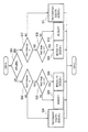
図3を参照して、図1の電源制御部4による絶縁型DCDCコンバータ3aの制御手順をの一例を説明する。図3の処理は、予め定めた周期で繰り返し実施されるものである。[Power supply control method]
With reference to FIG. 3, an example of the control procedure of the
先ず、ステップS01において、電源制御部4は、車両駆動用モータ6が回生動作を行っているのか、或いは、力行動作を行っているのかを判断する。例えば、第1電源電圧測定部12により測定された第1電源電圧Vbatが減少傾向にあれば、力行動作を行っていると判断し、第1電源電圧Vbatが増加傾向にあれば、回生動作を行っていると判断すればよい。これ以外にも、第1のインバータ5或いは車両駆動用モータ6から出力される、力行動作或いは回生動作を示す信号に基づいて判断しても構わない。
First, in step S01, the power supply control unit 4 determines whether the vehicle drive motor 6 is performing a regenerative operation or a powering operation. For example, if the first power supply voltage Vbat measured by the first power supply
力行動作を行っていると判断した場合、ステップS02へ進み、電源制御部4は、直流電圧測定部11により測定された直流電圧Vdcが、第1のインバータ5に入力可能な下限値Vdcminよりも大きいか否かを判断する。直流電圧Vdcが下限値Vdcminよりも大きくないと判断した場合(S02でNO)、ステップS04へ進み、電源制御部4は、直流電圧Vdcが下限値Vdcminよりも大きくなるように、絶縁型DCDCコンバータ3aを用いて第2電源2の第2電源電圧Vcapを制御する。例えば、電源制御部4は、絶縁型DCDCコンバータ3aをオン状態に制御して、一次側に接続された第1電源1aから二次側に接続された第2電源2へ電力を伝達する。これにより、第2電源2の第2電源電圧Vcapが上昇し、直流電圧Vdcも上昇して下限値Vdcminよりも大きくなる。
When it is determined that the power running operation is performed, the process proceeds to step S02, and the power supply control unit 4 determines that the DC voltage Vdc measured by the DC
直流電圧Vdcが下限値Vdcminよりも大きいと判断した場合(S02でYES)、ステップS03へ進み、電源制御部は4は、第1電源1aの第1電源電圧Vbatと第2電源2の第2電源電圧Vcapの比が、絶縁型DCDCコンバータ3aの一次側と二次側の変圧比(=X:Y)に等しいか否かを判断する。Vbat:VcapがX:Yに等しいと判断した場合(S03でYES)、ステップS06に進み、電源制御部4は、絶縁型DCDCコンバータ3aを用いて第2電源電圧Vcapを制御する。これにより、絶縁型DCDCコンバータ3aのスイッチング素子32a〜32d、34a〜34dをソフトスイッチング動作させることができるので、スイッチング損失が低減して力行効率が向上する。なお、第2電源電圧Vcapは、直流電圧Vdcから第1電源電圧Vbatを減じることにより求めることができる。
When it is determined that the DC voltage Vdc is larger than the lower limit value Vdcmin (YES in S02), the process proceeds to step S03, where the power supply control unit 4 determines the first power supply voltage Vbat of the
Vbat:VcapがX:Yに等しくないと判断した場合(S03でNO)、ステップS05に進み、電源制御部4は、絶縁型DCDCコンバータ3aをオフ状態に制御する。
When it is determined that Vbat: Vcap is not equal to X: Y (NO in S03), the process proceeds to step S05, and the power supply control unit 4 controls the
一方、車両駆動用モータ6が回生動作を行っていると判断した場合、ステップS07へ進み、電源制御部4は、直流電圧測定部11により測定された直流電圧Vdcが、第1のインバータ5に入力可能な上限値Vdcmaxよりも小さいか否かを判断する。直流電圧Vdcが上限値Vdcmaxよりも小さくないと判断した場合(S07でNO)、ステップS11へ進み、電源制御部4は、直流電圧Vdcが上限値Vdcmaxよりも小さくなるように、絶縁型DCDCコンバータ3aを用いて第2電源電圧Vcapを制御する。例えば、電源制御部4は、絶縁型DCDCコンバータ3aをオン状態に制御して、二次側に接続された第2電源2から一次側に接続された第1電源1aへ電力を伝達する。これにより、第2電源電圧Vcapが減少し、直流電圧Vdcも減少して上限値Vdcmaxよりも小さくなる。
On the other hand, if it is determined that the vehicle drive motor 6 is performing a regenerative operation, the process proceeds to step S07, and the power supply control unit 4 causes the DC voltage Vdc measured by the DC
直流電圧Vdcが上限値Vdcmaxよりも小さいと判断した場合(S07でYES)、ステップS08へ進み、電源制御部4は、上記したステップS03と同じ処理を実施する。Vbat:VcapがX:Yに等しいと判断した場合(S08でYES)、ステップS09に進み、電源制御部4は、上記したステップS06と同じ処理を実施する。これにより、絶縁型DCDCコンバータ3aのスイッチング素子32a〜32d、34a〜34dをソフトスイッチング動作させることができるので、スイッチング損失が低減して回生効率が向上する。
When it is determined that DC voltage Vdc is smaller than upper limit value Vdcmax (YES in S07), the process proceeds to step S08, and power supply control unit 4 performs the same process as step S03 described above. If it is determined that Vbat: Vcap is equal to X: Y (YES in S08), the process proceeds to step S09, and the power supply control unit 4 performs the same process as in step S06 described above. Thereby, since the
Vbat:VcapがX:Yに等しくないと判断した場合(S08でNO)、ステップS10に進み、電源制御部4は、絶縁型DCDCコンバータ3aをオフ状態に制御する。
When it is determined that Vbat: Vcap is not equal to X: Y (NO in S08), the process proceeds to step S10, and the power supply control unit 4 controls the
ステップS04〜S06、S09〜S11の後は再びステップS01に戻る。 After steps S04 to S06 and S09 to S11, the process returns to step S01 again.
図2を参照して、図3に示した電源制御部4による絶縁型DCDCコンバータ3aの制御手順による直流電圧Vdc及び第1電源電圧Vbatの時間変化の様子を説明する。
With reference to FIG. 2, how the DC voltage Vdc and the first power supply voltage Vbat change with time according to the control procedure of the
先ず、力行状態においては、直列に接続された第1電源1a及び第2電源2から出力される直流電圧Vdc、及び第1電源1aから出力される第1電源電圧Vbatは、時間の経過と共に減少する。直流電圧Vdcが下限値Vdcminよりも大きい場合、絶縁型DCDCコンバータ3aはオフ状態に制御される。すなわち、電源制御部4は、絶縁型DCDCコンバータ3aを用いて第2電源電圧Vcapを制御しない(図3のS05)。なお、図2中のS04〜S06、S09〜S11の表記は、図3のフローチャートにおける処理内容に対応している。
First, in the power running state, the DC voltage Vdc output from the
力行状態において、Vbat:VcapがX:Yに等しくなった時、電源制御部4は、絶縁型DCDCコンバータ3aをオン状態に切り替えることにより、絶縁型DCDCコンバータ3aを用いた第2電源電圧Vcapの制御を開始する(図3のS06)。
In the power running state, when Vbat: Vcap becomes equal to X: Y, the power supply control unit 4 switches the
直流電圧Vdcが下限値Vdcminに近づいてくると、電源制御部4は、直流電圧Vdcが下限値Vdcmin以下にならないように、絶縁型DCDCコンバータ3aを用いて第2電源電圧Vcapを制御する(図3のS04)。
When the DC voltage Vdc approaches the lower limit value Vdcmin, the power supply control unit 4 controls the second power supply voltage Vcap using the
次に、力行状態から回生状態へ移行すると、回生された電力は、直列に接続された第1電源1a及び第2電源2へそれぞれ充電されるので、直流電圧Vdc及び第1電源電圧Vbatが、時間の経過と共に上昇する。直流電圧Vdcが上限値Vdcmaxよりも小さい場合、絶縁型DCDCコンバータ3aはオフ状態に制御される。すなわち、電源制御部4は、絶縁型DCDCコンバータ3aを用いて第2電源電圧Vcapを制御しない(図3のS10)。
Next, when shifting from the power running state to the regenerative state, the regenerated electric power is charged to the
回生状態において、Vbat:VcapがX:Yに等しくなった時、電源制御部4は、絶縁型DCDCコンバータ3aをオン状態に切り替えることにより、絶縁型DCDCコンバータ3aを用いた第2電源電圧Vcapの制御を開始する(図3のS09)。
In the regenerative state, when Vbat: Vcap becomes equal to X: Y, the power supply control unit 4 switches the
直流電圧Vdcが上限値Vdcmaxに近づいてくると、電源制御部4は、直流電圧Vdcが上限値Vdcmax以上にならないように、絶縁型DCDCコンバータ3aを用いて第2電源電圧Vcapを制御する(図3のS11)。具体的には、二次側に接続された第2電源2から一次側に接続された第1電源1aへ電力を伝達する。これにより、第2電源電圧Vcapが減少し、直流電圧Vdcも減少して上限値Vdcmaxよりも小さくなる。
When the DC voltage Vdc approaches the upper limit value Vdcmax, the power supply control unit 4 controls the second power supply voltage Vcap using the
再び、回生状態から力行状態へ移行すると、上記した処理を繰り返し実行する。 When the state again shifts from the regenerative state to the power running state, the above-described processing is repeatedly executed.
以上説明したように、本発明の第1実施形態によれば、以下の作用効果が得られる。 As described above, according to the first embodiment of the present invention, the following operational effects can be obtained.
電力を充放電可能な第1電源1aと第2電源2とに直列に接続し、絶縁型DCDCコンバータ3aの一次側端子に第1電源1aを接続し、電源制御部4が、絶縁型DCDCコンバータ3aの二次側端子に第2電源2を接続して、絶縁型DCDCコンバータ3aを用いて第2電源2の電圧(第2電源電圧Vcap)を制御する。直列に接続された第1電源1a及び第2電源2から出力される直流電圧Vdcは、第1のインバータ5に入力され、第1のインバータ5により交流電圧に変換されてから車両駆動用モータ6へ供給される。第1電源1aの充電状態が低い時でも、絶縁型DCDCコンバータ3aを用いて第2電源電圧Vcapを制御することにより、直流電圧Vdcを高く維持することができる。よって、第1のインバータ5内で使用する半導体素子の電流容量を削減して、第1のインバータ5を小型化することができる。
A
車両駆動用モータ6により車両が力行する場合において、直流電圧Vdcが第1のインバータ5に入力可能な下限値Vdcminよりも大きければ、電源制御部4は、絶縁型DCDCコンバータ3aを用いて第2電源電圧Vcapを制御しない。力行状態において直流電圧Vdcが下限値Vdcminよりも大きければ、絶縁型DCDCコンバータ3aは動作しないので力行効率が向上する。
When the vehicle is powered by the vehicle drive motor 6, if the DC voltage Vdc is larger than the lower limit value Vdcmin that can be input to the
車両駆動用モータ6を用いて車両が力行する場合において、電源制御部4は、直流電圧Vdcが下限値Vdcminを下回らないように第2電源電圧Vcapを制御する。直流電圧Vdcの下限値Vdcminを保障して力行効率が向上する。 When the vehicle is powered using the vehicle driving motor 6, the power supply control unit 4 controls the second power supply voltage Vcap so that the DC voltage Vdc does not fall below the lower limit value Vdcmin. The power running efficiency is improved by ensuring the lower limit value Vdcmin of the DC voltage Vdc.
車両駆動用モータ6が電力を回生する場合において、直流電圧Vdcが第1のインバータ5に入力可能な上限値Vdcmaxよりも小さければ、電源制御部4は、絶縁型DCDCコンバータ3aを用いて第2電源電圧Vcapを制御しない。回生状態において直流電圧Vdcが上限値Vdcmaxよりも小さければ、絶縁型DCDCコンバータ3aは動作しないので回生効率が向上する。
When the vehicle drive motor 6 regenerates electric power, if the DC voltage Vdc is smaller than the upper limit value Vdcmax that can be input to the
車両駆動用モータ6が電力を回生する場合において、電源制御部4は、直流電圧Vdcが上限値Vdcmaxを上回らないように第2電源電圧Vcapを制御する。第1のインバータ5が備える半導体素子の破壊を抑制して動作安全性が向上する。
When the vehicle drive motor 6 regenerates electric power, the power supply control unit 4 controls the second power supply voltage Vcap so that the DC voltage Vdc does not exceed the upper limit value Vdcmax. Operational safety is improved by suppressing the destruction of the semiconductor element included in the
絶縁型DCDCコンバータ3aは、一次側と二次側の間の双方向に電力を伝達することができる双方向絶縁型DCDCコンバータである。双方向絶縁型DCDCコンバータは電力の変換効率が高いため、絶縁型DCDCコンバータ3aによる余計な電力消費を抑えて第2電源電圧Vcapの制御効率が向上する。
The insulation
絶縁型DCDCコンバータ3aの一次側と二次側の変圧比をX:Yとした場合、第1電源電圧Vbatと第2電源電圧Vcapの比がX:Yとなった時に、電源制御部4は、絶縁型DCDCコンバータ3aを用いた第2電源電圧Vcapの制御を開始する。絶縁型DCDCコンバータ3aをソフトスイッチングで動作させることができるので、絶縁型DCDCコンバータ3aによる余計な電力消費を抑えて第2電源電圧Vcapの制御効率が向上する。
When the transformation ratio between the primary side and the secondary side of the
第2電源2は静電容量素子であり、電源装置は、当該静電容量素子に対して並列に接続されたツェナーダイオード7を更に備える。絶縁型DCDCコンバータ3aがオープンモードで故障した時に静電容量素子に過電圧が加わることを抑制して安全性を向上させることができる。
The
(第2実施形態)
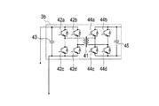
図4を参照して、第2実施形態に係わる絶縁型DCDCコンバータ3bの構成を説明する。第1実施形態では、図1に示したように、スイッチング素子32a〜32d、34a〜34dとして、MOS型電界効果トランジスタを用いた絶縁型DCDCコンバータ3aを例示した。しかし、スイッチング素子32a〜32d、34a〜34dは、MOS型電界効果トランジスタに限ることなく、例えば、バイポーラトランジスタを用いても構わない。図4に示すように、第2実施形態に係わる電源装置は、スイッチング素子42a〜42d、44a〜44dとして、バイポーラトランジスタを用いた絶縁型DCDCコンバータ3bを備える。更に、絶縁型DCDCコンバータ3bは、絶縁型DCDCコンバータ3aに比べて、更に二次側の平滑コンデンサ45を備える点が相違する。その他、一次側及び二次側のフルブリッジ回路の構成、絶縁型トランス41の変圧比については第1実施形態と同じであり説明を省略する。(Second Embodiment)
With reference to FIG. 4, the structure of the insulation
(第3実施形態)
図5に示すように、第3実施形態に係わる絶縁型DCDCコンバータ3cは、絶縁型トランス41の一次側に共振キャパシタ46が接続された構成を有する。一次側のスイッチング素子42a〜42dのソフトスイッチング動作が可能となり、スイッチング損失を軽減することができる。その他の点は、図4と同じであり説明を省略する。(Third embodiment)
As shown in FIG. 5, the
(第4実施形態)
図6を参照して、第4実施形態に係わる電源装置の構成を説明する。第4実施形態に係わる電源装置は、図1に示した電源装置に比して、直流側端子が第1電源1bに接続された第2のインバータ8と、第2のインバータ8の交流側端子が接続された発電機9と、を更に備える点が相違する。その他の構成は同じであり説明を省略する。(Fourth embodiment)
With reference to FIG. 6, the structure of the power supply device concerning 4th Embodiment is demonstrated. Compared with the power supply apparatus shown in FIG. 1, the power supply apparatus according to the fourth embodiment includes a second inverter 8 having a DC side terminal connected to the
第1電源1bは、リチウム(Li)イオンバッテリーなどの電池ではなく、電気2重層キャパシタ、Liイオンキャパシタ、コンデンサなどの静電容量素子からなる。電源制御部4は、第1電源電圧Vbatから第1電源1bの充電状態をモニターする。第1電源1bの充電状態が低下した場合に、発電機9を動作させ、発生した交流電力を第2のインバータ8で直流電電力へ変換し、第1電源1bを充電する。このように、発電機9が発電する電力を第2のインバータ8を介して第1電源1bに供給することにより、第1電源1bの充電状態の低下を抑制して、第1のインバータ5に入力される直流電圧Vdcを高く維持することができる。
The
特願2012−037636号(出願日:2012年2月23日)の全内容は、ここに援用される。 The entire contents of Japanese Patent Application No. 2012-037636 (filing date: February 23, 2012) are incorporated herein by reference.
以上、実施例に沿って本発明の内容を説明したが、本発明はこれらの記載に限定されるものではなく、種々の変形及び改良が可能であることは、当業者には自明である。 Although the contents of the present invention have been described with reference to the embodiments, the present invention is not limited to these descriptions, and it is obvious to those skilled in the art that various modifications and improvements can be made.
本実施形態に係わる電源装置によれば、第1のインバータ5に入力される直流電圧を高く維持できるので、第1のインバータ5内で使用する半導体素子の電流容量を削減して第1のインバータ5を小型化することができる。よって、本発明は、産業上の利用可能性を有する。
According to the power supply device according to the present embodiment, since the DC voltage input to the
Vbat…第1電源電圧
Vcap…第2電源電圧
Vdc…直流電圧
Vdcmax…上限値
Vdcmin…下限値
1a、1b…第1電源
2…第2電源
3a〜3c…絶縁型DCDCコンバータ
4…電源制御部
5…第1のインバータ
6…車両駆動用モータ
7…ツェナーダイオード
8…第2のインバータ
9…発電機Vbat ... 1st power supply voltage Vcap ... 2nd power supply voltage Vdc ... DC voltage Vdcmax ... Upper limit value Vdcmin ...
Claims (10)
前記第1電源に直列に接続された、電力を充放電可能な第2電源と、
一次側端子に前記第1電源が接続され、二次側端子に前記第2電源が接続された絶縁型DCDCコンバータと、
前記絶縁型DCDCコンバータを用いて前記第2電源の電圧を制御する電源制御部と、
を備え、
直列に接続された前記第1電源及び前記第2電源から出力される直流電圧は、第1のインバータに入力され、前記第1のインバータにより交流電圧に変換されてから車両駆動用モータへ供給され、
前記車両駆動用モータにより車両が力行する場合において、前記直流電圧が前記第1のインバータに入力可能な下限値よりも大きければ、前記電源制御部は、前記絶縁型DCDCコンバータを用いて前記第2電源の電圧を制御しない
ことを特徴とする電源装置。 A first power source capable of charging and discharging power;
A second power source connected in series to the first power source and capable of charging and discharging power;
An isolated DCDC converter in which the first power source is connected to a primary side terminal and the second power source is connected to a secondary side terminal;
A power supply control unit for controlling the voltage of the second power supply using the isolated DCDC converter;
With
The DC voltage output from the first power supply and the second power supply connected in series is input to a first inverter, converted into an AC voltage by the first inverter, and then supplied to the vehicle drive motor. ,
When the vehicle is powered by the vehicle drive motor and the DC voltage is greater than a lower limit value that can be input to the first inverter, the power supply control unit uses the isolated DCDC converter to perform the second operation. A power supply apparatus characterized by not controlling the voltage of the power supply.
前記第1電源に直列に接続された、電力を充放電可能な第2電源と、
一次側端子に前記第1電源が接続され、二次側端子に前記第2電源が接続された絶縁型DCDCコンバータと、
前記絶縁型DCDCコンバータを用いて前記第2電源の電圧を制御する電源制御部と、
を備え、
直列に接続された前記第1電源及び前記第2電源から出力される直流電圧は、第1のインバータに入力され、前記第1のインバータにより交流電圧に変換されてから車両駆動用モータへ供給され、
前記車両駆動用モータが電力を回生する場合において、前記直流電圧が前記第1のインバータに入力可能な上限値よりも小さければ、前記電源制御部は、前記絶縁型DCDCコンバータを用いて前記第2電源の電圧を制御しない
ことを特徴とする電源装置。 A first power source capable of charging and discharging power;
A second power source connected in series to the first power source and capable of charging and discharging power;
An isolated DCDC converter in which the first power source is connected to a primary side terminal and the second power source is connected to a secondary side terminal;
A power supply control unit for controlling the voltage of the second power supply using the isolated DCDC converter;
With
The DC voltage output from the first power supply and the second power supply connected in series is input to a first inverter, converted into an AC voltage by the first inverter, and then supplied to the vehicle drive motor. ,
In the case where the vehicle drive motor regenerates electric power, if the DC voltage is smaller than an upper limit value that can be input to the first inverter, the power supply control unit uses the isolated DCDC converter to perform the second operation. A power supply apparatus characterized by not controlling the voltage of the power supply.
当該静電容量素子に対して並列に接続されたツェナーダイオードを更に備える
ことを特徴とする請求項1〜6のいずれか一項に記載の電源装置。 The second power source is a capacitive element;
The power supply device according to any one of claims 1 to 6, further comprising a Zener diode connected in parallel to the capacitive element.
前記第2のインバータの交流側端子が接続された発電機と、
を更に備えることを特徴とする請求項1〜7のいずれか一項に記載の電源装置。 A second inverter having a DC terminal connected to the first power source;
A generator connected to the AC side terminal of the second inverter;
The power supply device according to any one of claims 1 to 7, further comprising a.
前記絶縁型DCDCコンバータを用いて前記第2電源の電圧を制御し、
前記車両駆動用モータにより車両が力行する場合において、前記直流電圧が前記第1のインバータに入力可能な下限値よりも大きければ、前記絶縁型DCDCコンバータを用いて前記第2電源の電圧を制御しない
ことを特徴とする電源装置の制御方法。 A first power source capable of charging / discharging power, a second power source connected in series to the first power source, and capable of charging / discharging power, the first power source connected to a primary side terminal, and a secondary side terminal A DC voltage output from the first power source and the second power source connected in series, and input to the first inverter; A method of controlling a power supply device that is converted into an AC voltage by an inverter and then supplied to a vehicle drive motor,
Controlling the voltage of the second power source using the isolated DCDC converter;
When the vehicle is powered by the vehicle drive motor, the voltage of the second power supply is not controlled using the insulated DCDC converter if the DC voltage is greater than a lower limit value that can be input to the first inverter. A control method for a power supply device.
前記絶縁型DCDCコンバータを用いて前記第2電源の電圧を制御し、
前記車両駆動用モータが電力を回生する場合において、前記直流電圧が前記第1のインバータに入力可能な上限値よりも小さければ、前記絶縁型DCDCコンバータを用いて前記第2電源の電圧を制御しない
ことを特徴とする電源装置の制御方法。 A first power source capable of charging / discharging power, a second power source connected in series to the first power source, and capable of charging / discharging power, the first power source connected to a primary side terminal, and a secondary side terminal A DC voltage output from the first power source and the second power source connected in series, and input to the first inverter; A method of controlling a power supply device that is converted into an AC voltage by an inverter and then supplied to a vehicle drive motor,
Controlling the voltage of the second power source using the isolated DCDC converter;
When the vehicle drive motor regenerates electric power, if the DC voltage is smaller than an upper limit value that can be input to the first inverter, the voltage of the second power source is not controlled using the isolated DCDC converter. A control method for a power supply device.
Priority Applications (1)
| Application Number | Priority Date | Filing Date | Title |
|---|---|---|---|
| JP2014500943A JP5759060B2 (en) | 2012-02-23 | 2013-02-22 | Power supply device and control method thereof |
Applications Claiming Priority (4)
| Application Number | Priority Date | Filing Date | Title |
|---|---|---|---|
| JP2012037636 | 2012-02-23 | ||
| JP2012037636 | 2012-02-23 | ||
| JP2014500943A JP5759060B2 (en) | 2012-02-23 | 2013-02-22 | Power supply device and control method thereof |
| PCT/JP2013/054471 WO2013125672A1 (en) | 2012-02-23 | 2013-02-22 | Power-supply device and control method therefor |
Publications (2)
| Publication Number | Publication Date |
|---|---|
| JPWO2013125672A1 JPWO2013125672A1 (en) | 2015-07-30 |
| JP5759060B2 true JP5759060B2 (en) | 2015-08-05 |
Family
ID=49005849
Family Applications (1)
| Application Number | Title | Priority Date | Filing Date |
|---|---|---|---|
| JP2014500943A Active JP5759060B2 (en) | 2012-02-23 | 2013-02-22 | Power supply device and control method thereof |
Country Status (5)
| Country | Link |
|---|---|
| US (1) | US9559620B2 (en) |
| EP (1) | EP2819291B1 (en) |
| JP (1) | JP5759060B2 (en) |
| CN (1) | CN104145411B (en) |
| WO (1) | WO2013125672A1 (en) |
Families Citing this family (14)
| Publication number | Priority date | Publication date | Assignee | Title |
|---|---|---|---|---|
| CN104838573B (en) * | 2012-12-04 | 2017-07-28 | 沃尔沃卡车公司 | Supply unit |
| JP2014115882A (en) * | 2012-12-11 | 2014-06-26 | Denso Corp | Vehicle mounted emergency reporting system |
| JP5812040B2 (en) * | 2013-05-21 | 2015-11-11 | トヨタ自動車株式会社 | Power converter |
| CN103490614A (en) * | 2013-09-13 | 2014-01-01 | 嘉兴凯希电子有限公司 | Maximum-power tracker |
| JP5928519B2 (en) * | 2014-04-09 | 2016-06-01 | トヨタ自動車株式会社 | Power conversion device and power conversion method |
| US9809119B2 (en) * | 2015-01-13 | 2017-11-07 | General Electric Company | Bi-directional DC-DC power converter for a vehicle system |
| CN105790628B (en) * | 2016-03-29 | 2018-04-10 | 浙江大学 | A kind of switched reluctance motor system based on function integrated converter |
| US9960687B2 (en) * | 2016-06-06 | 2018-05-01 | General Electric Company | System and method for a DC/DC converter |
| US9851770B1 (en) | 2017-01-08 | 2017-12-26 | ANEWCOM, Inc. | Network devices with multi-level electrical isolation |
| WO2019076874A1 (en) * | 2017-10-16 | 2019-04-25 | Danmarks Tekniske Universitet | A dc-dc converter assembly |
| EP3670239A1 (en) * | 2018-12-20 | 2020-06-24 | Vitesco Technologies GmbH | Power supply network and hybrid vehicle |
| EP4236048A3 (en) | 2019-05-24 | 2023-10-25 | Huawei Digital Power Technologies Co., Ltd. | Integrated charger and motor control system comprising a transformer and multi-level power converters |
| CN110829850B (en) * | 2019-11-14 | 2021-11-26 | 中车永济电机有限公司 | Vehicle-mounted converter circuit and control method thereof |
| DE102020131537A1 (en) | 2020-11-27 | 2022-06-02 | ACD Antriebstechnik GmbH | Energy storage with current source switching |
Family Cites Families (13)
| Publication number | Priority date | Publication date | Assignee | Title |
|---|---|---|---|---|
| JPH0956167A (en) * | 1995-08-11 | 1997-02-25 | Denso Corp | Motor controller |
| JP3746334B2 (en) * | 1996-08-22 | 2006-02-15 | トヨタ自動車株式会社 | Permanent magnet type synchronous motor drive control apparatus and method |
| JPH10164862A (en) * | 1996-12-02 | 1998-06-19 | Toshiba Corp | Power conversion apparatus |
| DE19921450C5 (en) * | 1999-05-08 | 2006-08-03 | Daimlerchrysler Ag | Electric vehicle drive |
| JP2002330545A (en) | 2001-04-27 | 2002-11-15 | Nissan Motor Co Ltd | Power unit |
| JP3931734B2 (en) * | 2002-06-05 | 2007-06-20 | トヨタ自動車株式会社 | Electric load drive |
| JP3885771B2 (en) * | 2003-06-24 | 2007-02-28 | 株式会社デンソー | Power system |
| JP4797476B2 (en) * | 2005-07-12 | 2011-10-19 | トヨタ自動車株式会社 | Secondary battery control device |
| DE112008000422T5 (en) * | 2007-02-16 | 2009-12-03 | Komatsu Ltd. | Voltage control device and voltage control method |
| US8080973B2 (en) * | 2008-10-22 | 2011-12-20 | General Electric Company | Apparatus for energy transfer using converter and method of manufacturing same |
| JP4977165B2 (en) * | 2009-04-01 | 2012-07-18 | トヨタ自動車株式会社 | Noise reduction structure for 3-phase brushless motor |
| CN102362419B (en) * | 2009-04-03 | 2014-03-12 | 株式会社小松制作所 | Control device for transformer coupling type booster |
| JP2012037636A (en) | 2010-08-05 | 2012-02-23 | Seiko Epson Corp | Projector and control method thereof |
-
2013
- 2013-02-22 JP JP2014500943A patent/JP5759060B2/en active Active
- 2013-02-22 EP EP13751598.7A patent/EP2819291B1/en active Active
- 2013-02-22 CN CN201380010558.1A patent/CN104145411B/en active Active
- 2013-02-22 US US14/379,656 patent/US9559620B2/en active Active
- 2013-02-22 WO PCT/JP2013/054471 patent/WO2013125672A1/en active Application Filing
Also Published As
| Publication number | Publication date |
|---|---|
| US20150002057A1 (en) | 2015-01-01 |
| CN104145411A (en) | 2014-11-12 |
| CN104145411B (en) | 2016-12-07 |
| WO2013125672A1 (en) | 2013-08-29 |
| US9559620B2 (en) | 2017-01-31 |
| EP2819291A4 (en) | 2015-12-30 |
| EP2819291B1 (en) | 2017-05-10 |
| EP2819291A1 (en) | 2014-12-31 |
| JPWO2013125672A1 (en) | 2015-07-30 |
Similar Documents
| Publication | Publication Date | Title |
|---|---|---|
| JP5759060B2 (en) | Power supply device and control method thereof | |
| US9616760B2 (en) | Inverter-charger integrated device for electric vehicle | |
| JP5874990B2 (en) | Motor drive device | |
| JP6736370B2 (en) | Power conversion system | |
| JP5453232B2 (en) | Electric vehicle | |
| WO2013129231A1 (en) | Power supply apparatus | |
| JP6736369B2 (en) | Power conversion system | |
| JP6708259B2 (en) | Power system | |
| JP2016019463A (en) | Pulse width modulation resonant converter, and vehicle charger utilizing the same | |
| WO2015004948A1 (en) | Discharge control device | |
| JP5680050B2 (en) | Charger | |
| KR100999969B1 (en) | Apparatus for charging battery | |
| JP2013038910A (en) | Power supply system and vehicle including the same | |
| KR20150080917A (en) | Electricity supply system having double power-storage devices of a hybrid or electric motor vehicle | |
| JP2020108260A (en) | Charging device and vehicle | |
| JP2020005389A (en) | Power supply system | |
| WO2011004588A1 (en) | Electric vehicle control device | |
| JP5358309B2 (en) | Multifunctional converter for vehicles | |
| US11097620B2 (en) | Circuit system for railroad vehicle | |
| Bai et al. | The impact of bidirectional DC-DC converter on the inverter operation and battery current in hybrid electric vehicles | |
| JP2011091889A (en) | Charging device | |
| JP5540872B2 (en) | Power supply | |
| JP2013027236A (en) | Battery charging system and vehicle charging system | |
| JP5069363B1 (en) | Charger | |
| JP2011244656A (en) | Dc-dc converter |
Legal Events
| Date | Code | Title | Description |
|---|---|---|---|
| TRDD | Decision of grant or rejection written | ||
| A01 | Written decision to grant a patent or to grant a registration (utility model) |
Free format text: JAPANESE INTERMEDIATE CODE: A01 Effective date: 20150519 |
|
| A61 | First payment of annual fees (during grant procedure) |
Free format text: JAPANESE INTERMEDIATE CODE: A61 Effective date: 20150604 |
|
| R150 | Certificate of patent or registration of utility model |
Ref document number: 5759060 Country of ref document: JP Free format text: JAPANESE INTERMEDIATE CODE: R150 |