JP5758424B2 - lighting equipment - Google Patents
lighting equipment Download PDFInfo
- Publication number
- JP5758424B2 JP5758424B2 JP2013040922A JP2013040922A JP5758424B2 JP 5758424 B2 JP5758424 B2 JP 5758424B2 JP 2013040922 A JP2013040922 A JP 2013040922A JP 2013040922 A JP2013040922 A JP 2013040922A JP 5758424 B2 JP5758424 B2 JP 5758424B2
- Authority
- JP
- Japan
- Prior art keywords
- power supply
- radiator
- supply case
- heat
- projector
- Prior art date
- Legal status (The legal status is an assumption and is not a legal conclusion. Google has not performed a legal analysis and makes no representation as to the accuracy of the status listed.)
- Active
Links
Images


Classifications
-
- F—MECHANICAL ENGINEERING; LIGHTING; HEATING; WEAPONS; BLASTING
- F21—LIGHTING
- F21V—FUNCTIONAL FEATURES OR DETAILS OF LIGHTING DEVICES OR SYSTEMS THEREOF; STRUCTURAL COMBINATIONS OF LIGHTING DEVICES WITH OTHER ARTICLES, NOT OTHERWISE PROVIDED FOR
- F21V21/00—Supporting, suspending, or attaching arrangements for lighting devices; Hand grips
- F21V21/14—Adjustable mountings
- F21V21/30—Pivoted housings or frames
-
- F—MECHANICAL ENGINEERING; LIGHTING; HEATING; WEAPONS; BLASTING
- F21—LIGHTING
- F21V—FUNCTIONAL FEATURES OR DETAILS OF LIGHTING DEVICES OR SYSTEMS THEREOF; STRUCTURAL COMBINATIONS OF LIGHTING DEVICES WITH OTHER ARTICLES, NOT OTHERWISE PROVIDED FOR
- F21V23/00—Arrangement of electric circuit elements in or on lighting devices
- F21V23/003—Arrangement of electric circuit elements in or on lighting devices the elements being electronics drivers or controllers for operating the light source, e.g. for a LED array
- F21V23/007—Arrangement of electric circuit elements in or on lighting devices the elements being electronics drivers or controllers for operating the light source, e.g. for a LED array enclosed in a casing
- F21V23/008—Arrangement of electric circuit elements in or on lighting devices the elements being electronics drivers or controllers for operating the light source, e.g. for a LED array enclosed in a casing the casing being outside the housing of the lighting device
-
- F—MECHANICAL ENGINEERING; LIGHTING; HEATING; WEAPONS; BLASTING
- F21—LIGHTING
- F21V—FUNCTIONAL FEATURES OR DETAILS OF LIGHTING DEVICES OR SYSTEMS THEREOF; STRUCTURAL COMBINATIONS OF LIGHTING DEVICES WITH OTHER ARTICLES, NOT OTHERWISE PROVIDED FOR
- F21V29/00—Protecting lighting devices from thermal damage; Cooling or heating arrangements specially adapted for lighting devices or systems
- F21V29/50—Cooling arrangements
- F21V29/502—Cooling arrangements characterised by the adaptation for cooling of specific components
- F21V29/507—Cooling arrangements characterised by the adaptation for cooling of specific components of means for protecting lighting devices from damage, e.g. housings
-
- F—MECHANICAL ENGINEERING; LIGHTING; HEATING; WEAPONS; BLASTING
- F21—LIGHTING
- F21S—NON-PORTABLE LIGHTING DEVICES; SYSTEMS THEREOF; VEHICLE LIGHTING DEVICES SPECIALLY ADAPTED FOR VEHICLE EXTERIORS
- F21S8/00—Lighting devices intended for fixed installation
- F21S8/03—Lighting devices intended for fixed installation of surface-mounted type
- F21S8/033—Lighting devices intended for fixed installation of surface-mounted type the surface being a wall or like vertical structure, e.g. building facade
- F21S8/036—Lighting devices intended for fixed installation of surface-mounted type the surface being a wall or like vertical structure, e.g. building facade by means of a rigid support, e.g. bracket or arm
-
- F—MECHANICAL ENGINEERING; LIGHTING; HEATING; WEAPONS; BLASTING
- F21—LIGHTING
- F21W—INDEXING SCHEME ASSOCIATED WITH SUBCLASSES F21K, F21L, F21S and F21V, RELATING TO USES OR APPLICATIONS OF LIGHTING DEVICES OR SYSTEMS
- F21W2131/00—Use or application of lighting devices or systems not provided for in codes F21W2102/00-F21W2121/00
- F21W2131/10—Outdoor lighting
-
- F—MECHANICAL ENGINEERING; LIGHTING; HEATING; WEAPONS; BLASTING
- F21—LIGHTING
- F21Y—INDEXING SCHEME ASSOCIATED WITH SUBCLASSES F21K, F21L, F21S and F21V, RELATING TO THE FORM OR THE KIND OF THE LIGHT SOURCES OR OF THE COLOUR OF THE LIGHT EMITTED
- F21Y2105/00—Planar light sources
- F21Y2105/10—Planar light sources comprising a two-dimensional array of point-like light-generating elements
-
- F—MECHANICAL ENGINEERING; LIGHTING; HEATING; WEAPONS; BLASTING
- F21—LIGHTING
- F21Y—INDEXING SCHEME ASSOCIATED WITH SUBCLASSES F21K, F21L, F21S and F21V, RELATING TO THE FORM OR THE KIND OF THE LIGHT SOURCES OR OF THE COLOUR OF THE LIGHT EMITTED
- F21Y2115/00—Light-generating elements of semiconductor light sources
- F21Y2115/10—Light-emitting diodes [LED]
Description
本発明は、発光素子を光源とする照明器具に関する。 The present invention relates to a lighting fixture using a light emitting element as a light source.
従来、発光素子たる複数のLEDを光源に備えた照明器具が知られている。この種の照明器具では、LEDを収めた光源ケースと、電源回路を収めた電源ケースとを一体に形成した照明器具本体を備えたものが知られている(例えば、特許文献1参照)。 2. Description of the Related Art Conventionally, lighting fixtures that include a plurality of LEDs as light emitting elements in a light source are known. In this type of lighting fixture, there is known a lighting fixture including a lighting fixture body in which a light source case containing an LED and a power supply case containing a power supply circuit are integrally formed (see, for example, Patent Document 1).
しかしながら、光源ケースと電源ケースを一体に照明器具本体として構成した場合、光源ケースと電源ケースとが熱的に結合し、例えば電源ケースにあっては、LEDの熱が伝熱し電源回路に熱的損傷が生じる等の問題がある。 However, when the light source case and the power supply case are integrally configured as a lighting fixture main body, the light source case and the power supply case are thermally coupled. For example, in the power supply case, the heat of the LED is transferred to the power supply circuit. There are problems such as damage.
本発明は、上述した事情に鑑みてなされたものであり、光源ケースと電源ケースの間の熱的な影響を抑えることができる照明器具を提供することを目的とする。 This invention is made | formed in view of the situation mentioned above, and aims at providing the lighting fixture which can suppress the thermal influence between a light source case and a power supply case.
上記目的を達成するために、本発明は、発光素子を収め、当該発光素子の光を放射する開口を前面に有し、外表面には放熱フィンを備えた放熱体と、前記発光素子の電源回路を収納し、外表面に放熱フィンを備えた電源ケースと、前記電源ケースに設けられた取付アームと、を備え、前記電源ケースは、前記放熱体からみて前記取付アームが延びる側に前記放熱体の放熱フィンとの間に空間をあけて設けられ、前記放熱体から連続し、背面の側に斜めに延びて設けられていることを特徴とする照明器具を提供する。 In order to achieve the above object, the present invention includes a radiator that houses a light-emitting element, has an opening for radiating light of the light-emitting element, and has a heat-radiating fin on the outer surface, and a power source for the light-emitting element. A power supply case that houses a circuit and has heat radiation fins on an outer surface; and a mounting arm provided on the power supply case, wherein the power supply case is arranged on the side where the mounting arm extends as viewed from the heat radiator. Provided is a lighting fixture which is provided with a space between the heat dissipating fins of the body, is provided continuously from the heat dissipating body , and extends obliquely on the back side .
また本発明は、上記照明器具において、狭角配光を形成する凹状の反射鏡が前記発光素子を囲うように前記放熱体に設けられ、当該反射鏡の先端部を前記放熱体の前面の開口から突出させ、当該放熱体の背面の側に向かって斜めに延びるように前記電源ケースを設けたことを特徴とする。
本発明は、上記照明器具において、前記放熱体の底面は器具光軸と略平行であり、前記電源ケースは、前記底面に対して略45度の角度で延びていることを特徴とする。
According to the present invention, in the lighting apparatus, a concave reflecting mirror that forms a narrow-angle light distribution is provided in the radiator so as to surround the light emitting element, and a front end portion of the reflecting mirror is opened at a front surface of the radiator. And the power supply case is provided so as to extend obliquely toward the back side of the radiator.
The present invention is characterized in that, in the above-described lighting fixture, the bottom surface of the radiator is substantially parallel to the optical axis of the fixture, and the power supply case extends at an angle of about 45 degrees with respect to the bottom surface.
また本発明は、上記照明器具において、前記放熱体は、互いに異なる角度で形成された前記放熱フィンを備えていることを特徴とする。 Moreover, the present invention is characterized in that, in the above-mentioned lighting fixture, the heat radiating body includes the heat radiating fins formed at different angles.
また本発明は、上記照明器具において、前記放熱体の前記前面の開口を覆うグローブを備えることを特徴とする。 Moreover, this invention is equipped with the glove | cover which covers the opening of the said front surface of the said heat radiator in the said lighting fixture.
本発明の照明器具によれば、発光素子の熱を放熱する放熱体の放熱フィンと空間をあけて電源ケースが取付けられているので、放熱体と電源ケースの熱的な結合が弱められ、両者の間の熱的な影響が抑えられる。これにより、照明器具の小型化・軽量化につながり、また放熱効率が向上したことで、低ワット化・省エネに繋がる。 According to the lighting apparatus of the present invention, since the power supply case is attached with a space between the heat dissipating fins of the heat dissipating element that dissipates heat from the light emitting element, the thermal coupling between the heat dissipating element and the power supply case is weakened The thermal effect during the period is suppressed. This leads to smaller and lighter lighting fixtures and improved heat dissipation efficiency, leading to lower wattage and energy savings.
以下、本発明の実施形態について図面を参照して説明する。なお、以下では、照明器具の一態様である投光器を例にして本発明を説明する。
[第1実施形態]
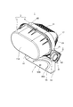
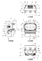
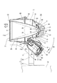
図1は本発明の第1実施形態に係る投光器1の斜視図である。図2は投光器1の構成図であり、図2(A)は正面図、図2(B)は平面図、図2(C)は底面図、図2(D)は側面図である。図3は投光器1の背面図であり、図4は図2(A)のIV−IV矢視断面図である。図5は図2(A)のV−V矢視断面図である。
本実施形態の投光器1は、屋外に設置されて、数十〜数百メートル離れた遠方を照明する照明器具である。この投光器1の配光は、1/2ビーム角が5〜8度ほどの狭角配光であり、遠方での照射スポット径の拡がりが抑えられることで、当該遠方での照度が高められている。
Embodiments of the present invention will be described below with reference to the drawings. In the following, the present invention will be described with reference to an example of a projector that is one embodiment of a lighting fixture.
[First Embodiment]
FIG. 1 is a perspective view of a
The
図1〜図4に示すように、この投光器1は、光源を収めた器具本体としての投光器本体3と、光源に電力を供給する電源ケース5と、投光器本体3を設置箇所に取り付けるための取付アーム7とを備えている。
投光器本体3は、光源を収めるケース体としての機能、及び放熱機能を備えた放熱体9と、この放熱体9の前面を覆う前面カバー11(グローブ)とを備えている。
放熱体9は、高い熱伝導性を有する材料を用いたダイキャスト成形等で形成されており、外表面に多数の垂直放熱フィン21、及び水平放熱フィン23が一体に形成され、その内部には、図4に示すように、光源としての複数のLEDモジュール25、及び光学素子としての複数の反射鏡26が収められている。
As shown in FIGS. 1 to 4, the
The projector
The
反射鏡26は、略回転放物面形状に形成され、その内面は回転放物反射面32に形成されている。この投光器1では、図2(A)に示すように、放熱体9には、2つの反射鏡26が横並びに収められている。このため、放熱体9は正面視では、2つの反射鏡26が収められる程度の横長楕円形に形成され、平面視、及び側面視では、図1、図2(B)及び、図2(D)に示すように、正面側から背面側にかけて、反射鏡26の縮径に合わせるように、横幅、及び縦幅が次第に狭められた形状の椀状に形成されている。
The reflecting
放熱体9の内部の底(以下、「内底」と言う)9Aは、正面視略矩形の平らな面に形成されており、この内底9AにLEDモジュール25が配置されている。このLEDモジュール25は、図2(A)に示すように、横長矩形のLED実装基板31を有し、実装面31Aには、光源たる発光素子としての2つのLEDパッケージ29が設けられている。そして、LEDパッケージ29のそれぞれごとに、上記反射鏡26が設けられている。
すなわち、反射鏡26の基端部側には、光軸Kに対応する箇所に開口35が設けられており、この開口35からLEDパッケージ29の発光部30を内部に導入するように反射鏡26が設けられている。反射鏡26の中において、発光部30は、回転放物反射面32の略焦点位置に配置され、これにより、発光部30の光が回転放物反射面32によって略平行光化されて放射されることとなる。
An inner bottom (hereinafter referred to as “inner bottom”) 9A of the
That is, an
反射鏡26の回転放物反射面32は、上述の通り、1/2ビーム角が5〜8度ほどの狭角配光を得るものであり、このような配光を得るために、通常の回転放物面鏡に比べ、開口端の径に対し回転中心軸(光軸K)に沿った全長が比較的長く形成されている。
詳述すると、反射鏡26から放射される光には、回転放物反射面32での反射で平行光化された反射光成分と、回転放物反射面32に入射せずに直接出射された直接光成分とが含まれる。この直接光成分は、所定の拡がり角で拡がる光であり、その拡がり角の最大角θ1は、発光部30から先端開口33の縁に向かう光の照射方向と、光軸Kとが成す角によって概ね規定される。
As described above, the rotary parabolic reflecting
More specifically, the light emitted from the reflecting
すなわち、回転放物反射面32の全長が短いほど、最大角θ1が大きくなることから、反射鏡26から放射される光の1/2ビーム角は大きくなる。そこで、この回転放物反射面32では、回転放物反射面32の全長を延ばして最大角θ1を小さくすることで、1/2ビーム角を5〜8度の小さな値に収めるようにしている。
また、回転放物反射面32の全長が延びることで、反射鏡26の放射光に占める反射光の成分が増え、直接光成分が少なくなる。このように直接光成分が少なくなることで、回転放物反射面32による制御を受けていない光成分、すなわち非平行成分が少なくなるため、照射スポットの輪郭のボケが抑えられる。
That is, as the total length of the rotary
Further, since the entire length of the rotary
このように全長が長い反射鏡26は、放熱体9に、その全長の全てが収められるのではなく、その基端部側から中程(中間地点)までが収められ、この放熱体9の前面の開口10からは反射鏡26の中程(中間地点)から先端までを突出させている。
前面カバー11は、放熱体9の開口端9Bに装着され、開口10から突出した反射鏡26を覆う透明樹脂製の略筒状の部材である。図4に示すように、反射鏡26の先端開口26Aは、前面カバー11の裏面に近接し、反射鏡26の先端開口33から出射される光は、その径を殆ど変わらない状態で前面カバー11の正面11Aに入射し、当該前面カバー11の正面11Aから出射される。すなわち、この前面カバー11の正面11Aが投光器1の出射面と見なすこともできる。
In this way, the reflecting
The
ここで、この投光器1は、遠方を高い照度でスポット照明可能にすべく、LEDパッケージ29には高出力型のものが用いられている。
図6は、係るLEDパッケージ29を備えたLEDモジュール25の平面図である。
LEDパッケージ29は、多数のLED27(発光素子)を密集配置したチップオンボード(COB)構造のパッケージであり、正面視略四角形形(円形も有り得る)の面状の発光部30を有している。
一般に、COB構造のLEDパッケージ29は、多数のLED27が密集配置されていることから大光量で輝度が高く、さらに、これらのLED27を最大出力で点灯駆動したときの発光効率の低下が小さい。したがって、このLEDパッケージ29を投光器1の光源とすることで、大光量を高発光効率で得られることとなる。
Here, the
FIG. 6 is a plan view of the
The
In general, the
ただし、係るLEDパッケージ29は発熱量も大きい。そこで、このLEDモジュール25では、絶縁性が高く、かつ高熱伝導性のセラミック基板が上記LED実装基板31に用いられている。さらに、この投光器1では、このLED実装基板31を放熱体9の内底9Aに接触させて配置することで、LEDパッケージ29の熱を放熱体9に効率良く伝熱させることとしている。
However, the
放熱体9の外表面には、上記の通り、多数の垂直放熱フィン21、及び水平放熱フィン23が一体に形成されており、LEDパッケージ29から放熱体9に伝えられた熱は、これら垂直放熱フィン21、及び水平放熱フィン23から空気中に放熱される。
垂直放熱フィン21は、図2(D)、及び図3に示すように、放熱体9の上面15から背面12、及び底面13にかけて延びた多数のフィンを幅方向に並設したものである。これら垂直放熱フィン21の各フィンは、鉛直方向に立設することで、図3の矢印Aで示すように、底面13の熱気が垂直放熱フィン21の間の隙間を伝って上昇し、背面12の側にスムーズに導かれる。これにより、底面13の側に熱気が籠もることがなく、底面13の側での放熱性能の低下が防止される。
As described above, a large number of
As shown in FIGS. 2D and 3, the vertical
ただし、屋外照明においては、この投光器1が放熱体9の側面17を地面側に向けて、垂直に立てた状態で設置され、使用される場合もある。
このような立て置き設置の場合、これら垂直放熱フィン21は水平方向に延び、それぞれが上下に重なるため、熱気の上昇が阻害され、各垂直放熱フィン21の間に熱気が滞留して放熱性能が低下する。
そこで、立て置き設置においても、放熱体9の冷却性能が維持されるように、この放熱体9には、垂直放熱フィン21に対して異方向に延びる水平放熱フィン23が設けられている。
詳述すると、水平放熱フィン23は、図2(B)、及び図3に示すように、放熱体9の左右の側面17のそれぞれに、前後にかけて延び、これが上下に並設されている。立て置き設置された状態では、水平放熱フィン23が鉛直方向に延びるため、図3の矢印Bで示すように、各水平放熱フィン23の間を伝って熱気が上昇し、これらの間に熱気が籠もることがなく、放熱体9の冷却性能が維持される。
However, in outdoor lighting, the
In such a standing installation, these
In view of this, the
More specifically, as shown in FIGS. 2B and 3, the horizontal
このように、投光器1の設置姿勢によって、垂直放熱フィン21、及び水平放熱フィン23のどちらが主に放熱に寄与するかが変わる。この投光器1では、図3に示すように、垂直放熱フィン21、及び水平放熱フィン23の両方がLEDパッケージ29に対応する位置まで延在することで、放熱に寄与するフィンが垂直放熱フィン21、及び水平放熱フィン23のどちらであっても、常にLEDパッケージ29の放熱性能が良好に維持されるようになっている。
Thus, depending on the installation posture of the
電源ケース5は、放熱体9と同様に、高熱伝導性を有する材料を用いたダイキャスト成形によって形成され、投光器本体3の放熱体9の横幅内に収まる幅の略直方体形状に形成されたケース体である。この電源ケース5には、図4に示すように、電源基板49が収められ、この電源基板49には、放熱体9に収められたLEDパッケージ29に電力を供給する電源回路が搭載されている。
電源基板49は、図4に示すように、電源ケース5の下端面5Bの側から挿入配置され、その内部では、上背面47の側に寄せて配置されている。そして、この上背面47には、放熱フィン61が一体に設けられ、電源基板49の熱が上背面47から放熱フィン61を伝って放熱される。
また、下端面5Bには、水平方向に延びる複数の放熱フィン63が設けられており、これによっても、電源ケース5の冷却性能が高められている。
Similarly to the
As shown in FIG. 4, the
The
この電源ケース5は、図2(D)、及び図4に示すように、上端面5Aの側が放熱体9の底面13における開口端9B、すなわち投光器本体3からみて前後中程(真ん中あたり)にボルト14で連結され、下端面5Bの側を放熱体9の背面側に向けて斜め下方に延在するように取り付けられている。
より詳細には、放熱体9の底面13には、放熱体9の先端側であって投光器本体3からみて前後中程に、電源ケース5の上端面5Aを当接させて取り付けるための取付面13Aが設けられている。この取付面13Aは、所定の傾斜で形成され、この傾斜によって電源ケース5の傾斜が規定されている。
また、放熱体9の底面13においては、背面12から延びた垂直放熱フィン21が、図3に示すように、大凡、電源ケース5との連結箇所の近傍まで延在している。
As shown in FIGS. 2D and 4, the
More specifically, on the
Further, on the
取付アーム7は、投光器本体3、及び電源ケース5を、図4に示すように、設置対象の構造物の固定部70(設置面)に取り付ける部材であり、図1に示すように、一対のアーム片53と、被取付片55とを備えている。
一対のアーム片53は、電源ケース5の両側面のそれぞれに、上端面5Aの側に設けた回動軸51に回動自在に設けられる。このとき、電源ケース5は、放熱体9の取付アーム側に配置される。被取付片55は、これら一対のアーム片53によって支持されるように一体に設けられ、図2(C)に示すように、固定部70に取付けるために用いる溝55A及び孔55Bが形成されており、これらを適宜に利用して固定部70に固定される。
The
The pair of
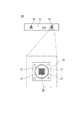
図7は投光器本体3及び電源ケース5の回動範囲について説明する模式図である。
図7に示すように、投光器本体3及び電源ケース5は、取付アーム7が取り付けられる固定部70の面に光軸Kが平行な状態にある平行位置に対して、角度αの範囲内で回動可能になっている。即ち、投光器本体3から出射する光の光軸Kの方向を、角度αの範囲内で可変できるようになっている。この実施形態では、取付アーム7は、水平に延在する固定部70の面に対して取り付けられている。この場合、投光器本体3及び電源ケース5は、光軸Kが水平方向に平行となる平行位置と、光軸Kが水平方向に対して斜め上方に角度αだけ傾斜する傾斜位置との間を回動可能となる。
FIG. 7 is a schematic diagram for explaining the rotation ranges of the projector
As shown in FIG. 7, the
投光器1の設置時には、取付アーム7を固定部70に固定した後、目的の照射方向に合わせて回動軸51を軸心に投光器本体3を回動させ、その状態のまま、当該回動軸51に設けた保持機構で回動不能に保持する。
このとき、回動軸51は、電源ケース5の上端面5Aの側、すなわち、投光器本体3からみた前後中程に設けられることから、投光器1の前後の重量バランスが良好に保たれる。すなわち、この投光器1では、回動軸51より後ろ側の重量は、主として放熱体9の重量、反射鏡26の基端部から中間地点の重量、及び電源ケース5の重量が寄与し、また前側の重量は、主として反射鏡26の中間地点から先端開口33が寄与する。そして、これら前後のそれぞれの重量モーメントが回動軸51を中心にバランスするように構成されている。
When installing the
At this time, the
ここで、投光器本体3の底面13の側に設けた直方体形状の電源ケース5が、例えば鉛直方向に延びた場合、電源ケース5の正面48が受ける風圧荷重が大きくなる。このため、投光器1の重量バランスの設計の際に、風圧荷重の重要度が大きくなり、設計が複雑になる。
これに対し、この投光器1では、電源ケース5が投光器本体3の底面13の中程から、背後に斜めに延びることで、図4の矢印Cで示すように、電源ケース5の正面48で受けた空気が滑らかに背後に流されるため風圧荷重が抑えられることとなる。
Here, when the rectangular parallelepiped
On the other hand, in the
この風圧荷重は、電源ケース5が水平に近くなるほど低減される。しかしながら、この電源ケース5が投光器本体3の中程、すなわち放熱体9の開口端9Bから延びているため、この直上には、図4に示すように、放熱体9の内部に収められたLEDパッケージ29、及び垂直放熱フィン21が位置する。このため、電源ケース5を水平に近付け過ぎると、これらLEDパッケージ29、及び垂直放熱フィン21と電源ケース5が熱的に結合し、相互に影響を及ぼし合ってしまう。
This wind pressure load is reduced as the
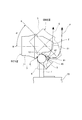
そこで、この投光器1では、投光器本体3に対し、電源ケース5を斜めに延在させることで、図4及び図5に示すように、投光器本体3の放熱体9の底面13に延びた垂直放熱フィン21と、電源ケース5との間に空間Sを設けることとしている。投光器本体3はLEDパッケージ29の位置に応じた箇所に、一点鎖線の円で示す熱源HAを有し、また、電源ケース5は、電源基板49の配置位置に応じた箇所に、一点鎖線の楕円で示す熱源HBを有する。熱源HAの熱は、垂直放熱フィン21に伝導されるが、この空間Sによって放熱体9の底面13の垂直放熱フィン21と、電源ケース5との熱的な結合が分断されることから、両者間の熱的な影響が抑制される。
Therefore, in the
特に、この投光器1が平行位置にある場合、図4及び図5に示すように、電源ケース5が放熱体9の底面13に対し、略45度の角度θ2で延びることで、電源ケース5の正面48が受ける風圧荷重の低減と、電源ケース5と放熱体9の垂直放熱フィン21との間の熱的結合の抑制との良好なバランスが図れることとなる。
また電源ケース5の放熱フィン61は、図4に示すように、その上背面47からの高さTが下端面5Bの側で大きく上端面5Aの側にむかうほど小さくなっている。すなわち、電源ケース5と放熱体9の間の空間Sが狭まるほど、放熱フィン61の高さTが小さくなり、この放熱フィン61からの放熱が抑えられる。これにより、電源ケース5の放熱性能と、この電源ケース5と放熱体9の間の熱的結合の良好なバランスが図られている。
In particular, when the
Further, as shown in FIG. 4, the
電源ケース5が斜め下方に延在することで、電源ケース5の上背面47では、電源基板49の熱気が上昇し、空間Sから外部に逃げる。即ち、水平放熱フィン23の下方に位置する上背面47の部位から放出される電源基板49の熱気は、図4の矢印Dで示すように、上昇して放熱体9の底面13に到達したとしても、底面13から背面12に沿って上方に向かい、空間Sから外部に逃げる。
また、垂直放熱フィン21の下方に位置する上背面47の部位から放出される熱気は、図5及び図7の矢印Eで示すように、放熱体9の背面12に設けられた垂直放熱フィン21の間を通ってスムーズに上昇を続け、投光器1の上方に向かう。また、熱気の一部が、底面13に到達したとしても、放熱体9の底面13、及び背面12に設けられた垂直放熱フィン21の間を通ってスムーズに上昇を続け、投光器1の上方に向かうことから、放熱体9への熱的な影響が抑えられることとなる。また、図7の矢印Fで示すように、投光器本体3及び電源ケース5が傾斜位置にある場合でも、上背面47は、下方に向けられることなく配置されるようになっている。このため、電源基板49の熱気は上背面47から上方に向かい、底面13に到達するものの、大半の熱気は、垂直放熱フィン21の間を通ってスムーズに上昇を続け、投光器1の上方に向かう。
As the
Further, the hot air released from the portion of the
さらに電源ケース5が、図2(B)に示すように、平面視で投光器本体3の背面12から突出しない程度の長さに形成されているため、投光器本体3が電源ケース5を覆う傘の機能を果たし、この電源ケース5に放熱フィン63へのゴミや塵などが入り込むことが防止される。
Further, as shown in FIG. 2B, the
以上説明したように、本実施形態によれば、次のような効果を奏する。
すなわち、本実施形態の投光器1によれば、電源ケース5が放熱体9の垂直放熱フィン21との間に空間Sをあけて設けられているので、電源ケース5と放熱体9との間の熱的結合が抑制され、両者の間での影響が防止される。
As described above, according to the present embodiment, the following effects can be obtained.
That is, according to the
これに加え、本実施形態によれば、電源ケース5が、放熱体9の取付アーム7側に斜めに取り付けられているので、正面側からの風圧荷重を低減しつつ、上記電源ケース5と放熱体9の垂直放熱フィン21との間の空間Sを確保できる。
In addition, according to the present embodiment, since the
また本実施形態によれば、狭角配光を形成する回転放物反射面32を有する反射鏡26がLEDパッケージ29の発光部30を囲うように放熱体9に設けられ、当該反射鏡26の先端を放熱体9から突出させ、当該放熱体9の開口端9Bに電源ケース5を斜めに取付ける構成とした。
これにより、反射鏡26、放熱体9、及び電源ケース5の重量バランスを図りつつ、風圧荷重を抑え、また放熱体9と電源ケース5の間の熱的な影響を抑制することができる。
Further, according to the present embodiment, the reflecting
Thereby, the wind pressure load can be suppressed and the thermal influence between the
また本実施形態によれば、放熱体9には、垂直放熱フィン21と、これと異方向に延びる水平放熱フィン23とを設けたため、投光器1を縦、横のいずれに設置した場合においても放熱性能の低下が防止される。
Further, according to the present embodiment, since the
また本実施形態によれば、放熱体9の開口端9Bに前面カバー11がグローブとして設けられている。これにより、LEDモジュール25や反射鏡26が、外部に露出することがなくなるので、これらの部材に、異物が接触するなどして破損することを防止できる。
Further, according to the present embodiment, the
[第2実施形態]
図8は本発明の第2実施形態に係る投光器100の断面図である。
図8において、投光器100は、反射鏡26に代え光学レンズ65(光学部材)を有する他は、第1実施形態の投光器1と同様に構成されている。
光学レンズ65は、発光部30を覆って設けられ、放熱体9の開口10側に向けられる制御面30Aを有している。光学レンズ65は、発光部30の光を、例えば、平行光にして開口10に向かわせる制御を行う。
この第2実施形態に係る投光器100によれば、上記第1実施形態と同様の効果が得られる上、光学レンズ65を用いることで、長尺となる反射鏡に比べ、LEDパッケージ29の光を制御する光学部材の小型化が期待できる。
[Second Embodiment]
FIG. 8 is a cross-sectional view of a
In FIG. 8, the
The
According to the
なお、上述した実施形態は、あくまでも本発明の一態様を例示したものであって、本発明の趣旨を逸脱しない範囲で任意に変形、及び応用が可能である。
例えば上述した各実施態様では、発光素子の一例としてLEDパッケージ29を例示したが、これに限らず、有機EL等の他の発光素子でも良い。
また、LEDパッケージ29として、LED27を密集配置したCOB型のモジュールを例示したが、これに限らず、LED27を密集させるものに限定されるものではない。
また電源ケース5は、その中に電源基板49を上背面47の側に寄せて収め、この上背面47に放熱フィン61を設ける構成としたが、これに限らない。すなわち、前掲図6に破線で示すように、電源ケース5の正面48に放熱フィン61を設け、この正面48の側に寄せて電源基板49を収めても良い。
The above-described embodiment is merely an example of one aspect of the present invention, and can be arbitrarily modified and applied without departing from the spirit of the present invention.
For example, in each of the above-described embodiments, the
Moreover, although the COB type module in which the
Further, the
1 投光器(照明器具)
3 投光器本体
5 電源ケース
7 取付アーム
9 放熱体
9B 開口端
11 前面カバー(グローブ)
26 反射鏡
27 LED(発光素子)
21 垂直放熱フィン(放熱体の放熱フィン)
23 水平放熱フィン(放熱体の放熱フィン)
61,63 電源ケースの放熱フィン
49 電源基板
70 固定部
1 Floodlight (lighting fixture)
3
26
21 Vertical heat radiating fin (heat radiating fin)
23 Horizontal heat radiating fin (heat radiating fin)
61, 63 Radiation fins of the
Claims (5)
前記発光素子の電源回路を収納し、外表面に放熱フィンを備えた電源ケースと、
前記電源ケースに設けられた取付アームと、を備え、
前記電源ケースは、前記放熱体からみて前記取付アームが延びる側に前記放熱体の放熱フィンとの間に空間をあけて設けられ、前記放熱体から連続し、背面の側に斜めに延びて設けられている
ことを特徴とする照明器具。 A radiator that houses a light emitting element, has an opening for emitting light of the light emitting element on the front surface, and has a heat radiating fin on the outer surface;
A power supply case that houses the power supply circuit of the light emitting element and has a heat radiation fin on the outer surface;
A mounting arm provided in the power supply case,
The power supply case is provided with a space between the heat dissipating fin and the heat dissipating fin on the side where the mounting arm extends when viewed from the heat dissipating body, and is provided continuously from the heat dissipating body and obliquely extending to the back side. It is characterized by being lit.
前記電源ケースは、前記底面に対して略45度の角度で延びていることを特徴とする請求項1または2に記載の照明器具。 The lighting apparatus according to claim 1, wherein the power supply case extends at an angle of about 45 degrees with respect to the bottom surface.
Priority Applications (2)
| Application Number | Priority Date | Filing Date | Title |
|---|---|---|---|
| JP2013040922A JP5758424B2 (en) | 2013-03-01 | 2013-03-01 | lighting equipment |
| PCT/JP2013/083762 WO2014132530A1 (en) | 2013-03-01 | 2013-12-17 | Illuminating instrument |
Applications Claiming Priority (1)
| Application Number | Priority Date | Filing Date | Title |
|---|---|---|---|
| JP2013040922A JP5758424B2 (en) | 2013-03-01 | 2013-03-01 | lighting equipment |
Publications (3)
| Publication Number | Publication Date |
|---|---|
| JP2014170640A JP2014170640A (en) | 2014-09-18 |
| JP2014170640A5 JP2014170640A5 (en) | 2015-01-22 |
| JP5758424B2 true JP5758424B2 (en) | 2015-08-05 |
Family
ID=51427816
Family Applications (1)
| Application Number | Title | Priority Date | Filing Date |
|---|---|---|---|
| JP2013040922A Active JP5758424B2 (en) | 2013-03-01 | 2013-03-01 | lighting equipment |
Country Status (2)
| Country | Link |
|---|---|
| JP (1) | JP5758424B2 (en) |
| WO (1) | WO2014132530A1 (en) |
Families Citing this family (5)
| Publication number | Priority date | Publication date | Assignee | Title |
|---|---|---|---|---|
| WO2016080004A1 (en) * | 2014-11-19 | 2016-05-26 | 三菱化学株式会社 | Spot lighting device |
| JP6544513B2 (en) * | 2014-11-19 | 2019-07-17 | 三菱ケミカル株式会社 | Spot lighting device |
| KR101756187B1 (en) * | 2015-03-10 | 2017-07-26 | 대우조선해양 주식회사 | Compact flood light using COB LED array |
| DE102015205003B4 (en) | 2015-03-19 | 2016-12-08 | Glp German Light Products Gmbh | lighting device |
| JP7450252B2 (en) | 2020-04-22 | 2024-03-15 | オーデリック株式会社 | variable lighting device |
Family Cites Families (7)
| Publication number | Priority date | Publication date | Assignee | Title |
|---|---|---|---|---|
| JP2002313119A (en) * | 2001-04-13 | 2002-10-25 | Hitachi Ltd | Light source for projection device and projection type image display device |
| JP4511082B2 (en) * | 2001-07-11 | 2010-07-28 | 株式会社アイ・ライティング・システム | lighting equipment |
| US7152997B1 (en) * | 2005-10-04 | 2006-12-26 | Alert Safety Lite Products Co., Inc. | LED utility light with stand |
| JP5553977B2 (en) * | 2008-08-22 | 2014-07-23 | 株式会社アイ・ライティング・システム | LED lighting fixtures |
| JP5263516B2 (en) * | 2008-10-22 | 2013-08-14 | 東芝ライテック株式会社 | Light source unit and lighting apparatus |
| JP5331512B2 (en) * | 2009-02-26 | 2013-10-30 | 株式会社アイ・ライティング・システム | LED lighting equipment |
| JP5612380B2 (en) * | 2010-06-24 | 2014-10-22 | 株式会社アイ・ライティング・システム | LED lighting fixtures |
-
2013
- 2013-03-01 JP JP2013040922A patent/JP5758424B2/en active Active
- 2013-12-17 WO PCT/JP2013/083762 patent/WO2014132530A1/en active Application Filing
Also Published As
| Publication number | Publication date |
|---|---|
| WO2014132530A1 (en) | 2014-09-04 |
| JP2014170640A (en) | 2014-09-18 |
Similar Documents
| Publication | Publication Date | Title |
|---|---|---|
| US9482395B2 (en) | LED luminaire | |
| JP5182634B2 (en) | lighting equipment | |
| JP4497073B2 (en) | Vehicle lighting | |
| JP5758424B2 (en) | lighting equipment | |
| JP6539665B2 (en) | Sports lighting equipment | |
| JP2011210468A (en) | Road illumination device | |
| US20110205741A1 (en) | Lighting equipment | |
| JP2007172932A (en) | Vehicular headlight | |
| JP6341804B2 (en) | Heat dissipation structure | |
| JP2013134912A (en) | Lighting device for high-speed photographing | |
| JP2016162597A (en) | Lighting device | |
| JP3173200U (en) | LED lamp | |
| JP2016201210A (en) | lamp | |
| JP6433016B2 (en) | Large light LED floodlight | |
| JP6251081B2 (en) | Reflection unit and LED module | |
| EP2902702A1 (en) | Lighting device | |
| JP5304572B2 (en) | Light emitting module and lighting apparatus equipped with the same | |
| JP2011159549A (en) | Light source unit and lighting system | |
| JP5590658B2 (en) | Lighting device | |
| JP2010176926A (en) | Vehicular lighting fixture | |
| JP2015212997A (en) | Lighting device | |
| JP6624546B2 (en) | lighting equipment | |
| JP5971542B2 (en) | LED lighting fixtures | |
| JP5955594B2 (en) | Lighting device | |
| JP6694604B2 (en) | Lighting equipment |
Legal Events
| Date | Code | Title | Description |
|---|---|---|---|
| A521 | Written amendment |
Free format text: JAPANESE INTERMEDIATE CODE: A523 Effective date: 20141201 |
|
| A621 | Written request for application examination |
Free format text: JAPANESE INTERMEDIATE CODE: A621 Effective date: 20141201 |
|
| A871 | Explanation of circumstances concerning accelerated examination |
Free format text: JAPANESE INTERMEDIATE CODE: A871 Effective date: 20141201 |
|
| A975 | Report on accelerated examination |
Free format text: JAPANESE INTERMEDIATE CODE: A971005 Effective date: 20150129 |
|
| A131 | Notification of reasons for refusal |
Free format text: JAPANESE INTERMEDIATE CODE: A131 Effective date: 20150203 |
|
| A521 | Written amendment |
Free format text: JAPANESE INTERMEDIATE CODE: A523 Effective date: 20150403 |
|
| TRDD | Decision of grant or rejection written | ||
| A01 | Written decision to grant a patent or to grant a registration (utility model) |
Free format text: JAPANESE INTERMEDIATE CODE: A01 Effective date: 20150519 |
|
| A61 | First payment of annual fees (during grant procedure) |
Free format text: JAPANESE INTERMEDIATE CODE: A61 Effective date: 20150603 |
|
| R150 | Certificate of patent or registration of utility model |
Ref document number: 5758424 Country of ref document: JP Free format text: JAPANESE INTERMEDIATE CODE: R150 |