JP5755259B2 - Long nozzle for continuous casting - Google Patents
Long nozzle for continuous casting Download PDFInfo
- Publication number
- JP5755259B2 JP5755259B2 JP2013001612A JP2013001612A JP5755259B2 JP 5755259 B2 JP5755259 B2 JP 5755259B2 JP 2013001612 A JP2013001612 A JP 2013001612A JP 2013001612 A JP2013001612 A JP 2013001612A JP 5755259 B2 JP5755259 B2 JP 5755259B2
- Authority
- JP
- Japan
- Prior art keywords
- gas
- nozzle
- refractory
- head
- nozzle body
- Prior art date
- Legal status (The legal status is an assumption and is not a legal conclusion. Google has not performed a legal analysis and makes no representation as to the accuracy of the status listed.)
- Expired - Fee Related
Links
Images
Landscapes
- Continuous Casting (AREA)
Description
本発明は、溶鋼を取鍋からタンディッシュに注入する際に、取鍋底部に配設される流量制御用スライデングノズルのコレクターノズルから流出する溶鋼を、大気による酸化防止をしながらタンディッシュに注入するために使用される連続鋳造用ロングノズルに関する。 In the present invention, when pouring molten steel from a ladle into a tundish, the molten steel flowing out from the collector nozzle of the flow control sliding nozzle disposed at the bottom of the ladle is tundished while preventing oxidation by the atmosphere. The present invention relates to a continuous casting long nozzle used for pouring.
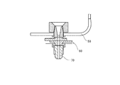
溶融金属、特に鋼の連続鋳造においては、取鍋からタンディッシュへの溶鋼の注入に際して溶鋼流の流量制御を行うため、取鍋の底部に取り付けられるスライディングゲートが使用される。図4に取鍋50の底部に取り付けられたスライディングゲート60を示す。
In continuous casting of molten metal, particularly steel, a sliding gate attached to the bottom of the ladle is used to control the flow rate of the molten steel flow when the molten steel is poured from the ladle into the tundish. FIG. 4 shows a
このスライディングゲート60の下側にはいわゆるコレクターノズル70が配設されており、このコレクターノズル70からタンディッシュ(図示しない)への溶鋼注入に際して、ロングノズルは、大気による溶鋼の酸化を防止し、溶鋼のスプラッシュ飛散を防止するなどの目的で用いられる。
A so-called
そして、取鍋50からタンディッシュへの溶鋼注入時には、溶鋼がロングノズル内孔を急速に流れ落ちるため、この溶鋼の動圧により、内孔内の圧力が外部の大気圧に対して負圧となる現象が生じる。この圧力差によりロングノズルとコレクターノズルとの嵌合部からロングノズル内孔へ大気が吸引される。吸引された空気によりロングノズル内孔内を流下している溶鋼が酸化され、その結果として鋳造された鋼の清浄度等の品質並びに歩留の著しい低下を招くと共に、ロングノズル内孔面の溶損が大きくなるという問題があった。
When molten steel is poured from the
上記問題に対して、嵌合部からの大気吸引による溶鋼の酸化を防止する方法として、この嵌合部周辺にアルゴンガスや窒素ガスなどの不活性ガスを吹き込む方法が行われている。 In order to prevent the molten steel from being oxidized due to atmospheric suction from the fitting portion, a method of blowing an inert gas such as argon gas or nitrogen gas around the fitting portion has been performed.
図5は、本願発明者らが実開平1−100656号公報において開示した従来技術の一例を示した図である。この図に示すように、従来は、頭部がメタルケース41に被覆されたロングノズル20の上端開口からコレクターノズル70が挿入嵌合され装着された状態で、不活性ガス吹込口42から、ガスプール40およびロングノズル20を構成する耐火物の上端に放射状に設けられた溝43を介して不活性ガスが吹き込まれ、嵌合部30の上部の大気が不活性ガスに置換されることで、嵌合部30からの大気の吸い込みを制御しガスシールを形成していた。
FIG. 5 is a diagram showing an example of the prior art disclosed in Japanese Utility Model Laid-Open No. 1-100656 by the present inventors. As shown in this figure, conventionally, in a state where the
しかし、ロングノズル20を構成する耐火物の上端に放射状に設けられた溝43からのみでは十分なガスシールが得られないという問題があった。
However, there is a problem that a sufficient gas seal cannot be obtained only from the
そこで、本発明の課題は、ロングノズルとコレクターノズルとの嵌合部の上部に十分なガスシールを形成でき、嵌合部からの大気吸引による溶鋼の酸化を防止すると共にロングノズル内孔面の溶損を軽減できる連続鋳造用ロングノズルを提供することにある。 Therefore, the problem of the present invention is that a sufficient gas seal can be formed on the upper portion of the fitting portion between the long nozzle and the collector nozzle, preventing oxidation of the molten steel due to atmospheric suction from the fitting portion, and the inner surface of the inner surface of the long nozzle. An object of the present invention is to provide a long nozzle for continuous casting that can reduce melting damage.
上記課題を解決するものは、取鍋の底部に取り付けられたスライディングゲートのコレクターノズルに嵌合される連続鋳造用ロングノズルであって、前記コレクターノズルからの溶湯を下方に流通させるノズル内孔を有した耐火物製ノズル本体と、該耐火物製ノズル本体の頭部を被覆したメタルケースと、該メタルケースの側壁に設けられたガス導入口から前記コレクターノズルと前記耐火物製ノズル本体との嵌合部の上部環状空間に不活性ガスを吹き出す第1ガス流路および第2ガス流路とを有し、前記第1ガス流路は、前記ガス導入口に連通し前記メタルケースと前記耐火物製ノズル本体の頭部側壁との間に設けられたガスプールと、該ガスプールに連通すると共に前記メタルケースと前記耐火物製ノズル本体の頭部上面との間に放射状に配された複数の溝とから構成され、前記第2ガス流路は、前記耐火物製ノズル本体の頭部内に放射状に複数設けられ前記ガスプールと前記嵌合部の上部環状空間とを連通させる貫通孔から構成され、前記溝または/および前記貫通孔は、平面視でガス導入口が設けられた側とガス導入口が設けられていない側とに二分して視た場合、前記ガス導入口が設けられた側より、前記ガス導入口が設けられていない側の方が多く形成され、さらに、前記溝および前記貫通孔は、平面視で前記ガス導入口が設けられた位置に配置されていないことを特徴とする連続鋳造用ロングノズルである。 What solves the above-described problem is a long nozzle for continuous casting fitted to a collector nozzle of a sliding gate attached to the bottom of a ladle, and has a nozzle inner hole through which molten metal from the collector nozzle flows downward. A refractory nozzle body, a metal case covering a head of the refractory nozzle body, and a gas inlet provided on a side wall of the metal case, the collector nozzle and the refractory nozzle body. A first gas flow path and a second gas flow path for blowing an inert gas into the upper annular space of the fitting portion , the first gas flow path communicating with the gas inlet and the metal case and the fireproof radially between the gas pool is provided between the head side wall made of the nozzle body object, a head upper surface of the refractory steel nozzle body and the metal casing communicates with the said gas pool Is composed of a provided plurality of grooves are, the second gas flow path communicates the upper annular space radially arranged plurality in the head of the refractory steel nozzle body and the gas pool the fitting portion The groove or / and the through-hole is divided into a gas introduction port side and a side not provided with the gas introduction port in plan view, the gas introduction The side where the gas introduction port is not provided is formed more than the side where the port is provided, and the groove and the through hole are arranged at the position where the gas introduction port is provided in plan view. It is a long nozzle for continuous casting characterized by not having.
前記溝および前記貫通孔の総断面積は、前記ガス導入口の断面積に比して小さいことが好ましい。 The total cross-sectional area of the groove and the through hole is preferably smaller than the cross-sectional area of the gas inlet.
請求項1に記載した連続鋳造用ロングノズルによれば、ロングノズルとコレクターノズルとの嵌合部の上部に十分なガスシールを形成することができ、嵌合部からの大気吸引による溶鋼の酸化を防止すると共にロングノズル内孔面の溶損を軽減できる。また、耐火物製ノズル本体の頭部の全周からより均一なガスシールを確保できる。さらに、ガス導入口側からの不活性ガスの偏流を防止することができる。
請求項2に記載した連続鋳造用ロングノズルによれば、上記請求項1の効果に加え、背圧を確保して溝および貫通孔の先端ガス吹き部から不活性ガスを確実に流入させることができる。
According to the long nozzle for continuous casting described in claim 1, a sufficient gas seal can be formed on the upper portion of the fitting portion between the long nozzle and the collector nozzle, and oxidation of molten steel by atmospheric suction from the fitting portion. Can be prevented, and melting of the inner surface of the long nozzle can be reduced. Further, a more uniform gas seal can be secured from the entire circumference of the head of the refractory nozzle body. Furthermore, the drift of the inert gas from the gas inlet side can be prevented.
According to the long nozzle for continuous casting described in
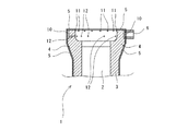
本発明では、ガス導入口6に連通しメタルケース5と耐火物製ノズル本体3の頭部4側壁との間に設けられたガスプール10と、ガスプール10に連通すると共にメタルケース5と耐火物製ノズル本体3の頭部4上面との間に設けられた溝11とから構成された第1ガス流路に加え、耐火物製ノズル本体3の頭部4内に設けられガスプール10と嵌合部7の上部近傍付近とを連通させる貫通孔12とから構成された第2ガス流路を設けたことで、ガスシールが最も必要な部位である、ロングノズルとコレクターノズルとの嵌合部の上部に不活性ガスを直にかつ集中的に流入させるため、十分なガスシールを形成することができ、嵌合部からの大気吸引による溶鋼の酸化を防止すると共にロングノズル内孔面の溶損を軽減できる連続鋳造用ロングノズル1を実現した。
In the present invention, a
本発明の連続鋳造用ロングノズルを図1ないし図3に示した一実施例を用いて説明する。
この実施例の連続鋳造用ロングノズル1は、図1に示すように、取鍋の底部に取り付けられたスライディングゲートのコレクターノズル70に嵌合される連続鋳造用ロングノズルであって、コレクターノズル70からの溶湯を下方に流通させるノズル内孔2を有した耐火物製ノズル本体3と、耐火物製ノズル本体3の頭部4を被覆したメタルケース5と、メタルケース5の側壁に設けられたガス導入口6からコレクターノズル70と耐火物製ノズル本体3との嵌合部7近傍に不活性ガスを吹き出す第1ガス流路および第2ガス流路とを有し、第1ガス流路は、ガス導入口6に連通しメタルケース5と耐火物製ノズル本体3の頭部4側壁との間に設けられたガスプール10と、ガスプール10に連通すると共にメタルケース5と耐火物製ノズル本体3の頭部4上面との間に設けられた溝11とから構成され、第2ガス流路は、耐火物製ノズル本体3の頭部4内に設けられガスプール10と嵌合部7の上部近傍付近とを連通させる貫通孔12とから構成されている。以下、各構成について順次詳述する。
A long nozzle for continuous casting according to the present invention will be described with reference to an embodiment shown in FIGS.
As shown in FIG. 1, the continuous casting long nozzle 1 of this embodiment is a continuous casting long nozzle fitted to a sliding
耐火物製ノズル本体3は、黒鉛等や有機樹脂等の炭素含有原料と様々な酸化物を組み合わせて形成した耐火物により構成されており、略円筒体で、その上部には上方に向かって拡径した頭部4が設けられている。耐火物製ノズル本体3の中心部には、溶鋼が流れるノズル内孔2がノズル本体3の上端開口から下端まで貫通して形成されている。
The
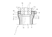
連続鋳造用ロングノズル1は、図3に示すように、取鍋の底部に取り付けられたスライディングゲートのコレクターノズル70に嵌合される。具体的には、連続鋳造用ロングノズル1は頭部4内のソケット状の嵌合部7でコレクターノズル70と接合される。
As shown in FIG. 3, the continuous casting long nozzle 1 is fitted to a sliding
耐火物製ノズル本体3の頭部4付近は、メタルケース(鉄皮)5にて被覆されており、メタルケース5の側壁に設けられたガス導入口6からコレクターノズル70と耐火物製ノズル本体3との嵌合部7近傍に不活性ガスを吹き出す第1ガス流路および第2ガス流路が耐火物製ノズル本体3の頭部4付近に形成されている。
The vicinity of the
第1ガス流路は、図1に示すように、ガス導入口6に連通しメタルケース5と耐火物製ノズル本体3の頭部4側壁との間に設けられたガスプール10と、ガスプール10に連通すると共にメタルケース5と耐火物製ノズル本体3の頭部4上面との間に設けられた溝11とから構成されている。
As shown in FIG. 1, the first gas flow path includes a
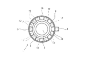
図2は耐火物製ノズル本体3の頭部4の上方に存在するメタルケース(鉄皮)5を省略した平面概略図であるが、ガスプール10は、耐火物製ノズル本体3の頭部4の外方に環状に設けられており、ガス導入口6から導入される不活性ガスがガスプール10を介して耐火物製ノズル本体3の頭部4の全周に行き渡るように構成されている。
FIG. 2 is a schematic plan view in which the metal case (iron skin) 5 existing above the
溝11は、耐火物製ノズル本体3の頭部4の上面に放射状に配された複数の溝からなる。これにより、耐火物製ノズル本体3の頭部4の全周から不活性ガスを流入させることができる。なお、この実施例の溝11は、頭部4の上面に等角度離間して配されているが、これに限定されるものではなく、溝は平面視でガス導入口が設けられた側とガス導入口が設けられていない側とに二分して視た場合、ガス導入口が設けられた側より、ガス導入口が設けられていない側の方が多く形成されていることが好ましい。これにより、耐火物製ノズル本体の頭部の全周からより均一なガスシールが確保できる。
The
また、溝11は、平面視でガス導入口6が設けられた位置に配置されていない。これにより、ガス導入口6側からの不活性ガスの偏流を防止することができるように構成されている。
Moreover, the groove |
そして、不活性ガスをガス導入口6から導入すると、ガスプール10および溝11を経由して耐火物製ノズル本体3の頭部4の上方から嵌合部7に流入するように構成されている。なお、不活性ガスとしては窒素ガス、Arガス等が望ましく、鋼の窒素量が問題となる場合にはArガスが望ましい。
When the inert gas is introduced from the
さらに、本発明の連続鋳造用ロングノズルは、上記第1ガス流路に加え、耐火物製ノズル本体3の頭部4内に設けられガスプール10と嵌合部7の上部近傍付近とを連通させる貫通孔12とから構成された第2ガス流路を設けたことで、ガスシールが最も必要な部位である、ロングノズルとコレクターノズルとの嵌合部の上部に直にかつ集中的に不活性ガスが流入されるため、十分なガスシールを形成することができ、嵌合部からの大気吸引による溶鋼の酸化を防止すると共にロングノズル内孔面の溶損を軽減できるように構成されている。
Further, the long nozzle for continuous casting according to the present invention is provided in the
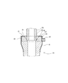
貫通孔12は、図3に示すように、基端側開口がガスプール10と連通し、先端側開口が嵌合部7の上部近傍付近に位置するように略水平方向に沿って設けられている。なお、この実施例では、貫通孔12は略水平方向同一レベルに設けられているが、若干異なるレベルに(上下に千鳥状に)点在して設けられたものも本発明の範疇に包含される。
As shown in FIG. 3, the through-
貫通孔12は、図2に示すように、複数の貫通孔から構成されており、耐火物製ノズル本体3の頭部4内において放射状に配されている。これにより、耐火物製ノズル本体3の頭部4の全周から不活性ガスを嵌合部7の上部近傍付近に流入させることができるように構成されている。
As shown in FIG. 2, the through
貫通孔12は、平面視でガス導入口6が設けられた側とガス導入口6が設けられていない側とに二分して視た場合、ガス導入口6が設けられた側より、ガス導入口6が設けられていない側の方が多く形成されている。この実施例では、図2に示すように、ガス導入口6が設けられた側には4本の貫通孔12が設けられており、ガス導入口6が設けられていない側には7本の貫通孔12が設けられている。これにより、全周からより均一なガスシールが確保できるように構成されている。
When the through-
また、貫通孔12は、平面視でガス導入口6が設けられた位置に配置されていない。これにより、ガス導入口6側からの不活性ガスの偏流を防止することができるように構成されている。
Moreover, the through-
さらに、溝11および貫通孔12の総断面積は、ガス導入口6の断面積に比して小さくなるように形成されている。これにより、背圧を確保して溝11および貫通孔12の先端ガス吹き部から不活性ガスを確実に流入させることができる。
Further, the total cross-sectional area of the
図5に示した従来のロングノズル20(耐火物の上端に放射状に設けられた溝43のみを介して不活性ガスが吹き込まれるもの)と本発明のロングノズル1(溝11に加え貫通孔12を介して不活性ガスが吹き込まれるもの)との廃却要因を調査し対比したところ、従来のロングノズル20は内孔面の溶損が要因で廃却されたものが全体の12%であるのに対して、本発明のロングノズル1は2%と内孔面の溶損が要因で廃却されるものが減少した。
The conventional
以上のように、本発明の連続鋳造用ロングノズルでは、第1ガス流路に加え、耐火物製ノズル本体3の頭部4内に設けられガスプール10と嵌合部7の上部近傍付近とを連通させる貫通孔12とから構成された第2ガス流路を設けたことで、ガスシールが最も必要な部位である、ロングノズルとコレクターノズルとの嵌合部の上部に不活性ガスが直にかつ集中的に流入するため、十分なガスシールを形成することができ、嵌合部からの大気吸引による溶鋼の酸化を防止すると共にロングノズル内孔面の溶損を軽減できる。
As described above, in the long nozzle for continuous casting according to the present invention, in addition to the first gas flow path, the vicinity of the upper portion of the
1 連続鋳造用ロングノズル
2 ノズル内孔
3 耐火物製ノズル本体
4 耐火物製ノズル本体の頭部
5 メタルケース
6 ガス導入口
7 嵌合部
10 ガスプール
11 溝
12 貫通孔
70 コレクターノズル
DESCRIPTION OF SYMBOLS 1 Long nozzle for
Claims (2)
前記コレクターノズルからの溶湯を下方に流通させるノズル内孔を有した耐火物製ノズル本体と、
該耐火物製ノズル本体の頭部を被覆したメタルケースと、
該メタルケースの側壁に設けられたガス導入口から前記コレクターノズルと前記耐火物製ノズル本体との嵌合部の上部環状空間に不活性ガスを吹き出す第1ガス流路および第2ガス流路とを有し、
前記第1ガス流路は、前記ガス導入口に連通し前記メタルケースと前記耐火物製ノズル本体の頭部側壁との間に設けられたガスプールと、該ガスプールに連通すると共に前記メタルケースと前記耐火物製ノズル本体の頭部上面との間に放射状に配された複数の溝とから構成され、
前記第2ガス流路は、前記耐火物製ノズル本体の頭部内に放射状に複数設けられ前記ガスプールと前記嵌合部の上部環状空間とを連通させる貫通孔から構成され、
前記溝または/および前記貫通孔は、平面視でガス導入口が設けられた側とガス導入口が設けられていない側とに二分して視た場合、前記ガス導入口が設けられた側より、前記ガス導入口が設けられていない側の方が多く形成され、
さらに、前記溝および前記貫通孔は、平面視で前記ガス導入口が設けられた位置に配置されていないことを特徴とする連続鋳造用ロングノズル。 A long nozzle for continuous casting fitted to a collector nozzle of a sliding gate attached to the bottom of the ladle,
A refractory nozzle body having a nozzle bore through which the molten metal from the collector nozzle flows downward;
A metal case covering the head of the refractory nozzle body;
A first gas flow path and a second gas flow path for blowing an inert gas from a gas inlet provided in a side wall of the metal case to an upper annular space of a fitting portion between the collector nozzle and the refractory nozzle body; Have
The first gas flow path communicates with the gas inlet, a gas pool provided between the metal case and a head side wall of the refractory nozzle body, and communicates with the gas pool and the metal case. And a plurality of grooves arranged radially between the top surface of the head of the refractory nozzle body,
The second gas flow path includes a plurality of through holes that are provided radially in the head of the refractory nozzle body and communicate the gas pool with the upper annular space of the fitting portion.
When the groove or / and the through hole are viewed in two parts, a side where the gas introduction port is provided and a side where the gas introduction port is not provided in a plan view, from the side where the gas introduction port is provided. , More on the side where the gas inlet is not provided,
Further, the continuous casting long nozzle is characterized in that the groove and the through hole are not arranged at a position where the gas introduction port is provided in a plan view .
Priority Applications (1)
| Application Number | Priority Date | Filing Date | Title |
|---|---|---|---|
| JP2013001612A JP5755259B2 (en) | 2013-01-09 | 2013-01-09 | Long nozzle for continuous casting |
Applications Claiming Priority (1)
| Application Number | Priority Date | Filing Date | Title |
|---|---|---|---|
| JP2013001612A JP5755259B2 (en) | 2013-01-09 | 2013-01-09 | Long nozzle for continuous casting |
Publications (2)
| Publication Number | Publication Date |
|---|---|
| JP2014133241A JP2014133241A (en) | 2014-07-24 |
| JP5755259B2 true JP5755259B2 (en) | 2015-07-29 |
Family
ID=51411956
Family Applications (1)
| Application Number | Title | Priority Date | Filing Date |
|---|---|---|---|
| JP2013001612A Expired - Fee Related JP5755259B2 (en) | 2013-01-09 | 2013-01-09 | Long nozzle for continuous casting |
Country Status (1)
| Country | Link |
|---|---|
| JP (1) | JP5755259B2 (en) |
Families Citing this family (4)
| Publication number | Priority date | Publication date | Assignee | Title |
|---|---|---|---|---|
| CN110809499B (en) | 2017-06-20 | 2022-01-11 | 黑崎播磨株式会社 | Nozzle for casting |
| JP7184327B2 (en) * | 2018-08-28 | 2022-12-06 | 明智セラミックス株式会社 | Long nozzle for continuous casting |
| CN111299565A (en) * | 2019-12-27 | 2020-06-19 | 泰州市旺鑫耐火材料有限公司 | Anti-oxidation high-brushing-resistance long nozzle |
| CN113953503A (en) * | 2021-10-23 | 2022-01-21 | 宜兴市耐火材料有限公司 | Long nozzle for molten steel continuous casting production |
Family Cites Families (11)
| Publication number | Priority date | Publication date | Assignee | Title |
|---|---|---|---|---|
| JPS4922339A (en) * | 1972-06-22 | 1974-02-27 | ||
| JPS52100014U (en) * | 1976-01-24 | 1977-07-28 | ||
| ZA821071B (en) * | 1981-03-03 | 1983-01-26 | Flogates Ltd | Improvements in the pouring of molten metals |
| JPS5934857U (en) * | 1982-08-30 | 1984-03-03 | 株式会社クボタ | Inert gas seal jig for casting molten metal flow |
| JPS62130753A (en) * | 1985-12-02 | 1987-06-13 | Akechi Ceramics Kk | Nozzle for continuous casting |
| JPH0665432B2 (en) * | 1986-01-21 | 1994-08-24 | 住友金属工業株式会社 | Molten metal discharge device |
| JPS6390563U (en) * | 1986-12-02 | 1988-06-11 | ||
| JPH0315244Y2 (en) * | 1987-12-21 | 1991-04-03 | ||
| JPH02104454A (en) * | 1988-10-11 | 1990-04-17 | Akechi Ceramics Kk | Nozzle for continuous casting |
| JPH04270037A (en) * | 1991-01-07 | 1992-09-25 | Akechi Ceramics Kk | Continuous casting nozzle |
| JPH0576656U (en) * | 1992-03-24 | 1993-10-19 | 東京窯業株式会社 | Tundish upper nozzle |
-
2013
- 2013-01-09 JP JP2013001612A patent/JP5755259B2/en not_active Expired - Fee Related
Also Published As
| Publication number | Publication date |
|---|---|
| JP2014133241A (en) | 2014-07-24 |
Similar Documents
| Publication | Publication Date | Title |
|---|---|---|
| JP5755259B2 (en) | Long nozzle for continuous casting | |
| US4756452A (en) | Molten metal pouring nozzle | |
| JPS6133745A (en) | Collector nozzle for device for controlling outflow of cast steel from ladle or tundish | |
| CN204842961U (en) | Get rid of immersion nozzle of inclusion | |
| CN203459651U (en) | Submersed nozzle with flow control vanes | |
| US5885473A (en) | Long nozzle for continuous casting | |
| CN105108132A (en) | Nitrogen-increase-preventing long nozzle for continuous casting ladle | |
| KR102132983B1 (en) | Nozzle structure | |
| KR100986053B1 (en) | Well Block for Molten Steel Casting | |
| JP5643583B2 (en) | Gas blown refractory | |
| JP5835131B2 (en) | Immersion nozzle | |
| CN102239019B (en) | Immersion nozzle | |
| JP2019524450A (en) | Tundish funnel | |
| CN201931060U (en) | Long nozzle for continuous casting | |
| CA2744385C (en) | Tundish impact pad | |
| JPH0330461B2 (en) | ||
| CA2843171C (en) | Ceramic refractory stopper | |
| CN107983943B (en) | A system and method for improving the cleanliness of molten steel in a tundish in an unsteady state | |
| CA2747887A1 (en) | Submerged entry nozzle | |
| KR101496016B1 (en) | Tundish | |
| CN204381356U (en) | The stopper in steel furnace life is watered in a kind of raising | |
| CN212042646U (en) | Tundish quick-change nozzle with high safety coefficient and long service life | |
| JP4210063B2 (en) | Tundish nozzle | |
| JP2012101250A (en) | Gas blowing nozzle | |
| JPS6243649Y2 (en) |
Legal Events
| Date | Code | Title | Description |
|---|---|---|---|
| A977 | Report on retrieval |
Free format text: JAPANESE INTERMEDIATE CODE: A971007 Effective date: 20150121 |
|
| A131 | Notification of reasons for refusal |
Free format text: JAPANESE INTERMEDIATE CODE: A131 Effective date: 20150225 |
|
| A521 | Request for written amendment filed |
Free format text: JAPANESE INTERMEDIATE CODE: A523 Effective date: 20150424 |
|
| TRDD | Decision of grant or rejection written | ||
| A01 | Written decision to grant a patent or to grant a registration (utility model) |
Free format text: JAPANESE INTERMEDIATE CODE: A01 Effective date: 20150521 |
|
| A61 | First payment of annual fees (during grant procedure) |
Free format text: JAPANESE INTERMEDIATE CODE: A61 Effective date: 20150526 |
|
| R150 | Certificate of patent or registration of utility model |
Ref document number: 5755259 Country of ref document: JP Free format text: JAPANESE INTERMEDIATE CODE: R150 |
|
| R250 | Receipt of annual fees |
Free format text: JAPANESE INTERMEDIATE CODE: R250 |
|
| R250 | Receipt of annual fees |
Free format text: JAPANESE INTERMEDIATE CODE: R250 |
|
| R250 | Receipt of annual fees |
Free format text: JAPANESE INTERMEDIATE CODE: R250 |
|
| LAPS | Cancellation because of no payment of annual fees |