JP5750445B2 - Furnace with easy to remove combustion tube - Google Patents
Furnace with easy to remove combustion tube Download PDFInfo
- Publication number
- JP5750445B2 JP5750445B2 JP2012531060A JP2012531060A JP5750445B2 JP 5750445 B2 JP5750445 B2 JP 5750445B2 JP 2012531060 A JP2012531060 A JP 2012531060A JP 2012531060 A JP2012531060 A JP 2012531060A JP 5750445 B2 JP5750445 B2 JP 5750445B2
- Authority
- JP
- Japan
- Prior art keywords
- furnace
- cam
- combustion tube
- pin
- combustion
- Prior art date
- Legal status (The legal status is an assumption and is not a legal conclusion. Google has not performed a legal analysis and makes no representation as to the accuracy of the status listed.)
- Active
Links
- 238000002485 combustion reaction Methods 0.000 title claims description 103
- 238000007789 sealing Methods 0.000 claims description 20
- 230000007246 mechanism Effects 0.000 claims description 15
- 230000013011 mating Effects 0.000 claims 1
- 238000004140 cleaning Methods 0.000 description 6
- 230000006698 induction Effects 0.000 description 6
- QVGXLLKOCUKJST-UHFFFAOYSA-N atomic oxygen Chemical compound [O] QVGXLLKOCUKJST-UHFFFAOYSA-N 0.000 description 5
- 229910052760 oxygen Inorganic materials 0.000 description 5
- 239000001301 oxygen Substances 0.000 description 5
- 239000010453 quartz Substances 0.000 description 4
- 239000000523 sample Substances 0.000 description 4
- VYPSYNLAJGMNEJ-UHFFFAOYSA-N silicon dioxide Inorganic materials O=[Si]=O VYPSYNLAJGMNEJ-UHFFFAOYSA-N 0.000 description 4
- 230000008878 coupling Effects 0.000 description 3
- 238000010168 coupling process Methods 0.000 description 3
- 238000005859 coupling reaction Methods 0.000 description 3
- 239000012530 fluid Substances 0.000 description 3
- 230000008901 benefit Effects 0.000 description 2
- 239000006227 byproduct Substances 0.000 description 2
- 239000007789 gas Substances 0.000 description 2
- 238000010438 heat treatment Methods 0.000 description 2
- NJPPVKZQTLUDBO-UHFFFAOYSA-N novaluron Chemical compound C1=C(Cl)C(OC(F)(F)C(OC(F)(F)F)F)=CC=C1NC(=O)NC(=O)C1=C(F)C=CC=C1F NJPPVKZQTLUDBO-UHFFFAOYSA-N 0.000 description 2
- 239000000538 analytical sample Substances 0.000 description 1
- 239000000919 ceramic Substances 0.000 description 1
- 238000000354 decomposition reaction Methods 0.000 description 1
- 239000000446 fuel Substances 0.000 description 1
- 238000007373 indentation Methods 0.000 description 1
- 229910003480 inorganic solid Inorganic materials 0.000 description 1
- 238000009434 installation Methods 0.000 description 1
- 238000012423 maintenance Methods 0.000 description 1
- 239000002184 metal Substances 0.000 description 1
- YQCIWBXEVYWRCW-UHFFFAOYSA-N methane;sulfane Chemical compound C.S YQCIWBXEVYWRCW-UHFFFAOYSA-N 0.000 description 1
- 238000012986 modification Methods 0.000 description 1
- 230000004048 modification Effects 0.000 description 1
Images
Classifications
-
- F—MECHANICAL ENGINEERING; LIGHTING; HEATING; WEAPONS; BLASTING
- F27—FURNACES; KILNS; OVENS; RETORTS
- F27D—DETAILS OR ACCESSORIES OF FURNACES, KILNS, OVENS OR RETORTS, IN SO FAR AS THEY ARE OF KINDS OCCURRING IN MORE THAN ONE KIND OF FURNACE
- F27D7/00—Forming, maintaining or circulating atmospheres in heating chambers
- F27D7/06—Forming or maintaining special atmospheres or vacuum within heating chambers
-
- F—MECHANICAL ENGINEERING; LIGHTING; HEATING; WEAPONS; BLASTING
- F27—FURNACES; KILNS; OVENS; RETORTS
- F27B—FURNACES, KILNS, OVENS OR RETORTS IN GENERAL; OPEN SINTERING OR LIKE APPARATUS
- F27B14/00—Crucible or pot furnaces
- F27B14/06—Crucible or pot furnaces heated electrically, e.g. induction crucible furnaces with or without any other source of heat
- F27B14/061—Induction furnaces
-
- F—MECHANICAL ENGINEERING; LIGHTING; HEATING; WEAPONS; BLASTING
- F27—FURNACES; KILNS; OVENS; RETORTS
- F27B—FURNACES, KILNS, OVENS OR RETORTS IN GENERAL; OPEN SINTERING OR LIKE APPARATUS
- F27B14/00—Crucible or pot furnaces
- F27B14/08—Details specially adapted for crucible or pot furnaces
-
- F—MECHANICAL ENGINEERING; LIGHTING; HEATING; WEAPONS; BLASTING
- F27—FURNACES; KILNS; OVENS; RETORTS
- F27B—FURNACES, KILNS, OVENS OR RETORTS IN GENERAL; OPEN SINTERING OR LIKE APPARATUS
- F27B14/00—Crucible or pot furnaces
- F27B14/08—Details specially adapted for crucible or pot furnaces
- F27B14/14—Arrangements of heating devices
-
- F—MECHANICAL ENGINEERING; LIGHTING; HEATING; WEAPONS; BLASTING
- F27—FURNACES; KILNS; OVENS; RETORTS
- F27B—FURNACES, KILNS, OVENS OR RETORTS IN GENERAL; OPEN SINTERING OR LIKE APPARATUS
- F27B17/00—Furnaces of a kind not covered by any of groups F27B1/00 - F27B15/00
- F27B17/02—Furnaces of a kind not covered by any of groups F27B1/00 - F27B15/00 specially designed for laboratory use
-
- F—MECHANICAL ENGINEERING; LIGHTING; HEATING; WEAPONS; BLASTING
- F27—FURNACES; KILNS; OVENS; RETORTS
- F27D—DETAILS OR ACCESSORIES OF FURNACES, KILNS, OVENS OR RETORTS, IN SO FAR AS THEY ARE OF KINDS OCCURRING IN MORE THAN ONE KIND OF FURNACE
- F27D11/00—Arrangement of elements for electric heating in or on furnaces
- F27D11/06—Induction heating, i.e. in which the material being heated, or its container or elements embodied therein, form the secondary of a transformer
-
- G—PHYSICS
- G01—MEASURING; TESTING
- G01N—INVESTIGATING OR ANALYSING MATERIALS BY DETERMINING THEIR CHEMICAL OR PHYSICAL PROPERTIES
- G01N31/00—Investigating or analysing non-biological materials by the use of the chemical methods specified in the subgroup; Apparatus specially adapted for such methods
- G01N31/12—Investigating or analysing non-biological materials by the use of the chemical methods specified in the subgroup; Apparatus specially adapted for such methods using combustion
-
- H—ELECTRICITY
- H05—ELECTRIC TECHNIQUES NOT OTHERWISE PROVIDED FOR
- H05B—ELECTRIC HEATING; ELECTRIC LIGHT SOURCES NOT OTHERWISE PROVIDED FOR; CIRCUIT ARRANGEMENTS FOR ELECTRIC LIGHT SOURCES, IN GENERAL
- H05B6/00—Heating by electric, magnetic or electromagnetic fields
- H05B6/02—Induction heating
- H05B6/22—Furnaces without an endless core
- H05B6/24—Crucible furnaces
- H05B6/26—Crucible furnaces using vacuum or particular gas atmosphere
-
- F—MECHANICAL ENGINEERING; LIGHTING; HEATING; WEAPONS; BLASTING
- F27—FURNACES; KILNS; OVENS; RETORTS
- F27B—FURNACES, KILNS, OVENS OR RETORTS IN GENERAL; OPEN SINTERING OR LIKE APPARATUS
- F27B14/00—Crucible or pot furnaces
- F27B14/06—Crucible or pot furnaces heated electrically, e.g. induction crucible furnaces with or without any other source of heat
- F27B14/061—Induction furnaces
- F27B2014/066—Construction of the induction furnace
-
- F—MECHANICAL ENGINEERING; LIGHTING; HEATING; WEAPONS; BLASTING
- F27—FURNACES; KILNS; OVENS; RETORTS
- F27B—FURNACES, KILNS, OVENS OR RETORTS IN GENERAL; OPEN SINTERING OR LIKE APPARATUS
- F27B14/00—Crucible or pot furnaces
- F27B14/08—Details specially adapted for crucible or pot furnaces
- F27B2014/0825—Crucible or pot support
-
- F—MECHANICAL ENGINEERING; LIGHTING; HEATING; WEAPONS; BLASTING
- F27—FURNACES; KILNS; OVENS; RETORTS
- F27D—DETAILS OR ACCESSORIES OF FURNACES, KILNS, OVENS OR RETORTS, IN SO FAR AS THEY ARE OF KINDS OCCURRING IN MORE THAN ONE KIND OF FURNACE
- F27D7/00—Forming, maintaining or circulating atmospheres in heating chambers
- F27D7/06—Forming or maintaining special atmospheres or vacuum within heating chambers
- F27D2007/063—Special atmospheres, e.g. high pressure atmospheres
-
- F—MECHANICAL ENGINEERING; LIGHTING; HEATING; WEAPONS; BLASTING
- F27—FURNACES; KILNS; OVENS; RETORTS
- F27D—DETAILS OR ACCESSORIES OF FURNACES, KILNS, OVENS OR RETORTS, IN SO FAR AS THEY ARE OF KINDS OCCURRING IN MORE THAN ONE KIND OF FURNACE
- F27D2201/00—Manipulation of furnace parts
-
- F—MECHANICAL ENGINEERING; LIGHTING; HEATING; WEAPONS; BLASTING
- F27—FURNACES; KILNS; OVENS; RETORTS
- F27D—DETAILS OR ACCESSORIES OF FURNACES, KILNS, OVENS OR RETORTS, IN SO FAR AS THEY ARE OF KINDS OCCURRING IN MORE THAN ONE KIND OF FURNACE
- F27D99/00—Subject matter not provided for in other groups of this subclass
- F27D99/0073—Seals
Landscapes
- Engineering & Computer Science (AREA)
- Mechanical Engineering (AREA)
- General Engineering & Computer Science (AREA)
- Health & Medical Sciences (AREA)
- Power Engineering (AREA)
- Clinical Laboratory Science (AREA)
- Physics & Mathematics (AREA)
- Life Sciences & Earth Sciences (AREA)
- Chemical & Material Sciences (AREA)
- Electromagnetism (AREA)
- Combustion & Propulsion (AREA)
- Molecular Biology (AREA)
- Analytical Chemistry (AREA)
- Biochemistry (AREA)
- General Health & Medical Sciences (AREA)
- General Physics & Mathematics (AREA)
- Immunology (AREA)
- Pathology (AREA)
- Investigating Or Analyzing Non-Biological Materials By The Use Of Chemical Means (AREA)
- Furnace Details (AREA)
Description
(関連出願の相互参照)
本出願は、Gordon C.Fordらにより2009年9月25日に出願された「EASY REMOVABLE COMBUSTION TUBE」と題する米国仮出願第61/245,732号の利益及び米国特許法第119(e)条の下での優先権を主張するものであり、該米国仮出願の開示全体を本明細書の一部を構成するものとしてここに援用する。
(Cross-reference of related applications)
This application is filed by Gordon C.I. The benefit of US Provisional Application No. 61 / 245,732 entitled “EASY REMOVABLE COMBUSTION TUBE” filed on September 25, 2009 by Ford et al. And priority under 35 USC 119 (e). The entire disclosure of the US provisional application is hereby incorporated by reference as part of this specification.
本発明は、分析装置用の燃焼炉に関し、詳細には燃焼炉への燃焼管の取外し可能な取り付けに関する。 The present invention relates to a combustion furnace for an analyzer, and more particularly to a removable attachment of a combustion tube to the combustion furnace.
誘導炉を使って無機固体試料を燃焼させるには、加圧された酸素濃度が高い環境が必要である。この加圧環境を維持するために一般に石英製燃焼管が使用されるが、石英製燃焼管は、燃焼プロセス中に燃焼の副生成物で被覆される。試料結果の精度を維持するには、石英管を洗浄し、最終的には交換しなければならない。自動洗浄装置を備えた既存の炉内の燃焼管の取り付けは、時間がかかり且つ厄介であり、流体継手と電気接続を取り外し、炉の燃焼管領域から自動洗浄装置を取り外さなければならない。分解が完了した後で、燃焼管が炉ハウジングの前面から取り出される。新しい燃焼管を取り付けた後で、炉を再び組み立てなければならず、この組み立て作業には、流体継手の接続が含まれることが多く、この接続を適切に行わないとシステム内の漏れを引き起こす可能性がある。従って、既存の炉の燃焼管の保守、取り外し及び交換は困難で時間がかかり、分析装置の運転のダウンタイムを発生させる。 In order to burn an inorganic solid sample using an induction furnace, an environment with a high pressurized oxygen concentration is required. Quartz combustion tubes are commonly used to maintain this pressurized environment, but the quartz combustion tubes are coated with combustion by-products during the combustion process. To maintain the accuracy of the sample results, the quartz tube must be cleaned and eventually replaced. The installation of combustion tubes in existing furnaces with automatic cleaning devices is time consuming and cumbersome and requires the removal of fluid couplings and electrical connections and removal of the automatic cleaning device from the furnace's combustion tube area. After decomposition is complete, the combustion tube is removed from the front of the furnace housing. After installing a new combustion tube, the furnace must be reassembled, and this assembly often involves connecting fluid couplings, which can cause leaks in the system if this connection is not done properly. There is sex. Therefore, maintenance, removal and replacement of existing furnace combustion tubes are difficult and time consuming, resulting in downtime of analyzer operation.
従って、炉組立体から流体継手や自動洗浄装置等を取り外すことなく燃焼管に容易にアクセスできる改善された分析燃焼炉が必要とされている。 Accordingly, there is a need for an improved analytical combustion furnace that allows easy access to the combustion tubes without removing fluid couplings, automatic cleaning devices, and the like from the furnace assembly.
本発明のシステムは、この目的を、燃焼管が炉ハウジングの底壁の開口を介して取り外し可能に取り付けられる燃焼管取付けシステムを提供することによって達成する。炉ハウジングの下の炉の空き領域内に燃焼炉を位置決めして取り外しと交換を容易にするために、カムロック機構によって燃焼管を炉ハウジングの底壁から手動又は自動でロック解除することができる。 The system of the present invention accomplishes this objective by providing a combustion tube mounting system in which the combustion tube is removably mounted through an opening in the bottom wall of the furnace housing. A cam lock mechanism can be used to manually or automatically unlock the combustion tube from the bottom wall of the furnace housing in order to position the combustion furnace within the open area of the furnace below the furnace housing for easy removal and replacement.
好ましい実施形態では、燃焼管は、下側封止組立体上に配置され且つ上側炉封止部と自動的に位置が合うように上昇されるベース封止組立体を有する。炉ハウジングの底壁内のカムは、燃料管が炉ハウジング内に上昇されたときに、ベース封止組立体と関連付けられたカムと係合して燃焼管を適所にロックする。このように燃焼管を下方に取り外し可能にした結果、燃焼管を交換するときに熟練専門家が行う必要があるステップ、即ち、燃焼管の上に配置された自己洗浄機構を含む炉構成要素を分解するステップを無くすことができる。オペレータは、炉から燃焼管を容易にロック解除し、アクセスと交換のために燃焼管を下降させることができる。 In a preferred embodiment, the combustion tube has a base sealing assembly that is disposed on the lower sealing assembly and raised to automatically align with the upper furnace seal. A cam in the bottom wall of the furnace housing engages a cam associated with the base sealing assembly to lock the combustion tube in place when the fuel tube is raised into the furnace housing. As a result of making the combustion tube detachable in this way, a step that an expert must perform when replacing the combustion tube, i.e., a furnace component that includes a self-cleaning mechanism disposed on the combustion tube, The step of disassembling can be eliminated. The operator can easily unlock the combustion tube from the furnace and lower the combustion tube for access and replacement.
本発明の以上及びその他の特徴、目的、利点は、添付図面を参照しながら以下の説明を読むことにより明らかになる。 These and other features, objects, and advantages of the present invention will become apparent upon reading the following description with reference to the accompanying drawings.
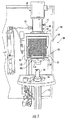
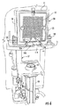
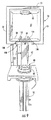
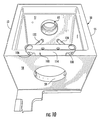
最初に図1を参照すると、2010年8月12日に出願され「COMBUSTION FURNACE AUTO CLEANER」と題する米国仮特許出願番号61/373,014号に詳細に示された自動洗浄機構30を有する誘導炉組立体20を含む分析装置10が示されている。該米国仮特許出願の開示内容を本明細書の一部を構成するものとしてここに援用する。分析装置の構成要素自体は、ミシガン州セントジョーセフのLeco Corporationから入手可能な炭素硫黄分析装置モデル番号CS600に使用されているものと類似したものとすることができる。図1には、図2〜図5にも示された誘導炉の構成要素を露出させるためにカバーシュラウドを取り外した分析装置10が示されている。脱着可能な自動洗浄装置組立体30は、加熱フィルタ組立体40にバイオネット接続によって取り外し可能に取り付けられ、加熱フィルタ組立体40は、燃焼ハウジング50の上壁51に65で示す箇所で封止可能に固定される。ハウジング50は、更に、図7〜図12で最もよく見えるように、側壁53及び55、境界後壁57、及び底壁58を有する。ハウジング50は、ハウジング50を含む分析装置10の構造的ベース17に取り付けられている。炉ハウジング50の前面は、迅速に取外し可能な扉52によって取り囲まれ、この扉52は、図2に見られるように、取り外されたときに誘導コイル61を露出する。この誘導コイル61は、垂直方向に移動可能なペデスタル12によって燃焼管60の高温ゾーンに導入されたときに、セラミックるつぼ14(図1)内に保持された分析試料を加熱するように従来の方式で燃焼管60(図7)を取り囲む。管60は、フィルタ組立体40の下端に、上側封止組立体65によって従来の方式で封止可能に結合される。試料保持るつぼ14を保持するためのペデスタル12(図1)は、カップ状下側封止組立体16上に位置決めされ、組立体16に結合された空気シリンダ18とシリンダロッド22(図7)によって燃焼管60内に上昇されたり、下降されたりする。図1に示された位置では、シリンダロッド22は、シリンダ18内の下側後退位置にある。
Referring initially to FIG. 1, an induction furnace having an
燃焼管ベース組立体80(図3〜図5)が、管60の下端を下側封止組立体16に封止可能に結合し、その結果、試料の燃焼中に、組立体16のガス入口から酸素が上方に流れて、分析のために燃焼副生成物をガス出口13(図1)内に押し流す。また、酸素入口15及び入口ランスまでの適切な通路を介して酸素が燃焼管60の上端に供給され、燃焼中にるつぼ14内に酸素が導かれる。ハウジング50はカム式ロック組立体100を有する。このカム式ロック組立体100は、後述するように、ベース組立体80と協力して燃焼管60を燃焼ハウジング50の底壁の下側から容易に引き出すことを可能にする。
A combustion tube base assembly 80 (FIGS. 3-5) sealably couples the lower end of the
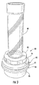
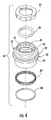
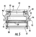
燃焼管60は、Leco Corporationから入手可能な従来の石英燃焼管である部品番号619−590−775又はその同等品でよい。図3〜図5に見られるように、燃焼管は、図3に見られるように、燃焼管60を受け入れるための中央開口81を有するほぼ円筒状のカラー82を含むベース組立体80を有する。カラー82の上縁の近くには、Oリングシール84を収容する環状くぼみ83がある。燃焼管をカラー82内に封止可能に保持するために、燃焼管がカラー82に挿入された後でロックキャップ85がカラー82にねじ式に被せられ、Oリングシールを圧縮する。カラー82は、ベース組立体80を下側封止組立体16上に密閉する第2のOリング88を収容する内部環状くぼみ87を有する下側円筒状スリーブ86を備える。更に、組立体80は、カラー82の環状くぼみ91の内に位置決めされた金属RFIシールド89と第3の封止Oリング78(図14と図15)を有する。
The
カラー82はカム90を有し、このカム90は、外側環状垂直面92と、この垂直に延在する環状面92から約45°の角度で上方内側に面取りされた上側面取り面94と、面92から約45°の角度で内側下方に面取りされた下側面取り面96とを備える。従って、2つ面は、(図14に関して後述するように)90°スロット107内に嵌るように約90°の角度をなす。カラー82は、また、図14に見られるように燃焼管が取付けロック位置にあるときに底壁58の下面と係合するように、炉ハウジング底壁58の開口59より大きい直径を有する環状フランジ93を有する。そのように規定されたカム90は、前述したような燃焼管60とベース組立体80を組み合わせたもの(図3に示されている)をロックしロック解除するために、カム式組立体100のカムピン106及び108と相互係合する。
The
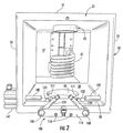
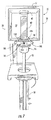
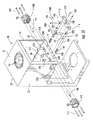
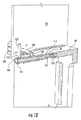
図7〜図15は、炉ハウジング50からの燃焼管60の取り外しを示し、分かりやすくするために、カム式燃焼管取り付け機構の説明に不要な誘導コイルや他の部品は、これらの図から削除されている。また、図7〜図10では、これらの図が、主に取り外しと交換の際の燃焼管の動きを例示するためのものなので、カム式組立体100を自動的に操作するための空気アクチュエータは示されていない。図7〜図9は、カム式組立体100がロック解除位置に動かされて、図8に見られるように燃焼管を炉ハウジング50の底壁58の円形開口59(図10)を介して下降させることを可能にした後でシリンダ18が後退位置に移動されたときの燃焼管の動きを示す。燃焼管60とベース組立体80は、図9に見られるような位置に下降されたとき、燃焼管60とベース組立体80を下側封止組立体16から持ち上げ、ロックリング85を緩めて燃焼管60をベース組立体80から取り外せるようにし、燃焼管60を新しい燃焼管と交換することができる。カム式組立体100は、燃焼管ベース組立体80のカム90と協力して解放可能なロック機構を構成して、燃焼管60をロック可能に保持し、或いは炉ハウジング50の下から解放する。
7-15 illustrate the removal of the
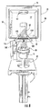
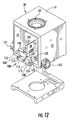
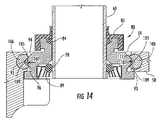
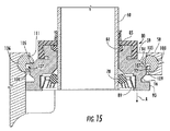
組立体100は、図11〜図15に最もよく見えるように、燃焼ハウジング50から燃焼管60(及び、取り付けられたベース組立体80)を手動又は自動でロック解除するために使用される。燃焼ハウジング50の底壁58は、機構100のカムピン106及び108を回転可能に収容する1対の円筒状のめくら穴102及び104を有する。穴102及び104は、底壁58の開口59の両側の縁と交わるように形状とサイズが決められ、ピン106及び108の内向き縁のほぼV字形の90°スロット107が、開口59の切り欠いた(truncated)円筒側壁内の開口111から露出している。ばね110及び112が、ピン106及び108の内側端と係合し、ピン106及び108は、取付板114によって穴102及び104内に保持され、取付板114は、取付板114の穴120を通る締結具118によって底壁58の前面116に固定されている。1対の手動ハンドル122及び124がそれぞれ、カムピン106,108の端部近くの穴123及び125にピン留めされ、その結果、例えば図7〜図10に見られるようにオペレータがハンドル122及び124を内方に回すことによって、ピン106及び108をロック解除位置に手動で回転させることができる。ばね110,112は、ハンドル122,124を板114の内向面の凹状くぼみ113,115内に付勢して、ハンドル122,124を解除可能なロック位置に付勢する(図1及び図12〜図14)。図15に示されたロック解除位置では、ハンドルは、くぼみ113,115から外れるように回転され、ピン106及び108の90°スロット107を、スロット107の面105及び109(通常は、組立体80のカム90の面取り面94及び96と係合している)がそれぞれ、カム90を解放する位置に回転させ、これにより、図15に見られるように、燃焼管60とベース組立体80を、図9に示された位置にあるときに取り外すために、矢印Aで示された方向に下降させることを可能にする。また、円筒状ピン106及び108の面105及びその先端がカム90の面取り面94を押し、ベース組立体80と燃焼管60が底壁50から下方に外れるのを支援する。
The
カム式燃焼管解放組立体100は、オペレータがハンドル122,124を互いに近づく方向に回転させてピン106,108を回転させ、燃焼管60を解放することにより手動で操作されてもよいが、この操作は自動化されてもよい。そのような目的のために、底壁58は、底壁58の開口59の前方に1対の弧状くぼみ130及び132を有し、これらのくぼみ130及び132は、穴102及び104と連通して、ピン106及び108上の、アクチュエータピン131及び133を受ける穴127及び129(図11)を露出させる。ピン131,133は、底壁58から上方に延在し、図12と13に最もよく見られるように、それぞれ空気圧シリンダ141及び143のアクチュエータロッド140及び142と係合することができる。シリンダ141及び143は、ハウジング50の側壁53及び55のくぼみ150内に、締結具145によって従来の方式で固定される。従って、ピン106及び108を図14に示されたロック位置から図15に示されたロック解除位置まで回転させるために、カム式組立体100をハンドル122又は124を持つオペレータによって手動で操作してもよく、シリンダ141及び143の動作によって電気的に操作してもよい。ロック解除位置にあるとき、シリンダ18を利用して燃焼管とその封止組立体を下降させ、燃焼管60を図9に示された位置まで下げることができ、そこで、燃焼管60を炉ハウジングから取り外して交換することができる。
The cam-type combustion
燃焼管を新しい管と交換しベース組立体80に取り付けた後で、シリンダ18を逆に作動させ、燃焼管を図8に見られるような上方向に、図1に示されたロック位置まで上昇させることができる。燃焼管が開口59内を上昇すると、カム90の面94がピン106及び108上のカム面105と係合し、燃焼管60が図15の矢印Aと反対方向に移動されるとき、ピン106及び108を回転させ、ロックピン106,108を図14に示されたロック位置に移動させる。この位置で、ピン106,108の面105,109は、それぞれのカム90の面取り面94,96と係合し、炉ハウジング50の底壁58の下側面と係合するベース組立体のフランジ93によって燃焼管60を適所に確実に保持する。図15に見られるように、ピン106及び108は、開口59の円筒状側壁のスロット111から、カム90と係合するのに十分なだけ突出する。
After the combustion tube is replaced with a new tube and attached to the
本明細書に記載されたような本発明の好ましい実施形態に対する様々な変更は、特許請求の範囲によって定義されたような本発明の趣旨又は範囲から逸脱することなく行うことができることは当業者にとって明らかであろう。 It will be apparent to those skilled in the art that various modifications to the preferred embodiments of the invention as described herein can be made without departing from the spirit or scope of the invention as defined by the claims. It will be clear.
10 分析装置
16 下側封止組立体
20 燃焼炉
50 炉ハウジング
58 底壁
59 開口
60 燃焼管
DESCRIPTION OF
Claims (19)
概略円筒状の燃焼管と、
前記燃焼管に結合された下側封止組立体であって、前記底壁の前記開口を介して前記燃焼管を前記炉ハウジング内に上昇させると共に前記燃焼管を前記炉ハウジングから下降させるために上昇位置と下降位置との間で移動可能な下側封止組立体とを有する炉。 Comprising a furnace housing having a bottom wall with an opening for receiving the combustion tube, a furnace for the analyzer,
And Overview Once the cylindrical combustion tube,
A combined lower sealing assembly into said combustion tube, the combustion tube with increasing the combustion tube into the furnace housing through said opening of said bottom wall for lowering from the furnace housing furnace that having a and a lower sealing assembly movable between raised and lowered positions.
前記ピン収容穴内に回転可能に取り付けられた1対のピンであって、前記開口の方を向くと共に前記ピン穴と前記開口の交点で露出したV字形スロットをそれぞれ有する1対のピンと、
前記燃焼管の下側端に取り付けられテーパ面を備えたカムであって、前記ピンが第1の位置にあるときにテーパ面が前記ピンの前記V字形スロットと係合して記燃焼管を前記炉ハウジング内の適所に保持し、前記ピンが第2の位置に回転されたときにテーパ面が前記ピンから外れて前記燃焼管を解放するカムと
を更に有する、請求項1に記載の炉。 Extends the bottom wall, and a pin receiving hole of a pair of intersecting the both sides of the side walls of the opening,
A pair of pins rotatably mounted in the pin receiving hole, each having a V-shaped slot facing the opening and exposed at the intersection of the pin hole and the opening;
A cam having a tapered surface attached to a lower end of the combustion tube, wherein the tapered surface engages with the V-shaped slot of the pin when the pin is in the first position. The furnace of claim 1, further comprising a cam held in place within the furnace housing and having a tapered surface disengaged from the pin to release the combustion tube when the pin is rotated to a second position. .
Applications Claiming Priority (3)
| Application Number | Priority Date | Filing Date | Title |
|---|---|---|---|
| US24573209P | 2009-09-25 | 2009-09-25 | |
| US61/245,732 | 2009-09-25 | ||
| PCT/US2010/050160 WO2011038203A1 (en) | 2009-09-25 | 2010-09-24 | Easily removable combustion tube |
Publications (3)
| Publication Number | Publication Date |
|---|---|
| JP2013506113A JP2013506113A (en) | 2013-02-21 |
| JP2013506113A5 JP2013506113A5 (en) | 2013-09-05 |
| JP5750445B2 true JP5750445B2 (en) | 2015-07-22 |
Family
ID=43780349
Family Applications (1)
| Application Number | Title | Priority Date | Filing Date |
|---|---|---|---|
| JP2012531060A Active JP5750445B2 (en) | 2009-09-25 | 2010-09-24 | Furnace with easy to remove combustion tube |
Country Status (5)
| Country | Link |
|---|---|
| US (4) | US8884193B2 (en) |
| JP (1) | JP5750445B2 (en) |
| CN (1) | CN102511003B (en) |
| DE (1) | DE112010003790B4 (en) |
| WO (1) | WO2011038203A1 (en) |
Families Citing this family (13)
| Publication number | Priority date | Publication date | Assignee | Title |
|---|---|---|---|---|
| US8884193B2 (en) | 2009-09-25 | 2014-11-11 | Leco Corporation | Easily removable combustion tube |
| US9541287B2 (en) * | 2010-08-12 | 2017-01-10 | Leco Corporation | Combustion furnace auto cleaner |
| US8377397B2 (en) | 2011-03-02 | 2013-02-19 | Leco Corporation | Combustion tube |
| USD678791S1 (en) | 2011-09-01 | 2013-03-26 | Leco Corporation | Combustion tube |
| WO2015064631A1 (en) * | 2013-10-29 | 2015-05-07 | 株式会社堀場製作所 | Analysis device |
| US10545106B2 (en) | 2014-03-21 | 2020-01-28 | Leco Corporation | Combustion tube |
| CN106568735A (en) * | 2016-10-25 | 2017-04-19 | 福建紫金矿冶测试技术有限公司 | High-frequency infrared carbon and sulfur analyzer standard sample selection and working curve production method |
| CN206875940U (en) | 2017-05-24 | 2018-01-12 | 尤根牙科医疗科技(北京)有限公司 | A kind of dual-purpose sintering furnace |
| CN107023283A (en) * | 2017-05-27 | 2017-08-08 | 成都理工大学 | Combustion system for combustion in situ simulated test |
| EP4204801A1 (en) * | 2020-08-28 | 2023-07-05 | Horiba Tocadero GmbH | Industrial water analysis device and support therefor |
| CN112415126A (en) * | 2020-11-24 | 2021-02-26 | 华北电力科学研究院有限责任公司 | Fixing device and elemental analyzer provided with the fixing device |
| CN113465385B (en) * | 2021-05-13 | 2023-02-17 | 中国地质科学院水文地质环境地质研究所 | Detachable organic carbon high-temperature closed combustion system and application thereof |
| CN113774316B (en) * | 2021-09-30 | 2023-08-29 | 德亚炉业科技江苏有限公司 | Controllable atmosphere well type multipurpose furnace and application thereof |
Family Cites Families (22)
| Publication number | Priority date | Publication date | Assignee | Title |
|---|---|---|---|---|
| US2332943A (en) * | 1940-08-26 | 1943-10-26 | Hevi Duty Electric Co | Carbon combustion furnace |
| US2809100A (en) * | 1951-05-12 | 1957-10-08 | Lab Equipment Corp | Combustion analyzer |
| US2686211A (en) * | 1952-07-12 | 1954-08-10 | Allegheny Ludlum Steel | Combustion furnace |
| US2923464A (en) * | 1955-10-17 | 1960-02-02 | Dorr Oliver Inc | Centrifuge construction |
| US3002819A (en) * | 1958-02-20 | 1961-10-03 | Phillips Petroleum Co | Apparatus for testing fuels |
| US3058814A (en) * | 1959-08-13 | 1962-10-16 | Lab Equipment Corp | Apparatus for combustion analysis |
| BE787397A (en) * | 1971-08-12 | 1973-02-12 | Siderurgie Fse Inst Rech | DEGAZING CHAMBER |
| US3923464A (en) * | 1972-09-25 | 1975-12-02 | Leco Corp | Combustion apparatus for analytical instruments |
| JPS5514424A (en) * | 1978-07-17 | 1980-01-31 | Hitachi Ltd | Apparatus for connecting quartz tube |
| US4234541A (en) * | 1979-03-02 | 1980-11-18 | Leco Corporation | Combustion chamber cleaning apparatus |
| US4417346A (en) * | 1981-06-29 | 1983-11-22 | The Kanthal Corporation | High temperature melting furnace |
| JPS5848858A (en) * | 1981-09-17 | 1983-03-22 | Horiba Ltd | Automatic metal analyzing device |
| JPS61106612U (en) * | 1984-12-19 | 1986-07-07 | ||
| US4793640A (en) * | 1986-10-30 | 1988-12-27 | United Technologies Electro Systems, Inc. | Cam-actuated electric door lock |
| US5720091A (en) * | 1996-04-09 | 1998-02-24 | L&P Property Management | Indexer with cam-actuated lock |
| DE19800853A1 (en) * | 1998-01-13 | 1999-07-15 | Ald Vacuum Techn Gmbh | Closed, evacuable crucible for inductive melting or overheating of metals, alloys or other electrically conductive materials |
| JP4157215B2 (en) * | 1999-03-15 | 2008-10-01 | 株式会社堀場製作所 | Gas extraction furnace for elemental analyzer |
| US6803237B2 (en) * | 2000-01-25 | 2004-10-12 | Woods Hole Oceanographic Institution | Sequential processing reaction vessel for chemical fractionation and analysis |
| CN2520510Y (en) * | 2002-01-31 | 2002-11-13 | 国电环境保护研究所 | Instrument for quick analysis of total sulfur of coal |
| CN1254674C (en) * | 2004-08-03 | 2006-05-03 | 上海德凯仪器有限公司 | Burning device of infrared carbon-sulphur analyzer |
| CN1869709A (en) * | 2006-06-09 | 2006-11-29 | 孙笑欢 | Combined instrument of carbon-sulfur automatic analysing method and multi-metal element analysing |
| US8884193B2 (en) | 2009-09-25 | 2014-11-11 | Leco Corporation | Easily removable combustion tube |
-
2010
- 2010-09-24 US US12/889,628 patent/US8884193B2/en active Active
- 2010-09-24 JP JP2012531060A patent/JP5750445B2/en active Active
- 2010-09-24 CN CN201080042407.0A patent/CN102511003B/en not_active Expired - Fee Related
- 2010-09-24 WO PCT/US2010/050160 patent/WO2011038203A1/en not_active Ceased
- 2010-09-24 DE DE112010003790.6T patent/DE112010003790B4/en active Active
-
2014
- 2014-10-07 US US14/508,315 patent/US9874399B2/en active Active
- 2014-10-07 US US14/508,368 patent/US9879915B2/en active Active
- 2014-10-07 US US14/508,428 patent/US9874400B2/en active Active
Also Published As
| Publication number | Publication date |
|---|---|
| US9874400B2 (en) | 2018-01-23 |
| US20110075696A1 (en) | 2011-03-31 |
| JP2013506113A (en) | 2013-02-21 |
| DE112010003790B4 (en) | 2015-09-17 |
| US9874399B2 (en) | 2018-01-23 |
| US20150023383A1 (en) | 2015-01-22 |
| US20150036713A1 (en) | 2015-02-05 |
| CN102511003A (en) | 2012-06-20 |
| WO2011038203A1 (en) | 2011-03-31 |
| CN102511003B (en) | 2014-08-20 |
| US9879915B2 (en) | 2018-01-30 |
| US20150036714A1 (en) | 2015-02-05 |
| US8884193B2 (en) | 2014-11-11 |
| DE112010003790T5 (en) | 2012-11-08 |
Similar Documents
| Publication | Publication Date | Title |
|---|---|---|
| JP5750445B2 (en) | Furnace with easy to remove combustion tube | |
| US8377397B2 (en) | Combustion tube | |
| US4286287A (en) | Irradiation specimen installation apparatus with television inspection | |
| EP1712728B1 (en) | Pipe elevator and method | |
| CN209615130U (en) | Tool for cleaning the valve body of a control valve | |
| CN107076615B (en) | Leucoscope | |
| JP5587263B2 (en) | Combustion furnace automatic cleaning machine | |
| KR101638003B1 (en) | Decontamination equipment for remove contaminating radioactive substance of nuclear reactor pipe | |
| TW202432273A (en) | Gas purge plug and system for easy installation of the gas purge plug in a metallurgical vessel | |
| DE102020103947A1 (en) | CVD reactor and method of handling a process chamber ceiling plate | |
| EP1331205A2 (en) | Latch mechanism for a forehearth feeder tube lift system | |
| SE503761C2 (en) | Solvent Extraction Device | |
| US11772581B2 (en) | Transfer ports for confinement gloveboxes and related methods | |
| CN223050670U (en) | Gas boiler fume emission monitoring device | |
| CN222068543U (en) | Catalytic reaction device | |
| US20210254829A1 (en) | Interchangeable seal head system | |
| KR101178522B1 (en) | Latching device of pusher car | |
| JPH11248887A (en) | Sodium removal device in through hole | |
| JP2000035498A (en) | Sodium removal device in through hole |
Legal Events
| Date | Code | Title | Description |
|---|---|---|---|
| A521 | Request for written amendment filed |
Free format text: JAPANESE INTERMEDIATE CODE: A523 Effective date: 20130717 |
|
| A621 | Written request for application examination |
Free format text: JAPANESE INTERMEDIATE CODE: A621 Effective date: 20130717 |
|
| A977 | Report on retrieval |
Free format text: JAPANESE INTERMEDIATE CODE: A971007 Effective date: 20140616 |
|
| A131 | Notification of reasons for refusal |
Free format text: JAPANESE INTERMEDIATE CODE: A131 Effective date: 20140722 |
|
| A601 | Written request for extension of time |
Free format text: JAPANESE INTERMEDIATE CODE: A601 Effective date: 20141021 |
|
| A602 | Written permission of extension of time |
Free format text: JAPANESE INTERMEDIATE CODE: A602 Effective date: 20141028 |
|
| A521 | Request for written amendment filed |
Free format text: JAPANESE INTERMEDIATE CODE: A523 Effective date: 20141120 |
|
| TRDD | Decision of grant or rejection written | ||
| A01 | Written decision to grant a patent or to grant a registration (utility model) |
Free format text: JAPANESE INTERMEDIATE CODE: A01 Effective date: 20150421 |
|
| A61 | First payment of annual fees (during grant procedure) |
Free format text: JAPANESE INTERMEDIATE CODE: A61 Effective date: 20150518 |
|
| R150 | Certificate of patent or registration of utility model |
Ref document number: 5750445 Country of ref document: JP Free format text: JAPANESE INTERMEDIATE CODE: R150 |
|
| R250 | Receipt of annual fees |
Free format text: JAPANESE INTERMEDIATE CODE: R250 |
|
| R250 | Receipt of annual fees |
Free format text: JAPANESE INTERMEDIATE CODE: R250 |
|
| R250 | Receipt of annual fees |
Free format text: JAPANESE INTERMEDIATE CODE: R250 |
|
| R250 | Receipt of annual fees |
Free format text: JAPANESE INTERMEDIATE CODE: R250 |
|
| R250 | Receipt of annual fees |
Free format text: JAPANESE INTERMEDIATE CODE: R250 |
|
| R250 | Receipt of annual fees |
Free format text: JAPANESE INTERMEDIATE CODE: R250 |
|
| R250 | Receipt of annual fees |
Free format text: JAPANESE INTERMEDIATE CODE: R250 |
|
| R250 | Receipt of annual fees |
Free format text: JAPANESE INTERMEDIATE CODE: R250 |