JP5750431B2 - Pants-type disposable diaper and method for manufacturing the same - Google Patents
Pants-type disposable diaper and method for manufacturing the same Download PDFInfo
- Publication number
- JP5750431B2 JP5750431B2 JP2012284061A JP2012284061A JP5750431B2 JP 5750431 B2 JP5750431 B2 JP 5750431B2 JP 2012284061 A JP2012284061 A JP 2012284061A JP 2012284061 A JP2012284061 A JP 2012284061A JP 5750431 B2 JP5750431 B2 JP 5750431B2
- Authority
- JP
- Japan
- Prior art keywords
- side seal
- diaper
- exterior body
- type disposable
- disposable diaper
- Prior art date
- Legal status (The legal status is an assumption and is not a legal conclusion. Google has not performed a legal analysis and makes no representation as to the accuracy of the status listed.)
- Active
Links
Images
Classifications
-
- A—HUMAN NECESSITIES
- A61—MEDICAL OR VETERINARY SCIENCE; HYGIENE
- A61F—FILTERS IMPLANTABLE INTO BLOOD VESSELS; PROSTHESES; DEVICES PROVIDING PATENCY TO, OR PREVENTING COLLAPSING OF, TUBULAR STRUCTURES OF THE BODY, e.g. STENTS; ORTHOPAEDIC, NURSING OR CONTRACEPTIVE DEVICES; FOMENTATION; TREATMENT OR PROTECTION OF EYES OR EARS; BANDAGES, DRESSINGS OR ABSORBENT PADS; FIRST-AID KITS
- A61F13/00—Bandages or dressings; Absorbent pads
- A61F13/15—Absorbent pads, e.g. sanitary towels, swabs or tampons for external or internal application to the body; Supporting or fastening means therefor; Tampon applicators
- A61F13/15577—Apparatus or processes for manufacturing
- A61F13/15804—Plant, e.g. involving several steps
-
- A—HUMAN NECESSITIES
- A61—MEDICAL OR VETERINARY SCIENCE; HYGIENE
- A61F—FILTERS IMPLANTABLE INTO BLOOD VESSELS; PROSTHESES; DEVICES PROVIDING PATENCY TO, OR PREVENTING COLLAPSING OF, TUBULAR STRUCTURES OF THE BODY, e.g. STENTS; ORTHOPAEDIC, NURSING OR CONTRACEPTIVE DEVICES; FOMENTATION; TREATMENT OR PROTECTION OF EYES OR EARS; BANDAGES, DRESSINGS OR ABSORBENT PADS; FIRST-AID KITS
- A61F13/00—Bandages or dressings; Absorbent pads
- A61F13/15—Absorbent pads, e.g. sanitary towels, swabs or tampons for external or internal application to the body; Supporting or fastening means therefor; Tampon applicators
- A61F13/45—Absorbent pads, e.g. sanitary towels, swabs or tampons for external or internal application to the body; Supporting or fastening means therefor; Tampon applicators characterised by the shape
- A61F13/49—Absorbent pads, e.g. sanitary towels, swabs or tampons for external or internal application to the body; Supporting or fastening means therefor; Tampon applicators characterised by the shape specially adapted to be worn around the waist, e.g. diapers, nappies
- A61F13/496—Absorbent pads, e.g. sanitary towels, swabs or tampons for external or internal application to the body; Supporting or fastening means therefor; Tampon applicators characterised by the shape specially adapted to be worn around the waist, e.g. diapers, nappies in the form of pants or briefs
- A61F13/4963—Absorbent pads, e.g. sanitary towels, swabs or tampons for external or internal application to the body; Supporting or fastening means therefor; Tampon applicators characterised by the shape specially adapted to be worn around the waist, e.g. diapers, nappies in the form of pants or briefs characterized by the seam
-
- B—PERFORMING OPERATIONS; TRANSPORTING
- B29—WORKING OF PLASTICS; WORKING OF SUBSTANCES IN A PLASTIC STATE IN GENERAL
- B29C—SHAPING OR JOINING OF PLASTICS; SHAPING OF MATERIAL IN A PLASTIC STATE, NOT OTHERWISE PROVIDED FOR; AFTER-TREATMENT OF THE SHAPED PRODUCTS, e.g. REPAIRING
- B29C65/00—Joining or sealing of preformed parts, e.g. welding of plastics materials; Apparatus therefor
- B29C65/02—Joining or sealing of preformed parts, e.g. welding of plastics materials; Apparatus therefor by heating, with or without pressure
- B29C65/14—Joining or sealing of preformed parts, e.g. welding of plastics materials; Apparatus therefor by heating, with or without pressure using wave energy, i.e. electromagnetic radiation, or particle radiation
- B29C65/16—Laser beams
- B29C65/1629—Laser beams characterised by the way of heating the interface
- B29C65/1648—Laser beams characterised by the way of heating the interface radiating the edges of the parts to be joined
-
- B—PERFORMING OPERATIONS; TRANSPORTING
- B29—WORKING OF PLASTICS; WORKING OF SUBSTANCES IN A PLASTIC STATE IN GENERAL
- B29C—SHAPING OR JOINING OF PLASTICS; SHAPING OF MATERIAL IN A PLASTIC STATE, NOT OTHERWISE PROVIDED FOR; AFTER-TREATMENT OF THE SHAPED PRODUCTS, e.g. REPAIRING
- B29C65/00—Joining or sealing of preformed parts, e.g. welding of plastics materials; Apparatus therefor
- B29C65/02—Joining or sealing of preformed parts, e.g. welding of plastics materials; Apparatus therefor by heating, with or without pressure
- B29C65/14—Joining or sealing of preformed parts, e.g. welding of plastics materials; Apparatus therefor by heating, with or without pressure using wave energy, i.e. electromagnetic radiation, or particle radiation
- B29C65/16—Laser beams
- B29C65/1629—Laser beams characterised by the way of heating the interface
- B29C65/1654—Laser beams characterised by the way of heating the interface scanning at least one of the parts to be joined
- B29C65/1661—Laser beams characterised by the way of heating the interface scanning at least one of the parts to be joined scanning repeatedly, e.g. quasi-simultaneous laser welding
-
- B—PERFORMING OPERATIONS; TRANSPORTING
- B29—WORKING OF PLASTICS; WORKING OF SUBSTANCES IN A PLASTIC STATE IN GENERAL
- B29C—SHAPING OR JOINING OF PLASTICS; SHAPING OF MATERIAL IN A PLASTIC STATE, NOT OTHERWISE PROVIDED FOR; AFTER-TREATMENT OF THE SHAPED PRODUCTS, e.g. REPAIRING
- B29C65/00—Joining or sealing of preformed parts, e.g. welding of plastics materials; Apparatus therefor
- B29C65/02—Joining or sealing of preformed parts, e.g. welding of plastics materials; Apparatus therefor by heating, with or without pressure
- B29C65/14—Joining or sealing of preformed parts, e.g. welding of plastics materials; Apparatus therefor by heating, with or without pressure using wave energy, i.e. electromagnetic radiation, or particle radiation
- B29C65/16—Laser beams
- B29C65/1696—Laser beams making use of masks
-
- B—PERFORMING OPERATIONS; TRANSPORTING
- B29—WORKING OF PLASTICS; WORKING OF SUBSTANCES IN A PLASTIC STATE IN GENERAL
- B29C—SHAPING OR JOINING OF PLASTICS; SHAPING OF MATERIAL IN A PLASTIC STATE, NOT OTHERWISE PROVIDED FOR; AFTER-TREATMENT OF THE SHAPED PRODUCTS, e.g. REPAIRING
- B29C65/00—Joining or sealing of preformed parts, e.g. welding of plastics materials; Apparatus therefor
- B29C65/74—Joining or sealing of preformed parts, e.g. welding of plastics materials; Apparatus therefor by welding and severing, or by joining and severing, the severing being performed in the area to be joined, next to the area to be joined, in the joint area or next to the joint area
- B29C65/747—Joining or sealing of preformed parts, e.g. welding of plastics materials; Apparatus therefor by welding and severing, or by joining and severing, the severing being performed in the area to be joined, next to the area to be joined, in the joint area or next to the joint area using other than mechanical means
- B29C65/7473—Joining or sealing of preformed parts, e.g. welding of plastics materials; Apparatus therefor by welding and severing, or by joining and severing, the severing being performed in the area to be joined, next to the area to be joined, in the joint area or next to the joint area using other than mechanical means using radiation, e.g. laser, for simultaneously welding and severing
-
- B—PERFORMING OPERATIONS; TRANSPORTING
- B29—WORKING OF PLASTICS; WORKING OF SUBSTANCES IN A PLASTIC STATE IN GENERAL
- B29C—SHAPING OR JOINING OF PLASTICS; SHAPING OF MATERIAL IN A PLASTIC STATE, NOT OTHERWISE PROVIDED FOR; AFTER-TREATMENT OF THE SHAPED PRODUCTS, e.g. REPAIRING
- B29C66/00—General aspects of processes or apparatus for joining preformed parts
- B29C66/01—General aspects dealing with the joint area or with the area to be joined
- B29C66/05—Particular design of joint configurations
- B29C66/10—Particular design of joint configurations particular design of the joint cross-sections
- B29C66/11—Joint cross-sections comprising a single joint-segment, i.e. one of the parts to be joined comprising a single joint-segment in the joint cross-section
- B29C66/112—Single lapped joints
- B29C66/1122—Single lap to lap joints, i.e. overlap joints
-
- B—PERFORMING OPERATIONS; TRANSPORTING
- B29—WORKING OF PLASTICS; WORKING OF SUBSTANCES IN A PLASTIC STATE IN GENERAL
- B29C—SHAPING OR JOINING OF PLASTICS; SHAPING OF MATERIAL IN A PLASTIC STATE, NOT OTHERWISE PROVIDED FOR; AFTER-TREATMENT OF THE SHAPED PRODUCTS, e.g. REPAIRING
- B29C66/00—General aspects of processes or apparatus for joining preformed parts
- B29C66/70—General aspects of processes or apparatus for joining preformed parts characterised by the composition, physical properties or the structure of the material of the parts to be joined; Joining with non-plastics material
- B29C66/72—General aspects of processes or apparatus for joining preformed parts characterised by the composition, physical properties or the structure of the material of the parts to be joined; Joining with non-plastics material characterised by the structure of the material of the parts to be joined
- B29C66/723—General aspects of processes or apparatus for joining preformed parts characterised by the composition, physical properties or the structure of the material of the parts to be joined; Joining with non-plastics material characterised by the structure of the material of the parts to be joined being multi-layered
-
- B—PERFORMING OPERATIONS; TRANSPORTING
- B29—WORKING OF PLASTICS; WORKING OF SUBSTANCES IN A PLASTIC STATE IN GENERAL
- B29C—SHAPING OR JOINING OF PLASTICS; SHAPING OF MATERIAL IN A PLASTIC STATE, NOT OTHERWISE PROVIDED FOR; AFTER-TREATMENT OF THE SHAPED PRODUCTS, e.g. REPAIRING
- B29C66/00—General aspects of processes or apparatus for joining preformed parts
- B29C66/70—General aspects of processes or apparatus for joining preformed parts characterised by the composition, physical properties or the structure of the material of the parts to be joined; Joining with non-plastics material
- B29C66/72—General aspects of processes or apparatus for joining preformed parts characterised by the composition, physical properties or the structure of the material of the parts to be joined; Joining with non-plastics material characterised by the structure of the material of the parts to be joined
- B29C66/729—Textile or other fibrous material made from plastics
- B29C66/7294—Non woven mats, e.g. felt
- B29C66/72941—Non woven mats, e.g. felt coated
-
- B—PERFORMING OPERATIONS; TRANSPORTING
- B29—WORKING OF PLASTICS; WORKING OF SUBSTANCES IN A PLASTIC STATE IN GENERAL
- B29C—SHAPING OR JOINING OF PLASTICS; SHAPING OF MATERIAL IN A PLASTIC STATE, NOT OTHERWISE PROVIDED FOR; AFTER-TREATMENT OF THE SHAPED PRODUCTS, e.g. REPAIRING
- B29C66/00—General aspects of processes or apparatus for joining preformed parts
- B29C66/80—General aspects of machine operations or constructions and parts thereof
- B29C66/83—General aspects of machine operations or constructions and parts thereof characterised by the movement of the joining or pressing tools
- B29C66/834—General aspects of machine operations or constructions and parts thereof characterised by the movement of the joining or pressing tools moving with the parts to be joined
- B29C66/8341—Roller, cylinder or drum types; Band or belt types; Ball types
- B29C66/83431—Roller, cylinder or drum types; Band or belt types; Ball types rollers, cylinders or drums cooperating with bands or belts
- B29C66/83433—Roller, cylinder or drum types; Band or belt types; Ball types rollers, cylinders or drums cooperating with bands or belts the contact angle between said rollers, cylinders or drums and said bands or belts being a non-zero angle
-
- B—PERFORMING OPERATIONS; TRANSPORTING
- B29—WORKING OF PLASTICS; WORKING OF SUBSTANCES IN A PLASTIC STATE IN GENERAL
- B29C—SHAPING OR JOINING OF PLASTICS; SHAPING OF MATERIAL IN A PLASTIC STATE, NOT OTHERWISE PROVIDED FOR; AFTER-TREATMENT OF THE SHAPED PRODUCTS, e.g. REPAIRING
- B29C66/00—General aspects of processes or apparatus for joining preformed parts
- B29C66/80—General aspects of machine operations or constructions and parts thereof
- B29C66/83—General aspects of machine operations or constructions and parts thereof characterised by the movement of the joining or pressing tools
- B29C66/834—General aspects of machine operations or constructions and parts thereof characterised by the movement of the joining or pressing tools moving with the parts to be joined
- B29C66/8341—Roller, cylinder or drum types; Band or belt types; Ball types
- B29C66/83431—Roller, cylinder or drum types; Band or belt types; Ball types rollers, cylinders or drums cooperating with bands or belts
- B29C66/83435—Roller, cylinder or drum types; Band or belt types; Ball types rollers, cylinders or drums cooperating with bands or belts said rollers, cylinders or drums being hollow
-
- A—HUMAN NECESSITIES
- A61—MEDICAL OR VETERINARY SCIENCE; HYGIENE
- A61F—FILTERS IMPLANTABLE INTO BLOOD VESSELS; PROSTHESES; DEVICES PROVIDING PATENCY TO, OR PREVENTING COLLAPSING OF, TUBULAR STRUCTURES OF THE BODY, e.g. STENTS; ORTHOPAEDIC, NURSING OR CONTRACEPTIVE DEVICES; FOMENTATION; TREATMENT OR PROTECTION OF EYES OR EARS; BANDAGES, DRESSINGS OR ABSORBENT PADS; FIRST-AID KITS
- A61F13/00—Bandages or dressings; Absorbent pads
- A61F13/15—Absorbent pads, e.g. sanitary towels, swabs or tampons for external or internal application to the body; Supporting or fastening means therefor; Tampon applicators
- A61F13/84—Accessories, not otherwise provided for, for absorbent pads
- A61F2013/8497—Accessories, not otherwise provided for, for absorbent pads having decorations or indicia means
-
- B—PERFORMING OPERATIONS; TRANSPORTING
- B29—WORKING OF PLASTICS; WORKING OF SUBSTANCES IN A PLASTIC STATE IN GENERAL
- B29C—SHAPING OR JOINING OF PLASTICS; SHAPING OF MATERIAL IN A PLASTIC STATE, NOT OTHERWISE PROVIDED FOR; AFTER-TREATMENT OF THE SHAPED PRODUCTS, e.g. REPAIRING
- B29C65/00—Joining or sealing of preformed parts, e.g. welding of plastics materials; Apparatus therefor
- B29C65/02—Joining or sealing of preformed parts, e.g. welding of plastics materials; Apparatus therefor by heating, with or without pressure
- B29C65/14—Joining or sealing of preformed parts, e.g. welding of plastics materials; Apparatus therefor by heating, with or without pressure using wave energy, i.e. electromagnetic radiation, or particle radiation
- B29C65/16—Laser beams
- B29C65/1603—Laser beams characterised by the type of electromagnetic radiation
- B29C65/1612—Infrared [IR] radiation, e.g. by infrared lasers
- B29C65/1619—Mid infrared radiation [MIR], e.g. by CO or CO2 lasers
-
- B—PERFORMING OPERATIONS; TRANSPORTING
- B29—WORKING OF PLASTICS; WORKING OF SUBSTANCES IN A PLASTIC STATE IN GENERAL
- B29C—SHAPING OR JOINING OF PLASTICS; SHAPING OF MATERIAL IN A PLASTIC STATE, NOT OTHERWISE PROVIDED FOR; AFTER-TREATMENT OF THE SHAPED PRODUCTS, e.g. REPAIRING
- B29C66/00—General aspects of processes or apparatus for joining preformed parts
- B29C66/01—General aspects dealing with the joint area or with the area to be joined
- B29C66/05—Particular design of joint configurations
- B29C66/10—Particular design of joint configurations particular design of the joint cross-sections
- B29C66/13—Single flanged joints; Fin-type joints; Single hem joints; Edge joints; Interpenetrating fingered joints; Other specific particular designs of joint cross-sections not provided for in groups B29C66/11 - B29C66/12
- B29C66/137—Beaded-edge joints or bead seals
-
- B—PERFORMING OPERATIONS; TRANSPORTING
- B29—WORKING OF PLASTICS; WORKING OF SUBSTANCES IN A PLASTIC STATE IN GENERAL
- B29C—SHAPING OR JOINING OF PLASTICS; SHAPING OF MATERIAL IN A PLASTIC STATE, NOT OTHERWISE PROVIDED FOR; AFTER-TREATMENT OF THE SHAPED PRODUCTS, e.g. REPAIRING
- B29C66/00—General aspects of processes or apparatus for joining preformed parts
- B29C66/70—General aspects of processes or apparatus for joining preformed parts characterised by the composition, physical properties or the structure of the material of the parts to be joined; Joining with non-plastics material
- B29C66/71—General aspects of processes or apparatus for joining preformed parts characterised by the composition, physical properties or the structure of the material of the parts to be joined; Joining with non-plastics material characterised by the composition of the plastics material of the parts to be joined
-
- B—PERFORMING OPERATIONS; TRANSPORTING
- B29—WORKING OF PLASTICS; WORKING OF SUBSTANCES IN A PLASTIC STATE IN GENERAL
- B29C—SHAPING OR JOINING OF PLASTICS; SHAPING OF MATERIAL IN A PLASTIC STATE, NOT OTHERWISE PROVIDED FOR; AFTER-TREATMENT OF THE SHAPED PRODUCTS, e.g. REPAIRING
- B29C66/00—General aspects of processes or apparatus for joining preformed parts
- B29C66/70—General aspects of processes or apparatus for joining preformed parts characterised by the composition, physical properties or the structure of the material of the parts to be joined; Joining with non-plastics material
- B29C66/73—General aspects of processes or apparatus for joining preformed parts characterised by the composition, physical properties or the structure of the material of the parts to be joined; Joining with non-plastics material characterised by the intensive physical properties of the material of the parts to be joined, by the optical properties of the material of the parts to be joined, by the extensive physical properties of the parts to be joined, by the state of the material of the parts to be joined or by the material of the parts to be joined being a thermoplastic or a thermoset
- B29C66/739—General aspects of processes or apparatus for joining preformed parts characterised by the composition, physical properties or the structure of the material of the parts to be joined; Joining with non-plastics material characterised by the intensive physical properties of the material of the parts to be joined, by the optical properties of the material of the parts to be joined, by the extensive physical properties of the parts to be joined, by the state of the material of the parts to be joined or by the material of the parts to be joined being a thermoplastic or a thermoset characterised by the material of the parts to be joined being a thermoplastic or a thermoset
- B29C66/7392—General aspects of processes or apparatus for joining preformed parts characterised by the composition, physical properties or the structure of the material of the parts to be joined; Joining with non-plastics material characterised by the intensive physical properties of the material of the parts to be joined, by the optical properties of the material of the parts to be joined, by the extensive physical properties of the parts to be joined, by the state of the material of the parts to be joined or by the material of the parts to be joined being a thermoplastic or a thermoset characterised by the material of the parts to be joined being a thermoplastic or a thermoset characterised by the material of at least one of the parts being a thermoplastic
- B29C66/73921—General aspects of processes or apparatus for joining preformed parts characterised by the composition, physical properties or the structure of the material of the parts to be joined; Joining with non-plastics material characterised by the intensive physical properties of the material of the parts to be joined, by the optical properties of the material of the parts to be joined, by the extensive physical properties of the parts to be joined, by the state of the material of the parts to be joined or by the material of the parts to be joined being a thermoplastic or a thermoset characterised by the material of the parts to be joined being a thermoplastic or a thermoset characterised by the material of at least one of the parts being a thermoplastic characterised by the materials of both parts being thermoplastics
-
- B—PERFORMING OPERATIONS; TRANSPORTING
- B29—WORKING OF PLASTICS; WORKING OF SUBSTANCES IN A PLASTIC STATE IN GENERAL
- B29L—INDEXING SCHEME ASSOCIATED WITH SUBCLASS B29C, RELATING TO PARTICULAR ARTICLES
- B29L2031/00—Other particular articles
- B29L2031/48—Wearing apparel
- B29L2031/4871—Underwear
- B29L2031/4878—Diapers, napkins
Landscapes
- Engineering & Computer Science (AREA)
- Health & Medical Sciences (AREA)
- Mechanical Engineering (AREA)
- Physics & Mathematics (AREA)
- Optics & Photonics (AREA)
- Life Sciences & Earth Sciences (AREA)
- Electromagnetism (AREA)
- Toxicology (AREA)
- Heart & Thoracic Surgery (AREA)
- Biomedical Technology (AREA)
- Epidemiology (AREA)
- Vascular Medicine (AREA)
- Animal Behavior & Ethology (AREA)
- General Health & Medical Sciences (AREA)
- Public Health (AREA)
- Veterinary Medicine (AREA)
- Textile Engineering (AREA)
- Botany (AREA)
- Manufacturing & Machinery (AREA)
- Absorbent Articles And Supports Therefor (AREA)
Description
本発明は、サイドシール部を有するパンツ型使い捨ておむつに関する。 The present invention relates to a pants-type disposable diaper having a side seal portion.
従来、パンツ型使い捨ておむつとしては、吸収性本体と、該吸収性本体の非肌当接面側に配されて該吸収性本体を固定している外装体とを備え、且つ前身頃の左右両側縁と後身頃の左右両側縁とが接合されて一対のサイドシール部、ウエスト開口部及び一対のレッグ開口部が形成されているものが汎用されている。 Conventionally, a pants-type disposable diaper includes an absorbent main body and an exterior body that is arranged on the non-skin contact surface side of the absorbent main body and fixes the absorbent main body, and both left and right sides of the front body In general, a pair of side seal parts, a waist opening part, and a pair of leg opening parts are formed by joining the edge and the right and left side edges of the back body.
通常、パンツ型使い捨ておむつを着用者の身体から取り外す際には、サイドシール部において該おむつを前身頃と後身頃とに引き裂くところ、おむつ使用後の交換の際に着用者の身体に排泄物等の汚れが付かないようにするためには、使用後のおむつを速やかに身体から取り外す必要があり、そのためには、サイドシール部は縦方向に容易に引き裂くことができるようになっていることが好ましい。サイドシール部の引き裂き性に関し、例えば特許文献1には、おむつの着用中に外れたりしない程度の十分な接合強度と引き裂き性の向上との両立等の観点から、サイドシール部に3段階の接合強度を併存させることが記載されている。
Normally, when removing a pants-type disposable diaper from the wearer's body, the side seal part tears the diaper into the front body and the back body, excrement etc. on the wearer's body when replacing the diaper after use In order to prevent the dirt from sticking, it is necessary to quickly remove the diaper after use from the body, and for that purpose, the side seal part must be easily torn in the vertical direction. preferable. Regarding tearability of the side seal part, for example,
また従来、使い捨ておむつや生理用ナプキン等の吸収性物品の製造工程においては、重ね合わせたシートどうしの接合にヒートロール装置が汎用されており、一般に、サイドシール部は、後述するように、ヒートロール装置を用いて形成される。また、他の接合方法として、レーザー光を用いて溶着する方法も知られている。例えば特許文献2には、複数枚のシートが重ねられたシート積層体を、周面にレーザー光透過性部を有する回転ロールの該周面に沿った形状に変形させて搬送しながら、該シート積層体に対して該回転ロールの内側からレーザー光を照射し、該シート積層体内のシートどうしを融着させる方法が記載されている。
Conventionally, in the manufacturing process of absorbent articles such as disposable diapers and sanitary napkins, a heat roll device has been widely used for joining stacked sheets. Generally, the side seal portion is heated as described later. It is formed using a roll device. As another bonding method, a method of welding using laser light is also known. For example, in
パンツ型使い捨ておむつは、通常、次のような工程を経て製造される。即ち、複数のおむつが一方向(搬送方向)に連なってなるおむつ連続体(例えば、図5の符号10で示すおむつ連続体)を製造し、このおむつ連続体における、サイドシール部形成予定部位にて互いに重なり合う前身頃(前身頃を形成する外装体)と後身頃(後身頃を形成する外装体)とを、ヒートロール装置等の接合手段により互いに接合した後、その接合部をカッター等の切断手段により切断することにより、個々のおむつに分断する工程を経て製造される。こうして製造される従来のパンツ型使い捨ておむつのサイドシール部(前記切断手段による切断によって生じた前記接合部の切断縁部)は、前身頃の左右両側縁と後身頃の左右両側縁とが合掌状に重なり合って形成されており、その合掌状部分の頂部が周辺部よりも外方に突出しているので、目視により容易に認識できる。
A pants-type disposable diaper is usually manufactured through the following steps. That is, a diaper continuous body (for example, a diaper continuous body indicated by
前述したパンツ型使い捨ておむつの製造工程において、おむつ連続体の分断を、レーザー光や加熱圧着法等の熱源を用いて実施した場合は、おむつ連続体が個々に分断(溶断)されるのと同時に、その分断によって生じた複数枚の外装体の切断縁部どうしが融着して、一対のサイドシール部を有するパンツ型使い捨ておむつが連続的に製造されるようになる。このような、分断と溶着とが同時に実施される工程を経て得られたサイドシール部は、前述した製造工程を経て得られた合掌状のサイドシール部に比して、外装体どうしの接合幅が狭いため、おむつの着用感を向上させ得る一方で、合掌状のサイドシール部のようにおむつの外方に突出して形成されていないため、おむつの着用状態又は自然状態(収縮状態)において目視による視認性が低く、その存在を目視により認識するのが難しい場合がある。特に、おむつの着用時においてサイドシール部の目視による視認性が低いと、例えばおむつの使用後に、着用者である乳幼児からその保護者(例えば母親)がおむつを取り外す際にサイドシール部を見つけ難く、おむつの取り外し作業に手間取るおそれがある。特許文献1及び2には、このような、分断と溶着とが同時に実施される工程を経て得られたサイドシール部やそれに固有の課題は記載されていない。
In the manufacturing process of the pants-type disposable diaper described above, when the diaper continuous body is cut using a heat source such as a laser beam or a thermocompression bonding method, the diaper continuous body is cut (melted) individually. The cut edge portions of the plurality of exterior bodies generated by the division are fused together, and a pants-type disposable diaper having a pair of side seal portions is continuously manufactured. The side seal part obtained through the process in which the splitting and welding are performed at the same time is compared with the joint width between the exterior bodies as compared with the palm-shaped side seal part obtained through the manufacturing process described above. Because it is narrow, it can improve the wearing feeling of the diaper, but it is not formed protruding outward from the diaper like the palm-shaped side seal part, so it is visible in the wearing state or natural state (contracted state) of the diaper. The visibility due to is low, and it may be difficult to visually recognize its presence. In particular, when the visibility of the side seal portion is low when the diaper is worn, it is difficult to find the side seal portion when the guardian (for example, mother) removes the diaper from the infant who is the wearer after using the diaper, for example. There is a risk of taking time to remove the diaper.
従って、本発明は、サイドシール部の目視による視認性が高いパンツ型使い捨ておむつ及びその製造方法に関する。 Therefore, this invention relates to the underpants type disposable diaper with high visibility by visual observation of a side seal part, and its manufacturing method.
本発明は、吸収性本体と、該吸収性本体の非肌当接面側に配されて該吸収性本体を固定している外装体とを備え、且つ前身頃における該外装体の左右両側縁部と後身頃における該外装体の左右両側縁部とが接合されて一対のサイドシール部、ウエスト開口部及び一対のレッグ開口部が形成されているパンツ型使い捨ておむつであって、前記サイドシール部は、前記おむつの着用時において目視による視認性が低く、該サイドシール部の目視による視認性を高め得るサイドシール部視認性向上手段を該サイドシール部の近傍に具備しているパンツ型使い捨ておむつを提供するものである。 The present invention comprises an absorbent main body and an exterior body that is disposed on the non-skin contact surface side of the absorbent main body and fixes the absorbent main body, and both left and right edges of the exterior body in the front body A pants-type disposable diaper in which a pair of side seal portions, a waist opening portion, and a pair of leg opening portions are formed by joining the left and right side edges of the exterior body at the back portion and the back body, wherein the side seal portion Is a pants-type disposable diaper having a side seal portion visibility improving means in the vicinity of the side seal portion, which has low visibility when worn on the diaper and can improve the visibility of the side seal portion. Is to provide.
また本発明は、前記パンツ型使い捨ておむつの製造方法であって、帯状の前記外装体に前記吸収性本体を固定する本体固定工程と、前記吸収性本体が固定された帯状の前記外装体の前身頃側と後身頃側とを重ね合わせ、重ね合わされた該外装体におけるサイドシール部の形成予定部位を加圧状態にする重合加圧工程と、加圧状態にある前記サイドシール部の形成予定部位を分断するのと同時に、その分断によって生じた加圧状態にある複数枚の前記外装体の切断縁部どうしを融着させて前記サイドシール部を形成するサイドシール部形成工程と、を有し、前記本体固定工程の終了後から前記サイドシール部形成工程の終了前までに、前記外装体に前記サイドシール部視認性向上手段を付与する、パンツ型使い捨ておむつの製造方法を提供するものである。 The present invention also relates to a method for manufacturing the pants-type disposable diaper, wherein a main body fixing step of fixing the absorbent main body to the belt-shaped outer package, and a front body of the belt-shaped outer package to which the absorbent main body is fixed. A polymerization pressurizing step in which the side seal portion is formed in a pressurized state in the outer body that is overlapped with the back side and the back body side, and the side seal portion scheduled to be formed in the pressurized state And a side seal part forming step of forming the side seal part by fusing the cut edges of the plurality of exterior bodies in a pressurized state generated by the division. Provided is a method for manufacturing a pants-type disposable diaper, wherein the side seal part visibility improving means is provided to the exterior body from the end of the main body fixing process to the end of the side seal part forming process. Than is.
本発明によれば、サイドシール部の目視による視認性が高いパンツ型使い捨ておむつが提供される。 ADVANTAGE OF THE INVENTION According to this invention, the underpants type disposable diaper with high visibility by visual observation of a side seal part is provided.
本発明の主たる特長の1つは、吸収性本体と、該吸収性本体の非肌当接面側に配されて該吸収性本体を固定している外装体とを備え、且つ前身頃の左右両側縁と後身頃の左右両側縁とが接合されて一対のサイドシール部、ウエスト開口部及び一対のレッグ開口部が形成されているパンツ型使い捨ておむつにおいて、サイドシール部の目視による視認性を高め得るサイドシール部視認性向上手段を採用した点にある。このサイドシール部視認性向上手段の採用は、前述したように、パンツ型使い捨ておむつの製造工程において、おむつ連続体(帯状の外装体)の所定箇所(サイドシール部形成予定部位)に例えばレーザー光を照射する等して、おむつ連続体(帯状の外装体)を個々に分断するのと同時に、その分断によって生じた複数枚の外装体の切断縁部どうしを融着して、一対のサイドシール部を形成する場合に特に有効である。このような、「外装体の分断と融着とが同時に実施される工程を経て得られたサイドシール部」は、おむつの着用時(着用状態)において目視による視認性が低く、特に、おむつを取り外すために該サイドシール部を引き裂く観点から、サイドシール部視認性向上手段を採用し、おむつの着用時における該サイドシール部の目視による視認性を向上させることは有効である。また、このようなサイドシール部は、おむつの自然状態(収縮状態)においても目視による視認性が低いサイドシール部でもありるため、着用する際のおむつの前後及び左右の見極めのためにも、サイドシール部視認性向上手段を採用し、おむつの自然状態(着用前の収縮状態)における該サイドシール部の目視による視認性を向上させることは有効である。以下には、先ず、本発明に係るサイドシール部視認性向上手段が採用され得る、基本技術について説明し、次いで、該サイドシール部視認性向上手段について説明する。基本技術として説明する後述するおむつ1は、本発明に係るサイドシール部視認性向上手段を具備しておらず、本発明の範囲外のものである。
One of the main features of the present invention includes an absorbent main body and an exterior body that is disposed on the non-skin contact surface side of the absorbent main body and fixes the absorbent main body. In a pants-type disposable diaper in which the side edges and the left and right side edges of the back body are joined to form a pair of side seals, a waist opening, and a pair of leg openings, the visibility of the side seals is improved. The side seal part visibility improving means to be obtained is employed. As described above, the side seal portion visibility improving means is used in a manufacturing process of a pants-type disposable diaper, for example, a laser beam at a predetermined portion (a portion where the side seal portion is scheduled to be formed) of the diaper continuous body (band-shaped exterior body). The diaper continuous body (strip-shaped exterior body) is divided into individual pieces by irradiating, for example, and at the same time, the cut edges of the multiple exterior bodies produced by the division are fused together to form a pair of side seals This is particularly effective when forming the portion. Such a “side seal part obtained through a process in which the outer body is divided and fused at the same time” has low visibility when worn (in a worn state), and in particular, a diaper. From the viewpoint of tearing the side seal portion for removal, it is effective to employ a side seal portion visibility improving means to improve the visual visibility of the side seal portion when the diaper is worn. Moreover, since such a side seal part is also a side seal part with low visibility by eye even in the natural state (contracted state) of the diaper, for the purpose of determining the front and rear of the diaper and the right and left when wearing it, It is effective to employ a side seal portion visibility improving means to improve the visibility of the side seal portion in the natural state (contracted state before wearing) of the diaper. In the following, first, a basic technique in which the side seal portion visibility improving means according to the present invention can be adopted will be described, and then the side seal portion visibility improving means will be described. A
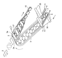
[基本技術]
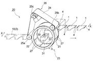
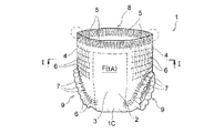
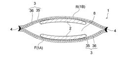
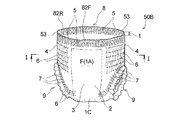
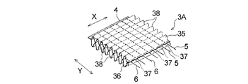
図1には、本発明のパンツ型使い捨ておむつの製造方法に適用可能な、レーザー式接合装置を用いたパンツ型使い捨ておむつの製造方法の概略が示されている。このレーザー式接合装置を用いた製造方法の製造目的物であるおむつ1は、図2〜図4に示すように、吸収性本体2と、該吸収性本体2の非肌当接面側に配されて該吸収性本体2を固定している外装体3とを備え、且つ前身頃F(腹側部1A)における外装体3の縦方向Xに沿う左右両側縁部A1,A1と後身頃R(背側部1B)における外装体3の縦方向Xに沿う左右両側縁部B1,B1とが接合されて一対のサイドシール部4,4、ウエスト開口部8及び一対のレッグ開口部9,9が形成されているパンツ型使い捨ておむつである。サイドシール部4は、複数枚の外装体3の縁部が重なった状態で融着して形成されている。サイドシール部は、その幅が5mm以下であり、または3mm以下であり、あるいは2mm以下に形成されている。
[Basic technology]
The outline of the manufacturing method of the underpants type disposable diaper using a laser type joining device applicable to the manufacturing method of the underpants type disposable diaper of the present invention is shown in FIG. As shown in FIGS. 2 to 4, the
おむつ1は、図4に示す如き展開且つ伸長状態の平面視において、着用者の前後方向に相当する縦方向Xとこれに直交する横方向Yとを有している。おむつ1は、着用時に股下部に配される股下部1C並びにその縦方向Xの前後に位置する腹側部1A及び背側部1Bに区分することができる。股下部1Cは、その縦方向Xに沿う左右両側縁部にレッグ開口部9,9形成用の凹欠部が形成されている領域である。また、おむつ1は、図4に示すように、おむつ1を縦方向Xに二分する仮想中心線CLを境にして、前身頃Fと後身頃Rとに区分することができる。
The
尚、本明細書において、肌当接面は、使い捨ておむつ又はその構成部材(例えば吸収性本体2)における、使い捨ておむつの着用時に着用者の肌側に向けられる面であり、非肌当接面は、使い捨ておむつ又はその構成部材における、使い捨ておむつの着用時に肌側とは反対側(着衣側)に向けられる面である。また、縦方向Xは、使い捨ておむつ又はその構成部材である吸収性本体2の長辺に沿う方向(長手方向)に一致し、横方向Yは、使い捨ておむつ又はその構成部材である吸収性本体2の幅方向に一致する。
In addition, in this specification, a skin contact surface is a surface turned to a wearer's skin side at the time of wear of a disposable diaper in a disposable diaper or its structural member (for example, absorbent main body 2), and a non-skin contact surface Is the surface of the disposable diaper or its component that is directed to the side opposite to the skin side (clothing side) when the disposable diaper is worn. Moreover, the vertical direction X corresponds to the direction (longitudinal direction) along the long side of the absorbent
吸収性本体2は、図4に示すように、一方向(縦方向X)が相対的に長い縦長の形状を有しており、肌当接面を形成する表面シート(図示せず)と、非肌当接面を形成する裏面シート(図示せず)と、これら両シート間に介在配置された液保持性の吸収体(図示せず)とを具備し、該吸収体は、縦方向Xと同方向に長い形状を有している。吸収性本体2は、その長手方向を、展開且つ伸長状態(図4に示す状態)におけるおむつ1の縦方向Xに一致させて、外装体3の中央部に公知の接合手段(接着剤等)により接合されている。ここで、展開且つ伸長状態とは、サイドシール部を引き剥がして、おむつを展開状態とし、その展開状態のおむつを、各部の弾性部材を伸長させて、設計寸法(弾性部材の影響を一切排除した状態で平面状に広げたときの寸法と同じ)となるまで拡げた状態をいう。
As shown in FIG. 4, the absorbent
外装体3は、図2〜図4に示すように、おむつ1の外面(外装体3の非肌当接面)を形成する外層シート35と、該外層シート35の内面側に配され、おむつ1の内面(外装体3の肌当接面)を形成する内層シート36と、両シート35,36間に接着剤(図示せず)により固定された複数本の糸状又は帯状の弾性部材5,6,7とを含んで構成されている。両シート35,36間は、所定部位において接着剤又はヒートシール等(図示せず)によって接合されている。
As shown in FIGS. 2 to 4, the
外装体3(外層シート35、内層シート36)は、樹脂材を含み、該樹脂材を主成分として形成されている。外装体3(外層シート35、内層シート36)の一例として、樹脂材としてポリエチレン、ポリエチレンテレフタレート、ポリプロピレン等の熱融着性の合成樹脂を含み、不織布、フィルム、不織布とフィルムとのラミネートシート等からなるものが挙げられる。不織布としては、エアースルー不織布、ヒートロール不織布、スパンレース不織布、スパンボンド不織布、メルトブローン不織布等が挙げられる。
The exterior body 3 (the
おむつ1の製造方法は、帯状の外装体3(外層シート35、内層シート36)に吸収性本体2を固定する本体固定工程と、吸収性本体2が固定された帯状の外装体3の前身頃側と後身頃側とを重ね合わせ(帯状の外装体3の長手方向に沿う一側縁側と他側縁側とを重ね合わせ)、重ね合わされた外装体3におけるサイドシール部の形成予定部位を加圧状態にする重合加圧工程と、加圧状態にあるサイドシール部の形成予定部位を分断するのと同時に、その分断によって生じた加圧状態にある複数枚の外装体の切断縁部3どうしを融着させてサイドシール部4を形成するサイドシール部形成工程とを有している。
The manufacturing method of the
より具体的には、おむつ1の製造方法においては、図5に示すように、前記重合加圧工程において、帯状の外装体3(外層シート35、内層シート36)をその幅方向に折り畳むことにより、吸収性本体2が固定された帯状の外装体3の前身頃側と後身頃側とを重ね合わせ、それによって、「サイドシール部が形成されていないパンツ型使い捨ておむつの前駆体が一方向に連なってなる、おむつ連続体10」を別途製造する。そして、前記サイドシール部形成工程において、このおむつ連続体10(帯状の外装体3)を、図1に示すように、レーザー光30の照射により、個々に分断(溶断)するのと同時に、その分断によって生じた加圧状態にある複数枚の外装体3(外層シート35、内層シート36)の切断縁部どうしを融着して、一対のサイドシール部4,4を有する外装体3を具備するパンツ型使い捨ておむつ1を連続的に製造する。
More specifically, in the manufacturing method of the
先ず、図5に示すように、原反ロール(図示せず)から連続的に供給される帯状の外層シート35と、原反ロール(図示せず)から連続的に供給される帯状の内層シート36との間に、ウェストギャザーを形成するウエスト部弾性部材5、胴回りギャザーを形成する胴回り部弾性部材6及びレッグギャザーを形成するレッグ部弾性部材7を、所定の伸長率に伸長させた伸長状態で各々複数本配する。このとき、レッグ部弾性部材7は、シートの流れ方向とは直交して往復運動する公知の揺動ガイド(図示せず)を介して、所定の脚周りパターンを形成しながら配される。また、帯状の外層シート35及び帯状の内層シート36には、それらを重ね合わせる前に、両シート35,36の何れか一方又は双方の相対向する面の所定部位に、接着剤塗工機(図示せず)によりホットメルト型接着剤を塗工する。尚、ウエスト部弾性部材5、胴回り部弾性部材6等の弾性部材が、両シート35,36における、レーザー光の照射によって分断される部分(サイドシール部4の形成予定部分)(図6中符号10Cで示す分断予定部分)を跨ぐように伸長状態で配されている場合、その分断後の該弾性部材の大幅な縮みや該弾性部材の抜け等の不都合を回避するために、該部分及びその近傍に接着剤を塗工しておくことが好ましい。ウエスト部弾性部材5及び胴回り部弾性部材6には、両シート35,36間に配される前に、接着剤塗工機(図示せず)によりホットメルト型接着剤を間欠的に塗工しても良い。
First, as shown in FIG. 5, a strip-shaped
そして、図5に示すように、一対のニップロール11,11の間に、ウエスト部弾性部材5、胴回り部弾性部材6及びレッグ部弾性部材7を伸長状態で挟み込んだ帯状の外層シート35及び帯状の内層シート36を送り込んで加圧することにより、帯状シート35,36間に複数本の弾性部材5,6,7が伸長状態で配された帯状の外装体3を形成する。この外装体3の形成工程においては、隣り合う2本の胴回り部弾性部材6,6間において帯状の外層シート35と帯状の内層シート36とを接合する複数の接合部(図示せず)を、凸ロールとこれに対応するアンビルロール等の接合手段(図示せず)を用いて形成する。その後、必要に応じ、弾性部材プレカット手段(図示せず)を用いて、後述する吸収性本体2を配する位置に対応させて、複数本の胴回り部弾性部材6及び複数本のレッグ部弾性部材7を押圧して、収縮機能が発現されないように個々複数個に分断する。前記弾性部材プレカット手段としては、例えば、特開2002−253605号公報に記載の複合伸縮部材の製造方法に用いる弾性部材分断部等が挙げられる。
And as shown in FIG. 5, between the pair of nip rolls 11, 11, a belt-shaped
次いで、図5に示すように、別工程で製造された吸収性本体2に予めホットメルト接着剤等の接着剤を塗工し、該吸収性本体2を90度回転させて、帯状の外装体3を構成する内層シート36上に間欠的に供給して固定する(本体固定工程)。尚、吸収性本体固定用の接着剤は、吸収性本体2ではなく、内層シート36における吸収性本体2の配置予定位置に予め塗工しても良い。
Next, as shown in FIG. 5, an adhesive such as a hot melt adhesive is applied in advance to the absorbent
次いで、図5に示すように、吸収性本体2が配置された帯状の外装体3におけるレッグ部弾性部材7で環状に囲まれた環状部の内側にレッグホールLO’を形成する。このレッグホール形成工程は、ロータリーカッター、レーザーカッター等の従来からこの種の物品の製造方法における手法と同様の手法を用いて実施することができる。尚、図示の態様においては、帯状の外装体3に吸収性本体2を配置した後にレッグホールを形成しているが、吸収性本体2の配置前にレッグホールを形成しても良い。
Next, as shown in FIG. 5, a leg hole LO ′ is formed inside the annular portion that is annularly surrounded by the leg
次いで、帯状の外装体3をその幅方向(外装体3の搬送方向と直交する方向)に折り畳む。より具体的には、図5に示すように、帯状の外装体3の搬送方向に沿う両側部3a,3aを、吸収性本体2の長手方向両端部(図4に示す吸収性本体2の縦方向Xの両端部)を覆うように折り返して吸収性本体2の長手方向両端部を固定した後、外装体3を吸収性本体2と共にその幅方向に2つ折りする(重合加圧工程)。こうして、おむつ連続体10が得られる。
Next, the belt-shaped
次いで、こうして別途製造されたおむつ連続体10に対して、図1に示すように、レーザー式接合装置20を用いてレーザー光を照射して一対のサイドシール部4,4を形成し(サイドシール部形成工程)、一対の該サイドシール部4を有する外装体3を具備するパンツ型使い捨ておむつ1を連続的に製造する。
Next, as shown in FIG. 1, the diaper
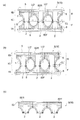
レーザー式接合装置20について説明すると、レーザー式接合装置20は、図1に示すように、矢印A方向に回転駆動される円筒状の支持部材21を備えた中空の円筒ロール23と、無端状の加圧ベルト24(押さえ部材)を備えたベルト式加圧装置26とを備えている。レーザー式接合装置20は、支持部材21(円筒ロール23の周面部)と加圧ベルト24との間隔を増減調整できる間隔調整機構(図示せず)を有し、該間隔の調整により、支持部材21と加圧ベルト24とによって、おむつ連続体10に加える圧力を適宜調整することができる。
The
支持部材21は、円筒ロール23の周面部(被加工物との当接部)を形成しており、円筒ロール23の左右両側縁部を形成する一対の環状の枠体22,22間に挟持固定されている。支持部材21は、環状の枠体22の周長と同じ長さの単一の環状部材から構成されており、鉄、アルミニウム、ステンレス鋼、銅等の金属材料又はセラミックス等の耐熱性を有する材料からなる。
The
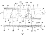
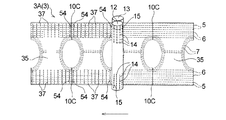
支持部材21は、レーザー光が通過可能な光通過部を有している。支持部材21は、図1及び図6に示すように、光通過部として、該支持部材21を厚み方向に貫通するスリット状の開口部27を有している。開口部27は、平面視して矩形形状を有し、その長手方向を支持部材21の幅方向(図6(a)中符号Xで示す方向。円筒ロール23の回転軸と平行な方向。)に一致させて、円筒状の支持部材21の周方向に所定間隔を置いて複数形成されている。支持部材21は、開口部27ではレーザー光を通過させる一方、開口部27以外の部分ではレーザー光を通過(透過)させない。支持部材21に開口部27を形成する方法としては、1)支持部材21の所定箇所にエッチング、パンチング、レーザー加工等により開口部27を穿設する方法の他、2)支持部材21として、単一の環状部材に代えて、湾曲した矩形形状の部材を複数用い、それら複数の部材を、一対の枠体22,22間に、該枠体22の周方向に所定間隔を置いて配置する方法が挙げられる。前記2)の方法では、隣接する2つの部材の間隔が、スリット状の開口部27となる。尚、図6(a)中、符号27Aで示す部位(接合部形成用貫通孔)は、後述する本発明の第1実施態様において採用されているもので、ここでは説明しない。
The
支持部材21は、図6(b)に示すように、その外面(被加工物との当接面)に凹部28を有している。凹部28は、円筒状の支持部材21の周方向に所定間隔を置いて複数形成されており、隣接する2つの凹部28,28間に位置する領域(凸部)に、スリット状の開口部27が形成されている。開口部27は、前記凸部における円筒状の支持部材21の周方向の中央に形成されている。
As shown in FIG. 6B, the
このように、支持部材21の外面に凹部28が形成されていることにより、おむつ連続体10の厚みが均一でない場合は、該おむつ連続体10における相対的に厚みの大きい部分(例えば吸収性本体2の配置領域)が凹部28内に収まるように、該おむつ連続体10を支持部材21の外面上に導入することが可能となる。そして、おむつ連続体10をそのように支持部材21上に導入すると、図6(b)に示すように、おむつ連続体10における加圧ベルト24(押さえ部材)との当接面(他方の面10b)が略平坦となるため、加圧ベルト24をおむつ連続体10に押し付けたときに、おむつ連続体10における、開口部27が形成された前記凸部上に位置する部分〔図6中符号10Cで示す分断予定部分(サイドシール部4の形成予定部位)及びその近傍〕全体が、おむつ連続体10の支持部材21への所定のテンションでの巻きかけと加圧ベルト24とによって、所定の圧力でその厚み方向に均一に加圧されるようになる。こうしてレーザー光の照射による分断前から厚み方向に加圧された該部分に、レーザー光を照射して該部分を分断したときに、その分断された該部分を構成する複数枚のシートの切断縁部どうしをより確実に融着させることが可能となり、サイドシール部4(シール縁部)の融着強度の一層の向上が図られる。
Thus, when the thickness of the diaper
ベルト式加圧装置26は、無端状の加圧ベルト24(押さえ部材)及び該加圧ベルト24が架け渡された状態で回転する3本のロール25a,25b,25cを備えている。ロール25a,25b,25cは駆動ロールでも良く、円筒ロール23に連れ回りする従動ロールでも良い。加圧ベルト24は、ロール25a,25b,25cの何れか1以上を回転駆動として、又は円筒ロール23と連れ回りして、円筒ロール23(支持部材21)と同速度で移動する。支持部材21及び加圧ベルト24は、空冷、水冷等により温度を所定の温度範囲に維持することが好ましい。
The belt-
加圧ベルト24(押さえ部材)としては、加工時に発生する熱に耐えうる耐熱性を有する金属又は樹脂製のベルトを用いることができ、例えば、鉄、アルミニウム、ステンレス鋼等の金属材料からなるものを用いることができる。また、加圧ベルト24としては、通常、被加工物(おむつ連続体10)に対して照射されるレーザー光の透過性を有しないものが用いられるが、該透過性を有するものを用いることもできる。
As the pressure belt 24 (pressing member), a metal or resin belt having heat resistance capable of withstanding the heat generated during processing can be used, for example, a metal material such as iron, aluminum, stainless steel, or the like. Can be used. In addition, as the
図1に示すように、中空の円筒ロール23(支持部材21)の中空部には、該円筒ロール23の周面部を形成する支持部材21に向けてレーザー光30を照射する照射ヘッド31が設けられている。照射ヘッド31は、レーザー光30を自在に走査するガルバノスキャナ(モータ軸にミラーが付いた装置)であり、レーザー光30を円筒ロール23の回転軸と平行な方向(図6(a)中符号Xで示す方向)に進退させる機構、レーザー光30が支持部材21上のおむつ連続体10に当たる位置(照射点)を円筒ロール23の周方向に移動させる機構、円筒ロール23の周面上でレーザー光30のスポット径を一定にする機構等を備えている。照射ヘッド31は、レーザー光30の発生機能(光源)を備えておらず、レーザー光30は、円筒ロール23の外部に配された光源(図示せず)で発生し、該光源と照射ヘッド31とを結ぶ光通路(図示せず)を通って照射ヘッド31に到達するようになされている。レーザー照射機構は、このような構成を有することによって、レーザー光30の照射点を、円筒ロール23の周方向及び該周方向と直交する方向(図6(a)中符号Xで示す方向。円筒ロール23の回転軸と平行な方向。)の両方向に任意に移動させることができる。尚、図6中符号Xで示す、円筒ロール23の回転軸と平行な方向(円筒ロール23の周方向と直交する方向)は、図4中のおむつ1(吸収性本体2)の縦方向Xと同方向である。
As shown in FIG. 1, an
図1に示すように、おむつ連続体10は、図示しない案内ロール等によって、所定のテンションが掛けられた状態で、矢印A方向に回転駆動される円筒ロール23の周面部を形成する支持部材21の外面上に導入され、該支持部材21に巻き掛けられるようにして該円筒ロール23の回転によりその周方向に所定距離搬送された後、図示しない導出ロール及びニップロール等によって該支持部材21から離れる。このように、おむつ連続体10を、円筒ロール23の周面部を形成する支持部材21に所定のテンションで巻き掛け且つ加圧ベルト24によって圧接するようにして搬送することにより、おむつ連続体10における支持部材21と加圧ベルト24とに挟まれた部分及びその近傍は、レーザー光の照射による分断前からその厚み方向に加圧(圧縮)された状態となる。このため、おむつ連続体10が不織布を含む場合等に、該おむつ連続体10をより効率的に圧縮させることができ、結果として、斯かる圧縮中のおむつ連続体10に対してレーザー光を照射してこれを分断したときに、その分断された部分を構成する複数枚のシート(外装体3)の切断縁部どうしをより確実に融着させることが可能となり、サイドシール部4の融着強度の一層の向上が図られる。
As shown in FIG. 1, the diaper
おむつ連続体10が、支持部材21上に導入されてからこれを離れるまでの該支持部材21(円筒ロール23)の回転角度は、例えば、90度以上270度以下とすることができ、より好ましくは120度以上270度以下である。また、加圧ベルト24(押さえ部材)によりおむつ連続体10を支持部材21に圧接させる角度(圧接角度)の範囲は、円筒状の支持部材21(円筒ロール23)の周方向の全周に亘って圧接させる場合を360度とした場合に、90度以上270度以下であることが好ましく、より好ましくは120度以上270度以下である。
The rotation angle of the support member 21 (cylindrical roll 23) from when the diaper
図1及び図6に示す実施態様においては、おむつ連続体10を連続搬送しつつ、その一方の面10aを、円筒ロール23の周面部を形成し且つレーザー光30が通過可能なスリット状の開口部27(光通過部)を有する、支持部材21の外面に当接させ、支持部材21と加圧ベルト24(押さえ部材)とによって加圧状態となったおむつ連続体10(サイドシール部4の形成予定部位)に対して、支持部材21側から開口部27を介してレーザー光30を照射することにより、おむつ連続体10を分断するのと同時に、その分断によって生じた前記加圧状態にある複数枚のシート(外装体3)の切断縁部どうしを融着させて、サイドシール部4を形成する(サイドシール部形成工程)。
In the embodiment shown in FIG. 1 and FIG. 6, a slit-like opening through which the continuous surface of the
詳細には、図1及び図6に示すように、支持部材21に当接しているおむつ連続体10の他方の面10b(支持部材21との当接面である一方の面10aとは反対側の面)に、加圧ベルト24(押さえ部材)を押し付け、その状態のおむつ連続体10に対して、支持部材21側からスリット状の開口部27を介してレーザー光30を照射することにより、一対のサイドシール部4,4を有する外装体3を具備するおむつ1を連続的に製造する。このように、レーザー光30の照射は、支持部材21と加圧ベルト24とに挟まれることによって加圧状態(圧縮状態)にあるおむつ連続体10に対して行うことが、該照射によって生じた複数枚のシート(外装体3)の切断縁部どうしを確実に融着させて、サイドシール部4の融着強度を向上させる観点から好ましい。
Specifically, as shown in FIGS. 1 and 6, the
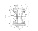
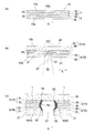
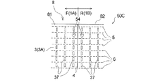
図7は、レーザー式接合装置20を用いておむつ連続体10(帯状のシート積層体)を分断するのと同時にサイドシール部4(シール縁部)を形成する様子を説明する図であり、図7(a)には、おむつ連続体10のレーザー光30による分断予定部分10C(サイドシール部4の形成予定部位)及びその近傍が模式的に示されている。図示の態様におけるおむつ連続体10の分断予定部分10Cは、図6(a)に示すように、おむつ連続体10の吸収性本体2が配置されていない領域における長手方向(搬送方向A)の中央である。斯かる分断予定部分10Cは、ウエスト開口部8(図2参照)の開口端部及びその近傍が、8枚のシートが重ねられた8層構造部分、それ以外の部分が、4枚のシートが重ねられた4層構造部分となっている。4層構造部分は、図7(a)に示すように、腹側部1Aにおける1枚の外装体3を構成する2枚のシート(外層シート35及び内層シート36)と、背側部1Bにおける1枚の外装体3を構成する同じく2枚のシート35,36とからなり、これら4枚のシートが積層されて構成されている。一方、8層構造部分は、前述したように、おむつ連続体10の製造時に帯状の外装体3の両側部3a,3aが吸収性本体2の長手方向両端部を覆うように折り返されている(図4及び図5参照)ことに起因して、腹側部1A及び背側部1Bそれぞれに外装体3が2枚存し且つこれら計4枚の外装体3,3が積層されているので、結果として8枚のシート35,36が積層されて構成されている。尚、4層構造部分及び8層構造部分それぞれにおいて、互いに重なり合うシート35,36間には、ウエスト部弾性部材5、胴回り部弾性部材6等の弾性部材が介在配置されている場合があるが、図7では、説明容易の観点から、該弾性部材の図示を省略している。以下、主として、4層構造部分について説明するが、特に断らない限り、8層構造部分も4層構造部分と同様に構成されサイドシール部4が形成される。
FIG. 7 is a diagram for explaining how the side seal portion 4 (seal edge) is formed at the same time as the diaper continuous body 10 (band-shaped sheet laminate) is divided using the
おむつ連続体10における4層構造の分断予定部分10Cにおいて、おむつ連続体10の一方の面10a(支持部材21との当接面)を構成する外層シート35及び一方の面10aを構成するシート以外のシート(内層シート36)は、何れか一方又は両方が、レーザー光30を吸収して発熱するシートである。図示の態様においては、分断予定部分10Cを構成する4枚のシート35,36の全てが、レーザー光30を吸収して発熱するシート(不織布)である。また、分断予定部分10C及びその近傍における互いに重なり合う外層シート35及び内層シート36の2枚のシート間は、レーザー光30の照射前において、接着剤等により接合されていても良く、全く接合されていなくても良い。
Other than the sheet constituting the
おむつ連続体10は、図7(b)に示すように、一方の面10aが支持部材21に当接し且つ分断予定部分10C(サイドシール部4の形成予定部位)がスリット状の開口部27上に位置するように、矢印A方向に回転する支持部材21上に導入されると共に、他方の面10bに加圧ベルト24(押さえ部材)が押し付けられることによって、矢印A方向に搬送されつつ厚み方向に加圧(圧縮)される。そして、斯かる搬送中且つ加圧状態の分断予定部分10Cに対して、支持部材21側から開口部27を介してレーザー光30が照射される。前述したように、レーザー光30の照射点は、円筒ロール23の周方向に任意に移動可能に構成されており、開口部27の該周方向に沿った移動に追従して移動するように設定されているので、該開口部27上に位置する分断予定部分10Cには、その搬送中にレーザー光30が一定時間連続的に照射される。
As shown in FIG. 7 (b), the diaper
4層構造の分断予定部分10Cにレーザー光30が照射されると、該分断予定部分10Cに存するシート35,36の形成材料(繊維等)は、レーザー光30の直射による発熱によって気化して消失し、該分断予定部分10Cの近傍に存する該形成材料は、レーザー光30によって間接的に熱せされて溶融する。その結果、図7(c)に示すように、4層構造の分断予定部分10Cが溶断されて、おむつ連続体10から1つの枚葉のシート積層体(おむつ前駆体)が切り分けられる形で、該おむつ連続体10が分断されるのと同時に、その分断によって生じた該枚葉のシート積層体における4枚のシート35,36の切断縁部どうし、及び、切り分けられた該おむつ連続体10における4枚のシート35,36の切断縁部どうしが、それぞれ融着する。これらの切断縁部どうしは、それぞれ、その形成前(レーザー光30の照射によるおむつ連続体10の分断前)から、支持部材21と加圧ベルト24とに挟まれることによって加圧状態(圧縮状態)とされていたものである。図示の態様のおむつの製造方法によれば、このように、一回のレーザー光の照射で、帯状の外装体3の分断と、その分断によって生じた2箇所の加圧状態にある外装体3の切断縁部どうしの融着とを同時に実施するため、2箇所の融着箇所を二回のレーザー光の照射で融着する方法に比べ、おおよそ半分のレーザー出力で融着と分断とを同一工程で実施でき、おむつ1を効率良く製造することができる。また、融着と分断とを同一工程で行えるため、シート(外装体)の切断縁部どうしが融着されていない非シール縁部が発生しないので、材料の削減効果もある。
When the
シート35,36の切断縁部は、レーザー光30の照射中及び照射終了直後は、発熱して溶融状態となっているが、レーザー光30の照射によっておむつ連続体10から切り分けられた1つの枚葉のおむつ前駆体及び該おむつ連続体10それぞれの、支持部材21と加圧ベルト24とによる加圧状態が保持されたまま、照射終了後からは外気によって速やかに冷却されて固化し、該切断縁部の形成材料(繊維等)が溶融一体化した融着部40となる。こうして、融着部40が形成されることによって、1個のおむつ1における一対のサイドシール部4,4のうちの一方が形成される。尚、必要に応じ、吸引装置、排気装置等の公知の冷却手段を用いてシート35,36の切断縁部を強制的に冷却し、融着部40の形成を促進しても良い。
The cut edges of the
こうして1箇所の分断予定部分10C(サイドシール部4の形成予定部位)が分断されると、レーザー光30は、その照射点が搬送方向Aとは逆方向に隣接する別の開口部27に当たるように移動され、該別の開口部27を介してその上に位置する別の分断予定部分10Cに照射される。これにより、別の分断予定部分10Cが前記と同様に分断・融着され、先に形成されたサイドシール部4と対をなす他方のサイドシール部4(融着部40)が形成される。以後、同様の操作を繰り返すことにより、一対のサイドシール部4,4を有する外装体3を具備するパンツ型使い捨ておむつ1が連続的に製造される。
When one
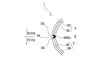
こうして製造されたおむつ1の主たる特長部分の1つとして、サイドシール部4が挙げられる。図7(c)に示す如き、サイドシール部4の延びる方向(図1中符号Xで示す方向。図4に示すおむつ1の縦方向Xと同方向。)と直交する方向(図4に示すおむつ1の横方向Yと同方向)の断面視において、前記分断によって生じたサイドシール部4の外縁4aが、外装体3の内方に向かって凸の弧状をなし、且つ外縁4aを含んでそれよりも外装体3の内方に、該外装体3を構成する4枚のシート35,36どうしの融着部40が形成され、該融着部40は、該外装体3の厚み方向(図7(c)の上下方向)の中央部が両端部(上端部及び下端部)に比して幅が広い。即ち、融着部40は、おむつ1の横方向Y(レーザー光による分断方向と直交する方向)に沿う断面視において、厚み方向において中央部に向けて融着部40の幅が徐々に広くなっており、所謂、三日月状又は半月状に形成されている〔図7(c)に示す融着部40は三日月状〕。
The
サイドシール部4は、シートの形成材料が溶融固化してなる融着部40の存在により、おむつ1の他の部位に比して硬くて肌触りが悪く、おむつ1の着用感を低下させる原因となり得る部位であるところ、このように融着部40がおむつ1の幅方向の断面視において三日月状又は半月状に形成されていると、従来のサイドシール部における融着部(例えば特許文献1の図1に記載の符号10で示す部位)のように同断面視において矩形形状に形成されている場合に比して、サイドシール部4を構成する外装体3の側縁部の角部3Sに存する融着部40の割合が減少し、これにより角部3Sが本来有する柔軟性、肌触り感が損なわれ難くなるため、従来品に比しておむつの着用感が向上する。一方、サイドシール部4の融着強度に大きな影響を及ぼす部位である、外装体3の側縁部の厚み方向の中央部(外装体3の一面側の角部3Sと他面側の3Sとに挟まれた部分)には、十分な量の融着部40が存しているため、サイドシール部4は実用上十分な融着強度を有し、おむつ1の着用中にサイドシール4が破れる等の不都合が生じ難い。
The
また、特に、サイドシール部4の外縁4aが外装体3の内方に向かって凸の弧状をなしていることにより、図8に示す如き、おむつ1の着用時にウエスト開口部8が拡げられた状態においては、腹側部1A側の外装体3の側縁部の角部3Sと背側部1B側の外装体3の側縁部の角部3Sとが接近し、両角部3S,3S間の離間距離が縮まるため、両角部3S,3S間に位置する融着部40は、該融着部40よりもおむつ1の外方側に位置する、互いに近接した両角部3S,3Sによって、手で触れ難く且つ外部から視認し難い状態となり、それによって、おむつ1の着用感のみならず外観も向上する。
In particular, the
このように、サイドシール部4の融着部40がおむつ1の幅方向の断面視において三日月状又は半月状に形成される理由は、図7(b)及び図7(c)に示すように、おむつ連続体10の分断予定部分10Cへのレーザー光30の照射中及び照射直後に、不織布からなるおむつ連続体10〔分断予定部分10C(サイドシール部4の形成予定部位)〕が、金属材料からなる支持部材21と押さえ部材24との間に介在配置されているためと推察される。即ち、おむつ連続体10(外層シート35及び内層シート36)を上下から挟持する支持部材21及び押さえ部材24の主たる形成材料である金属材料の方が、シート35,36の主たる形成材料である不織布に比して熱伝導率が高いため、レーザー光30の照射によってシート35,36に発生した熱は、該シート35,36に接する支持部材21又は押さえ部材24に速やかに吸収されやすいところ、レーザー光30の照射によっておむつ連続体10が分断されて形成された、サイドシール部4を構成する外装体3の側縁部の角部3Sは、該角部3Sに比して熱伝導率の高い支持部材21又は押さえ部材24に接しているため、該角部3Sに発生した熱は両部材21,24に速やかに吸収され、結果として、該角部3Sは、融着部40が形成される程の高温にはなり難く、そのため、融着部40の割合が極めて少ない部位となる。一方、外装体3の側縁部の厚み方向の中央部(外装体3の一面側の角部3Sと他面側の3Sとに挟まれた部分)は、熱伝導率の高い両部材21,24と接していないため、レーザー光30の照射によって該中央部に発生した熱は該中央部に留まって該中央部を溶融させ、結果として、該中央部に融着部40が多く偏在するようになる。
Thus, the reason why the fused
従って、融着部40をおむつ1の幅方向の断面視において三日月状又は半月状に形成し、前述した作用効果を奏させるようにするためには、支持部材21及び押さえ部材24は、鉄、アルミニウム、ステンレス鋼、銅等の金属材料やセラミックスからなり、且つ外装体3を構成する複数枚のシートの少なくとも一部(特におむつ1の外面を形成する外層シート35)は、その一部に樹脂材を含むものであり、具体的には例えば、不織布からなることが好ましい。また、複数枚のシート35の全てのシートに樹脂材が含まれることが好ましい。不織布としては、当該技術分野において通常用いられているものを特に制限無く用いることができる。
Therefore, in order to form the fused
レーザー光について説明すると、おむつ連続体10(帯状の外装体3)に照射するレーザー光としては、外装体3を構成するシート(外層シート35及び内層シート36)に吸収され該シートを発熱させる波長のレーザー光を用いる。ここで、「外装体を構成するシート」は、外装体の一方の面(支持部材21との当接面)を構成するシート(例えば前述した態様では外層シート35)に限定されず、外装体を構成するシートであればどれであっても良い。外装体に照射するレーザー光が、該外装体を構成する個々のシートについて、該シートに吸収されて該シートを発熱させる波長であるか否かは、シートの材質と、使用するレーザー光の波長との関係で決まる。外装体を構成するシートが、使い捨ておむつや生理用ナプキン等の吸収性物品(サニタリー用品)の製造に汎用される合成樹脂製の不織布やフィルムである場合、レーザー光としては、CO2レーザー、YAGレーザー、LDレーザー(半導体レーザー)、YVO4レーザー、ファイバーレーザー等を用いることが好ましい。また、外装体を構成するシートが、合成樹脂として、ポリエチレン、ポリエチレンテレフタレート、ポリプロピレン等を含む場合、該シートに吸収され該シートを良好に発熱させ得る波長としては、例えば、8.0μm以上15.0μm以下を用いることが好ましく、高出力のレーザー装置が存在するCO2レーザーの発振波長の9.0μm以上11.0μm以下を用いることが特に好ましい。レーザー光のスポット径、レーザー出力等は、外装体を構成するシートの材質や厚み等を考慮して適宜選択することができる。
Explaining the laser beam, the wavelength of the laser beam irradiated to the diaper continuous body 10 (band-shaped outer package 3) is absorbed by the sheets (
[サイドシール部視認性向上手段]
前述した、レーザー式接合装置を用いた製造方法の製造目的物であるおむつ1、即ち、外装体3の分断と溶着とが同時に実施される工程を経て得られた一対のサイドシール部4,4を具備するおむつ1は、サイドシール部4の柔軟性、肌触りに優れ、着用感が良好である。その一方、図2及び図8の記載等からもわかるように、少なくとも着用時においてサイドシール部4が、おむつ1の外面及び内面の何れにおいても、該サイドシール部4の周辺部よりも外方に突出しておらず、おむつ1の外面及び内面の状態がサイドシール部4を跨いで実質的に変化しないので、サイドシール部4を外部から視認し難く、サイドシール部4の目視による視認性が低い。
[Means for improving visibility of side seal part]
A pair of
そして、サイドシール部4の目視による視認性が低いと、例えばおむつ1の使用後に、着用者である乳幼児からその保護者(例えば母親)がおむつ1を取り外す際にサイドシール部4を見つけ難く、おむつ1の取り外し作業に手間取るおそれがある。そこで、本発明では、サイドシール部4の視認性を高める目的で、おむつ1にサイドシール部視認性向上手段を具備させている。サイドシール部視認性向上手段は、後述する第1、第2及び第3実施態様のように、好ましくは、サイドシール部4の近傍で且つウエスト開口部8の開口端部又はその近傍に位置している。また、サイドシール部視認性向上手段は、前述した、本体固定工程、重合加圧工程及びサイドシール部形成工程を有するパンツ型使い捨ておむつの製造方法において、該本体固定工程の終了後から該サイドシール部形成工程の終了前までに、外装体3に付与される。以下、この本発明に係るサイドシール部視認性向上手段並びにそれを具備する本発明のパンツ型使い捨ておむつ及びその製造方法について、その好ましい実施態様に基づき図面を参照して説明する。尚、後述する実施態様については、前記[基本技術]と異なる構成部分を主として説明し、同様の構成部分は同一の符号を付して説明を省略する。特に説明しない構成部分は、前記[基本技術]についての説明が適宜適用される。
And when the visibility of the
図9には、本発明のパンツ型使い捨ておむつの第1実施態様(パンツ型使い捨ておむつ50A)の要部である接合部51及び突出部52(サイドシール部視認性向上手段)並びにそれらの近傍が示されている。第1実施態様のおむつ50Aは、前述したおむつ1に、サイドシール部視認性向上手段としての突出部52とそれを形成するのに必要な接合部51とを具備させた点以外は、おむつ1と同様に構成されている。突出部52は、一対のサイドシール部4,4それぞれにおける、ウエスト開口部8の開口端部を形成する部分に位置し、図2に示すおむつ1において、点線の円で囲んだ部分に形成されている。
FIG. 9 shows a joint 51 and a protrusion 52 (side seal part visibility improving means) that are the main parts of the first embodiment of the pant-type disposable diaper of the present invention (pants-type
第1実施態様のおむつ50Aについて更に説明すると、おむつ50Aにおいては、図9に示すように、サイドシール部4の近傍で且つウエスト開口部8の開口端部81又はその近傍に、前身頃F(腹側部1A)における外装体3(外層シート35及び内層シート36)及び後身頃R(背側部1B)における外装体3(外層シート35及び内層シート36)を厚み方向に接合する接合部51が形成されていると共に(図9(a)参照)、サイドシール部4における開口端部81を形成する部分(より具体的には該部分の外装体3)が、おむつ50Aの着用時においてその周辺部よりも外方に突出して突出部52を形成しており(図9(b)参照)、この突出部52がサイドシール部視認性向上手段として機能する。即ち、おむつ50Aにおいては、突出部52の存在により、サイドシール部4の目視による視認性が向上している。
The
接合部51は、サイドシール部4を挟んで両側(前身頃F側及び後身頃R側)にそれぞれ1つずつ対称的に形成されている。接合部51は、前記サイドシール部形成工程において、加圧状態にある外装体3のサイドシール部4の形成予定部位を分断するためのレーザー光の照射に前後して、同じレーザー光を用いて外装体3に形成されるもので、レーザー光を照射する際の外装体3(おむつ連続体10)の前記加圧状態においては、円形状等、所定の平面視形状を有し、また、おむつ50A(前身頃Fにおける外装体3及び後身頃Rそれぞれにおける外装体3)を厚み方向に貫通する貫通孔を含んで構成されている場合もある。接合部51は、おむつ1の自然状態あるいは通常の使用状態においては、該接合部51が形成されている部位の収縮等により、目視では視認困難な状態となっている(図9(a)では説明容易の観点から接合部51を図示しているが、実際にこのように目視で視認できるとは限らない)。接合部51は、主として、突出部52を形成するために形成されるもので、接合部51自体は、サイドシール部視認性向上手段としては機能しなくても良く、また、接合部51の形状又は大きさを適宜調整して接合部51を目視により視認可能にさせることで突出部52をより目立たさせ、サイドシール部4の目視による視認性を向上させても良い。
One joining
第1実施態様のおむつ50Aの製造方法においては、外装体3の分断及び接合部51の形成を、外装体3を構成するシート(外層シート35及び内層シート36)に吸収され該シートを発熱させる波長のレーザー光を該外装体3に照射することにより実施する。より具体的には、図6(a)に示すように、レーザー式接合装置20における支持部材21の所定箇所(スリット状の開口部27の近傍)に、レーザー光30が通過可能な接合部形成用光透過部27Aを予め穿設しておき、前記加圧状態の外装体3(おむつ連続体10)に対し、支持部材21側からスリット状の開口部27を介してレーザー光30を照射する前又は照射した後に、支持部材21側から接合部形成用光透過部27Aを介してレーザー光30を照射する。これにより、外装体3における、光透過部27Aに対応する部分に存するシート35,36の形成材料(繊維等)が、レーザー光30の直射による発熱によって溶融、又は気化して消失する。レーザー光30の直射による発熱によってシート35,36の形成材料が消失せずに溶融した場合には、その溶融部分が接合部51となり、前記加圧状態下において該接合部51にて前身頃Fにおける外装体3と後身頃Rにおける外装体3とが接合される。また、レーザー光30の直射による発熱によってシート35,36の形成材料が気化して消失した場合には、その消失部分が、前身頃Fにおける外装体3及び後身頃Rにおける外装体3を厚み方向に貫通する貫通孔となると共に、該貫通孔の開孔縁部に存する該形成材料がレーザー光30によって間接的に熱せられて溶融し、その溶融部分(該貫通孔の開口縁部)が接合部51となり、前記加圧状態下において該接合部51にて前身頃Fにおける外装体3と後身頃Rにおける外装体3とが接合される。尚、光透過部27Aの平面視形状は、図6に示す如き、円形状に制限されず、例えば矩形状等、種々の形状に設定可能である。
In the manufacturing method of the
こうして、おむつ50Aにおける、サイドシール部4の近傍で且つウエスト開口部8の開口端部81又はその近傍に接合部51が形成され、該接合部51にて前身頃Fにおける外装体3と後身頃Rにおける外装体3とが接合されると、外装体3(外層シート35、内層シート36)における、接合部51の外方(サイドシール部4側)に位置する部分が、おむつ1の着用時において、環状に形成されるウエスト開口部8から外方に突出し、突出部52が形成される。要するに、おむつ50Aの着用時において、突出部52は、着用者の身体に沿っていないため、目視により視認できる。従って、おむつ50Aのサイドシール部4が目視による視認性が低いものであっても、おむつ50Aの着用時においては、その近傍に位置する突出部52の存在によって、着用状態のおむつ50Aを着用者の身体から取り外す際には、サイドシール部4を速やかに確認することができ、その後は常法通り、サイドシール部4においておむつ50Aを前身頃Fと後身頃Rとに引き裂くことができ、使用後のおむつを速やかに身体から取り外すことができる。
Thus, the joint 51 is formed in the
突出部52(サイドシール部視認性向上手段)をより確実に形成する観点から、接合部51とサイドシール部4との離間距離は、好ましくは2mm以上、更に好ましくは3mm以上、そして、好ましくは20mm以下、更に好ましくは15mm以下、より具体的には、好ましくは2mm以上20mm以下、更に好ましくは3mm以上15mm以下である。また、同様の観点から、接合部51と直上に位置するウエスト開口部8の開口端部81の端縁82との離間距離は、好ましくは1mm以上、更に好ましくは3mm以上、そして、好ましくは20mm以下、更に好ましくは15mm以下、より具体的には、好ましくは1mm以上20mm以下、更に好ましくは3mm以上15mm以下である。尚、ここでいう「離間距離」は、展開且つ伸長状態のおむつについて測定したものであり、「展開且つ伸長状態」については、前述した通りである。
From the viewpoint of more reliably forming the protruding portion 52 (side seal portion visibility improving means), the separation distance between the
尚、本発明においては、前記サイドシール部形成工程における外装体の分断及び接合部の形成は、熱源を用いて該外装体を溶融することにより実施し、該接合部の形成によりおむつの着用時における突出部の形成を可能にすれば良く、熱源を用いた外装体の溶融は、前述の如き、外装体へのレーザー光の照射に制限されず、それ以外の他の方法、例えば、公知のヒートロール装置等を用いた外装体の加熱圧着、あるいは公知の超音波振動装置等を用いた外装体への超音波振動の付与、等により実施することもできる。 In the present invention, the outer body is divided and the joint is formed in the side seal portion forming step by melting the outer body using a heat source, and when the diaper is worn by forming the joint. It is only necessary to allow the protrusions to be formed in the case, and the melting of the exterior body using the heat source is not limited to the irradiation of the laser beam to the exterior body as described above. It can also be carried out by thermocompression bonding of the exterior body using a heat roll device or the like, or applying ultrasonic vibration to the exterior body using a known ultrasonic vibration device or the like.
図10には、本発明のパンツ型使い捨ておむつの第2実施態様(パンツ型使い捨ておむつ50B)が示されている。第2実施態様のおむつ50Bは、前述したおむつ1に、サイドシール部視認性向上手段としての段差53を具備させた点以外は、おむつ1と同様に構成されている。
The 2nd embodiment (underpants type
第2実施態様のおむつ50Bについて更に説明すると、おむつ50Bにおいては、図10に示すように、ウエスト開口部8の開口端部を形成する、前身頃Fにおける外装体3の端縁82Fと後身頃Rにおける外装体3の端縁82Rとは、おむつ1の上下方向(図10の上下方向)において同位置になくズレており、サイドシール部4の上方に、そのズレに起因する両端縁82F,82R間の段差53が生じており、この段差53がサイドシール部視認性向上手段として機能する。即ち、おむつ50Bにおいては、段差53の存在により、サイドシール部4の目視による視認性が向上している。尚、おむつ50Bにおいては、後身頃Rの端縁82Rが前身頃Fの端縁82Fよりも上方に位置しているが、これとは逆に、前身頃Fの端縁82Fが後身頃Rの端縁82Rよりも上方に位置していても良い。
The
第2実施態様のおむつ50Bの製造方法においては、前述したおむつ連続体10(帯状の外装体3)の製造において、前記サイドシール部形成工程の前に、サイドシール部視認性向上手段(段差53)を形成する。詳細には、前記重合加圧工程において外装体3の前身頃側と後身頃側とを重ね合わせるとき、即ち、図11(a)又は図11(b)に示すように、帯状の外装体3をその幅方向に折り畳むときに、該外装体3の長手方向(図11の左右方向)に沿う両端縁82F,82Rどうしを一致させずに意図的にずらすことにより、図11(c)に示すように段差53を形成する。このずらし量(一方の端縁と他方の端縁との離間距離)が、段差53の高さt(図10参照)に相当する。段差53を形成する際における、「外装体の長手方向に沿う両端縁どうしの意図的なずらし」の方法としては、例えば、図11(a)に示す下記方法a、及び図11(b)に示す下記方法bが挙げられ、何れを用いても構わない。
In the manufacturing method of the
・方法a:おむつを縦方向Xに二分する仮想中心線CLを境にして、前身頃Fと後身頃Rとで縦方向Xの長さが等しい場合に、仮想中心線CLを折曲線とせずに、仮想中心線CLと平行な別の直線を折曲線Qとする方法(図11(a)参照)。図11(a)に示す実施態様では、図10に示す如く後身頃Rの端縁82Rを前身頃Fの端縁82Fよりも上方に位置させる観点から、折曲線Qは、仮想中心線CLよりも前身頃F(腹側部1A)側にずれている。即ち、図11(a)に示す実施態様(おむつ50Bを縦方向に二分する仮想中心線CLを境にして、前身頃Fと後身頃Rとで縦方向Xの長さが等しい場合)では、帯状の外装体3(おむつ連続体10)の長手方向に沿う両端縁82F,82Rどうしの意図的なずらしは、仮想中心線CLと平行な別の直線を折曲線として、帯状の該外装体3を該折曲線にて折り畳むことによってなされる。
Method a: When the length in the vertical direction X is equal between the front body F and the back body R with respect to the virtual center line CL that bisects the diaper in the vertical direction X, the virtual center line CL is not folded. In addition, another straight line parallel to the virtual center line CL is used as a folding line Q (see FIG. 11A). In the embodiment shown in FIG. 11 (a), from the viewpoint of positioning the
・方法b:腹側部1Aと背側部1Bとで縦方向Xの長さを異ならせておき、股下部1Cを縦方向Xに二分する仮想中心線CL’を折曲線とする方法(図11(b)参照)。即ち、図11(b)に示す実施態様では、帯状の外装体3(おむつ連続体10)の長手方向に沿う両端縁82F,82Rどうしの意図的なずらしは、おむつ50Bにおいて腹側部1Aと背側部1Bとで縦方向Xの長さを異ならせておき、おむつ50Bの股下部1Cを縦方向Xに二分する仮想中心線CL’を折曲線として、帯状の該外装体3を該折曲線(仮想中心線CL’)にて折り畳むことによってなされる。図11(b)に示す実施態様では、図10に示す如く後身頃Rの端縁82Rを前身頃Fの端縁82Fよりも上方に位置させる観点から、腹側部1Aは背側部1Bよりも縦方向Xの長さが短くなっている。また、股下部1Cを縦方向Xに二分する仮想中心線CL’は、おむつ1を縦方向Xに二分する仮想中心線に一致している。
Method b: A method in which the length in the longitudinal direction X is different between the
段差53の高さは、サイドシール部4の目視による視認性の向上とおむつ1としての形状維持とのバランスの観点から、好ましくは2mm以上、更に好ましくは3mm以上、そして、好ましくは20mm以下、更に好ましくは15mm以下、より具体的には、好ましくは2mm以上20mm以下、更に好ましくは3mm以上15mm以下である。尚、ここでいう「段差の高さ」は、自然状態のおむつについて測定したものである。
The height of the
図12には、本発明のパンツ型使い捨ておむつの第3実施態様(パンツ型使い捨ておむつ50C)要部であるマーク54(サイドシール部視認性向上手段)及びその近傍が示されている。第3実施態様のおむつ50Cは、前述したおむつ1に、サイドシール部視認性向上手段としてのマーク54を具備させた点以外は、おむつ1と同様に構成されている。
FIG. 12 shows a mark 54 (side seal portion visibility improving means) which is a main part of the third embodiment of the pant-type disposable diaper of the present invention (pants-type
第3実施態様のおむつ50Cについて更に説明すると、おむつ50Cにおいては、図12に示すように、前身頃F(腹側部1A)における外装体3の外面(非肌当接面)で且つサイドシール部4の近傍、又は後身頃R(背側部1B)における外装体3の外面(非肌当接面)で且つサイドシール部4の近傍に、目視により認識可能なマーク54が形成されており、このマーク54がサイドシール部視認性向上手段として機能する。即ち、おむつ50Cにおいては、マーク54の存在により、サイドシール部4の目視による視認性が向上している。
The
マーク54は、図12に示すように、サイドシール部4の近傍で且つウエスト開口部8の開口端部81又はその近傍に、サイドシール部4を挟んで両側(前身頃F側及び後身頃R側)にそれぞれ1つずつ対称的に形成されており、平面視においてハート型を有している。マーク54によるサイドシール部4の目視による視認性をより確実に向上させる観点から、マーク54とサイドシール部4との離間距離は、好ましくは1mm以上、更に好ましくは5mm以上、そして、好ましくは30mm以下、更に好ましくは25mm以下、より具体的には、好ましくは1mm以上30mm以下、更に好ましくは5mm以上25mm以下である。また、同様の観点から、マーク54と直上に位置するウエスト開口部8の開口端部81の端縁82との離間距離は、好ましくは1mm以上、更に好ましくは5mm以上、そして、好ましくは60mm以下、更に好ましくは50mm以下、より具体的には、好ましくは1mm以上60mm以下、更に好ましくは5mm以上50mm以下である。尚、ここでいう「離間距離」は、展開且つ伸長状態のおむつについて測定したものであり、「展開且つ伸長状態」については、前述した通りである。
As shown in FIG. 12, the
第3実施態様のおむつ50Cの製造方法においては、前述したおむつ連続体10(帯状の外装体3)の製造において、前記サイドシール部形成工程の前に、サイドシール部視認性向上手段(マーク54)を形成する。詳細には、前記重合加圧工程において外装体3の前身頃側と後身頃側とを重ね合わせる前、即ち、帯状の外装体3をその幅方向に折り畳む前に、該外装体3の所定箇所にエンボス加工又は印刷によりマーク54を形成する。エンボス加工方法及び印刷方法は特に制限されず、それぞれ公知の方法を適宜選択できる。
In the manufacturing method of the
おむつ50Cにおいては、外装体3として、図13に示す複合伸縮部材3Aを用いており、図14に示すように、この複合伸縮部材3Aの製造で利用するエンボス加工においてマーク54を形成している。複合伸縮部材3Aは下記構成1〜構成3を具備している。複合伸縮部材3Aとしては、例えば、本出願人の先の出願に係る特開2009−118986号公報に記載の複合伸縮部材を適用することができる。尚、下記構成1〜構成3の複合伸縮部材3Aは、第1実施態様及び第2実施態様の外装体3としても制限無く用いることができる。
In the
・構成1:外層シート35及び内層シート36は、複合伸縮部材3Aの伸縮方向(横方向Y)及びそれに直交する方向(縦方向X)において間欠的な複数の接合部37により互いに接合されている。
・構成2:複数本の弾性部材5,6それぞれは、接合部37を通らないように配されると共に、弾性部材5,6の長さ方向の両端部(サイドシール部4付近等)を除いた部分において外層シート35及び内層シート36に固定されていない。
・構成3:外層シート35及び内層シート36それぞれは、複合伸縮部材3Aの自然状態において各々複数本の弾性部材5,6に亘って連続して延びる複数本の襞38を形成している。
Configuration 1: The
Configuration 2: Each of the plurality of
Configuration 3: Each of the
図14には、複合伸縮部材3Aの製造においてマーク54を形成する工程が示されている。このマーク形成工程(複合伸縮部材の製造工程)は、図5に示すおむつ連続体10の製造工程において、一対のニップロール11,11よりも搬送方向の下流側で且つ吸収性本体2の配置前に実施される。より具体的には、図14に示すように、一対のニップロール11,11よりも搬送方向の下流側に配置されたエンボスロール12とこれを受けるアンビルロール13とを用い、両ロール12,13間に帯状の外装体3を導入し、該外装体3に接合部37を形成すると共に、そのサイドシール部4の形成予定部分(分断予定部分)10Cの近傍にマーク54を形成する。帯状の外装体3は、該外装体3を構成する外層シート35がエンボスロール12と接するように、両ロール12,13間に導入される。帯状の外装体3(内層シート36)と接触するアンビルロール13の周面は平滑であるのに対し、帯状の外装体3(外層シート35)と接触するエンボスロール12の周面には、複合伸縮部材3Aの接合部37に対応して、多数のエンボスピン14が設けられていると共に、マーク54に対応して、マーク54の平面視形状(ハート型)と同形状の先端部を有するマーク形成用ピン15が設けられており、これらのピン14,15の先端部で外装体3を外層シート35側から押圧することにより、接合部37及びマーク54が形成される。両ピン14,15は、ヒートエンボスピンでも良く、超音波エンボスピンでも良い。このように、両ロール12,13間に帯状の外装体3を導入することにより、マーク54が形成された複合伸縮部材3Aからなる帯状の外装体3が得られる。尚、おむつ50Cの着用時において吸収性本体2に皴が発生する等の不都合を防止する観点から、弾性部材6,7における吸収性本体2と重なる部分には、該弾性部材6,7を細かく分断する等してその伸縮性の発現が抑制された、非伸縮部を形成することができる。この弾性部材6,7の非伸縮部は、両ロール12,13を用いて接合部37及びマーク54の形成と同時に形成しても良く、あるいはこれらの形成後に、両ロール12,13とは別体の切断ロール(図示せず)を用いて形成しても良い。前者の場合、エンボスロール12の周面には、弾性部材6,7の非伸縮部形成手段としての凸部、カッター刃等を形成しておく。
FIG. 14 shows a process of forming the
尚、本発明に係るサイドシール部視認性向上手段としてのマークは、図12に示す如きハート型に限定されず、その平面視形状は特に制限されず、図形、記号、文字、絵柄、あるいはこれらの組み合わせ等から構成することができる。例えば、図15(a)に示すように、おむつの使用後に着用者の身体から取り外す際に引き裂かれる箇所であるサイドシール部4の位置を明確にすべく、記号(矢印)からなるマーク54Aを、サイドシール部4を挟んで両側に形成することができる。また、本発明に係るマークは、図15(b)に示す記号からなるマーク54Aのように、サイドシール部4の全長に沿って複数形成しても良い。本発明に係るマークの他の具体例として、図15(c)には、文字からなるマーク54Bが示されており、また図15(d)には、記号(矢印)からなるマーク54Aと文字からなるマーク54Bとの組み合わせが示されている。
The mark as the side seal portion visibility improving means according to the present invention is not limited to the heart shape as shown in FIG. 12, and the shape in plan view is not particularly limited, and may be a figure, a symbol, a character, a pattern, or these It can comprise from the combination of these. For example, as shown in FIG. 15 (a), in order to clarify the position of the
以上、本発明をその実施態様に基づいて説明したが、本発明は、前記実施態様に制限されることなく、本発明の趣旨を逸脱しない範囲で適宜変更が可能である。例えば、シート積層体は、図6(a)に示す如き4枚のシートが重ねられたものの他、2枚、3枚又は5枚以上のシートが重ねられたものであっても良い。また、おむつ連続体10を円筒ロール23(支持部材21)に皴やたるみを発生させずに巻き掛けるために、レーザー式接合装置20に、おむつ連続体10のテンションを制御する機構を具備させても良い。また、レーザー光の照射によって発生したガスを開口部27から除去するために、レーザー式接合装置20に、該ガスの排気手段又は開口部27にエアーを吹き付ける手段を具備させても良い。また、レーザー式接合装置20は、押さえ部材24におけるおむつ連続体10との当接面に付着した樹脂等を除去するための機構を備えていても良い。
As mentioned above, although this invention was demonstrated based on the embodiment, this invention is not restrict | limited to the said embodiment, In the range which does not deviate from the meaning of this invention, it can change suitably. For example, the sheet laminated body may be one in which two sheets, three sheets, or five or more sheets are stacked in addition to those in which four sheets are stacked as shown in FIG. Moreover, in order to wind the diaper
また、前記実施形態における外装体3は、図4に示すように、腹側部1Aと背側部1Bとで分割されずに、腹側部1A、股下部1C及び背側部1Bに亘る砂時計状等の連続した形状を有していたが、本発明における外装体は、このような連続した形状に制限されず、例えば、着用者の腹側(前側)に配される腹側シート部材と、着用者の背側(後側)に配される背側シート部材とに分割されており、吸収性本体がこれら両シート部材に架け渡して固定されていても良い。このような分割タイプの外装体を具備するパンツ型使い捨ておむつの製造方法における前記重合加圧工程は、吸収性本体が固定された帯状の外装体の前身頃側(帯状の腹側シート部材)と後身頃側(帯状の背側シート部材)とを重ね合わせ、重ね合わされた該外装体(両シート部材)におけるサイドシール部の形成予定部位を加圧状態にする。
In addition, as shown in FIG. 4, the
また、前記実施態様では、前記重合加圧工程の実施前に、図5に示すように、帯状の外装体3の搬送方向に沿う両側部3a,3a、即ち、帯状の外層シート35及び帯状の内層シート36それぞれの搬送方向に沿う両側部を、吸収性本体2の長手方向両端部を覆うように折り返していたが、帯状の外層シート35として、帯状の内層シート36よりも幅方向(長手方向と直交する方向)の長さが長いものを用い、両シート35,36を重ね合わせたときに内層シート36の側縁から外方に延出する、外層シート35の延出部のみを、吸収性本体2の長手方向両端部を覆うように折り返しても良い。その場合、おむつ連続体10の分断予定部分10Cは、ウエスト開口部8の開口端部及びその近傍が、6枚のシートが重ねられた6層構造部分、それ以外の部分が、4枚のシートが重ねられた4層構造部分となる。また、帯状の外装体3の搬送方向に沿う両側部3a,3a、即ち、帯状の外層シート35及び帯状の内層シート36それぞれの搬送方向に沿う両側部は、折り畳まなくても良い。
Moreover, in the said embodiment, before implementation of the said superposition | polymerization pressurization process, as shown in FIG. 5, both
また、前記第1実施態様〜第3実施態様のサイドシール部視認性向上手段を、組み合わせてパンツ型使い捨ておむつに具備させても良い。前述した一の実施態様のみが有する部分は、すべて適宜相互に利用できる。 Moreover, you may comprise in a pants type disposable diaper combining the side seal part visibility improvement means of the said 1st embodiment-the 3rd embodiment. All the parts of only one embodiment described above can be used as appropriate.
前述した本発明の実施態様に関し、更に以下の付記(パンツ型使い捨ておむつ、パンツ型使い捨ておむつの製造方法)を開示する。 In addition to the above-described embodiment of the present invention, the following additional notes (pants-type disposable diapers and methods for producing pants-type disposable diapers) are disclosed.
<1>
吸収性本体と、該吸収性本体の非肌当接面側に配されて該吸収性本体を固定している外装体とを備え、且つ前身頃における該外装体の左右両側縁部と後身頃における該外装体の左右両側縁部とが接合されて一対のサイドシール部、ウエスト開口部及び一対のレッグ開口部が形成されているパンツ型使い捨ておむつであって、
前記サイドシール部は、前記おむつの着用時において目視による視認性が低く、該サイドシール部の目視による視認性を高め得るサイドシール部視認性向上手段を該サイドシール部の近傍に具備しているパンツ型使い捨ておむつ。
<1>
An absorbent body, and an exterior body disposed on the non-skin contact surface side of the absorbent body and fixing the absorbent body, and both left and right edges of the exterior body and the back body in the front body A pants-type disposable diaper in which a pair of side seal parts, a waist opening part and a pair of leg opening parts are formed by joining right and left side edges of the exterior body in
The side seal portion is provided with a side seal portion visibility improving means in the vicinity of the side seal portion, which has low visibility when worn on the diaper and can enhance the visibility of the side seal portion. Pants-type disposable diaper.
<2>
前記サイドシール部は、前記おむつの自然状態において目視による視認性が低い前記<1>に記載のパンツ型使い捨ておむつ。
<3>
前記サイドシール部視認性向上手段は、前記ウエスト開口部の開口端部又はその近傍に位置している前記<1>又は<2>に記載のパンツ型使い捨ておむつ。
<2>
The said side seal part is the underpants type disposable diaper as described in said <1> with low visibility by visual observation in the natural state of the said diaper.
<3>
The said side seal part visibility improvement means is the underpants type disposable diaper as described in said <1> or <2> located in the opening edge part of the said waist opening part, or its vicinity.
<4>
前記サイドシール部の近傍で且つ前記ウエスト開口部の開口端部又はその近傍に、前記前身頃における前記外装体及び前記後身頃における該外装体を厚み方向に接合する接合部が形成されていると共に、該サイドシール部における該ウエスト開口部の開口端部を形成する部分が、前記おむつの着用時においてその周辺部よりも外方に突出して突出部を形成しており、該突出部が前記サイドシール部視認性向上手段として機能する前記<1>〜<3>のいずれか1に記載のパンツ型使い捨ておむつ。
<5>
前記接合部と前記サイドシール部との離間距離は、好ましくは2mm以上、更に好ましくは3mm以上、そして、好ましくは20mm以下、更に好ましくは15mm以下、より具体的には、好ましくは2mm以上20mm以下、更に好ましくは3mm以上15mm以下であり、
前記接合部と前記ウエスト開口部の開口端部の端縁との離間距離は、好ましくは1mm以上、更に好ましくは3mm以上、そして、好ましくは20mm以下、更に好ましくは15mm以下、より具体的には、好ましくは1mm以上20mm以下、更に好ましくは3mm以上15mm以下である前記<4>に記載のパンツ型使い捨ておむつ。
<4>
In the vicinity of the side seal portion and at the opening end of the waist opening or in the vicinity thereof, a joining portion for joining the exterior body in the front body and the exterior body in the back body in the thickness direction is formed. The portion of the side seal portion that forms the opening end of the waist opening protrudes outward from the peripheral portion when the diaper is worn to form a protrusion, and the protrusion is the side The underpants-type disposable diaper according to any one of <1> to <3>, which functions as a seal portion visibility improving unit.
<5>
The separation distance between the joint portion and the side seal portion is preferably 2 mm or more, more preferably 3 mm or more, and preferably 20 mm or less, more preferably 15 mm or less, more specifically preferably 2 mm or more and 20 mm or less. More preferably, it is 3 mm or more and 15 mm or less,
The separation distance between the joint and the edge of the opening end of the waist opening is preferably 1 mm or more, more preferably 3 mm or more, and preferably 20 mm or less, more preferably 15 mm or less, more specifically. The pants-type disposable diaper according to <4>, preferably 1 mm or more and 20 mm or less, more preferably 3 mm or more and 15 mm or less.
<6>
前記ウエスト開口部の開口端部を形成する、前記前身頃における前記外装体の端縁と前記後身頃における該外装体の端縁とは、前記おむつの上下方向においてズレており、前記サイドシール部の上方に、そのズレに起因する両端縁間の段差が生じており、該段差が前記サイドシール部視認性向上手段として機能する前記<1>〜<5>のいずれか1に記載のパンツ型使い捨ておむつ。
<7>
前記後身頃の端縁が前記前身頃の端縁よりも上方に位置している前記<6>に記載のパンツ型使い捨ておむつ。
<8>
前記前身頃の端縁が前記後身頃の端縁よりも上方に位置している前記<6>に記載のパンツ型使い捨ておむつ。
<9>
前記段差は、好ましくは2mm以上、更に好ましくは3mm以上、そして、好ましくは20mm以下、更に好ましくは15mm以下、より具体的には、好ましくは2mm以上20mm以下、更に好ましくは3mm以上15mm以下である前記<6>〜<8>のいずれか1に記載のパンツ型使い捨ておむつ。
<6>
The edge of the exterior body in the front body and the edge of the exterior body in the back body forming the opening end of the waist opening are displaced in the vertical direction of the diaper, and the side seal portion The underpants type | mold of any one of said <1>-<5> in which the level | step difference between the both-ends edge resulting from the shift | offset | difference arises above this, and this level | step difference functions as said side seal part visibility improvement means Disposable diapers.
<7>
The pants-type disposable diaper according to <6>, wherein an edge of the back body is positioned above an edge of the front body.
<8>
The underpants-type disposable diaper according to <6>, wherein an edge of the front body is positioned above an edge of the back body.
<9>
The step is preferably 2 mm or more, more preferably 3 mm or more, and preferably 20 mm or less, more preferably 15 mm or less, more specifically, preferably 2 mm or more and 20 mm or less, more preferably 3 mm or more and 15 mm or less. The underpants-type disposable diaper according to any one of <6> to <8>.
<10>
前記前身頃における前記外装体の外面で且つ前記サイドシール部の近傍、又は前記後身頃における該外装体の外面で且つ該サイドシール部の近傍に、目視により認識可能なマークが形成されており、該マークが前記サイドシール部視認性向上手段として機能する前記<1>〜<9>のいずれか1に記載のパンツ型使い捨ておむつ。
<11>
前記マークは、前記サイドシール部を挟んで両側(前身頃側及び後身頃側)にそれぞれ1つずつ対称的に形成されている前記<10>に記載のパンツ型使い捨ておむつ。
<12>
前記マークと前記サイドシール部との離間距離は、好ましくは1mm以上、更に好ましくは5mm以上、そして、好ましくは30mm以下、更に好ましくは25mm以下、より具体的には、好ましくは1mm以上30mm以下、更に好ましくは5mm以上25mm以下である前記<10>又は<11>に記載のパンツ型使い捨ておむつ。
<13>
前記マークと直上に位置する前記ウエスト開口部の開口端部の端縁との離間距離は、好ましくは1mm以上、更に好ましくは5mm以上、そして、好ましくは60mm以下、更に好ましくは50mm以下、より具体的には、好ましくは1mm以上60mm以下、更に好ましくは5mm以上50mm以下である前記<10>〜<12>のいずれか1に記載のパンツ型使い捨ておむつ。
<14>
前記マークは、図形、記号、文字、絵柄、あるいはこれらの組み合わせである前記<10>〜<13>のいずれか1に記載のパンツ型使い捨ておむつ。
<15>
前記マークは、前記サイドシール部の全長に沿って複数形成されている前記<10>〜<14>のいずれか1に記載のパンツ型使い捨ておむつ。
<10>
On the outer surface of the outer body in the front body and in the vicinity of the side seal portion, or on the outer surface of the outer body in the rear body and in the vicinity of the side seal portion, a visually recognizable mark is formed, The underpants-type disposable diaper according to any one of <1> to <9>, wherein the mark functions as means for improving the visibility of the side seal part.
<11>
The pants-type disposable diaper according to <10>, wherein the mark is formed symmetrically on each of both sides (a front body side and a back body side) across the side seal portion.
<12>
The distance between the mark and the side seal portion is preferably 1 mm or more, more preferably 5 mm or more, and preferably 30 mm or less, more preferably 25 mm or less, more specifically preferably 1 mm or more and 30 mm or less, More preferably, the pants-type disposable diaper according to the above <10> or <11>, which is 5 mm or more and 25 mm or less.
<13>
The separation distance between the mark and the edge of the opening end of the waist opening located immediately above is preferably 1 mm or more, more preferably 5 mm or more, and preferably 60 mm or less, more preferably 50 mm or less, more specifically. Specifically, the pants-type disposable diaper according to any one of <10> to <12>, which is preferably 1 mm to 60 mm, more preferably 5 mm to 50 mm.
<14>
The pants-type disposable diaper according to any one of <10> to <13>, wherein the mark is a figure, a symbol, a character, a design, or a combination thereof.
<15>
The pants-type disposable diaper according to any one of <10> to <14>, wherein a plurality of the marks are formed along the entire length of the side seal portion.
<16>
前記サイドシール部の外縁が、前記外装体の内方に向かって凸の弧状をなし、且つ該外縁を含んでそれよりも該外装体の内方に、該外装体を構成する複数のシートどうしの融着部が形成されている前記<1>〜<14>のいずれか1に記載のパンツ型使い捨ておむつ。
<17>
前記融着部は、前記おむつの横方向に沿う断面視において、厚み方向において中央部に向けて該融着部の幅が徐々に広くなっている前記<16>に記載のパンツ型使い捨ておむつ。
<18>
前記融着部は、前記おむつの横方向に沿う断面視において、三日月状又は半月状に形成されている前記<16>又は<17>に記載のパンツ型使い捨ておむつ。
<19>
前記おむつの着用時に前記ウエスト開口部が拡げられた状態においては、腹側部側の前記外装体の側縁部の角部と背側部側の前記外装体の側縁部の角部とが接近し、両角部間の離間距離が縮まり、両角部間に位置する前記融着部は、該融着部よりも前記おむつの外方側に位置する、互いに近接した両角部によって、手で触れ難く且つ外部から視認し難い状態となっている前記<16>〜<18>のいずれか1に記載のパンツ型使い捨ておむつ。
<20>
前記外装体は、前記おむつの外面を形成する外層シートと、該外層シートの内面側に配され、おむつの内面を形成する内層シートと、両シート間に固定された複数本の糸状又は帯状の弾性部材とを含んで構成されている前記<1>〜<19>のいずれか1に記載のパンツ型使い捨ておむつ。
<21>
前記外装体は、樹脂材としてポリエチレン、ポリエチレンテレフタレート、ポリプロピレンの熱融着性の合成樹脂を含み、且つ不織布、フィルム又は不織布とフィルムとのラミネートシートからなり、該不織布は、エアースルー不織布、ヒートロール不織布、スパンレース不織布、スパンボンド不織布又はメルトブローン不織布である前記<1>〜<20>のいずれか1に記載のパンツ型使い捨ておむつ。
<22>
前記外装体として、複合伸縮部材を用いており、該複合伸縮部材は、前記おむつの外面を形成する外層シートと、該外層シートの内面側に配され、おむつの内面を形成する内層シートと、両シート間に固定された複数本の糸状又は帯状の弾性部材とを含んで構成され且つ下記構成1〜構成3を具備している前記<1>〜<21>のいずれか1に記載のパンツ型使い捨ておむつ。
・構成1:前記外層シート及び前記内層シートは、前記複合伸縮部材の伸縮方向及びそれに直交する方向において間欠的な複数の接合部により互いに接合されている。
・構成2:複数本の前記弾性部材それぞれは、前記接合部を通らないように配されると共に、該弾性部材の長さ方向の両端部を除いた部分において前記外層シート及び前記内層シートに固定されていない。
・構成3:前記外層シート及び前記内層シートそれぞれは、前記複合伸縮部材の自然状態において各々複数本の前記弾性部材に亘って連続して延びる複数本の襞を形成している。
<23>
前記外装体は、腹側部と背側部とで分割されておらず、腹側部、股下部及び背側部に亘る砂時計状等の連続した形状を有している前記<1>〜<22>のいずれか1に記載のパンツ型使い捨ておむつ。
<24>
前記外装体は、着用者の腹側(前側)に配される腹側シート部材と、着用者の背側(後側)に配される背側シート部材とに分割されており、前記吸収性本体がこれら両シート部材に架け渡して固定されている前記<1>〜<23>のいずれか1に記載のパンツ型使い捨ておむつ。
<16>
The outer edges of the side seal portions form a convex arc shape toward the inside of the exterior body, and the plurality of sheets constituting the exterior body are included inside the exterior body and including the outer edge. The pants-type disposable diaper according to any one of the above items <1> to <14>, in which a fused part is formed.
<17>
The pants-type disposable diaper according to <16>, wherein the fusion part has a width that gradually increases toward a central part in a thickness direction in a cross-sectional view along the lateral direction of the diaper.
<18>
The pants-type disposable diaper according to <16> or <17>, wherein the fusion part is formed in a crescent shape or a half moon shape in a cross-sectional view along a lateral direction of the diaper.
<19>
In a state where the waist opening is widened when the diaper is worn, a corner of the side edge of the exterior body on the ventral side and a corner of the side edge of the exterior body on the back side are The distance between the two corners is reduced, and the fused portion located between the two corners is touched by the two corners located closer to each other on the outer side of the diaper than the fused portion. The pants-type disposable diaper according to any one of the above items <16> to <18>, which is difficult and difficult to visually recognize from the outside.
<20>
The exterior body includes an outer layer sheet that forms an outer surface of the diaper, an inner layer sheet that is disposed on an inner surface side of the outer layer sheet and forms an inner surface of the diaper, and a plurality of thread-like or belt-like shapes fixed between the two sheets. The underpants-type disposable diaper according to any one of the above items <1> to <19>, comprising an elastic member.
<21>
The exterior body includes a heat-fusible synthetic resin of polyethylene, polyethylene terephthalate, and polypropylene as a resin material, and is composed of a nonwoven fabric, a film, or a laminate sheet of a nonwoven fabric and a film. The pants-type disposable diaper according to any one of <1> to <20>, which is a nonwoven fabric, a spunlace nonwoven fabric, a spunbond nonwoven fabric, or a meltblown nonwoven fabric.
<22>
A composite elastic member is used as the exterior body, and the composite elastic member is an outer layer sheet that forms the outer surface of the diaper, and an inner layer sheet that is disposed on the inner surface side of the outer layer sheet and forms the inner surface of the diaper. The pants according to any one of the above items <1> to <21>, comprising a plurality of thread-like or belt-like elastic members fixed between the two sheets and comprising the following
Configuration 1: The outer layer sheet and the inner layer sheet are joined to each other by a plurality of intermittent joining portions in the stretching direction of the composite stretchable member and the direction orthogonal thereto.
Configuration 2: Each of the plurality of elastic members is arranged so as not to pass through the joint portion, and is fixed to the outer layer sheet and the inner layer sheet in a portion excluding both end portions in the length direction of the elastic member. It has not been.
Configuration 3: Each of the outer layer sheet and the inner layer sheet forms a plurality of ridges that continuously extend over the plurality of elastic members in the natural state of the composite stretchable member.
<23>
The said exterior body is not divided | segmented into the ventral | abdominal part and the back | dorsal part, <1>-<which has continuous shapes, such as the hourglass shape over an abdominal part, a crotch part, and a dorsal part. The pants-type disposable diaper according to any one of 22>.
<24>
The said exterior body is divided | segmented into the abdominal sheet member distribute | arranged to a wearer's belly side (front side), and the back | dorsal sheet member distribute | arranged to a wearer's back side (rear side), The said absorptivity The underpants-type disposable diaper according to any one of the above <1> to <23>, wherein the main body is fixed over the two sheet members.
<25>
前記<1>〜<24>のいずれか1に記載のパンツ型使い捨ておむつの製造方法であって、
帯状の前記外装体に前記吸収性本体を固定する本体固定工程と、
前記吸収性本体が固定された帯状の前記外装体の前身頃側と後身頃側とを重ね合わせ、重ね合わされた該外装体におけるサイドシール部の形成予定部位を加圧状態にする重合加圧工程と、
加圧状態にある前記サイドシール部の形成予定部位を分断するのと同時に、その分断によって生じた加圧状態にある複数枚の前記外装体の切断縁部どうしを融着させて前記サイドシール部を形成するサイドシール部形成工程と、を有し、
前記本体固定工程の終了後から前記サイドシール部形成工程の終了前までに、前記外装体に前記サイドシール部視認性向上手段を付与する、パンツ型使い捨ておむつの製造方法。
<25>
It is a manufacturing method of the underpants type disposable diaper of any one of said <1>-<24>,
A main body fixing step of fixing the absorbent main body to the belt-shaped exterior body;
A polymerization pressurizing step in which the front body side and the back body side of the strip-shaped exterior body to which the absorbent main body is fixed are overlapped, and the formation planned site of the side seal portion in the exterior body is superimposed. When,
The side seal portion is formed by fusing the cut edge portions of the plurality of exterior bodies in the pressurized state generated by the division at the same time as the formation planned portion of the side seal portion in the pressurized state is divided. And forming a side seal part forming step,
The manufacturing method of the underpants type disposable diaper which provides the said side seal part visibility improvement means to the said exterior body after completion | finish of the said main body fixing process before the completion | finish of the said side seal part formation process.
<26>
前記サイドシール部形成工程における前記外装体の分断を、熱源を用いて該外装体を溶融することにより実施する前記<25>に記載のパンツ型使い捨ておむつの製造方法。
<27>
前記熱源を用いた前記外装体の溶融は、該外装体へのレーザー光の照射、該外装体の加熱圧着、又は該外装体への超音波振動の付与により実施される前記<26>に記載のパンツ型使い捨ておむつの製造方法。
<28>
前記<4>記載のパンツ型使い捨ておむつを製造する場合において、
前記サイドシール部形成工程における前記外装体の分断及び前記接合部の形成を、5熱源を用いて該外装体を溶融することにより実施し、該接合部の形成により前記おむつの着用時における前記突出部の形成を可能にする前記<25>〜<27>のいずれか1に記載のパンツ型使い捨ておむつの製造方法。
<26>
The manufacturing method of the underpants type disposable diaper as described in said <25> which implements the division | segmentation of the said exterior body in the said side seal part formation process by melting this exterior body using a heat source.
<27>
The melting of the exterior body using the heat source is performed according to the above <26>, which is performed by irradiating the exterior body with laser light, thermocompression bonding of the exterior body, or applying ultrasonic vibration to the exterior body. Of manufacturing pants-type disposable diapers.
<28>
In the case of producing the pants-type disposable diaper described in < 4 > above,
The separation of the exterior body and the formation of the joint portion in the side seal portion forming step are performed by melting the exterior body using a five heat source, and the protrusion when the diaper is worn by the formation of the joint portion The manufacturing method of the underpants type disposable diaper of any one of said <25>-<27> which enables formation of a part.
<29>
前記<6>記載のパンツ型使い捨ておむつを製造する場合において、
前記重合加圧工程において前記外装体の前身頃側と後身頃側とを重ね合わせるときに、該外装体の長手方向に沿う両端縁どうしを一致させずに意図的にずらす前記<25>〜<28>のいずれか1に記載のパンツ型使い捨ておむつの製造方法。
<30>
前記外装体の長手方向に沿う両端縁どうしの意図的なずらしは、前記おむつを縦方向に二分する仮想中心線CLを境にして、前記前身頃と前記後身頃とで縦方向の長さが等しい場合に、該仮想中心線CLと平行な別の直線を折曲線として、帯状の該外装体を該折曲線にて折り畳むことによってなされる前記<29>に記載のパンツ型使い捨ておむつの製造方法。
<31>
前記外装体の長手方向に沿う両端縁どうしの意図的なずらしは、前記おむつにおいて腹側部と背側部とで縦方向の長さを異ならせておき、該おむつの股下部を該縦方向に二分する仮想中心線CL’を折曲線として、帯状の該外装体を該折曲線(仮想中心線CL’)にて折り畳むことによってなされる前記<29>に記載のパンツ型使い捨ておむつの製造方法。
<29>
In producing the pants-type disposable diaper described in < 6 > above,
In the polymerization pressurizing step, when the front body side and the back body side of the exterior body are overlaid, the both ends along the longitudinal direction of the exterior body are intentionally shifted without matching, <25> to <28> The manufacturing method of the underpants type disposable diaper of any one of 28>.
<30>
The intentional displacement of the both edges along the longitudinal direction of the exterior body is such that the longitudinal length between the front body and the back body is the boundary between the virtual center line CL that bisects the diaper in the longitudinal direction. The method for producing a pants-type disposable diaper according to the above <29>, which is formed by folding another belt-like exterior body at the folding line when another straight line parallel to the virtual center line CL is a folding line when equal .
<31>
Intentional shifting of both end edges along the longitudinal direction of the exterior body is such that, in the diaper, the length of the abdomen and the back are different in the longitudinal direction, and the crotch part of the diaper is placed in the longitudinal direction. The method for producing a pants-type disposable diaper according to the above <29>, wherein the imaginary center line CL ′ that is bisected is folded as a folding line, and the belt-shaped exterior body is folded at the folding line (virtual center line CL ′). .
<32>
前記<10>記載のパンツ型使い捨ておむつを製造する場合において、
前記重合加圧工程において前記外装体の前身頃側と後身頃側とを重ね合わせる前に、該外装体の所定箇所にエンボス加工又は印刷により前記マークを形成する前記<25>〜<31>のいずれか1に記載のパンツ型使い捨ておむつの製造方法。
<33>
前記外装体を形成するのに用いられる一対のニップロールよりも搬送方向の下流側に配置された、エンボスロールとこれを受けるアンビルロールとを用い、両ロール間に、一対の該ニップロールを通過した帯状の外装体を導入し、該外装体に、該外装体を構成するシート(外層シート及び内層シート)どうしの接合部を形成すると共に、その前記サイドシール部の形成予定部分(分断予定部分)の近傍に、前記マークを形成する前記<32>に記載のパンツ型使い捨ておむつの製造方法。
<32>
In producing the pants-type disposable diaper described in < 10 > above,
<25> to <31>, wherein the mark is formed by embossing or printing at a predetermined position of the exterior body before the front body side and the back body side of the exterior body are overlapped in the polymerization pressure step. The manufacturing method of the underpants type disposable diaper of any one.
<33>
A belt-like shape in which an embossing roll and an anvil roll receiving the embossing roll are disposed downstream of the pair of nip rolls used to form the exterior body, and the pair of nip rolls are passed between both rolls. In addition to forming a joint between the sheets (outer layer sheet and inner layer sheet) constituting the outer package, and forming the side seal portion (scheduled portion) of the side seal portion The manufacturing method of the underpants type disposable diaper as described in said <32> which forms the said mark in the vicinity.
<34>
前記重合加圧工程において、前記サイドシール部が形成されていない前記パンツ型使い捨ておむつの前駆体が一方向に連なってなるおむつ連続体を製造し、前記サイドシール部形成工程において、該おむつ連続体(帯状の前記外装体)を、レーザー光の照射により、個々に分断(溶断)するのと同時に、その分断によって生じた加圧状態にある複数枚の外装体の切断縁部どうしを融着して、一対の前記サイドシール部を有する前記外装体を具備するパンツ型使い捨ておむつを連続的に製造する前記<25>〜<33>のいずれか1に記載のパンツ型使い捨ておむつの製造方法。
<35>
前記サイドシール部形成工程をレーザー式接合装置を用いて行い、該レーザー式接合装置は、レーザー光が通過可能な光通過部を有する支持部材と、押さえ部材とを備えており、
前記おむつ連続体を連続搬送しつつ、その一方の面を、前記光通過部を有する前記支持部材に当接させ、該支持部材と前記押さえ部材とによって加圧状態となった該おむつ連続体に対して、該支持部材側から該光通過部を介してレーザー光を照射することにより、該おむつ連続体を分断するのと同時に、その分断によって生じた加圧状態にある複数枚のシートの切断縁部どうしを融着させて、前記サイドシール部を形成する前記<34>に記載のパンツ型使い捨ておむつの製造方法。
<36>
前記支持部材は円筒状をなし、前記光通過部として該支持部材を厚み方向に貫通するスリット状の開口部を有し、該開口部は円筒状の該支持部材の周方向に所定間隔を置いて複数形成されている前記<35>に記載のパンツ型使い捨ておむつの製造方法。
<37>
前記レーザー式接合装置は、無端状の加圧ベルトを備えたベルト式加圧装置を備え、前記押さえ部材は、該加圧ベルトである前記<35>又は<36>に記載のパンツ型使い捨ておむつの製造方法。
<38>
前記レーザー光として、前記外装体を構成するシート(外層シート及び内層シート)に吸収され該シートを発熱させる波長のレーザー光を用いる前記<34>〜<37>のいずれか1に記載のパンツ型使い捨ておむつの製造方法。
<39>
前記接合部は、前記サイドシール部形成工程において、加圧状態にある前記外装体の前記サイドシール部の形成予定部位を分断するためのレーザー光の照射に前後して、同じレーザー光を用いて該外装体に形成される前記<26>及び前記<34>〜<38>のいずれか1に記載のパンツ型使い捨ておむつの製造方法。
<40>
前記レーザー式接合装置における前記支持部材の所定箇所(前記光通過部として該支持部材を厚み方向に貫通するスリット状の開口部の近傍)に、レーザー光が通過可能な接合部形成用光透過部を予め穿設しておき、前記加圧状態の前記外装体(おむつ連続体)に対し、該支持部材側からスリット状の該開口部を介してレーザー光を照射する前又は照射した後に、該支持部材側から該接合部形成用光透過部を介してレーザー光を照射し、それによって前記加圧状態下において、該外装体の該接合部形成用光透過部に対応する部分にて前記前身頃における該外装体と前記後身頃における該外装体とを接合する前記<25>〜<39>のいずれか1に記載のパンツ型使い捨ておむつの製造方法。
<34>
In the polymerization pressurizing step, a diaper continuous body in which the precursor of the pants-type disposable diaper in which the side seal portion is not formed is continuous in one direction is manufactured, and in the side seal portion forming step, the diaper continuous body Simultaneously cutting (severing) the (band-shaped outer package) by laser light irradiation, and simultaneously fusing the cut edges of a plurality of outer packages in a pressurized state caused by the cutting And the manufacturing method of the underpants type disposable diaper any one of said <25>-<33> which manufactures the underpants type disposable diaper which comprises the said exterior body which has a pair of said side seal part continuously.
<35>
The side seal portion forming step is performed using a laser type bonding device, the laser type bonding device includes a support member having a light passage portion through which laser light can pass, and a pressing member,
While continuously transporting the diaper continuous body, one surface thereof is brought into contact with the support member having the light passage portion, and the diaper continuous body brought into a pressurized state by the support member and the pressing member. On the other hand, by irradiating laser light from the support member side through the light passage part, the diaper continuous body is divided, and at the same time, a plurality of sheets in a pressurized state generated by the division are cut. The manufacturing method of the underpants type disposable diaper as described in said <34> which fuses an edge part and forms the said side seal part.
<36>
The support member has a cylindrical shape, and has a slit-like opening that penetrates the support member in the thickness direction as the light passage portion, and the openings are spaced at a predetermined interval in the circumferential direction of the cylindrical support member. The manufacturing method of the underpants type disposable diaper as described in said <35> currently formed in multiple numbers.
<37>
The laser-type bonding apparatus includes a belt-type pressure device including an endless pressure belt, and the pressing member is the pressure belt. The pants-type disposable diaper according to <35> or <36> Manufacturing method.
<38>
The underpants type according to any one of <34> to <37>, wherein the laser beam is a laser beam having a wavelength that is absorbed by the sheets (outer layer sheet and inner layer sheet) constituting the outer package and generates heat. A manufacturing method for disposable diapers.
<39>
In the step of forming the side seal portion, the joint portion is subjected to the same laser beam before and after the irradiation with the laser beam for dividing the formation site of the side seal portion of the exterior body in a pressurized state. The manufacturing method of the underpants type disposable diaper any one of said <26> and said <34>-<38> formed in this exterior body.
<40>
A light transmitting portion for forming a joint that allows laser light to pass through a predetermined portion of the support member in the laser type bonding apparatus (in the vicinity of a slit-shaped opening that penetrates the support member in the thickness direction as the light passage portion). Before irradiating the pressurized outer package (diaper continuum) from the support member side through the slit-shaped opening or after irradiating the laser beam. Laser light is radiated from the support member side through the joint forming light transmitting portion, so that, in the pressurized state, the front body is formed at a portion corresponding to the joint forming light transmitting portion of the exterior body. The manufacturing method of the underpants type disposable diaper any one of said <25>-<39> which joins this exterior body in the time and this exterior body in the said back body.
1,50A,50B,50C パンツ型使い捨ておむつ
1A 腹側部
1B 背側部
F 前身頃
R 後身頃
2 吸収性本体
3 外装体
3A 複合伸縮部材(外装体)
35 外層シート
36 内層シート
4 サイドシール部
10 おむつ連続体
20 レーザー式接合装置
21 支持部材
27 開口部(光通過部)
27A 接合部形成用光透過部
30 レーザー光
51 接合部
52 突出部(サイドシール部視認性向上手段)
53 段差(サイドシール部視認性向上手段)
54 マーク(サイドシール部視認性向上手段)
1,50A, 50B, 50C Pants-type
35
27A Joint-forming
53 Level difference (side seal visibility improvement means)
54 mark (means for improving visibility of side seal part)
Claims (12)
前記サイドシール部は、前記おむつの着用時において目視による視認性が低く、該サイドシール部の目視による視認性を高め得るサイドシール部視認性向上手段を該サイドシール部の近傍に具備しており、
前記サイドシール部の外縁が、前記外装体の内方に向かって凸の弧状をなし、且つ該外縁を含んでそれよりも該外装体の内方に、該外装体を構成する複数のシートどうしの融着部が形成されているパンツ型使い捨ておむつ。 An absorbent body, and an exterior body disposed on the non-skin contact surface side of the absorbent body and fixing the absorbent body, and both left and right edges of the exterior body and the back body in the front body A pants-type disposable diaper in which a pair of side seal parts, a waist opening part and a pair of leg opening parts are formed by joining right and left side edges of the exterior body in
The side seal portion, the low visibility visual during diaper worn, and a side seal portion visibility improving means may enhance visibility by visual of the side seal portion provided in the vicinity of the side seal portion ,
The outer edges of the side seal portions form a convex arc shape toward the inside of the exterior body, and the plurality of sheets constituting the exterior body are included inside the exterior body and including the outer edge. A pants-type disposable diaper in which a fusion part is formed .
帯状の前記外装体に前記吸収性本体を固定する本体固定工程と、
前記吸収性本体が固定された帯状の前記外装体の前身頃側と後身頃側とを重ね合わせ、重ね合わされた該外装体におけるサイドシール部の形成予定部位を加圧状態にする重合加圧工程と、
加圧状態にある前記サイドシール部の形成予定部位を分断するのと同時に、その分断によって生じた加圧状態にある複数枚の前記外装体の切断縁部どうしを融着させて前記サイドシール部を形成するサイドシール部形成工程と、を有し、
前記本体固定工程の終了後から前記サイドシール部形成工程の終了前までに、前記外装体に前記サイドシール部視認性向上手段を付与する、パンツ型使い捨ておむつの製造方法。 It is a manufacturing method of the underpants type disposable diaper as described in any one of Claims 1-6,
A main body fixing step of fixing the absorbent main body to the belt-shaped exterior body;
A polymerization pressurizing step in which the front body side and the back body side of the strip-shaped exterior body to which the absorbent main body is fixed are overlapped, and the formation planned site of the side seal portion in the exterior body is superimposed. When,
The side seal portion is formed by fusing the cut edge portions of the plurality of exterior bodies in the pressurized state generated by the division at the same time as the formation planned portion of the side seal portion in the pressurized state is divided. And forming a side seal part forming step,
The manufacturing method of the underpants type disposable diaper which provides the said side seal part visibility improvement means to the said exterior body after completion | finish of the said main body fixing process before the completion | finish of the said side seal part formation process.
前記サイドシール部形成工程における前記外装体の分断及び前記接合部の形成を、熱源を用いて該外装体を溶融することにより実施し、該接合部の形成により前記おむつの着用時における前記突出部の形成を可能にする請求項7〜9の何れか一項に記載のパンツ型使い捨ておむつの製造方法。 In producing the pants-type disposable diaper according to claim 4,
The projecting portion when the diaper is worn is formed by melting the exterior body using a heat source and dividing the exterior body in the side seal portion forming step and forming the joint portion. The manufacturing method of the underpants type disposable diaper as described in any one of Claims 7-9 which enables formation of.
前記重合加圧工程において前記外装体の前身頃側と後身頃側とを重ね合わせるときに、該外装体の長手方向に沿う両端縁どうしを一致させずに意図的にずらす請求項7〜9の何れか一項に記載のパンツ型使い捨ておむつの製造方法。 In manufacturing the pants-type disposable diaper according to claim 5,
In the polymerization pressurizing step, when the front body side and the back body side of the exterior body are overlapped, the both end edges along the longitudinal direction of the exterior body are intentionally shifted without matching. The manufacturing method of the underpants type disposable diaper as described in any one of Claims.
前記重合加圧工程において前記外装体の前身頃側と後身頃側とを重ね合わせる前に、該外装体の所定箇所にエンボス加工又は印刷により前記マークを形成する請求項7〜9の何れか一項に記載のパンツ型使い捨ておむつの製造方法。 In manufacturing the pants-type disposable diaper according to claim 6,
10. The mark according to claim 7, wherein the mark is formed by embossing or printing at a predetermined position of the exterior body before the front body side and the back body side of the exterior body are overlapped in the polymerization pressure step. The manufacturing method of the underpants type disposable diaper of description.
Priority Applications (4)
| Application Number | Priority Date | Filing Date | Title |
|---|---|---|---|
| JP2012284061A JP5750431B2 (en) | 2012-12-27 | 2012-12-27 | Pants-type disposable diaper and method for manufacturing the same |
| TR2015/07947T TR201507947T1 (en) | 2012-12-27 | 2013-12-18 | Panty type disposable diaper |
| CN201380068555.3A CN104884015B (en) | 2012-12-27 | 2013-12-18 | Pants-type disposable diaper and manufacturing method thereof |
| PCT/JP2013/083839 WO2014103818A1 (en) | 2012-12-27 | 2013-12-18 | Underpants type disposable diaper and method for producing same |
Applications Claiming Priority (1)
| Application Number | Priority Date | Filing Date | Title |
|---|---|---|---|
| JP2012284061A JP5750431B2 (en) | 2012-12-27 | 2012-12-27 | Pants-type disposable diaper and method for manufacturing the same |
Publications (3)
| Publication Number | Publication Date |
|---|---|
| JP2014124398A JP2014124398A (en) | 2014-07-07 |
| JP2014124398A5 JP2014124398A5 (en) | 2015-03-19 |
| JP5750431B2 true JP5750431B2 (en) | 2015-07-22 |
Family
ID=51020905
Family Applications (1)
| Application Number | Title | Priority Date | Filing Date |
|---|---|---|---|
| JP2012284061A Active JP5750431B2 (en) | 2012-12-27 | 2012-12-27 | Pants-type disposable diaper and method for manufacturing the same |
Country Status (4)
| Country | Link |
|---|---|
| JP (1) | JP5750431B2 (en) |
| CN (1) | CN104884015B (en) |
| TR (1) | TR201507947T1 (en) |
| WO (1) | WO2014103818A1 (en) |
Families Citing this family (16)
| Publication number | Priority date | Publication date | Assignee | Title |
|---|---|---|---|---|
| EP2813347B1 (en) * | 2012-05-16 | 2018-07-25 | Kao Corporation | Method and device for manufacturing fused sheets |
| JP5705347B2 (en) * | 2013-06-28 | 2015-04-22 | 花王株式会社 | Pants-type wearing article and manufacturing method thereof |
| JP6161029B2 (en) | 2013-06-28 | 2017-07-12 | 花王株式会社 | Pants-type wearing article and manufacturing method thereof |
| JP5766252B2 (en) | 2013-11-01 | 2015-08-19 | 花王株式会社 | Pants-type wearing article and manufacturing method thereof |
| JP6420635B2 (en) * | 2014-11-18 | 2018-11-07 | 花王株式会社 | Sheet fusion body manufacturing apparatus and manufacturing method |
| JP6489688B2 (en) * | 2015-05-08 | 2019-03-27 | 株式会社瑞光 | Disposable wearing items |
| JP6583854B2 (en) * | 2015-09-29 | 2019-10-02 | 大王製紙株式会社 | Pants-type disposable diaper |
| JP6183968B2 (en) | 2015-09-30 | 2017-08-23 | 大王製紙株式会社 | Pants-type disposable diaper |
| JP6560089B2 (en) * | 2015-10-01 | 2019-08-14 | 花王株式会社 | Pants-type disposable diapers |
| US10806635B2 (en) | 2016-03-15 | 2020-10-20 | The Procter & Gamble Company | Methods and apparatuses for separating and positioning discrete articles |
| JP6823406B2 (en) * | 2016-09-09 | 2021-02-03 | 花王株式会社 | Manufacturing method and manufacturing equipment for elastic sheets and absorbent articles |
| CN108338425B (en) * | 2018-02-11 | 2023-09-01 | 广州市兴世机械制造有限公司 | Method and apparatus for manufacturing disposable corset |
| CN108078023B (en) * | 2018-02-11 | 2023-09-01 | 广州市兴世机械制造有限公司 | Method and equipment for manufacturing disposable anti-galactorrhea corset |
| US12409080B2 (en) | 2019-10-22 | 2025-09-09 | Essity Hygiene And Health Aktiebolag | Pant-type garment and method for the production thereof |
| WO2022178651A1 (en) | 2021-02-23 | 2022-09-01 | Kimberly-Clark Worldwide, Inc. | Absorbent article with side seam bond |
| CN116650220A (en) * | 2022-02-28 | 2023-08-29 | 王子控股株式会社 | absorbent article |
Family Cites Families (7)
| Publication number | Priority date | Publication date | Assignee | Title |
|---|---|---|---|---|
| US5236430A (en) * | 1991-11-21 | 1993-08-17 | The Procter & Gamble Company | Disposable training pant having fusion-slit side seams |
| JP2531924B2 (en) * | 1993-05-26 | 1996-09-04 | トーヨー衛材株式会社 | Disposable pants |
| JP2860059B2 (en) * | 1994-08-26 | 1999-02-24 | トーヨー衛材株式会社 | Manufacturing method of disposable pants |
| JP4772973B2 (en) * | 2001-02-19 | 2011-09-14 | 株式会社リブドゥコーポレーション | Disposable pants |
| US8663184B2 (en) * | 2005-08-05 | 2014-03-04 | The Procter & Gamble Company | Absorbent article with a multifunctional side panel |
| JP5271745B2 (en) * | 2009-02-18 | 2013-08-21 | 花王株式会社 | Sheet fused body manufacturing method and laser-type bonding apparatus |
| US20120021186A1 (en) * | 2010-06-07 | 2012-01-26 | Uwe Schneider | Seam structure and method for making a seam |
-
2012
- 2012-12-27 JP JP2012284061A patent/JP5750431B2/en active Active
-
2013
- 2013-12-18 CN CN201380068555.3A patent/CN104884015B/en active Active
- 2013-12-18 WO PCT/JP2013/083839 patent/WO2014103818A1/en not_active Ceased
- 2013-12-18 TR TR2015/07947T patent/TR201507947T1/en unknown
Also Published As
| Publication number | Publication date |
|---|---|
| CN104884015A (en) | 2015-09-02 |
| JP2014124398A (en) | 2014-07-07 |
| WO2014103818A1 (en) | 2014-07-03 |
| TR201507947T1 (en) | 2016-07-21 |
| CN104884015B (en) | 2018-10-23 |
Similar Documents
| Publication | Publication Date | Title |
|---|---|---|
| JP5750431B2 (en) | Pants-type disposable diaper and method for manufacturing the same | |
| JP6161029B2 (en) | Pants-type wearing article and manufacturing method thereof | |
| JP6271170B2 (en) | Pants-type wearing article and manufacturing method thereof | |
| JP6140582B2 (en) | Pants-type absorbent article | |
| JP5766252B2 (en) | Pants-type wearing article and manufacturing method thereof | |
| JP5687732B2 (en) | Sheet fusion body manufacturing apparatus and sheet fusion body manufacturing method | |
| JP5822278B2 (en) | Disposable diapers | |
| JP5705347B2 (en) | Pants-type wearing article and manufacturing method thereof | |
| JP2015085651A (en) | Method of manufacturing sheet fused body and sheet joining apparatus | |
| JP6108618B2 (en) | Pants-type wearing article and manufacturing method thereof | |
| JP6271171B2 (en) | Pants-type wearing article and manufacturing method thereof | |
| JP6095003B2 (en) | Sheet fusion body manufacturing apparatus and manufacturing method | |
| JP6180026B2 (en) | Pants-type absorbent article | |
| JP2015008946A (en) | Underpants type wearing article and method for manufacturing the same | |
| JP6189109B2 (en) | Pants-type wearing article | |
| JP6382081B2 (en) | Sheet fusion body manufacturing apparatus and manufacturing method | |
| JP6159596B2 (en) | Pants-type wearing article | |
| JP6195302B2 (en) | Pants-type absorbent article | |
| JP6189110B2 (en) | Pants-type wearing article |
Legal Events
| Date | Code | Title | Description |
|---|---|---|---|
| A521 | Request for written amendment filed |
Free format text: JAPANESE INTERMEDIATE CODE: A523 Effective date: 20150203 |
|
| A621 | Written request for application examination |
Free format text: JAPANESE INTERMEDIATE CODE: A621 Effective date: 20150203 |
|
| A871 | Explanation of circumstances concerning accelerated examination |
Free format text: JAPANESE INTERMEDIATE CODE: A871 Effective date: 20150203 |
|
| A975 | Report on accelerated examination |
Free format text: JAPANESE INTERMEDIATE CODE: A971005 Effective date: 20150213 |
|
| TRDD | Decision of grant or rejection written | ||
| A01 | Written decision to grant a patent or to grant a registration (utility model) |
Free format text: JAPANESE INTERMEDIATE CODE: A01 Effective date: 20150428 |
|
| A61 | First payment of annual fees (during grant procedure) |
Free format text: JAPANESE INTERMEDIATE CODE: A61 Effective date: 20150518 |
|
| R151 | Written notification of patent or utility model registration |
Ref document number: 5750431 Country of ref document: JP Free format text: JAPANESE INTERMEDIATE CODE: R151 |
|
| RD03 | Notification of appointment of power of attorney |
Free format text: JAPANESE INTERMEDIATE CODE: R3D03 |
|
| R250 | Receipt of annual fees |
Free format text: JAPANESE INTERMEDIATE CODE: R250 |
|
| R250 | Receipt of annual fees |
Free format text: JAPANESE INTERMEDIATE CODE: R250 |
|
| R250 | Receipt of annual fees |
Free format text: JAPANESE INTERMEDIATE CODE: R250 |
|
| R250 | Receipt of annual fees |
Free format text: JAPANESE INTERMEDIATE CODE: R250 |
|
| R250 | Receipt of annual fees |
Free format text: JAPANESE INTERMEDIATE CODE: R250 |
|
| R250 | Receipt of annual fees |
Free format text: JAPANESE INTERMEDIATE CODE: R250 |
|
| R250 | Receipt of annual fees |
Free format text: JAPANESE INTERMEDIATE CODE: R250 |
|
| R250 | Receipt of annual fees |
Free format text: JAPANESE INTERMEDIATE CODE: R250 |
|
| R250 | Receipt of annual fees |
Free format text: JAPANESE INTERMEDIATE CODE: R250 |