JP5746237B2 - Piston and shock absorber with piston - Google Patents
Piston and shock absorber with piston Download PDFInfo
- Publication number
- JP5746237B2 JP5746237B2 JP2013020962A JP2013020962A JP5746237B2 JP 5746237 B2 JP5746237 B2 JP 5746237B2 JP 2013020962 A JP2013020962 A JP 2013020962A JP 2013020962 A JP2013020962 A JP 2013020962A JP 5746237 B2 JP5746237 B2 JP 5746237B2
- Authority
- JP
- Japan
- Prior art keywords
- piston
- seat surface
- leg
- cylinder
- leaf valve
- Prior art date
- Legal status (The legal status is an assumption and is not a legal conclusion. Google has not performed a legal analysis and makes no representation as to the accuracy of the status listed.)
- Active
Links
- 239000006096 absorbing agent Substances 0.000 title description 24
- 230000035939 shock Effects 0.000 title description 24
- 230000002093 peripheral effect Effects 0.000 claims description 18
- 239000012530 fluid Substances 0.000 claims description 15
- 230000004323 axial length Effects 0.000 claims description 9
- 238000013016 damping Methods 0.000 claims description 6
- 238000000465 moulding Methods 0.000 claims description 5
- 238000000034 method Methods 0.000 description 7
- 238000004519 manufacturing process Methods 0.000 description 4
- 238000010438 heat treatment Methods 0.000 description 3
- 239000011347 resin Substances 0.000 description 3
- 229920005989 resin Polymers 0.000 description 3
- 230000015572 biosynthetic process Effects 0.000 description 2
- 230000006835 compression Effects 0.000 description 2
- 238000007906 compression Methods 0.000 description 2
- 239000007788 liquid Substances 0.000 description 2
- 230000037303 wrinkles Effects 0.000 description 2
- 239000007864 aqueous solution Substances 0.000 description 1
- 230000002238 attenuated effect Effects 0.000 description 1
- 230000000694 effects Effects 0.000 description 1
- 239000010720 hydraulic oil Substances 0.000 description 1
- 238000007373 indentation Methods 0.000 description 1
- 239000000463 material Substances 0.000 description 1
- 238000012986 modification Methods 0.000 description 1
- 230000004048 modification Effects 0.000 description 1
- 239000003921 oil Substances 0.000 description 1
- 238000005192 partition Methods 0.000 description 1
- 230000006641 stabilisation Effects 0.000 description 1
- 238000011105 stabilization Methods 0.000 description 1
- XLYOFNOQVPJJNP-UHFFFAOYSA-N water Substances O XLYOFNOQVPJJNP-UHFFFAOYSA-N 0.000 description 1
Images


Classifications
-
- F—MECHANICAL ENGINEERING; LIGHTING; HEATING; WEAPONS; BLASTING
- F16—ENGINEERING ELEMENTS AND UNITS; GENERAL MEASURES FOR PRODUCING AND MAINTAINING EFFECTIVE FUNCTIONING OF MACHINES OR INSTALLATIONS; THERMAL INSULATION IN GENERAL
- F16F—SPRINGS; SHOCK-ABSORBERS; MEANS FOR DAMPING VIBRATION
- F16F9/00—Springs, vibration-dampers, shock-absorbers, or similarly-constructed movement-dampers using a fluid or the equivalent as damping medium
- F16F9/32—Details
- F16F9/34—Special valve constructions; Shape or construction of throttling passages
- F16F9/348—Throttling passages in the form of annular discs or other plate-like elements which may or may not have a spring action, operating in opposite directions or singly, e.g. annular discs positioned on top of the valve or piston body
- F16F9/3482—Throttling passages in the form of annular discs or other plate-like elements which may or may not have a spring action, operating in opposite directions or singly, e.g. annular discs positioned on top of the valve or piston body the annular discs being incorporated within the valve or piston body
-
- F—MECHANICAL ENGINEERING; LIGHTING; HEATING; WEAPONS; BLASTING
- F16—ENGINEERING ELEMENTS AND UNITS; GENERAL MEASURES FOR PRODUCING AND MAINTAINING EFFECTIVE FUNCTIONING OF MACHINES OR INSTALLATIONS; THERMAL INSULATION IN GENERAL
- F16F—SPRINGS; SHOCK-ABSORBERS; MEANS FOR DAMPING VIBRATION
- F16F9/00—Springs, vibration-dampers, shock-absorbers, or similarly-constructed movement-dampers using a fluid or the equivalent as damping medium
- F16F9/32—Details
- F16F9/36—Special sealings, including sealings or guides for piston-rods
- F16F9/368—Sealings in pistons
-
- F—MECHANICAL ENGINEERING; LIGHTING; HEATING; WEAPONS; BLASTING
- F16—ENGINEERING ELEMENTS AND UNITS; GENERAL MEASURES FOR PRODUCING AND MAINTAINING EFFECTIVE FUNCTIONING OF MACHINES OR INSTALLATIONS; THERMAL INSULATION IN GENERAL
- F16F—SPRINGS; SHOCK-ABSORBERS; MEANS FOR DAMPING VIBRATION
- F16F9/00—Springs, vibration-dampers, shock-absorbers, or similarly-constructed movement-dampers using a fluid or the equivalent as damping medium
- F16F9/32—Details
- F16F9/3207—Constructional features
- F16F9/3214—Constructional features of pistons
Description
この発明は、ピストン及びピストンを備える緩衝器の改良に関する。 The present invention relates to an improvement of a piston and a shock absorber including the piston.
一般的に、ピストンは、環状に形成されて緩衝器のシリンダ内に軸方向に移動可能に挿入されるピストンロッドの外周に保持されており、上記シリンダの内周面に摺接し、シリンダ内に作動流体が充填される二つの部屋を区画している。 Generally, a piston is formed in an annular shape and is held on the outer periphery of a piston rod that is inserted in the cylinder of the shock absorber so as to be movable in the axial direction, and is in sliding contact with the inner peripheral surface of the cylinder. Two chambers are filled with working fluid.
また、ピストンには、上記二つの部屋を連通する流路と、この流路の出口が連なる窓と、この窓を囲う弁座が形成されるとともに、一または複数枚の環板状のリーフバルブが積層されており、このリーフバルブの外周部が上記弁座のシート面に離着座可能となっている。そして、緩衝器に外力が入力されて、ピストンロッドとともにピストンがシリンダ内を移動すると、ピストンで加圧された一方の部屋の作動流体が上記リーフバルブを押し開き、上記流路を通過して他方の部屋に移動するため、緩衝器は、作動流体が上記流路を通過する際の上記リーフバルブの抵抗に起因する減衰力を発生する(例えば、特許文献1)。 In addition, the piston is formed with a flow path that communicates the two chambers, a window that communicates with the outlet of the flow path, and a valve seat that surrounds the window, and one or a plurality of annular plate-shaped leaf valves Are stacked, and the outer peripheral portion of the leaf valve can be detached from the seat surface of the valve seat. When an external force is input to the shock absorber and the piston moves in the cylinder together with the piston rod, the working fluid in one chamber pressurized by the piston pushes open the leaf valve, passes through the flow path, and the other The shock absorber generates a damping force due to the resistance of the leaf valve when the working fluid passes through the flow path (for example, Patent Document 1).
緩衝器は、シリンダ、ピストンロッド、ピストン、リーフバルブ等の緩衝器を構成する各部品を製造する部品製造工程と、この工程で製造された各部品を組み立てる組立工程とを経て完成する。 The shock absorber is completed through a part manufacturing process for manufacturing each part constituting the shock absorber such as a cylinder, a piston rod, a piston, and a leaf valve, and an assembly process for assembling each part manufactured in this process.
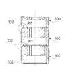
ピストンは、環状に形成されているので、部品製造工程を経てピストンを製造した後、組立工程を待つ在庫品として保管したり、組立工程へ移送したりするとき、図5に示すように、ピストン100を縦に積み重ねて取り扱うことが便利である。しかし、従来のピストン100を縦に積み重ねると、下側のピストン100の上側に形成されるシート面101に、上側のピストン100の下端となる脚部102が接触するので、この脚部102でシート面101を疵付け、所望の減衰力を得られなくなる虞がある。
Since the piston is formed in an annular shape, when the piston is manufactured through the parts manufacturing process and stored as an inventory waiting for the assembly process or transferred to the assembly process, as shown in FIG. It is convenient to stack 100 vertically and handle them. However, when the
そこで、本発明の目的は、ピストンを縦に積み重ねたとしても、重ね合わさる一方のピストンのシート面に他方のピストンの脚部が接触することを避け、シート面を保護することが可能なピストン及びこのピストンを備える緩衝器を提供することである。 Therefore, even if the pistons are stacked vertically, the object of the present invention is to prevent the leg portions of the other piston from coming into contact with the seat surfaces of one of the pistons to be overlapped, and to protect the seat surface. It is to provide a shock absorber provided with this piston.
上記課題を解決するための手段は、一方側に環板状のリーフバルブが積層される環状のピストンであって、一方側に形成されて上記リーフバルブが着座するシート面と、他方側の外周部分に周方向に沿って起立する脚部と、 上記シート面の外周に周方向に沿って設けられるとともに、上記シート面から外周側に他方側に傾斜しながら延びるスロープ部と、上記スロープ部の外周から外側に延びるフランジ部とを有する支持部とを備え、上記脚部の端部の内周側に窪みを設け、軸方向に重ねられたとき、上記脚部は、上記窪みにより上記シート面を避けて上記支持部に当接することを特徴とするピストンであり、また、このピストンを備えた緩衝器である。 Means for solving the above-mentioned problems are an annular piston in which an annular plate-like leaf valve is laminated on one side, a seat surface formed on one side on which the leaf valve is seated, and an outer periphery on the other side a leg portion erecting along the circumferential direction to the portion, a slope portion extending while tilting to the outer circumferential side on the other side to the outer circumference of the seat surface circumferential set only be along the Rutotomoni, from the sheet surface, the slope provided from the outer periphery of the parts and the support portion and a flange portion extending outwardly, is provided a recess on the inner peripheral side of the end portion of the leg, when superimposed on the axial direction, the leg, the by the recess It is a piston characterized in that it abuts against the support portion while avoiding the seat surface, and is a shock absorber provided with this piston.
本発明によれば、ピストンを縦に積み重ねたとしても、重ね合わさる一方のピストンのシート面に他方のピストンの脚部が接触することを避け、シート面を保護することが可能となる。 According to the present invention, even if the pistons are stacked vertically, it is possible to prevent the leg portions of the other piston from coming into contact with the seat surfaces of the one piston to be overlapped and to protect the seat surface.
以下に本発明の一実施の形態に係るピストンについて、図面を参照しながら説明する。いくつかの図面を通して付された同じ符号は、同じ部品か対応する部品を示す。 A piston according to an embodiment of the present invention will be described below with reference to the drawings. The same reference numerals given throughout the several drawings indicate the same or corresponding parts.
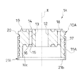
図1に示すように、本発明の一実施の形態に係るピストン1は、一方側に環板状のリーフバルブ7が積層される環状のピストンであって、一方側に形成されて上記リーフバルブ7が着座するシート面19と、他方側の外周部分に周方向に沿って起立する脚部10bとを備えており、上記シート面19の外周に周方向に沿って支持部20を設けるとともに、上記脚部10bの端部21の内周側に窪み21aを設け、上記ピストン1が軸方向に重ねられたとき上記脚部10bが上記シート面19aを避けて上記支持部20に当接する。
As shown in FIG. 1, a
本実施の形態において、上記ピストン1は、片ロッド単筒型に設定される緩衝器Dに利用されており、この緩衝器Dは、シリンダ2と、このシリンダ2内に摺動自在に挿入されるピストン1と、一端がピストン1に連結されてシリンダ2内に移動自在に挿入されるピストンロッド3と、シリンダ2内に上記ピストン1で区画した伸側室4及び圧側室5とを備えて構成されている。また、伸側室4及び圧側室5には作動油等の液体からなる作動流体が充満されている。作動流体は、作動油以外にも、例えば、水、水溶液といった液体を使用することもできる。さらに、図示しないが、シリンダ2内にはフリーピストンが摺動自在に挿入されており、シリンダ2内に出没するピストンロッド体積分のシリンダ内容積変化を補償する気室を区画している。なお、上記気室をブラダ等の弾性隔壁で区画するとしてもよい。また、シリンダ2の外周に外筒を設けて緩衝器Dを複筒型に設定し、シリンダ2と外筒との間に形成される筒状隙間に作動流体と気体とを収容するリザーバを形成するとしてもよく、この場合、リザーバでピストンロッド体積分のシリンダ内容積変化を補償することができる。さらに、緩衝器Dは、片ロッド型ではなく、両ロッド型に設定されてもよい。
In the present embodiment, the
ピストン1の両側には、複数枚の環板状のリーフバルブ6,7がそれぞれ積層されており、これらは、ピストン1とともにピストンロッド3の先端部外周に内周部をナット8で固定されている。以下、上記リーフバルブ6,7のうち、圧側室側(図1中下側)に積層されるリーフバルブを伸側のリーフバルブ6、伸側室側(図1中上側)に積層されるリーフバルブを圧側のリーフバルブ7とする。
A plurality of annular plate-
本発明は、上記ピストン1の構成に関するものであり、以下、本実施の形態のピストン1の構成について詳細に説明する。ピストン1は、ピストンロッド3の外周に保持される環状のピストン本体10と、このピストン本体10の外周に取り付けられてシリンダ2の内周面に摺接するピストンリング11とを備えて構成されている。
The present invention relates to the configuration of the
ピストン本体10は、図2に示すように、軸心部を貫通しピストンロッド3が挿通される中心孔12及び伸側室4と圧側室5とを連通する流路13,17が形成されるディスク部10aと、このディスク部10aの外周部から圧側室側(図2中下側)に延びる環状の脚部10bとを備えている。流路13,17は、ディスク部10aの内周側に軸方向に沿って形成される伸側の流路13と、ディスク部10aの外周側に軸方向に沿って形成される圧側の流路17とからなる。ディスク部10aの伸側室側(図2中上側)には、伸側の流路13の始端が連なる環状の開口窓14と、圧側の流路17の終端が連なる環状の窓18と、この窓18を囲う環状のシート面19と、このシート面19から外周側に張り出す支持部20とが形成されている。他方、ディスク部10aの圧側室側(図2中下側)には、伸側の流路13の終端が連なる窓15と、この開口窓15を囲う環状のシート面16とが形成されており、このシート面16と脚部10bの間に圧側の流路17の始端が連なっている。各シート面16,19は、平滑面であり、シート面16,19にリーフバルブ6,7が着座すると、窓15,18が塞がれるので流路13,17が閉じられるが、シート面16,19からリーフバルブ6,7が離れると、流路13,17が開放される。また、伸側のリーフバルブ6は、圧側の流路17の始端を塞がないように設定されるとともに、圧側のリーフバルブ7は、伸側の流路13が連なる開口窓14を常に塞がないようになっている。
As shown in FIG. 2, the piston
そして、外力の入力によりシリンダ2に対してピストンロッド3が図1中上側に相対移動させられて、緩衝器Dが伸長すると、ピストン1がピストンロッド3とともに図1中上側に移動して伸側室4を圧縮するので、伸側室4の作動流体が伸側のリーフバルブ6を押し開き、伸側の流路13を通過して圧側室5に移動する。このため、緩衝器Dは、作動流体が伸側の流路13を通過する際の伸側のリーフバルブ6の抵抗に起因する減衰力を発生する。反対に、外力の入力によりシリンダ2に対してピストンロッド3が図1中下側に相対移動させられて、緩衝器Dが収縮すると、ピストン1がピストンロッド3とともに図1中下側に移動して圧側室5を圧縮するので、圧側室5の作動流体が圧側のリーフバルブ7を押し開き、圧側の流路17を通過して伸側室4に移動する。このため、緩衝器Dは、作動流体が圧側の流路17を通過する際の圧側のリーフバルブ7の抵抗に起因する減衰力を発生する。
When the
もどって、ピストン本体10の脚部10bにおいて反ディスク部側(図1,2中下側)に位置する端部21は、その内周が軸方向に均一に拡径されて他の部分との境界に段差面を形成しており、これにより、上記端部21の内周側に周方向に沿って環状の窪み21aが形成されている。また、ピストン本体10において脚部10bの反対側に配置される支持部20は、図2に示すように、シート面19の外周から外側に図2中下側に傾斜しながら延びるスロープ部20aと、このスロープ部20aの外周から外側に延びるフランジ部20bとを備えており、このフランジ部20bは、ピストン1の中心線Xに対して垂直方向に延び、シート面19の外周に周方向に沿って配置されている。そして、脚部10bの窪み21aとフランジ部20bは、上記ピストン1の中心線X上に中心を有する同心円の円周上に配置されるとともに、脚部10bにおける端部21の内径w1が上記フランジ部20bの内径w2以上に設定され、上記窪み21aの軸方向長さh1がフランジ部20bから突出するシート面19aの軸方向長さh2よりも長くなるように設定されているので、ピストン1を軸方向に重ねたとき、重なり合う一方のピストン1の脚部10bの先端21が他方のピストン1の支持部20のフランジ部20bに当接し、脚部10bがシート面19に接触しない。なお、窪み21aや支持部20の形状や寸法は、ピストン1が軸方向に重ねられたとき、脚部10bがこの脚部10bの反対側に配置されるシート面19を避けて支持部20に当接させることができる限りにおいて、適宜設定することが可能である。例えば、脚部10bの端部21をスロープ部20aに当接させるとしてもよく、この場合、上記窪み21aの軸方向長さh1が支持部20から突出するシート面19の軸方向長さh2よりも短くてもよい。
Returning, the
ピストン本体10の外周に取り付けられるピストンリング11は、樹脂で形成されており、モールド成形によりピストン本体1の外周に固定されている。具体的には、図3に示すように、ピストン本体10の図3中下端部外周にピストンリング11の母材である環板状の樹脂シート11aを係合し、加熱シリンダH内に押し込むことにより、樹脂シート11aを加熱して変形させピストン本体10の外周に圧着させた後冷却する。本実施の形態において、ピストン本体10を縦に複数重ねた状態で、加熱シリンダH内に押し込むようにしているが、シート面19を避けて脚部10bを支持部20に当接させているので、重なり合うピストン本体10に軸方向に力を加えても、シート面19に力がかからず、シート面19を疵付ける心配がない。
The
次に、本実施の形態におけるピストン1の作用効果について説明する。上記ピストン1は、伸側室側(一方側)に環板状の圧側のリーフバルブ(リーフバルブ)7が積層される環状のピストンであって、伸側室側(一方側)に形成されて上記圧側のリーフバルブ7が着座するシート面19と、圧側室側(他方側)の外周部分に周方向に沿って起立する脚部10bとを備えており、上記シート面19の外周に周方向に沿って支持部20を設けるとともに、上記脚部10bの端部21の内周側に窪み21aを設け、上記ピストン1が軸方向に重ねられたとき上記脚部10bが上記シート面19を避けて上記支持部20に当接する。
Next, the effect of the
したがって、ピストン1を縦に積み重ねて保管したり、移送したりしても、重ね合わさる一方のピストン1のシート面19に他方のピストン1の脚部10bが接触することを避け、シート面19を保護することが可能となるので、ピストン1の保管及び移送時の利便性を向上させることができる。
Therefore, even if the
また、本実施の形態において、上記支持部20は、上記シート面19から外周側に圧側室側(他方側)に傾斜しながら延びるスロープ部20aと、このスロープ部20aの外周から外側に延びるフランジ部20bとを備えており、このフランジ部20bは、上記ピストン1の中心線Xに対して垂直方向に延び上記シート面19の外周に周方向に沿って配置されている。
Further, in the present embodiment, the
そして、上記窪み21aと上記フランジ部20bは、上記中心線X上に中心を有する同心円の円周上に配置されるとともに、上記脚部10bの端部21の内径w1が上記フランジ部20bの内径w2以上に設定され、上記窪み21aの軸方向長さh1が上記フランジ部20bから突出するシート面19の軸方向長さh2よりも長くなるように設定されている。
And the said hollow 21a and the said
したがって、重ね合わさる一方のピストン1のシート面19に他方のピストン1の脚部10bが接触することを避けるとともに、一方のピストン1の支持部20におけるフランジ部20bに脚部10bを当接させることができ、ピストン1を重ね合わせたときにピストン1が安定する。
Accordingly, the
また、上記実施の形態においては、上記脚部10bの端部21及び上記フランジ部20bが環状に形成されている。
Moreover, in the said embodiment, the
したがって、ピストン1を重ね合わせたとき、脚部10bと支持部20の接触面積を大きくすることが可能となる。
Therefore, when the
また、上記実施の形態において、ピストン1は、上記シート面19を備えるピストン本体10と、このピストン本体10の外周にモールド成形により取り付けられるピストンリング11とを備えている。
Moreover, in the said embodiment, the
上記モールド成形によれば、ピストン本体10を複数重ねて加熱シリンダH内に押し込む場合、従来のようにシート面101に脚部102が当接した状態では、脚部102がシート面101に強く押し付けられるので、シート面101を疵付ける可能性が大きくなる。そこで、シート面19を避けて脚部10bを支持部20に当接させることが特に有効である。さらに、この場合、ピストン1を重ねたときにフランジ部20bに脚部10bを当接させて安定させたり、脚部10bと支持部20の接触面積を大きくしたりすることが好ましい。
According to the above molding, when a plurality of piston
また、本実施の形態において、ピストン1は、緩衝器Dに利用されており、緩衝器Dは、筒状のシリンダ2と、このシリンダ2内に軸方向に移動可能に挿入されるピストンロッド3と、このピストンロッド3に保持されて上記シリンダ2の内周面に摺接するピストン1と、上記シリンダ2内に上記ピストン1で区画されて作動流体が充填される伸側室4及び圧側室5(二つの部屋)と、上記ピストン1に形成されて伸側室4と圧側室5(二つの部屋)を連通する圧側の流路(流路)17と、上記ピストン1の伸側室側(一方側)に積層されて上記圧側の流路17を通過する作動流体に抵抗を与える環板状の圧側のリーフバルブ(リーフバルブ)7とを備えており、この圧側のリーフバルブ7の抵抗に起因する減衰力を発生する。
In the present embodiment, the
したがって、圧側のリーフバルブ7が着座するシート面19に疵がつくと、この疵の部分から作動流体が漏れて、減衰力が変化する虞があるので、ピストン1を重ねたとき、シート面19を避けて脚部10bを支持部20に当接させ、シート面を保護することが上記緩衝器Dにおいては特に有効である。また、緩衝器Dを製造するにあたり、緩衝器Dの部品であるピストン1の保管及び移送時の利便性を向上させることが好ましい。
Accordingly, if the
以上、本発明の好ましい実施の形態を詳細に説明したが、特許請求の範囲から逸脱することなく改造、変形及び変更を行うことができることは理解すべきである。 Although preferred embodiments of the present invention have been described in detail above, it should be understood that modifications, variations and changes may be made without departing from the scope of the claims.
例えば、ピストン1の構成や、形状、形成方法は上記の限りではなく、ピストン本体10にモールド成形以外の方法によってピストンリング11を取り付けるとしてもよい。また、脚部10bの端部21若しくは支持部20のフランジ部20bに一または複数の切欠きを設けてもよい。また、ピストン1を図4に示すように変更するとしてもよく、この変更例に係るピストン1Aは、ピストンリング11Aをピストン本体10Aから図4中下側に突出させている。そして、本発明に係る脚部10cがピストン本体10Aとピストンリング11Aとで構成されており、脚部10cの端部21Aがピストン本体10Aから突出するピストンリング11Aで構成されている。このため、上記ピストン1Aでは、ピストンリング11Aとピストン本体10Aの段差部分21bを本発明の窪みとして利用することができる。
For example, the configuration, shape, and formation method of the
D 緩衝器
X ピストンの中心線
w1 脚部の端部の内径
h1 窪みの軸方向長さ
h2 上記フランジ部から突出するシート面の軸方向長さ
1,1A ピストン
2 シリンダ
3 ピストンロッド
4 伸側室(部屋)
5 圧側室(部屋)
7 圧側のリーフバルブ(リーフバルブ)
10,10A ピストン本体
10b,10c 脚部
11,11A ピストンリング
17 圧側の流路(流路)
19 シート面
20 支持部
20a スロープ部
20b フランジ部
21,21A 脚部の端部
21a,21b 窪み
D shock absorber X piston center line w1 inner diameter h1 of leg end axial length h2 hollow axial length h2 axial length of seat surface protruding from the
5 Pressure side room (room)
7 Pressure side leaf valve (leaf valve)
10, 10A Piston
19
Claims (6)
一方側に形成されて上記リーフバルブが着座するシート面と、
他方側の外周部分に周方向に沿って起立する脚部と、
上記シート面の外周に周方向に沿って設けられるとともに、上記シート面から外周側に他方側に傾斜しながら延びるスロープ部と、上記スロープ部の外周から外側に延びるフランジ部とを有する支持部とを備え、
上記脚部の端部の内周側に窪みを設け、
軸方向に重ねられたとき、上記脚部は、上記窪みにより上記シート面を避けて上記支持部に当接する
ことを特徴とするピストン。 An annular piston with an annular plate-like leaf valve laminated on one side,
A seat surface formed on one side on which the leaf valve is seated;
Legs that stand up in the circumferential direction on the outer peripheral portion on the other side ;
Support having an outer peripheral set only be along the circumferential direction Rutotomoni of the seat surface, and a slope portion extending while tilting on the other side to the outer circumferential side from the sheet surface, and a flange portion extending outwardly from the outer periphery of the slope portion With
A recess is provided on the inner peripheral side of the end of the leg,
When stacked in the axial direction, the leg, the piston, characterized in that the contact to the support portion to avoid the sheet surface by said recess.
上記窪みと上記フランジ部は、上記中心線上に中心を有する同心円の円周上に配置されるとともに、上記脚部の端部の内径が上記フランジ部の内径以上に設定され、上記窪みの軸方向長さが上記フランジ部から突出する上記シート面の軸方向長さよりも長くなるように設定されている
ことを特徴とする請求項1に記載のピストン。 The flange portion extends in a direction perpendicular to the center line of the piston and is disposed along the circumferential direction on the outer periphery of the seat surface.
The recess and the flange portion are arranged on a circumference of a concentric circle having a center on the center line, and an inner diameter of an end portion of the leg portion is set to be equal to or larger than an inner diameter of the flange portion, and the axial direction of the recess 2. The piston according to claim 1, wherein a length is set to be longer than an axial length of the seat surface protruding from the flange portion.
ことを特徴とする請求項2に記載のピストン。 The piston according to claim 2, wherein an end portion of the leg portion and the flange portion are formed in an annular shape.
上記脚部は、上記ピストンリングによって構成され、The leg is constituted by the piston ring,
上記窪みは、上記ピストンリングと上記ピストン本体の上記他方側の端部の段差部分で形成されるThe recess is formed by a step portion at the other end of the piston ring and the piston body.
ことを特徴とする請求項1から請求項3の何れか一項に記載のピストン。The piston according to any one of claims 1 to 3, wherein:
ことを特徴とする請求項1から請求項3の何れか一項に記載のピストン。 A piston body having the seat surface, the piston according to claims 1 to any one of claims 3, characterized in that it comprises a piston ring which is attached by molding the outer circumference of the piston body.
上記シリンダ内に軸方向に移動可能に挿入されるピストンロッドと、
上記ピストンロッドに保持されて上記シリンダの内周面に摺接する請求項1から請求項5のいずれか一項に記載のピストンと、
上記シリンダ内に上記ピストンで区画されて作動流体が充填される二つの部屋と、
上記ピストンに形成されて上記二つの部屋を連通する流路と、
上記ピストンの一方側に積層されて上記流路を通過する作動流体に抵抗を与える環板状のリーフバルブとを備え、
上記リーフバルブの抵抗に起因する減衰力を発生する
緩衝器。 A cylindrical cylinder;
A piston rod inserted in the cylinder so as to be movable in the axial direction;
The piston according to any one of claims 1 to 5, wherein the piston is held by the piston rod and is in sliding contact with the inner peripheral surface of the cylinder.
Two chambers defined by the piston in the cylinder and filled with working fluid;
A flow path formed in the piston and communicating the two chambers;
Are stacked on one side of the piston example Bei a ring-shaped leaf valve that provide resistance to the working fluid passing through the flow path,
Damper for generating a damping force due to the resistance of the leaf valve.
Priority Applications (5)
| Application Number | Priority Date | Filing Date | Title |
|---|---|---|---|
| JP2013020962A JP5746237B2 (en) | 2013-02-06 | 2013-02-06 | Piston and shock absorber with piston |
| US14/762,209 US9772000B2 (en) | 2013-02-06 | 2014-02-04 | Piston and shock absorber including piston |
| CN201480005095.4A CN104956117B (en) | 2013-02-06 | 2014-02-04 | Piston, and damper with piston |
| PCT/JP2014/052553 WO2014123114A1 (en) | 2013-02-06 | 2014-02-04 | Piston, and damper with piston |
| DE112014000706.4T DE112014000706T5 (en) | 2013-02-06 | 2014-02-04 | Piston and shock absorber with piston |
Applications Claiming Priority (1)
| Application Number | Priority Date | Filing Date | Title |
|---|---|---|---|
| JP2013020962A JP5746237B2 (en) | 2013-02-06 | 2013-02-06 | Piston and shock absorber with piston |
Publications (3)
| Publication Number | Publication Date |
|---|---|
| JP2014152812A JP2014152812A (en) | 2014-08-25 |
| JP2014152812A5 JP2014152812A5 (en) | 2015-05-07 |
| JP5746237B2 true JP5746237B2 (en) | 2015-07-08 |
Family
ID=51299708
Family Applications (1)
| Application Number | Title | Priority Date | Filing Date |
|---|---|---|---|
| JP2013020962A Active JP5746237B2 (en) | 2013-02-06 | 2013-02-06 | Piston and shock absorber with piston |
Country Status (5)
| Country | Link |
|---|---|
| US (1) | US9772000B2 (en) |
| JP (1) | JP5746237B2 (en) |
| CN (1) | CN104956117B (en) |
| DE (1) | DE112014000706T5 (en) |
| WO (1) | WO2014123114A1 (en) |
Families Citing this family (1)
| Publication number | Priority date | Publication date | Assignee | Title |
|---|---|---|---|---|
| JP6594226B2 (en) | 2016-02-25 | 2019-10-23 | 株式会社ショーワ | Pressure buffer device and flow path forming member |
Family Cites Families (15)
| Publication number | Priority date | Publication date | Assignee | Title |
|---|---|---|---|---|
| US3212411A (en) * | 1964-02-14 | 1965-10-19 | Duriron Co | Fluid tight self-lubricating cylinder assembly |
| US3730305A (en) * | 1971-04-16 | 1973-05-01 | Ford Motor Co | Shock absorber piston |
| JPH051709Y2 (en) * | 1988-08-06 | 1993-01-18 | ||
| US5325942A (en) * | 1991-03-14 | 1994-07-05 | Monroe Auto Equipment Company | Tunable hydraulic valve for shock absorber |
| JPH08135713A (en) | 1994-11-14 | 1996-05-31 | Toyota Motor Corp | Hydraulic shock absorber |
| FR2738889B1 (en) * | 1995-09-20 | 1997-10-31 | Soframca | VALVE PISTON FOR HYDRAULIC SHOCK ABSORBER TUBE |
| JP2000257659A (en) * | 1999-03-10 | 2000-09-19 | Showa Corp | Piston for hydraulic shock absorber and piston oil passage forming method |
| US6371264B1 (en) * | 1999-06-09 | 2002-04-16 | Denso Corporation | Fulcrum blow off valve for use in a shock absorber |
| DE10318018B4 (en) * | 2002-05-24 | 2015-06-11 | Zf Friedrichshafen Ag | Kolbendämpfventil |
| US6886670B2 (en) * | 2003-09-29 | 2005-05-03 | Tenneco Automotive Operating Company Inc. | Extra support land for valve disc |
| DE102004050732A1 (en) * | 2003-12-01 | 2005-06-23 | Zf Friedrichshafen Ag | Damping valve assembly for vehicle, has control slide moving in closing direction to close throttle, where slide includes pressure-actuated surface which acts in closing direction as function of flow velocity of damping medium |
| DE102004058965B4 (en) * | 2004-12-08 | 2010-07-08 | Zf Friedrichshafen Ag | Vibration damper with amplitude-selective damping force |
| CN201507641U (en) * | 2009-09-23 | 2010-06-16 | 万向集团公司 | Piston of pressure groove at piston valve line |
| CN201858350U (en) * | 2010-08-31 | 2011-06-08 | 浙江万向系统有限公司 | Novel piston and piston ring |
| JP5588497B2 (en) | 2012-11-16 | 2014-09-10 | カヤバ工業株式会社 | Piston and shock absorber |
-
2013
- 2013-02-06 JP JP2013020962A patent/JP5746237B2/en active Active
-
2014
- 2014-02-04 CN CN201480005095.4A patent/CN104956117B/en not_active Expired - Fee Related
- 2014-02-04 DE DE112014000706.4T patent/DE112014000706T5/en not_active Withdrawn
- 2014-02-04 WO PCT/JP2014/052553 patent/WO2014123114A1/en active Application Filing
- 2014-02-04 US US14/762,209 patent/US9772000B2/en active Active
Also Published As
| Publication number | Publication date |
|---|---|
| US20150345584A1 (en) | 2015-12-03 |
| CN104956117A (en) | 2015-09-30 |
| DE112014000706T5 (en) | 2015-10-22 |
| US9772000B2 (en) | 2017-09-26 |
| WO2014123114A1 (en) | 2014-08-14 |
| CN104956117B (en) | 2017-05-10 |
| JP2014152812A (en) | 2014-08-25 |
Similar Documents
| Publication | Publication Date | Title |
|---|---|---|
| KR20110098630A (en) | Buffer | |
| JP6412339B2 (en) | Shock absorber | |
| JP2017002968A (en) | Pressure buffer device and elastic member | |
| JP5746237B2 (en) | Piston and shock absorber with piston | |
| JP5997070B2 (en) | Shock absorber | |
| JP5783646B2 (en) | valve | |
| JP6487804B2 (en) | Buffer valve structure | |
| WO2016013129A1 (en) | Piston and damper | |
| JP2007120726A (en) | Hydraulic shock absorber | |
| JP6360291B2 (en) | Buffer valve structure | |
| JP5783647B2 (en) | valve | |
| JP6128652B2 (en) | Shock absorber | |
| JP2015135147A (en) | shock absorber | |
| JP6594226B2 (en) | Pressure buffer device and flow path forming member | |
| JP6357084B2 (en) | Variable rigidity device | |
| JP6343542B2 (en) | shock absorber | |
| JP2010054009A (en) | Shock absorber | |
| JP6443985B2 (en) | Cylinder device | |
| JP5798842B2 (en) | Shock absorber | |
| JP5618415B2 (en) | piston | |
| JP6006621B2 (en) | Shock absorber | |
| JP6401862B2 (en) | piston | |
| JP5851167B2 (en) | Cylinder device | |
| JP6487815B2 (en) | shock absorber | |
| JP6434735B2 (en) | Shock absorber manufacturing method |
Legal Events
| Date | Code | Title | Description |
|---|---|---|---|
| A521 | Request for written amendment filed |
Free format text: JAPANESE INTERMEDIATE CODE: A523 Effective date: 20150320 |
|
| A621 | Written request for application examination |
Free format text: JAPANESE INTERMEDIATE CODE: A621 Effective date: 20150320 |
|
| A871 | Explanation of circumstances concerning accelerated examination |
Free format text: JAPANESE INTERMEDIATE CODE: A871 Effective date: 20150320 |
|
| TRDD | Decision of grant or rejection written | ||
| A975 | Report on accelerated examination |
Free format text: JAPANESE INTERMEDIATE CODE: A971005 Effective date: 20150409 |
|
| A01 | Written decision to grant a patent or to grant a registration (utility model) |
Free format text: JAPANESE INTERMEDIATE CODE: A01 Effective date: 20150414 |
|
| A61 | First payment of annual fees (during grant procedure) |
Free format text: JAPANESE INTERMEDIATE CODE: A61 Effective date: 20150507 |
|
| R151 | Written notification of patent or utility model registration |
Ref document number: 5746237 Country of ref document: JP Free format text: JAPANESE INTERMEDIATE CODE: R151 |
|
| S533 | Written request for registration of change of name |
Free format text: JAPANESE INTERMEDIATE CODE: R313533 |
|
| R350 | Written notification of registration of transfer |
Free format text: JAPANESE INTERMEDIATE CODE: R350 |
|
| S533 | Written request for registration of change of name |
Free format text: JAPANESE INTERMEDIATE CODE: R313533 |
|
| R350 | Written notification of registration of transfer |
Free format text: JAPANESE INTERMEDIATE CODE: R350 |