JP5746142B2 - Medical tray - Google Patents
Medical tray Download PDFInfo
- Publication number
- JP5746142B2 JP5746142B2 JP2012503031A JP2012503031A JP5746142B2 JP 5746142 B2 JP5746142 B2 JP 5746142B2 JP 2012503031 A JP2012503031 A JP 2012503031A JP 2012503031 A JP2012503031 A JP 2012503031A JP 5746142 B2 JP5746142 B2 JP 5746142B2
- Authority
- JP
- Japan
- Prior art keywords
- side wall
- medical tray
- bottom portion
- folding
- medical
- Prior art date
- Legal status (The legal status is an assumption and is not a legal conclusion. Google has not performed a legal analysis and makes no representation as to the accuracy of the status listed.)
- Active
Links
- 238000012423 maintenance Methods 0.000 claims description 3
- 230000009466 transformation Effects 0.000 claims description 3
- 230000000994 depressogenic effect Effects 0.000 claims description 2
- 239000010813 municipal solid waste Substances 0.000 description 8
- 238000011282 treatment Methods 0.000 description 8
- 239000012790 adhesive layer Substances 0.000 description 7
- 239000003814 drug Substances 0.000 description 5
- 229940079593 drug Drugs 0.000 description 4
- 238000005452 bending Methods 0.000 description 3
- 238000003745 diagnosis Methods 0.000 description 3
- 238000004806 packaging method and process Methods 0.000 description 3
- 229920000742 Cotton Polymers 0.000 description 2
- 238000007689 inspection Methods 0.000 description 2
- 230000004048 modification Effects 0.000 description 2
- 238000012986 modification Methods 0.000 description 2
- -1 polyethylene Polymers 0.000 description 2
- 239000002699 waste material Substances 0.000 description 2
- 239000004698 Polyethylene Substances 0.000 description 1
- 239000004743 Polypropylene Substances 0.000 description 1
- 239000004793 Polystyrene Substances 0.000 description 1
- 230000000694 effects Effects 0.000 description 1
- 230000009191 jumping Effects 0.000 description 1
- 238000000034 method Methods 0.000 description 1
- 238000000465 moulding Methods 0.000 description 1
- 229920000573 polyethylene Polymers 0.000 description 1
- 229920001155 polypropylene Polymers 0.000 description 1
- 229920002223 polystyrene Polymers 0.000 description 1
- 229920000915 polyvinyl chloride Polymers 0.000 description 1
- 239000004800 polyvinyl chloride Substances 0.000 description 1
- 230000001105 regulatory effect Effects 0.000 description 1
- 230000002787 reinforcement Effects 0.000 description 1
- 229920005989 resin Polymers 0.000 description 1
- 239000011347 resin Substances 0.000 description 1
- 229920005992 thermoplastic resin Polymers 0.000 description 1
Images


Classifications
-
- A—HUMAN NECESSITIES
- A61—MEDICAL OR VETERINARY SCIENCE; HYGIENE
- A61M—DEVICES FOR INTRODUCING MEDIA INTO, OR ONTO, THE BODY; DEVICES FOR TRANSDUCING BODY MEDIA OR FOR TAKING MEDIA FROM THE BODY; DEVICES FOR PRODUCING OR ENDING SLEEP OR STUPOR
- A61M25/00—Catheters; Hollow probes
- A61M25/002—Packages specially adapted therefor ; catheter kit packages
-
- A—HUMAN NECESSITIES
- A61—MEDICAL OR VETERINARY SCIENCE; HYGIENE
- A61B—DIAGNOSIS; SURGERY; IDENTIFICATION
- A61B50/00—Containers, covers, furniture or holders specially adapted for surgical or diagnostic appliances or instruments, e.g. sterile covers
- A61B50/30—Containers specially adapted for packaging, protecting, dispensing, collecting or disposing of surgical or diagnostic appliances or instruments
- A61B50/33—Trays
-
- A—HUMAN NECESSITIES
- A61—MEDICAL OR VETERINARY SCIENCE; HYGIENE
- A61B—DIAGNOSIS; SURGERY; IDENTIFICATION
- A61B50/00—Containers, covers, furniture or holders specially adapted for surgical or diagnostic appliances or instruments, e.g. sterile covers
- A61B50/30—Containers specially adapted for packaging, protecting, dispensing, collecting or disposing of surgical or diagnostic appliances or instruments
- A61B50/36—Containers specially adapted for packaging, protecting, dispensing, collecting or disposing of surgical or diagnostic appliances or instruments for collecting or disposing of used articles
-
- A—HUMAN NECESSITIES
- A61—MEDICAL OR VETERINARY SCIENCE; HYGIENE
- A61B—DIAGNOSIS; SURGERY; IDENTIFICATION
- A61B17/00—Surgical instruments, devices or methods, e.g. tourniquets
- A61B2017/0023—Surgical instruments, devices or methods, e.g. tourniquets disposable
Landscapes
- Health & Medical Sciences (AREA)
- Life Sciences & Earth Sciences (AREA)
- Surgery (AREA)
- Veterinary Medicine (AREA)
- General Health & Medical Sciences (AREA)
- Biomedical Technology (AREA)
- Heart & Thoracic Surgery (AREA)
- Engineering & Computer Science (AREA)
- Public Health (AREA)
- Animal Behavior & Ethology (AREA)
- Medical Informatics (AREA)
- Molecular Biology (AREA)
- Nuclear Medicine, Radiotherapy & Molecular Imaging (AREA)
- Biophysics (AREA)
- Pulmonology (AREA)
- Anesthesiology (AREA)
- Hematology (AREA)
- Packages (AREA)
- Accommodation For Nursing Or Treatment Tables (AREA)
Description
本発明は、医療用トレイに関する。 The present invention relates to a medical tray.
カテーテル類を用いる診断、検査及び治療では、必要なカテーテルやガイドワイヤ等の医療器具や薬剤等が医療用トレイにセットされ、施術に当って医療用トレイ内から取り出されて用いられる。そして施術の後、不要になった医療用トレイはゴミ箱に捨てられる。 In diagnosis, inspection, and treatment using catheters, necessary medical devices such as catheters and guide wires, drugs, and the like are set on a medical tray, and are used by being taken out from the medical tray for treatment. After the treatment, the medical tray that is no longer needed is thrown into the trash.
医療現場で用いられるゴミ箱の容積は、焼却設備の投入口の形状に対応してある程度決まっており、また、廃棄処分にかかる費用はゴミ箱単位で決められていることが多いため、医療用トレイをできるだけコンパクトにしてより多くの医療用トレイがゴミ箱に入れられることが望ましい。例えば特許文献1に記載の医療用トレイは、側壁を底面に重ね合わせるように折り畳むことによって廃棄の際にコンパクトにできる。
The volume of the trash can used at the medical site is determined to some extent according to the shape of the inlet of the incinerator, and the cost for disposal is often determined by the trash can. It is desirable to make it as compact as possible so that more medical trays can be placed in the trash. For example, the medical tray described in
しかし、一般的に医療用トレイでは底部が側壁に比べて広く、医療用トレイ全体に占める底部の面積割合が大きいため、特許文献1に記載の医療用トレイのように側壁を折り畳んだだけでは、ゴミ箱内で医療用トレイが嵩張り易い。
However, in general, the bottom of the medical tray is wider than the side wall, and since the area ratio of the bottom of the entire medical tray is large, just folding the side wall like the medical tray described in
本発明はこのような課題に鑑みてなされたものであり、廃棄の際によりコンパクトにできる医療用トレイを提供することを目的とする。 This invention is made | formed in view of such a subject, and it aims at providing the medical tray which can be made compact at the time of disposal.
上記目的を達成するための本発明の医療用トレイは、底部と、当該底部の外周に沿って設けられる側壁と、当該側壁の対向する位置に設けられ、前記側壁が前記底部に向かって前記側壁の内側に凸状に変形するのを案内する一対の側壁変形案内部と、を有し、前記側壁変形案内部は、前記側壁の上端から前記底部に向かって延び、前記側壁の内側に窪んで形成された側壁溝部を有する。 Medical tray of the present invention for achieving the above object, a bottom, a side wall provided along the outer periphery of the bottom, provided at a position opposite of the side walls, said side walls said side walls toward the bottom possess a pair of side walls deformable guide portion for guiding the deformation inwardly convex, and said side wall deformation guiding portion extends from the upper end of the side wall toward the bottom, recessed inwardly of the side wall It has the formed side wall groove part .
上記のように構成した本発明の医療用トレイは、側壁変形案内部を有するため側壁が底部に向かって凸形状に変形し、底部を折り畳む際、力が底部に局所的に加わり易く、底部が容易に折り畳まれて医療用トレイをよりコンパクトにできる。 Since the medical tray of the present invention configured as described above has a side wall deformation guide portion, the side wall is deformed into a convex shape toward the bottom portion, and when the bottom portion is folded, a force is easily applied locally to the bottom portion. It can be easily folded to make the medical tray more compact.
また、前記側壁変形案内部は、前記底部の幅が内側に窪んで形成されたくびれ部、前記側壁の上端が前記底部に向かって窪んで形成された側壁上端凹部若しくは前記側壁の上端が前記底部に向かって段状に形成された側壁上端段差部、及び前記側壁の上端に形成されたフランジが前記側壁の内側に窪んで形成されるフランジ溝部のうちの少なくとも1つを含むようにすれば、側壁が局所的に屈曲し、側壁を変形させ易い。 Further, the side wall deformation guiding portion, said bottom constricted portion width is formed to be recessed inward of the upper end of the front SL upper end the bottom side wall upper recess or the side wall which is recessed in form towards the end of the side wall the If the side wall upper end step portion formed stepwise toward the bottom portion and the flange formed at the upper end of the side wall include at least one of a flange groove portion formed to be recessed inside the side wall. The side wall is locally bent and the side wall is easily deformed.
また、前記一対の側壁変形案内部の間の前記底部に設けられ、前記底部の折り畳みを案内する折り畳み案内部をさらに有するようにすれば、前記一対の側壁変形案内部を結ぶライン又はその近傍で底部が折り曲げられ、所望の方向に底部を折り畳み易い。 In addition, if it further includes a folding guide provided at the bottom between the pair of side wall deformation guides and guides the folding of the bottom, at or near the line connecting the pair of side wall deformation guides The bottom part is bent, and the bottom part is easily folded in a desired direction.
また、前記折り畳み案内部は、前記底部における前記一対の側壁変形案内部の間に形成されたリブ若しくは切れ込み、及び前記底部の縁が面方向に窪んで形成された底縁凹部若しくは前記底部の縁が面方向に段状に形成された底縁段差部のうちの少なくとも1つを含むようにすれば、前記一対の側壁変形案内部を結ぶライン若しくはその近傍からずれた箇所での曲げが規制されるため、又は前記ライン若しくはその近傍で底部が脆弱になるため、前記一対の側壁変形案内部を結ぶライン又はその近傍で底部が折り曲げられ、所望の方向に底部を折り畳み易い。 Further, the folding guide part is a rib or notch formed between the pair of side wall deformation guide parts in the bottom part, and a bottom edge recessed part or an edge of the bottom part in which an edge of the bottom part is recessed in a surface direction. If at least one of the bottom edge step portions formed stepwise in the surface direction is included, bending at a position deviating from the line connecting the pair of side wall deformation guide portions or the vicinity thereof is regulated. For this reason, or because the bottom portion becomes weak at or near the line, the bottom portion is bent at or near the line connecting the pair of side wall deformation guide portions, and the bottom portion is easily folded in a desired direction.
前記底部が折り畳まれる際、前記側壁のうちの対向する対面部のうちの一方が他方の内側に入れ込まれるようにすれば、折り畳まれて2分された医療用トレイの一方が他方に納まり、医療用トレイがよりコンパクトになる。 When the bottom part is folded, if one of the opposing facing parts of the side walls is inserted inside the other, one of the folded medical trays is stored in the other, The medical tray becomes more compact.
前記一対の側壁変形案内部を結ぶラインで分けられる前記底部の一端側の大きさが、他端側の内側に収まる大きさであるようにすれば、医療用トレイを折り畳んだ際、折り畳まれて2分された医療用トレイの一端側が他端側に納まり、医療用トレイがよりコンパクトになる。 If the size of one end side of the bottom portion divided by the line connecting the pair of side wall deformation guide portions is a size that fits inside the other end side, it is folded when the medical tray is folded. One end side of the divided medical tray is accommodated in the other end side, and the medical tray becomes more compact.
前記一対の側壁変形案内部を結ぶラインで分けられる前記底部の一端側は、他端側よりも角が丸みを帯びているようにすれば、医療用トレイの一端側が他端側に更に納まり易くなる。 If one end side of the bottom portion divided by a line connecting the pair of side wall deformation guide portions is rounded more than the other end side, the one end side of the medical tray can be more easily fitted on the other end side. Become.
前記底部の折り畳みを維持する折り畳み維持部をさらに有するようにすれば、折り畳んだ医療用トレイが元の状態に広がり難く、コンパクトな状態を維持できる。 If the folding maintenance section for maintaining the folding of the bottom portion is further provided, the folded medical tray is difficult to expand to the original state, and a compact state can be maintained.
以下、図面を参照して本発明の実施形態を説明する。なお、図面の寸法比率は、説明の都合上、誇張されて実際の比率とは異なる場合がある。 Hereinafter, embodiments of the present invention will be described with reference to the drawings. In addition, the dimension ratio of drawing is exaggerated on account of description, and may differ from an actual ratio.
図1に示すように、本実施形態に係る医療用トレイ10は、底部11と、底部11の外周に沿って設けられる側壁12と、側壁12の上端に形成されたフランジ14と、を有する。また、医療用トレイ10は、側壁12の対向する位置に設けられた一対の側壁変形案内部20と、一対の側壁変形案内部20の間の底部11に設けられ、底部11の折り畳みを案内するリブ30(折り畳み案内部)と、を有する。
As shown in FIG. 1, the
医療用トレイ10は、薄肉の樹脂製であり、例えば、ポリエチレン、ポリプロピレン、ポリスチレン、ポリ塩化ビニル等の熱可塑性樹脂シートから真空成形等によって形成される。底部11、側壁12、フランジ14、側壁変形案内部20、及びリブ30は一体的に形成される。
The
医療用トレイ10は、底部11と、側壁12とによって形成する収納空間Sを備え、収納空間Sは、診断、検査及び治療の際、カテーテル等の医療器具や薬剤等を入れておくために用いられる。また、医療用トレイ10は、医療器具や薬剤等を包装するための包装トレイとしても用いることができ、必要な医療器具や薬剤等が予め医療用トレイ10に収納され、医療用トレイ10ごと包装袋に入れられ滅菌されてパッケージされる。
The
そして、図2及び図3に示すように、診断、検査及び治療の施術に際して包装袋が開封されることによって医療用トレイ10に医療器具や薬剤等がセットされた状態になる。医療器具は、カテーテル63、及びドレープ61の他、例えば、脱脂綿類、シリンジ、ガイドワイヤ、シース、ダイレータ、はさみ類、ピンセット等である。ドレープ61は、医療用トレイ10の上に載せられ、フランジ14に形成された突起部15によって位置決めされる。
As shown in FIGS. 2 and 3, the medical bag, the medicine, and the like are set on the
施術にあたり医療用トレイ10から医療器具が取り出され、また、施術中、医療器具が一時保管のために医療用トレイ10に入れられる。そして施術の後、不要となった医療器具は医療用トレイ10に入れられて医療用トレイ10とともに捨てられる。
During the treatment, the medical instrument is taken out from the
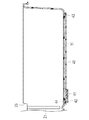
図4に示すように、底部11には、両端側に比べて、略中央付近(ラインL付近)の幅が狭く形成されたくびれ部(幅狭部)17が設けられている。底部11は、くびれ部17を有することにより、側壁12の略中央付近に設けられた側壁溝部21等に向かって縁が緩やかに窪んだ形状になっている。また、底部11の形状は、全体としては略長方形になっており、くびれ部17は、長辺側に設けられている。側壁変形案内部20は、底部11の長辺の中央から少しだけずれた位置にあり、一対の側壁変形案内部20を結ぶラインLで2分される底部11の一端側は、他端側の内側に収まる大きさであり、かつ、他端側よりも角が丸みを帯びている。
As shown in FIG. 4, the
側壁12は、底部11にくびれ部17が設けられていることにより、ラインL付近では対向する側壁12の間隔が両端側に比べて近づいている。
The
リブ30は、医療用トレイ10内側(収納空間S側)に突出して稜状に延びており、底部11に立体的に形成されたラインであり、ラインL上に形成される。底部11には、リブ30の他、収納される医療器具の配置を規制したり、または強度を付与したりするため、医療用トレイ10内側(収納空間S側)に突出して稜状に延び、底部11に立体的に形成された稜状部50が形成されている。本実施形態では、医療用トレイ10が、リブ30と交わる方向に形成された稜状部50を有するが、このようにリブ30と交わる場合、底部11の折り畳みを阻害しないように、稜状部50は好ましくはリブ30を挟んで両側に分割して形成される。また底部11には、底部11を折り畳んだ後に折り畳みを維持するための長尺状のテープ40(折り畳み維持部)が配置されている。
The
図4及び図5に示すように、側壁変形案内部20は、底部11の幅が内側に窪んで形成されたくびれ部17(図4参照)、フランジ14が側壁12の内側に窪んで形成されたフランジ溝部22(図4参照)、側壁12の上端から底部11に向かって延び側壁12の内側に窪んで形成された側壁溝部21(図5参照)、及び側壁12の上端が底部11に向かって窪んで形成された側壁上端凹部23(図5参照)から構成される。
As shown in FIGS. 4 and 5, the side wall
図6に示すように、テープ(折り畳み維持部)40は、その両端に設けられた接着層43、44によって底部11に接着されている。テープ40の一端は、底部11から外れないように接着層43によって固定されており、テープ40他端は、底部11から外せるように接着層44によって仮止めされている。また、テープ40は、接着層44が配置された面と反対側の面に設けられた接着層41を有する。接着層41は、接着を防ぐシート42によって覆われている。
As shown in FIG. 6, the tape (folding maintaining part) 40 is adhered to the
次に図7及び図8において医療用トレイ10の折り畳み方法について述べる。
Next, a method for folding the
概説すると、折り畳みを実施する作業者は、まず、側壁変形案内部20又はその近傍を押して側壁12を底部11に向かって押し倒し、その後、底部11を折って、医療用トレイ10を略半分に折り畳む。
In general, a worker who performs folding first pushes the side wall
図7に示すように例えば使用後のカテーテル63等の医療器具とともに医療用トレイ10を捨てるとき、押し倒した側壁12及び底部11によってカテーテル63を挟んで押えることによって、底部11を折り畳む際に、カテーテル63が弾性力によって跳ね出すのを防止できる。
As shown in FIG. 7, for example, when the
図8(A)示すように、押し潰された側壁12は側壁変形案内部20又はその近傍で底部11に向かって凸形状に変形する。そして、図8(B)に示すようにリブ30又はその近傍、すなわちラインL又はその近傍で底部11が折り畳まれ、図8(C)に示すように、側壁12のうちの対向する対面部のうちの一方15が他方16の内側に入れ込まれる。
As shown in FIG. 8A, the crushed
次に、図9(A)に示すように作業者は底部11に仮止めされたテープ40の一端を底部11から剥がすとともに、シート42を剥がす。その後図9(B)に示すように折り畳まれて2分された底部11の一方に接着層41によってテープ40の一端を接着し、底部11の折り畳みを維持する。
Next, as shown in FIG. 9A, the operator peels one end of the
その後、図10に示すように折り畳まれた状態で医療用トレイ10はゴミ箱に捨てられる。医療用トレイ10の各種寸法は適宜設定できるが、図10のように折り畳まれた医療用トレイ10がそのままゴミ箱に入れられる大きさであることが好ましく、医療現場で用いられるゴミ箱の開口部は略矩形形状であることが多いため、折り畳んだ後の底部11の長手方向の寸法S1及び短手方向の寸法S2は、ゴミ箱の開口部の長手方向及び短手方向の寸法より小さい。
Thereafter, the
本実施形態の効果を述べる。 The effect of this embodiment will be described.
上記従来の医療用トレイでは、本実施形態と異なり側壁の面が底面に重ね合わせるように折り畳まれるので、側壁が、底部に向かって凸状に変形するのではなく、底部から反れるように底部の面と略平行な方向に変形し、側壁と底部とが面と面で合わさる。 Unlike the present embodiment, the conventional medical tray is folded so that the surface of the side wall overlaps the bottom surface, so that the side wall is not deformed in a convex shape toward the bottom but is bent from the bottom. The side wall and the bottom portion are joined with each other in a direction substantially parallel to the surface.
一方、本実施形態は、側壁変形案内部20を有するため、側壁12が底部11に向かって凸形状に変形し、底部11を折り畳む際、ラインL又はその近傍に局所的に力が加わり易く、底部11が容易に折り畳まれて医療用トレイ10をよりコンパクトにできる。
On the other hand, since this embodiment has the side wall
また、本実施形態では、側壁変形案内部20が、くびれ部17、フランジ溝部22、側壁溝部21、及び側壁上端凹部23から構成されるため、側壁12が局所的に屈曲し、側壁12を変形させ易い。
Further, in the present embodiment, the side wall
また、医療用トレイ10では、側壁変形案内部20がフランジ溝部22を含むため、フランジ14による医療用トレイ10の補強と折り畳みの容易さという、相反する機能の両立を図り得る。
Moreover, in the
また、上記従来の医療用トレイでは、不要となった脱脂綿等の廃棄物を、側壁を折り畳むことによって覆い隠すため、側壁を高くしなければならず、医療用トレイが深くなり、医療器具の取り出し等、使用性が低下する虞がある。 Further, in the above-described conventional medical tray, waste such as absorbent cotton, which is no longer necessary, is covered by folding the side wall. Therefore, the side wall must be raised, the medical tray becomes deeper, and the medical instrument is taken out. There is a risk that the usability will be reduced.
一方、本実施形態では、底部11を折り畳むことによって廃棄物を覆うため、従来技術のような構造上の制約を受けず、側壁高さを自由に設定でき、使用性に優れた医療用トレイ10の実現を図り得る。
On the other hand, in the present embodiment, since the waste is covered by folding the
また、医療用トレイ10では、リブ30が、ラインL又はその近傍からずれた箇所での曲げを規制するため、底部11がラインL又はその近傍で折り曲げられ、所望の方向に折り畳み易い。
Moreover, in the
また、医療用トレイ10では、ラインLで2分される底部11の一方の大きさが他方の内側に収まる大きさで、また、底部11が折り畳まれる際、側壁12のうちの対向する対面部のうちの一方15が他方16の内側に入れ込まれるため、折り畳まれて2分された医療用トレイ10の一方が他方に納まり、医療用トレイ10がよりコンパクトになる。
Further, in the
また、テープ40が折り畳みを維持して医療用トレイ10が元の状態に広がり難く、コンパクトな状態を維持できる。
Further, the
本発明は、上述した実施形態に限定されるものではなく、特許請求の範囲の範囲内で種々改変できる。 The present invention is not limited to the above-described embodiments, and various modifications can be made within the scope of the claims.
例えば、折り畳み案内部は、リブ30に限定されず、ラインL上に形成され、曲げ剛性を低下させるものでもよく、一方面のみが凹状に窪むように形成された切れ込み(立体的に形成されたライン)でもよいし、図11、12に示すように、底部11の縁が面方向に窪んで形成される底縁凹部31、又は底部11の縁が面方向に段状に形成される底縁段差部32であってもよい。また、折り畳み案内部は、リブ30及び切れ込みのうちの一方と、底縁凹部31及び底縁段差部32のうちの一方とを組み合わせたものから構成されてもよい。
For example, the folding guide portion is not limited to the
また、折り畳み案内部は、上記実施形態のリブ30のような直線的なものに限定されず、曲がった箇所が含まれてもよい。すなわち、ラインLは、一対の側壁変形案内部を結ぶもので、直線的なものだけでなく曲がった箇所を有するものであってもよい。
Further, the folding guide portion is not limited to a linear one like the
また、上記実施形態では、側壁変形案内部が、くびれ部17、フランジ溝部22、側壁溝部21、及び側壁上端凹部23から構成されたが、これに限定されず、これらのうちのいずれか1つから構成されるもの、又はこれらのうちのいずれか2つから構成されるものであってもよい。
Moreover, in the said embodiment, although the side wall deformation | transformation guide part was comprised from the
また、くびれ部17は、底部11の幅が一端側から略中央付近に向かって内側に狭まり、略中央付近から他端側に向かって外側に広がっている形状となっているが、底部11の幅が一端側から略中央付近に向かって内側に狭まり、略中央付近から他端側に向かって底部11の幅が変化しない形状であってもよい。
In addition, the
また、側壁変形案内部は、側壁上端凹部23の代わりに、例えば図13で示されるような、側壁112の上端が底部111に向かって段状に形成される側壁上端段差部223を含んでもよい。
Further, the side wall deformation guide part may include a side wall upper
また、側壁12、112には、底部11、112の近傍に収納空間Sから外側へ張り出させてアンダーカット部が形成されていてもよい。側壁12、112にアンダーカット部を設けることにより、カテーテル63やガイドワイヤ等の長尺で弾性力のある医療器具を収納空間Sに巻き回して収納した際に、これらが弾性力で飛び出さないようにすることができる。
Further, the
さらに、本出願は、2010年3月5日に出願された日本特許出願番号2010−049069号に基づいており、それらの開示内容は、参照され、全体として、組み入れられている。 Furthermore, this application is based on Japanese Patent Application No. 2010-049069 filed on Mar. 5, 2010, the disclosures of which are incorporated by reference in their entirety.
10、100 医療用トレイ、
11、111 底部、
12、112 側壁、
14、114 フランジ、
15、115 突起部、
17 くびれ部、
20、200 側壁変形案内部、
21、221 側壁溝部、
22、222 フランジ溝部、
23 側壁上端凹部、
223 側壁上端段差部、
30 リブ(折り畳み案内部)、
31 底縁凹部(折り畳み案内部)、
32 底縁段差部(折り畳み案内部)、
40 テープ(折り畳み維持部)、
50 稜状部、
61 ドレープ、
63 カテーテル、
L 側壁変形案内部を結ぶライン、
S 収納空間。10, 100 medical tray,
11, 111 bottom,
12, 112 sidewalls,
14, 114 flange,
15, 115 protrusions,
17 Constriction,
20, 200 Side wall deformation guide part,
21, 221 Side wall grooves,
22, 222 flange groove,
23 Side wall upper end recess,
223 side wall upper end step,
30 ribs (folding guide),
31 Bottom edge recess (folding guide),
32 Bottom edge step (folding guide),
40 tape (folding maintenance part),
50 ridges,
61 Drape,
63 catheter,
L Line connecting the side wall deformation guide part,
S Storage space.
Claims (8)
当該底部の外周に沿って設けられる側壁と、
当該側壁の対向する位置に設けられ、前記側壁が前記底部に向かって前記側壁の内側に凸状に変形するのを案内する一対の側壁変形案内部と、を有し、
前記側壁変形案内部は、前記側壁の上端から前記底部に向かって延び、前記側壁の内側に窪んで形成された側壁溝部を有する、医療用トレイ。 The bottom,
A side wall provided along the outer periphery of the bottom,
Provided in a position opposed to the side walls, said side walls have a, a pair of side walls deformable guide portion for guiding the deformation in a convex shape on the inside of the side wall toward the bottom,
The said side wall deformation | transformation guide part is a medical tray which has a side wall groove part extended from the upper end of the said side wall toward the said bottom part, and being depressed inside the said side wall .
Priority Applications (1)
| Application Number | Priority Date | Filing Date | Title |
|---|---|---|---|
| JP2012503031A JP5746142B2 (en) | 2010-03-05 | 2011-01-17 | Medical tray |
Applications Claiming Priority (4)
| Application Number | Priority Date | Filing Date | Title |
|---|---|---|---|
| JP2010049069 | 2010-03-05 | ||
| JP2010049069 | 2010-03-05 | ||
| PCT/JP2011/050645 WO2011108297A1 (en) | 2010-03-05 | 2011-01-17 | Medical tray |
| JP2012503031A JP5746142B2 (en) | 2010-03-05 | 2011-01-17 | Medical tray |
Publications (2)
| Publication Number | Publication Date |
|---|---|
| JPWO2011108297A1 JPWO2011108297A1 (en) | 2013-06-24 |
| JP5746142B2 true JP5746142B2 (en) | 2015-07-08 |
Family
ID=44541965
Family Applications (1)
| Application Number | Title | Priority Date | Filing Date |
|---|---|---|---|
| JP2012503031A Active JP5746142B2 (en) | 2010-03-05 | 2011-01-17 | Medical tray |
Country Status (5)
| Country | Link |
|---|---|
| US (1) | US8757383B2 (en) |
| EP (1) | EP2543330A4 (en) |
| JP (1) | JP5746142B2 (en) |
| CN (1) | CN102695469B (en) |
| WO (1) | WO2011108297A1 (en) |
Families Citing this family (8)
| Publication number | Priority date | Publication date | Assignee | Title |
|---|---|---|---|---|
| CN102202595B (en) * | 2008-10-21 | 2014-05-07 | 麦迪卡特国际有限公司 | Medical equipment storage and transportation kit |
| JP6278719B2 (en) * | 2014-01-28 | 2018-02-14 | 日本バイリーン株式会社 | container |
| CN105435355A (en) * | 2016-01-16 | 2016-03-30 | 郭艳明 | Medical catheter basin |
| GB2549083B (en) * | 2016-03-29 | 2020-12-09 | Hpc Healthline Uk Ltd | A disposable container for surgical instruments |
| US10639123B2 (en) * | 2016-07-06 | 2020-05-05 | Medtronic Vascular, Inc. | Biomatter capture mechanism and method |
| US10433927B2 (en) * | 2016-10-25 | 2019-10-08 | Medtronic Vascular, Inc. | Hinged long sealed tray and method |
| FR3096253B1 (en) * | 2019-05-24 | 2021-06-11 | Didier Chatel | Guidewire storage device |
| EP4112035A1 (en) * | 2021-06-29 | 2023-01-04 | Kairish Innotech Private Ltd. | Tray for positioning a medical vial together with a vial adapter in a fixed positional relationship relative to each other and packaging unit comprising the same |
Citations (2)
| Publication number | Priority date | Publication date | Assignee | Title |
|---|---|---|---|---|
| JPH08207923A (en) * | 1995-01-31 | 1996-08-13 | Daicel Chem Ind Ltd | Plastic container |
| JP3060031B1 (en) * | 1999-06-25 | 2000-07-04 | リスパック株式会社 | Synthetic resin tray that can be folded and engaged |
Family Cites Families (13)
| Publication number | Priority date | Publication date | Assignee | Title |
|---|---|---|---|---|
| US4585450A (en) * | 1985-04-29 | 1986-04-29 | Kimberly-Clark Corporation | Refastenable tape system for disposable diapers and similar garments |
| KR890004671A (en) * | 1987-09-21 | 1989-05-09 | 가다야마 유다까 | Medical tray |
| US4886165A (en) * | 1989-02-07 | 1989-12-12 | Medical Concepts Development, Inc. | Hinged container for surgical articles |
| US5031768A (en) * | 1990-04-09 | 1991-07-16 | Ultradent Products, Inc. | Instrument tray and disposable receptacle having alternative locking means |
| WO1993021757A1 (en) * | 1992-04-29 | 1993-11-11 | John Douglas Knight | Litter system |
| GB2305348B (en) * | 1995-09-22 | 1999-08-18 | Lawrence Plc | Animal litter tray |
| US6540078B1 (en) * | 1997-09-16 | 2003-04-01 | Matthew Homent | Closable container comprising at least three trays |
| US6012586A (en) * | 1997-11-24 | 2000-01-11 | Maxxim Medical, Inc. | Medical procedure kit |
| JP4472841B2 (en) * | 2000-07-13 | 2010-06-02 | エフピコチュ−パ株式会社 | Packaging tray and dry matter packaging method |
| JP2007075511A (en) | 2005-09-16 | 2007-03-29 | Sheen Man Co Ltd | Medical tray |
| JP5266958B2 (en) | 2008-08-22 | 2013-08-21 | 凸版印刷株式会社 | Color filter for liquid crystal display |
| US8235006B2 (en) * | 2008-09-18 | 2012-08-07 | Pioneer Pet Products, Llc | Disposable fold-up sifting animal litter filtering pan |
| CN102202595B (en) * | 2008-10-21 | 2014-05-07 | 麦迪卡特国际有限公司 | Medical equipment storage and transportation kit |
-
2011
- 2011-01-17 CN CN201180005621.3A patent/CN102695469B/en active Active
- 2011-01-17 JP JP2012503031A patent/JP5746142B2/en active Active
- 2011-01-17 WO PCT/JP2011/050645 patent/WO2011108297A1/en active Application Filing
- 2011-01-17 EP EP11750410.0A patent/EP2543330A4/en not_active Withdrawn
-
2012
- 2012-08-31 US US13/601,580 patent/US8757383B2/en active Active
Patent Citations (2)
| Publication number | Priority date | Publication date | Assignee | Title |
|---|---|---|---|---|
| JPH08207923A (en) * | 1995-01-31 | 1996-08-13 | Daicel Chem Ind Ltd | Plastic container |
| JP3060031B1 (en) * | 1999-06-25 | 2000-07-04 | リスパック株式会社 | Synthetic resin tray that can be folded and engaged |
Also Published As
| Publication number | Publication date |
|---|---|
| EP2543330A1 (en) | 2013-01-09 |
| EP2543330A4 (en) | 2015-08-19 |
| JPWO2011108297A1 (en) | 2013-06-24 |
| US8757383B2 (en) | 2014-06-24 |
| CN102695469B (en) | 2015-02-25 |
| US20130056387A1 (en) | 2013-03-07 |
| WO2011108297A1 (en) | 2011-09-09 |
| CN102695469A (en) | 2012-09-26 |
Similar Documents
| Publication | Publication Date | Title |
|---|---|---|
| JP5746142B2 (en) | Medical tray | |
| US5542539A (en) | Container for quick release packages for surgical instruments | |
| US5485917A (en) | Quick release package for surgical instrument | |
| JP6509889B2 (en) | Multi-component package for medical devices | |
| JP4606141B2 (en) | Plastic box | |
| US5333778A (en) | Packaging with integrated partitioning | |
| JP5606784B2 (en) | Package for individual packaged absorbent articles | |
| JP2010029558A (en) | Medical device holding mount, and medical device taking-out method | |
| JP5060344B2 (en) | Medical device holding mount | |
| JP6854734B2 (en) | Catheter tray | |
| US9668935B2 (en) | Package assembly | |
| JP2007075511A (en) | Medical tray | |
| JP4919149B2 (en) | Container for medical device | |
| JP5451459B2 (en) | Medical tray | |
| JP7084118B2 (en) | Medical tray | |
| JP6707780B2 (en) | Sanitary paper storage | |
| JP5316088B2 (en) | Packaging materials for medical devices | |
| JP5249641B2 (en) | Storage container and disposable medical supplies set | |
| KR102557464B1 (en) | Emergency medical product package | |
| CN110392656B (en) | Containing box | |
| JP4801561B2 (en) | Medical needle puller | |
| JP7247653B2 (en) | packaging box | |
| JP7409000B2 (en) | packaging box | |
| JP2024036188A (en) | packaging box | |
| JP6178710B2 (en) | Package for PTP sheet |
Legal Events
| Date | Code | Title | Description |
|---|---|---|---|
| A621 | Written request for application examination |
Free format text: JAPANESE INTERMEDIATE CODE: A621 Effective date: 20131205 |
|
| A131 | Notification of reasons for refusal |
Free format text: JAPANESE INTERMEDIATE CODE: A131 Effective date: 20141007 |
|
| A521 | Request for written amendment filed |
Free format text: JAPANESE INTERMEDIATE CODE: A523 Effective date: 20141112 |
|
| TRDD | Decision of grant or rejection written | ||
| A01 | Written decision to grant a patent or to grant a registration (utility model) |
Free format text: JAPANESE INTERMEDIATE CODE: A01 Effective date: 20150414 |
|
| A61 | First payment of annual fees (during grant procedure) |
Free format text: JAPANESE INTERMEDIATE CODE: A61 Effective date: 20150507 |
|
| R150 | Certificate of patent or registration of utility model |
Ref document number: 5746142 Country of ref document: JP Free format text: JAPANESE INTERMEDIATE CODE: R150 |
|
| R250 | Receipt of annual fees |
Free format text: JAPANESE INTERMEDIATE CODE: R250 |
|
| R250 | Receipt of annual fees |
Free format text: JAPANESE INTERMEDIATE CODE: R250 |
|
| R250 | Receipt of annual fees |
Free format text: JAPANESE INTERMEDIATE CODE: R250 |
|
| R250 | Receipt of annual fees |
Free format text: JAPANESE INTERMEDIATE CODE: R250 |
|
| R250 | Receipt of annual fees |
Free format text: JAPANESE INTERMEDIATE CODE: R250 |
|
| R250 | Receipt of annual fees |
Free format text: JAPANESE INTERMEDIATE CODE: R250 |
|
| R250 | Receipt of annual fees |
Free format text: JAPANESE INTERMEDIATE CODE: R250 |