JP5745416B2 - Dither focus evaluation - Google Patents
Dither focus evaluation Download PDFInfo
- Publication number
- JP5745416B2 JP5745416B2 JP2011532073A JP2011532073A JP5745416B2 JP 5745416 B2 JP5745416 B2 JP 5745416B2 JP 2011532073 A JP2011532073 A JP 2011532073A JP 2011532073 A JP2011532073 A JP 2011532073A JP 5745416 B2 JP5745416 B2 JP 5745416B2
- Authority
- JP
- Japan
- Prior art keywords
- focus
- autofocus
- image
- images
- lens
- Prior art date
- Legal status (The legal status is an assumption and is not a legal conclusion. Google has not performed a legal analysis and makes no representation as to the accuracy of the status listed.)
- Active
Links
Images


Classifications
-
- H—ELECTRICITY
- H04—ELECTRIC COMMUNICATION TECHNIQUE
- H04N—PICTORIAL COMMUNICATION, e.g. TELEVISION
- H04N23/00—Cameras or camera modules comprising electronic image sensors; Control thereof
- H04N23/60—Control of cameras or camera modules
- H04N23/67—Focus control based on electronic image sensor signals
-
- H—ELECTRICITY
- H04—ELECTRIC COMMUNICATION TECHNIQUE
- H04N—PICTORIAL COMMUNICATION, e.g. TELEVISION
- H04N23/00—Cameras or camera modules comprising electronic image sensors; Control thereof
- H04N23/60—Control of cameras or camera modules
- H04N23/68—Control of cameras or camera modules for stable pick-up of the scene, e.g. compensating for camera body vibrations
- H04N23/681—Motion detection
- H04N23/6812—Motion detection based on additional sensors, e.g. acceleration sensors
-
- H—ELECTRICITY
- H04—ELECTRIC COMMUNICATION TECHNIQUE
- H04N—PICTORIAL COMMUNICATION, e.g. TELEVISION
- H04N25/00—Circuitry of solid-state image sensors [SSIS]; Control thereof
- H04N25/60—Noise processing, e.g. detecting, correcting, reducing or removing noise
- H04N25/63—Noise processing, e.g. detecting, correcting, reducing or removing noise applied to dark current
-
- H—ELECTRICITY
- H04—ELECTRIC COMMUNICATION TECHNIQUE
- H04N—PICTORIAL COMMUNICATION, e.g. TELEVISION
- H04N25/00—Circuitry of solid-state image sensors [SSIS]; Control thereof
- H04N25/70—SSIS architectures; Circuits associated therewith
- H04N25/76—Addressed sensors, e.g. MOS or CMOS sensors
- H04N25/77—Pixel circuitry, e.g. memories, A/D converters, pixel amplifiers, shared circuits or shared components
Description
本発明は、デジタルカメラのオートフォーカスシステムの分野に関する。特に、本発明は、一連のビデオ画像、バースト捕捉および静止画像を捕捉するために使用可能なデジタルカメラなどの画像捕捉デバイスのためのオートフォーカスの分野に関する。 The present invention relates to the field of autofocus systems for digital cameras. In particular, the invention relates to the field of autofocus for image capture devices such as digital cameras that can be used to capture a series of video images, burst captures and still images.
一般に、デジタルカメラのオートフォーカスシステムでは、静止画像またはビデオを捕捉するために、異なるフォーカシング位置において可動可能なフォーカスレンズを用いて撮影された5〜20またはそれを上回る一連のオートフォーカス画像を捕捉する「スルーザレンズ」オートフォーカスシステムを使用する。フォーカシング用に可変焦点距離または可変光パワーを有する可変フォーカスレンズ含むオートフォーカスシステムでは、可変フォーカスレンズは、フォーカスレンズを移動する代わりに、オートフォーカス画像のために5〜20またはそれを上回る、異なる焦点距離または光パワーを提供するように電子的に調整される。 In general, an autofocus system of a digital camera captures a series of 5-20 or more autofocus images taken with a focus lens movable at different focusing positions to capture a still image or video. Use the “through the lens” autofocus system. In an autofocus system that includes a variable focus lens with variable focal length or variable optical power for focusing, the variable focus lens has a different focus, 5-20 or more for autofocus images, instead of moving the focus lens. Electronically adjusted to provide distance or optical power.
捕捉後、5〜20またはそれを上回るオートフォーカス画像は、コントラストについて分析され、最良フォーカス条件であると考えられる最大コントラストの画像を提供するフォーカスレンズの条件が決定される。分析では、存在するコントラストのレベルに基づき各オートフォーカス画像のフォーカス値が生成される。フォーカスレンズは、次いで、最大コントラスト(最大フォーカス値)を有するオートフォーカス画像を生成したフォーカス条件または2つ以上のオートフォーカス画像の間、最終画像が捕捉および保存される前の、補間位置に戻る。このオートフォーカシングの方法は、「ヒルクライム法」として公知である。なぜならその方法は、ピーク、すなわち「丘」を通過するまでレベルが増加するフォーカス値のシーケンスを生成するからである。 After capture, 5-20 or more autofocus images are analyzed for contrast to determine the condition of the focus lens that provides the highest contrast image that is considered to be the best focus condition. In the analysis, a focus value of each autofocus image is generated based on the existing contrast level. The focus lens then returns to the interpolated position before the final image is captured and stored during the focus condition or two or more autofocus images that produced the autofocus image with the maximum contrast (maximum focus value). This autofocusing method is known as the “hill climb method”. This is because the method produces a sequence of focus values that increase in level until passing a peak, or “hill”.
「スルーザレンズ」オートフォーカスシステムは、最終画像を捕捉するために使用されるのと同一の高品質レンズで捕捉されたオートフォーカス画像から直接フォーカス品質を測定するため、非常に正確になりうる。しかしながら、また、「スルーザレンズ」オートフォーカスシステムは、フォーカシングレンズに必要とされる多数の動作ならびに捕捉および分析しなければならない多数のオートフォーカス画像のため、非常に遅くなりうる。このフォーカスの時間の遅さは、捕捉ボタンが押されるときと、画像が実際に捕捉されるときとの間に使用者によって認識される不快な遅延となり、シャッタラグとして公知である。シャッタラグを軽減することが望まれる。 A “through-the-lens” autofocus system can be very accurate because it measures focus quality directly from an autofocus image captured with the same high quality lens used to capture the final image. However, the “through-the-lens” autofocus system can also be very slow due to the large number of operations required for a focusing lens and the large number of autofocus images that must be captured and analyzed. This slow focus time is an unpleasant delay recognized by the user between when the capture button is pressed and when the image is actually captured, and is known as a shutter lag. It is desirable to reduce the shutter lag.
ビデオ捕捉中、オートフォーカス画像は、一般に、ビデオセグメントを構成するのと同一の一連の静止画像またはフレームから得る。結果として、オートフォーカシングの工程により、光景が変化する毎にビデオに5〜20またはそれを上回る離焦フレームが生成されることとなる。その結果、光景が連続的に変化するカメラのパン動作を伴うビデオ捕捉中は、ビデオの大部分が実際にはフォーカスが合わない。理想的には、オートフォーカスシステムは、ビデオおよび静止画像を捕捉する場合はより高速に、かつ、ビデオ捕捉の場合においては、フォーカスが合わないフレームの数が減少するように各フレームがフォーカスされる。これは特に、ビデオから画像の印刷または他の様式での使用を可能にする際に重要となる。 During video capture, the autofocus image is typically obtained from the same series of still images or frames that make up the video segment. As a result, the autofocusing process produces 5-20 or more defocused frames in the video each time the scene changes. As a result, during video capture with camera panning where the scene changes continuously, most of the video is actually out of focus. Ideally, the autofocus system will focus each frame so that it is faster when capturing video and still images, and in the case of video capture, the number of out-of-focus frames is reduced. . This is particularly important in allowing images to be printed from video or used in other ways.
デュアルレンズレンジファインダモジュールはまた、フォーカス条件の高速評価を提供可能にする。レンジファインダモジュールは富士電機(FujiElectric)からFM6260Wなどのいくつかのモデルを購入可能である。デュアルレンズレンジファインダモジュールは、低解像度の画像の一致した対が捕捉されるのを可能にするための2つの一致するセンサ領域とともに、ある距離によって離隔された2つのレンズを含む。低解像度の画像の一致した対は、次いで、2つのレンズ間の離隔に起因する2つの画像間のオフセットを決定するために、2つの画像間の相関が分析される。オフセット情報は、次いで、レンズの離隔距離とともに、三角測量によって光景までの距離を算定するために使用される。光景までの算定距離は、デュアルレンズレンジファインダモジュールによって測定される光景までの距離と、スルーザレンズオートフォーカスシステムによって生成される一連の最良フォーカス画像との間に規定された較正曲線に基づき、フォーカスレンズの使用を案内するために使用される。富士電機ホールディングス株式会社のFM6260Wモジュールの応答時間は、高感度モードでは0.004秒と公表されており、これは十分に、ビデオオートフォーカスに必要な1/30秒の範囲内である。しかしながら、デュアルレンズレンジファインダモジュールの精度は、一般に、温度および/または湿度の変化などの環境条件の変化に影響される。そのため、一般に、これらのデュアルレンズレンジファインダモジュールは、デジタルカメラのオートフォーカスに単独で使用されないが、代わりに、スルーザレンズコントラストベースのオートフォーカスシステムによって補われる、粗いフォーカスの調整として使用される。デュアルレンズレンジファインダモジュールの課題は、デジタルカメラの通常の動作環境内において、デュアルレンズレンジファインダモジュールと、フォーカスレンズ設定との間の較正が安定しないことである。温度および湿度の変化などの環境条件が起因し、デュアルレンズレンジファインダモジュールによって生成される光景までの算定距離が10%を超えて変化することがあり、かつ、加えて、可動可能なレンズ制御システム内の可動可能なレンズの測定位置もまた、環境誘因により変化しやすい。加えて、デュアルレンズレンジファインダモジュール自体が、デュアルレンズレンジファインダモジュールのカメラに追加コストを加算する。 The dual lens rangefinder module can also provide a fast assessment of focus conditions. The rangefinder module is available in several models such as FM6260W from Fuji Electric. The dual lens rangefinder module includes two lenses that are separated by a distance, along with two matching sensor areas to allow a matched pair of low resolution images to be captured. The matched pair of low resolution images is then analyzed for correlation between the two images to determine the offset between the two images due to the separation between the two lenses. The offset information is then used along with the lens separation to calculate the distance to the scene by triangulation. The calculated distance to the scene is based on a calibration curve defined between the distance to the scene measured by the dual lens rangefinder module and the series of best focus images generated by the through-the-lens autofocus system. Used to guide the use of the lens. The response time of the FM 6260W module of Fuji Electric Holdings Co., Ltd. has been announced as 0.004 seconds in the high sensitivity mode, which is well within the range of 1/30 seconds required for video autofocus. However, the accuracy of a dual lens rangefinder module is generally affected by changes in environmental conditions such as changes in temperature and / or humidity. Thus, in general, these dual lens rangefinder modules are not used alone for digital camera autofocus, but instead are used as coarse focus adjustments that are supplemented by a through-the-lens contrast-based autofocus system. The problem with the dual lens rangefinder module is that the calibration between the dual lens rangefinder module and the focus lens settings is not stable within the normal operating environment of the digital camera. Due to environmental conditions such as changes in temperature and humidity, the calculated distance to the scene generated by the dual lens rangefinder module may vary by more than 10% and in addition, a movable lens control system The measurement position of the movable lens within is also subject to change due to environmental incentives. In addition, the dual lens rangefinder module itself adds additional costs to the dual lens rangefinder module camera.
特許文献1に記載されるように、スルーザレンズ分割開口デバイスにおいては、レンズシステムの分割開口部が、フォーカス情報とみなされうる画像を生成するために使用される。分割開口部は、レンズを透過する光のために2つの光路を生成し、センサにおいて、少なくとも2つのオートフォーカス画像を生成する。レンズシステムの開口部において光路を分割することによって、各2つの光路はシェーディングのないフル画像を生成するが、イメージセンサにおける光強度は減少する。開口部の2つの異なる部分を順次部分的にブロックし、これにより開口部を分割することによって、異なる遠近を有する2つの光路が生成される。2つの光路間の遠近の差が起因し、オートフォーカス画像は、画像の対象物のデフォーカスの度合いおよびデフォーカスの方向に応じて側方へずれる。しかしながら、可検出フォーカスゾーンの数によって測定される分割開口法のフォーカス解像度は、レンズ開口部の約40%である、生成される2つの光路間において得られる有効な離隔によって限定される。レンズ開口部が小さくなるにつれて、この技術のフォーカス精度は、フォーカス解像度の不足が理由で低下する。これは特に、コンパクトデジタルカメラ、セルラー電話、ラップトップコンピュータおよび他の通信デバイスなどに見られる小型の画像捕捉デバイスに当てはまる。 As described in Patent Document 1, in a through-the-lens split aperture device, a split aperture of a lens system is used to generate an image that can be regarded as focus information. The split aperture generates two optical paths for light passing through the lens and generates at least two autofocus images at the sensor. By splitting the optical path at the aperture of the lens system, each two optical paths produce a full image without shading, but the light intensity at the image sensor is reduced. Two optical paths with different perspectives are generated by sequentially partially blocking two different parts of the opening, thereby dividing the opening. Due to the perspective difference between the two optical paths, the autofocus image shifts to the side according to the degree of defocus and the direction of defocus of the object of the image. However, the focus resolution of the split aperture method, measured by the number of detectable focus zones, is limited by the effective separation obtained between the two generated optical paths, which is about 40% of the lens aperture. As the lens aperture becomes smaller, the focus accuracy of this technique decreases due to lack of focus resolution. This is especially true for small image capture devices found in compact digital cameras, cellular phones, laptop computers, and other communication devices.
したがって、正確なフォーカシングを可能にするフォーカス解像度を提供しつつ、静止捕捉のシャッタラグの低減およびビデオの離焦フレームの減少を提供するために、オートフォーカスシステムを改良することが必要とされている。 Accordingly, there is a need for an improved autofocus system to provide reduced focus shutter shutter lag and reduced video out-of-focus frames while providing focus resolution that allows accurate focusing.
本発明の目的は、上述の明らかな問題を改善する画像捕捉のためのオートフォーカスシステムを提供することである。 It is an object of the present invention to provide an autofocus system for image capture that ameliorates the obvious problems described above.
一実施形態において、フォーカシングシステムのフォーカス範囲の少なくとも相対的に狭い部分にわたってフォーカスを非常に高速に変化できるオートフォーカスシステムが利用されている。プレビューモードまたはビデオ捕捉などにおいて見られるような、繰り返す一連の画像またはフレームにおいて連続的に操作すると、一連の各画像の前および後にオートフォーカス画像が捕捉される。ここで、オートフォーカス画像は、一連の画像とは異なるフォーカス設定を有する。オートフォーカス画像は、次いで、フォーカス品質について評価され、かつ、フォーカス品質データは、一連の後続の画像にフォーカス調整が必要かどうかを決定するために、オートフォーカス画像間において比較される。次いで、より良いフォーカス品質を有するオートフォーカス画像のフォーカス設定に基づき、フォーカス調整が必要に応じて実行される。このようにして、光景のフォーカス条件が変化する際に生成される離焦フレーム数の大幅な減少を伴い、フォーカス評価およびフォーカス調整がフレーム毎に達成可能である。 In one embodiment, an autofocus system is utilized that can change focus very quickly over at least a relatively narrow portion of the focus range of the focusing system. Continuous operation on a repeating series of images or frames, such as seen in preview mode or video capture, captures an autofocus image before and after each series of images. Here, the autofocus image has a focus setting different from that of the series of images. The autofocus images are then evaluated for focus quality and the focus quality data is compared between the autofocus images to determine if a series of subsequent images require focus adjustment. Next, based on the focus setting of the autofocus image having better focus quality, focus adjustment is performed as necessary. In this way, focus evaluation and focus adjustment can be achieved on a frame-by-frame basis, with a significant reduction in the number of defocused frames generated when the scene focus condition changes.
種々のオートフォーカス画像の組が開示される。一実施形態では、一連の画像の捕捉の両側において、第1の組のオートフォーカス画像および第2の組のオートフォーカス画像のフォーカスレンズの光パワーを増加および減少する交互の単一ステップを使用する。さらに別の実施形態では、一連の画像の捕捉の両側において、第1の組のオートフォーカス画像および第2の組のオートフォーカス画像のフォーカスレンズの光パワーを増加および減少する交互の複数のステップを使用する。別の実施形態では、一連の画像の組の捕捉の両側において、第1の組のオートフォーカス画像および第2の組のオートフォーカス画像のフォーカスレンズの光パワーを増加および減少する、交互の第1のステップおよび第2のステップを使用する。 Various sets of autofocus images are disclosed. In one embodiment, alternate single steps are used to increase and decrease the optical power of the focus lens of the first set of autofocus images and the second set of autofocus images on both sides of the series of image captures. . In yet another embodiment, alternating steps to increase and decrease the optical power of the focus lens of the first set of autofocus images and the second set of autofocus images on both sides of the series of image captures. use. In another embodiment, alternating firsts that increase and decrease the optical power of the focus lens of the first set of autofocus images and the second set of autofocus images on both sides of the capture of the series of image sets. This step and the second step are used.
本発明の実施形態は、捕捉された多数の画像の離焦を招くことなく、ビデオなどにおける一連の画像の捕捉中にフォーカス評価およびフォーカス調整を行うことができる、カメラまたは他のデジタル画像捕捉デバイスの高速オートフォーカスシステムを提供しようとするものである。 Embodiments of the present invention provide a camera or other digital image capture device that can perform focus evaluation and focus adjustment during capture of a series of images, such as a video, without incurring defocusing of a large number of captured images To provide a high-speed autofocus system.
本発明はビデオ捕捉の観点から記載されているが、本発明は、例えば、バースト捕捉モードまたは画像捕捉デバイス等におけるプレビュー表示の画像の捕捉などにおいて行われる一連の画像のあらゆる捕捉に等しく適用可能である。この目的のため、本発明の実施形態では、各ビデオ画像の捕捉間に1つ以上のオートフォーカス画像の捕捉を追加し、ここで、オートフォーカス画像(1つまたは複数)は、ビデオ画像とは異なるフォーカス設定にて捕捉される。フォーカス品質は、各ビデオフレーム間において評価されるため、光景内の条件はフレーム毎に大きく変化せず、そのため本発明のフォーカス評価は少数のオートフォーカス画像にて行うことが可能である。 Although the present invention has been described in terms of video capture, the present invention is equally applicable to any capture of a series of images, such as performed in a capture mode such as a burst capture mode or an image capture device. is there. For this purpose, embodiments of the present invention add one or more autofocus image captures between each video image capture, where the autofocus image (s) are video images. Captured with different focus settings. Since the focus quality is evaluated between video frames, the conditions in the scene do not change greatly from frame to frame, and therefore the focus evaluation of the present invention can be performed with a small number of autofocus images.
オートフォーカスが、一般的なビデオフレーム速度である30フレーム/秒またはそれよりも高速にてフレームバイフレームオートフォーカスに近づくほど十分に高速になるよう、オートフォーカスシステム全体にわたっていくつかの改良が必要とされる。第1に、1/30秒以内またはそれよりも高速にて完了可能なフォーカス品質の測定を提供することを可能にするフォーカス測定システムが必要である。また、フォーカス測定は、所望のフォーカス品質を1/30秒以内に達成するためにフォーカスレンズのフォーカスの変化を正確に案内するのに十分な情報も提供しなければならない。第2に、フォーカスレンズ制御システムは、フレーム間において利用可能な1/30秒以内にフォーカス調整を行うのに十分高速でなければならない。1/30秒以内にフォーカス調整を行うために使用できる高速フォーカスシステムが多数利用可能である。本発明のフォーカスレンズに使用可能な、適切な高速フォーカスシステムの例には、限定はされないが、その内容をすべて本願に引用して援用する、2008年9月25日出願のジョン N.ボーダーらによる「Dual Range Focus Element」という名称の同時係属米国特許出願に記載されるように、フォーカスレンズを動かすための圧電モータ、フォーカスレンズの可変光パワーのための液体レンズ、フォーカスレンズの可変光パワーのための流体レンズ、フォーカスレンズの可変光パワーのための電気活性ポリマーレンズおよびフォーカスレンズの可変光パワーのためのデュアルレンジ液晶レンズを含む。 Some improvements are needed throughout the autofocus system so that autofocus is fast enough to approach frame-by-frame autofocus at the typical video frame rate of 30 frames per second or faster. Is done. First, there is a need for a focus measurement system that makes it possible to provide a focus quality measurement that can be completed within 1/30 second or faster. The focus measurement must also provide enough information to accurately guide the focus lens focus changes to achieve the desired focus quality within 1/30 second. Second, the focus lens control system must be fast enough to make focus adjustments within 1/30 second available between frames. Many high-speed focus systems that can be used to perform focus adjustment within 1/30 second are available. Examples of suitable fast focus systems that can be used in the focus lens of the present invention include, but are not limited to, John N., filed Sep. 25, 2008, the entire contents of which are incorporated herein by reference. As described in a co-pending US patent application entitled “Dual Range Focus Element” by Border et al., A piezoelectric motor for moving the focus lens, a liquid lens for the variable optical power of the focus lens, and a variable light for the focus lens Includes a fluid lens for power, an electroactive polymer lens for variable optical power of the focus lens, and a dual range liquid crystal lens for variable optical power of the focus lens.
一実施形態において、ビデオ画像のフォーカス設定とオートフォーカス画像のフォーカス設定との間でフォーカスレンズを交互に迅速に調整するための高速フォーカスシステムが使用される。オートフォーカス画像の捕捉は、ビデオ画像の捕捉を妨げないよう十分に迅速でなければならないが、同時に、オートフォーカス画像は、ビデオ画像の捕捉のためのフォーカス調整の決定がなされるように、フォーカス品質の決定を可能とするのに十分な画像の品質を有しなければならない。 In one embodiment, a fast focus system is used to quickly and alternately adjust the focus lens between the focus setting of the video image and the focus setting of the autofocus image. Autofocus image capture must be fast enough so as not to interfere with video image capture, but at the same time, autofocus images are subject to focus quality so that a focus adjustment decision for video image capture is made. It must have sufficient image quality to enable the determination of
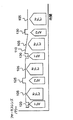
図1は、本発明の一実施形態の方法を使用したフォーカスレンズの光パワーの動作の図を示す。この場合、オートフォーカス画像120(AF1と名称がつけられている)および125(AF2と名称がつけられている)がビデオ画像105(ビデオと名称がつけられている)の捕捉間に捕捉され、ここでオートフォーカス画像は、第1の組120に続いて第2の組125において捕捉される。各オートフォーカス画像の捕捉の前に、フォーカスレンズは、ビデオ捕捉と異なるフォーカス設定に変更される。図1が示すように、第1のオートフォーカス画像の組120は、より低い光パワーのフォーカス設定を有し、かつ、第2のオートフォーカス画像の組125は、より高い光パワーのフォーカス設定を有する。オートフォーカス画像120および125のフォーカス設定と、ビデオ画像105のフォーカス設定との間の変化は、同一の量のデフォーカスだが、オートフォーカス画像を離隔するビデオ画像のフォーカス設定と比較して反対方向のデフォーカスとなるように選択される。
FIG. 1 shows a diagram of the optical power operation of a focus lens using the method of one embodiment of the present invention. In this case, autofocus images 120 (named AF1) and 125 (named AF2) are captured during the capture of video image 105 (named video), Here, the autofocus image is captured in the
簡略化のため、ビデオフレームのフォーカス設定から第1の組のオートフォーカス画像および第2の組のオートフォーカス画像への光パワーの変化が、図1、図4、図5、図6において同一のものとして示されているが、第1の組のオートフォーカス画像および第2の組のオートフォーカス画像において、フォーカスレンズのフォーカシング特性およびレンズアセンブリに基づき、同一の量のデフォーカスを生成する実際の光パワーの変化は異なることがある。オートフォーカス画像120およびオートフォーカス画像125のフォーカス設定は、ビデオ画像105のフォーカス設定を一括にするため、ビデオ画像が十分にフォーカスされている場合、オートフォーカス画像120およびオートフォーカス画像125は等しくデフォーカスされる。結果として、120および125の2つの組のオートフォーカス画像がフォーカス品質において互いに比較されるとき、オートフォーカス画像120および125間に捕捉されたビデオ画像105のフォーカスが合っていると、オートフォーカス画像120およびオートフォーカス画像125の2つの組のフォーカス品質は同一になる。
For simplification, the change in optical power from the focus setting of the video frame to the first set of autofocus images and the second set of autofocus images is the same in FIG. 1, FIG. 4, FIG. 5, and FIG. Although shown as such, in the first set of autofocus images and the second set of autofocus images, the actual light that produces the same amount of defocus based on the focusing characteristics of the focus lens and the lens assembly The change in power can be different. The focus setting of the
逆に、ビデオ画像105が十分にフォーカスされていない場合、オートフォーカス画像の組120またはオートフォーカス画像の組125のうち1つのフォーカス品質が、他方のオートフォーカス画像の組のフォーカス品質よりも良くなる。本発明において、次のビデオ画像105が捕捉される前にフォーカス調整が必要かどうかを決定するために使用されるのは、この、オートフォーカス画像120およびオートフォーカス画像125の2つの組間のフォーカス品質の差である。加えて、オートフォーカス画像120およびオートフォーカス画像125の2つの組間のフォーカス品質の差の度合いが、次のビデオ画像105のフォーカス品質を向上するために適用されるフォーカス調整の量を決定するのに使用される。ビデオフレーム捕捉105のフォーカス調整が必要かどうかの判断は、第1の組のオートフォーカス画像120の1つの組、第2の組のオートフォーカス画像125の1つの組および1つのビデオフレーム105が捕捉された後に、図1に示される工程を使用して行うことが可能である。
Conversely, when the
ビデオフレーム捕捉105にフォーカス調整が必要かどうかを判断した後、フォーカス調整は、光パワー変化110がビデオフレーム捕捉105中に示される図1に示されるように、次のビデオフレーム捕捉105中に実行することが可能である。代わりに、フォーカス調整は、オートフォーカス画像の光パワー変化と併せて実行することが可能である。フォーカス調整110に後続するオートフォーカス画像の組130のフォーカス変化は、フォーカス調整の前と同一の量だが、変化は、目下、直前に捕捉されたビデオ画像105の最後の新しいフォーカス設定と比較されるため、オートフォーカス画像の組130の光パワーは、以前のオートフォーカスの組125と異なる。
After determining whether the
図2は、カメラが、画像が捕捉され、即座に表示されるプレビューモードにあるときに使用される、本発明の方法の一実施形態のフローチャートを示す。工程は、カメラがデフォルトのフォーカス設定の状態で、カメラまたはデジタル捕捉デバイスの電源がオンにされる、200にて開始される。210にて、ビデオフレームが捕捉され、表示部に送られる。220にて、フォーカス設定が、第1の組のオートフォーカス画像の捕捉のために、ある量(例えば1ジオプターまたは、レンズの被写界深度に相当する量、例えばそのフォーカス設定における1フォーカスゾーン)だけ変化する。230にて、第1の組のオートフォーカス画像が捕捉され、一時的に保存される。フォーカスシステムは、次いで、240にて、ビデオフレーム捕捉の設定に戻る。250にて、別のビデオフレームが捕捉され、表示部に送られる。フォーカス設定は、次いで、255にて、第2の組のオートフォーカス画像の捕捉のために、第2の量だけ変化する。 FIG. 2 shows a flowchart of one embodiment of the method of the present invention used when the camera is in a preview mode where images are captured and displayed immediately. The process begins at 200 when the camera or digital capture device is powered on with the camera in the default focus setting. At 210, a video frame is captured and sent to the display. At 220, the focus setting is a certain amount (eg, one diopter or an amount corresponding to the depth of field of the lens, eg, one focus zone at that focus setting) for capturing the first set of autofocus images. Only changes. At 230, a first set of autofocus images is captured and temporarily stored. The focus system then returns to setting up video frame capture at 240. At 250, another video frame is captured and sent to the display. The focus setting is then changed by a second amount at 255 to capture a second set of autofocus images.
第2の組のオートフォーカス画像が、次いで、ステップ260にて捕捉され、一時的に保存される。フォーカスシステムは、次いで、265にて、ビデオフレーム捕捉の設定に戻る。270にて、別のビデオフレームが捕捉され、表示部に送られる。270にて、ビデオフレームを捕捉するが、第1の組のフォーカス品質および第2の組のオートフォーカス画像が評価され、各オートフォーカス画像についてフォーカス値が生成される。一連のオートフォーカス画像を評価してフォーカス値を生成する技術は、当該技術分野において周知であり、技術例が、米国特許第5877809号、米国特許第6441855号、米国特許第6885819号および米国特許出願第2003/0160886号にある。275にて、第1のオートフォーカスの組のフォーカス値および第2のオートフォーカスの組のフォーカス値が、選択された閾値内において同一かどうかに基づき決断がなされる。第1のオートフォーカスの組のフォーカス値と、第2のオートフォーカスの組のフォーカス値との間の差が、選定された閾値よりも小さい場合、工程は220に進む。第1の組のオートフォーカス画像または第2の組のオートフォーカス画像のどちらかのフォーカス値が、他方より高く(より良いフォーカス品質)、かつ、閾値の範囲外の場合、デフォーカス条件が検出され、後続するビデオフレーム捕捉のフォーカス設定が、280にて、より良いフォーカス品質を有するオートフォーカス画像の組のフォーカス設定の側へ調整され、工程は220に進む。
A second set of autofocus images is then captured at
フォーカス設定調整の工程において、検出されたデフォーカス条件を補正するためのフォーカス設定調整の速度が、高速フォーカスシステムのフォーカス特性およびカメラの画像化システムに基づき選択される。フォーカス設定調整の速度は、製造中に実施される較正工程に基づきオートフォーカスシステムにプログラムすることが可能である。代わりに、フォーカス設定調整の速度は、安定して良好なフォーカス品質の度合いを得るのに必要なフォーカス設定調整の数に基づき、使用時に、徐々にオートフォーカスシステムに学ばせることが可能である。 In the focus setting adjustment step, the speed of the focus setting adjustment for correcting the detected defocus condition is selected based on the focus characteristics of the high-speed focus system and the imaging system of the camera. The speed of the focus setting adjustment can be programmed into the autofocus system based on a calibration process performed during manufacture. Instead, the speed of the focus setting adjustment can be gradually learned by the autofocus system during use based on the number of focus setting adjustments necessary to obtain a stable and good degree of focus quality.
バースト捕捉のオートフォーカスの一実施形態における本発明の工程は、ビデオ画像が代わりにバースト画像である図2に示されている工程フローと類似する工程フローに従うことに留意されたい。加えて、バースト画像は表示部に送られる代わりに記憶装置に送られる。 Note that the process of the present invention in one embodiment of burst capture autofocus follows a process flow similar to the process flow shown in FIG. 2 where the video image is instead a burst image. In addition, the burst image is sent to the storage device instead of being sent to the display unit.
プレビューモードにおけるフォーカシングの別の実施形態における本発明の工程は、図2に記載されるように、静止画像の捕捉のためのフォーカシングにも適用されることにも留意されたい。この場合、カメラは、静止画像の捕捉の前にプレビューモードに設定され、かつ、カメラ自体も、光景の内容が変化するにつれて、プレビューモードにてフォーカスを継続する。カメラは、操作者が捕捉ボタンを押すときにはすでにフォーカスされており、それによってカメラに静止画像の捕捉を指示する。 It should also be noted that the inventive process in another embodiment of focusing in preview mode also applies to focusing for still image capture, as described in FIG. In this case, the camera is set to the preview mode before capturing the still image, and the camera itself continues to focus in the preview mode as the scene content changes. The camera is already focused when the operator presses the capture button, thereby instructing the camera to capture a still image.
図3は、進行中の連続的なビデオ捕捉についての本発明の方法の別の実施形態のフローチャートを示す。工程は、300に示すように、ビデオモードにてすでに動作中のカメラにて開始される。310にて、フォーカス設定は、第1の組のオートフォーカス画像の捕捉の量だけ変化する。第1の組のオートフォーカス画像は、次いで、320にて捕捉され、一時的に保存される。フォーカスシステムは、次いで、330にて、ビデオフレーム捕捉の設定に戻る。340にて、ビデオフレームは捕捉され、保存され、一般に表示部に送られる。だが、ビデオフレームの表示部への送信は、本発明には必要ない。350にて、第1の組のオートフォーカス画像のフォーカス値および第2の組のオートフォーカス画像のフォーカス値を通じて決定される、相対的なフォーカス品質が、決定される。次いで、360にて、第1の組のオートフォーカス画像および第2の組のオートフォーカス画像が、閾値内にて、同一のフォーカス値(相対的なフォーカス品質)を有するかどうかに基づき決断がなされる。第1の組のオートフォーカス画像および第2の組のオートフォーカス画像の相対的なフォーカス品質が選択された閾値内の場合、工程は370に続く。370にて、フォーカス設定は、第2の組のオートフォーカス画像の捕捉の量だけ変化する。第2の組のオートフォーカス画像は375にて捕捉される。フォーカスシステムは、次いで、380にて、ビデオフレーム捕捉のフォーカス設定に戻る。385にて、ビデオフレームが捕捉され、保存され、一般に表示部に送られる。 FIG. 3 shows a flowchart of another embodiment of the method of the present invention for ongoing video capture in progress. The process begins with a camera already operating in video mode, as shown at 300. At 310, the focus setting changes by the amount of capture of the first set of autofocus images. The first set of autofocus images is then captured at 320 and temporarily stored. The focus system then returns to setting up video frame capture at 330. At 340, the video frame is captured, stored, and generally sent to the display. However, transmission of video frames to the display is not necessary for the present invention. At 350, the relative focus quality determined through the focus value of the first set of autofocus images and the focus value of the second set of autofocus images is determined. A determination is then made at 360 based on whether the first set of autofocus images and the second set of autofocus images have the same focus value (relative focus quality) within a threshold. The If the relative focus quality of the first set of autofocus images and the second set of autofocus images is within the selected threshold, the process continues to 370. At 370, the focus setting changes by the amount of capture of the second set of autofocus images. A second set of autofocus images is captured at 375. The focus system then returns at 380 to the video frame capture focus setting. At 385, the video frame is captured, stored, and generally sent to the display.
相対的なフォーカス品質は、390にて、第1の組のオートフォーカス画像の最後の組の決定されたフォーカス値および第2の組のオートフォーカス画像の最後の組の決定されたフォーカス値を通じて評価される。392にて、第1の組のオートフォーカス画像の最後の組および第2の組のオートフォーカス画像の最後の組が、選択された閾値内にて同一のフォーカス値(相対的なフォーカス品質)を有するかどうかに基づき、工程の方向の決断を得る。第1の組のオートフォーカス画像の最後の組および第2の組のオートフォーカス画像の最後の組が選択された閾値内にて同一のフォーカス値を有する場合、工程はステップ310に戻る。第1の組のオートフォーカス画像または第2の組のオートフォーカス画像のどちらかが、より高いフォーカス値(より良い相対的なフォーカス品質)を有し、選択された閾値を超える場合、工程は395に進む。395にて、ビデオフレーム捕捉のフォーカスシステム設定は、より良いフォーカス品質を有するオートフォーカス画像の組のフォーカス設定の側へ調整され、工程は310に戻る。 Relative focus quality is evaluated at 390 through the last set of determined focus values of the first set of autofocus images and the last set of determined focus values of the second set of autofocus images. Is done. At 392, the last set of the first set of autofocus images and the last set of the second set of autofocus images have the same focus value (relative focus quality) within the selected threshold. Get a process direction decision based on whether you have one. If the last set of the first set of autofocus images and the last set of the second set of autofocus images have the same focus value within the selected threshold, the process returns to step 310. If either the first set of autofocus images or the second set of autofocus images has a higher focus value (better relative focus quality) and exceeds the selected threshold, the process is 395. Proceed to At 395, the focus system setting for video frame capture is adjusted to the focus setting side of the set of autofocus images having better focus quality, and the process returns to 310.
360にて、第1のオートフォーカス画像の組または第2のオートフォーカス画像の組のどちらかの相対的なフォーカス品質が、閾値を超えるより高いフォーカス値(より良いフォーカス品質)を有することが決定した場合は、工程はステップ365に進む。365にて、フォーカスシステム設定は、より良いフォーカス品質を生成したオートフォーカス画像の組のフォーカス設定の側へ調整され、前述のように、工程は370に進む。 At 360, it is determined that the relative focus quality of either the first autofocus image set or the second autofocus image set has a higher focus value (better focus quality) that exceeds a threshold. If so, the process proceeds to step 365. At 365, the focus system setting is adjusted to the focus setting side of the set of autofocus images that produced better focus quality, and the process proceeds to 370 as described above.
図4は、複数のオートフォーカス画像が第1の組のオートフォーカス画像および第2の組のオートフォーカス画像の両方に含まれる、本発明の方法の別の実施形態の図を示す。この実施形態において、第1の組のオートフォーカス画像420(AF1と名称がつけられている)は、光パワーを減少するステップを伴う複数の画像を含み、第2の組のオートフォーカス画像425(AF2と名称がつけられている)は、光パワーを増加するステップを伴う複数の画像を含む。この実施形態は、第1の組のオートフォーカス画像420の1つの組、第2の組のオートフォーカス画像425の1つの組および1つのビデオフレーム405が捕捉された後、ビデオフレーム405(ビデオと名称がつけられている)の捕捉にフォーカス調整が必要かどうかについて決断することを可能にする。加えて、第1の組のオートフォーカス画像420および第2の組のオートフォーカス画像425内に異なるフォーカス設定を有する複数のオートフォーカス画像が捕捉されるため、生成されるフォーカス値(相対的フォーカス品質)の測定は正確性が増す。
FIG. 4 shows a diagram of another embodiment of the method of the present invention in which multiple autofocus images are included in both the first set of autofocus images and the second set of autofocus images. In this embodiment, a first set of autofocus images 420 (named AF1) includes a plurality of images with steps to reduce optical power, and a second set of autofocus images 425 ( AF2) includes a plurality of images with steps to increase the optical power. This embodiment includes a video frame 405 (video and video) after one set of first set of
図5は、オートフォーカス画像の光パワーの変化の量が組毎に変化する、本発明の方法のさらに別の実施形態の図を示す。この場合、第1の組のオートフォーカス画像520およびオートフォーカス画像521(AF1と名称がつけられている)の2つの組ならびに第2の組のオートフォーカス画像525およびオートフォーカス画像526(AF2と名称がつけられている)の2つの組ならびに2つのビデオフレーム505(ビデオと名称がつけられている)が捕捉される後まで、フォーカス品質の決断に達しない。ビデオフレーム捕捉のフォーカス調整を行う必要は、次いで、第1の組のオートフォーカス画像520およびオートフォーカス画像521の2つの組の相対的なフォーカス品質と、第2の組のオートフォーカス画像525およびオートフォーカス画像526の2つの組を比較することによって決定される。この実施形態ではさらに離焦ビデオフレームを生成するが、第1の(520および521)組のオートフォーカス画像および第2の(525および526)組のオートフォーカス画像が、各ビデオ捕捉間に1つのオートフォーカス画像のみを捕捉するため、オートフォーカス画像内のノイズを軽減するために各オートフォーカス画像の露光時間を長くすることができ、さらに、ビデオフレーム捕捉にフォーカス調整が必要かどうかを決定するために、複数のオートフォーカス画像が評価され、したがって、より高いフォーカスの正確性が得られる。
FIG. 5 shows a diagram of yet another embodiment of the method of the present invention in which the amount of change in optical power of the autofocus image varies from set to set. In this case, two sets of the first set of
図6に、第1の組のオートフォーカス画像620(AF1と名称がつけられている)および第2の組のオートフォーカス画像625(AF2と名称がつけられている)が同一で、かつ、それぞれが光パワーを減少するステップおよび増加するステップを含む、本発明の方法のさらに別の実施形態の図を示す。図6の図は、1つの減少するステップおよび1つの増加するステップを示すが、オートフォーカス画像620またはオートフォーカス画像625の各組における、減少するステップおよび増加するステップの数は、それぞれにおいておそらく1つより多い。この実施形態において、ビデオフレーム605(ビデオと名称がつけられている)の捕捉にフォーカス調整が必要かどうかについての決断は、オートフォーカス画像620またはオートフォーカス画像625の1つの組が捕捉された後に達することが可能である。フォーカス調整は、次いで、後続のビデオフレーム605の捕捉中に実施可能である。このアプローチは、生成される離焦ビデオフレーム605の数をさらに低減する。なぜならデフォーカス条件がより高速に検出されるからである。
In FIG. 6, the first set of autofocus images 620 (named AF1) and the second set of autofocus images 625 (named AF2) are identical and each FIG. 6 shows a diagram of yet another embodiment of the method of the present invention, including steps of decreasing and increasing optical power. The diagram of FIG. 6 shows one decreasing step and one increasing step, but the number of decreasing and increasing steps in each set of
静止画像の捕捉前のフォーカスの検証のために、図6に示す工程に類似する工程を使用するフォーカス評価が可能であることに留意されたい。この場合、図2のフローチャートに記載されるように、カメラ自体をプレビューモードにフォーカスし、次いで、操作者が捕捉ボタンを押してカメラに静止画像を捕捉するよう指示すると、フォーカス品質の最終評価が、フォーカスレンズの増加および減少する光パワーとともに、いくつかのオートフォーカス画像を捕捉することによって達成されうる。オートフォーカス画像は、次いで、相対的なフォーカス品質について評価され、かつ、静止画像の捕捉前に最終フォーカス調整が必要かどうかについて決断がなされる。 Note that focus evaluation using a process similar to that shown in FIG. 6 is possible for verification of focus prior to still image capture. In this case, as described in the flowchart of FIG. 2, when the camera itself is focused on the preview mode, and then the operator presses the capture button to instruct the camera to capture a still image, the final evaluation of the focus quality is It can be achieved by capturing several autofocus images with increasing and decreasing optical power of the focus lens. The autofocus image is then evaluated for relative focus quality and a determination is made as to whether final focus adjustment is required before capturing the still image.
本発明のまたさらに別の実施形態において、前述の方法を支持するため、短い露光時間およびオートフォーカス画像の迅速な読み出しを提供するフォーカスシステムが開示される。図7は、本発明の特徴を含む画像捕捉デバイスの図を示す。本発明は、異なるタイプのオートフォーカス画像の迅速な捕捉を含む。オートフォーカス画像の迅速な捕捉には、短い露光時間およびイメージセンサからの高速読み出しが必要である。したがって、本発明のフォーカスシステムは、光パワーの迅速な変化が可能なフォーカスレンズ720を含むレンズアセンブリ700を含み、例示として、1ジオプターの変化は0.01秒またはそれより短い。フォーカスレンズ720は、開口停止部710の背後に配置されることが示されるが、それはその位置が、一般に、画像捕捉デバイスの全体の長さが最短になる位置だからである。本発明の範囲内で、光が入射するレンズの端部などの、フォーカスレンズ720または開口停止部710の他の位置が可能である。
In yet another embodiment of the present invention, a focus system is disclosed that provides a short exposure time and rapid readout of an autofocus image to support the foregoing method. FIG. 7 shows a diagram of an image capture device that includes features of the present invention. The present invention includes the rapid capture of different types of autofocus images. To capture an autofocus image quickly, a short exposure time and high-speed readout from an image sensor are required. Accordingly, the focus system of the present invention includes a
その内容全体を本願に引用して援用する、2005年7月28日出願の「Image Sensor with Improved Light Sensitivity」という名称の米国特許出願2007/0024931号に記載されるように、イメージセンサ730による集光の効率を上げるため、可視光スペクトル全域にわたって光を集めるパンクロマティック画素を有するイメージセンサが使用される。より高い光感度およびより高速の捕捉時間のため、オートフォーカス画像は、サブサンプル方式で読み出しされたパンクロマティック画素のみを含むことが可能である。加えて、センサは、各画像において読み出しされる画素数を低減するため、センサの一部の読み出しを可能にすべきである。これにより、オートフォーカス画像は、映し出される光景内の顔または同定される対象物などの検出した関心領域を含むことが可能である。センサはまた、画素のビニングされた読み出しを可能にすべきである。ビニングは隣り合う画素を電気的にともに連結することによって行われ、ビニングされた画素間で蓄積された電荷が共有され、それによって有効な画素のサイズが増え、かつ、光に対する画素の感度が上がる。
A collection by
図8を参照すると、デジタル静止カメラ、ビデオカメラ等などの画像捕捉デバイス800の簡易ブロック図を示している。カメラ800は、レンズ700などのフォーカスレンズシステムを含む。当該技術分野において周知であるCMOSまたはCCDイメージセンサの形態をとることが可能なセンサ、例えば本発明においてはイメージセンサ730を利用することができる。オートフォーカスシステム806は、前述のようなフォーカス評価を実行可能なフォーカス評価のセクション/回路および前述のようなフォーカス調整を実行するフォーカス調整のセクション/回路を含む。セクション808およびセクション810は、意図した設計要件によって、ハードウェア、ソフトウェアまたは両方の組合せを包含可能である。
Referring to FIG. 8, a simplified block diagram of an
カメラ800のコントローラとしての役割を果たすプロセッサ812は、多数のマイクロプロセッサ、マイクロコントローラ、デジタル信号プロセッサ等のうちのいかなるものでも包含することが可能である。一実施形態におけるコントローラ812は、オートフォーカスシステム806と協働し、上述のオートフォーカス技術のすべてを実行する。揮発性および不揮発性メモリの両方を含むことが可能なメモリ814は、データはもとより、カメラ800を操作するのに使用される必要なプログラムも保存する。当該技術分野において周知のように、液晶ディスプレイ(LCD)816を包含可能な表示部816は、現在捕捉されている画像はもとより、以前捕捉された画像も提示することが可能である。
The
本発明は、その特定の好ましい実施形態を参照して詳述されたが、本発明の範囲および精神の中で変更および変形を施すことが可能であることが理解されるであろう。 Although the invention has been described in detail with reference to certain preferred embodiments thereof, it will be understood that variations and modifications can be effected within the scope and spirit of the invention.
105 ビデオフレーム、 110 ビデオフレーム中のフォーカス調整、 120 第1の組のオートフォーカス画像のオートフォーカス画像、 125 第2の組のオートフォーカス画像のオートフォーカス画像、 130 第1の組のオートフォーカス画像の、ビデオ捕捉のフォーカス調整後のオートフォーカス画像、 200 工程ブロック、 210 工程ブロック、 220 工程ブロック、 230 工程ブロック、 240 工程ブロック、 250 工程ブロック、 255 工程ブロック、 260 工程ブロック、 265 工程ブロック、 270 工程ブロック、 275 工程ブロック、 280 工程ブロック、 300 工程ブロック、 310 工程ブロック、 320 工程ブロック、 330 工程ブロック、 340 工程ブロック、 350 工程ブロック、 360 工程ブロック、 365 工程ブロック、 370 工程ブロック、 375 工程ブロック、 380 工程ブロック、 385 工程ブロック、 390 工程ブロック、 392 工程ブロック、 395 工程ブロック、 405 ビデオフレーム、 420 第1の組のオートフォーカス画像のオートフォーカス画像、 425 第2の組のオートフォーカス画像のオートフォーカス画像、 505 ビデオフレーム、 520 第1の組のオートフォーカス画像の第1のオートフォーカス画像、 521 第1の組のオートフォーカス画像の第2のオートフォーカス画像、 525 第2の組のオートフォーカス画像の第1のオートフォーカス画像、 526 第2の組のオートフォーカス画像の第2のオートフォーカス画像、 605 ビデオフレーム、 620 第1の組のオートフォーカス画像のオートフォーカス画像、 625 第2の組のオートフォーカス画像のオートフォーカス画像、 700 レンズアセンブリ、 710 開口停止部、 720 フォーカスレンズ、 730 イメージセンサ、 800 画像捕捉デバイス、 802 レンズ、 804 センサ、 806 オートフォーカスセクション、 808 フォーカス評価セクション、 810 フォーカス調整セクション、 812 プロセッサ、 814 メモリ、 816 表示部。 105 video frames, 110 focus adjustments in video frames, 120 autofocus images of a first set of autofocus images, 125 autofocus images of a second set of autofocus images, 130 130 autofocus images of a first set , Autofocus image after video capture focus adjustment, 200 process block, 210 process block, 220 process block, 230 process block, 240 process block, 250 process block, 255 process block, 260 process block, 265 process block, 270 process Block, 275 process block, 280 process block, 300 process block, 310 process block, 320 process block, 330 process block, 340 process block 350 process block, 360 process block, 365 process block, 370 process block, 375 process block, 380 process block, 385 process block, 390 process block, 392 process block, 395 process block, 405 video frame, 420 first frame An autofocus image of a set of autofocus images, 425 an autofocus image of a second set of autofocus images, 505 video frames, 520 a first autofocus image of an autofocus image of the first set, 521 a first set of A second autofocus image of the second autofocus image, 525 a first autofocus image of the second set of autofocus images, and 526 a second autofocus image of the second set of autofocus images. Focus image, 605 video frame, 620 autofocus image of first set autofocus image, 625 autofocus image of second set autofocus image, 700 lens assembly, 710 aperture stop, 720 focus lens, 730 image Sensor, 800 image capture device, 802 lens, 804 sensor, 806 autofocus section, 808 focus evaluation section, 810 focus adjustment section, 812 processor, 814 memory, 816 display.
Claims (2)
第1オートフォーカス画像、第1ビデオ画像、第2オートフォーカス画像の順に画像を補足してから、第1ビデオ画像よりも後に補足される第2ビデオ画像のためのフォーカス設定を調整するにあたり、
第1フォーカス設定で第1オートフォーカス画像を捕捉し、
前記第1オートフォーカス画像を捕捉した後に、第2フォーカス設定で第1ビデオ画像を捕捉し、
前記第1ビデオ画像を捕捉した後に、第3フォーカス設定で第2オートフォーカス画像を捕捉し、
前記第2フォーカス設定におけるフォーカスレンズパワーは、前記第1フォーカス設定と前記第3フォーカス設定の間のフォーカスレンズパワーであり、
前記第1オートフォーカス画像と前記第2オートフォーカス画像の間におけるフォーカス品質の差に基づいて、第2ビデオ画像のための第4フォーカス設定を調整し、
前記調整された第4フォーカス設定を利用して第2ビデオ画像を捕捉する、
ことを特徴とする方法。 A method of autofocusing an image capture device capable of capturing multiple images with different focus settings,
In adjusting the focus setting for the second video image supplemented after the first video image after supplementing the images in the order of the first autofocus image, the first video image, and the second autofocus image,
Capture the first autofocus image with the first focus setting,
After capturing the first autofocus image, capture the first video image with the second focus setting;
After capturing the first video image, capturing a second autofocus image with a third focus setting;
Focus lens power in the second focus setting is a focus lens power between the first focus setting and the third focus setting,
Adjusting a fourth focus setting for a second video image based on a difference in focus quality between the first autofocus image and the second autofocus image;
Capturing a second video image using the adjusted fourth focus setting;
A method characterized by that.
レンズと、
前記レンズの光路内に位置する画像センサと、
前記レンズのフォーカスを調整するために前記レンズに連結されるオートフォーカスシステムと、
を含み、
前記オートフォーカスシステムは、
第1フォーカス設定で第1オートフォーカス画像を捕捉し、
前記第1オートフォーカス画像を捕捉した後に、第2フォーカス設定で第1ビデオ画像を捕捉し、
前記第1ビデオ画像を捕捉した後に、第3フォーカス設定で第2オートフォーカス画像を捕捉し、
前記第2フォーカス設定におけるレンズパワーは、前記第1フォーカス設定と前記第3フォーカス設定の間のレンズパワーであり、
前記オートフォーカスシステムは、さらに、
第1オートフォーカス画像、第1ビデオ画像、第2オートフォーカス画像の順に捕捉される画像のうち、第1オートフォーカス画像と第2オートフォーカス画像のフォーカス品質の差を評価することに使用されるフォーカス評価セクションと、
前記第1オートフォーカス画像と前記第2オートフォーカス画像を捕捉するにあたって、前記第1オートフォーカス画像と前記第2オートフォーカス画像に関するフォーカス設定が、前記第1ビデオ画像に関するフォーカス設定と異なるように、前記レンズのフォーカスを調整し、当該第1ビデオ画像よりも後に補足される第2ビデオ画像の捕捉のための第4フォーカス設定を、前記第1オートフォーカス画像と前記第2オートフォーカス画像の間のフォーカス品質の差に基づいて調整するフォーカス調整セクションと、
を含む、
ことを特徴とする画像捕捉デバイス。
An image capture device that captures video images and autofocus images,
A lens,
An image sensor located in the optical path of the lens;
An autofocus system coupled to the lens to adjust the focus of the lens;
Including
The autofocus system is
Capture the first autofocus image with the first focus setting,
After capturing the first autofocus image, capture the first video image with the second focus setting;
After capturing the first video image, capturing a second autofocus image with a third focus setting;
Lens power in the second focus setting is a lens power between the first focus setting and the third focus setting,
The autofocus system further includes:
Focus used to evaluate the difference in focus quality between the first autofocus image and the second autofocus image among images captured in the order of the first autofocus image, the first video image, and the second autofocus image. An evaluation section;
In capturing the first autofocus image and the second autofocus image, the focus setting for the first autofocus image and the second autofocus image is different from the focus setting for the first video image. Adjusting the focus of the lens and setting a fourth focus setting for capturing a second video image supplemented after the first video image is a focus between the first autofocus image and the second autofocus image. A focus adjustment section that adjusts based on quality differences,
including,
An image capturing device characterized by that.
Applications Claiming Priority (3)
| Application Number | Priority Date | Filing Date | Title |
|---|---|---|---|
| US12/250,589 US8164682B2 (en) | 2008-10-14 | 2008-10-14 | Dithered focus evaluation |
| US12/250,589 | 2008-10-14 | ||
| PCT/US2009/005533 WO2010044831A1 (en) | 2008-10-14 | 2009-10-09 | Dithered focus evaluation |
Publications (3)
| Publication Number | Publication Date |
|---|---|
| JP2012506066A JP2012506066A (en) | 2012-03-08 |
| JP2012506066A5 JP2012506066A5 (en) | 2012-09-20 |
| JP5745416B2 true JP5745416B2 (en) | 2015-07-08 |
Family
ID=41323379
Family Applications (1)
| Application Number | Title | Priority Date | Filing Date |
|---|---|---|---|
| JP2011532073A Active JP5745416B2 (en) | 2008-10-14 | 2009-10-09 | Dither focus evaluation |
Country Status (5)
| Country | Link |
|---|---|
| US (1) | US8164682B2 (en) |
| EP (1) | EP2335404B1 (en) |
| JP (1) | JP5745416B2 (en) |
| CN (1) | CN102172013B (en) |
| WO (1) | WO2010044831A1 (en) |
Families Citing this family (24)
| Publication number | Priority date | Publication date | Assignee | Title |
|---|---|---|---|---|
| US8139130B2 (en) | 2005-07-28 | 2012-03-20 | Omnivision Technologies, Inc. | Image sensor with improved light sensitivity |
| US8274715B2 (en) | 2005-07-28 | 2012-09-25 | Omnivision Technologies, Inc. | Processing color and panchromatic pixels |
| US7916362B2 (en) | 2006-05-22 | 2011-03-29 | Eastman Kodak Company | Image sensor with improved light sensitivity |
| US8031258B2 (en) | 2006-10-04 | 2011-10-04 | Omnivision Technologies, Inc. | Providing multiple video signals from single sensor |
| US8224082B2 (en) * | 2009-03-10 | 2012-07-17 | Omnivision Technologies, Inc. | CFA image with synthetic panchromatic image |
| US8068153B2 (en) * | 2009-03-27 | 2011-11-29 | Omnivision Technologies, Inc. | Producing full-color image using CFA image |
| US8045024B2 (en) * | 2009-04-15 | 2011-10-25 | Omnivision Technologies, Inc. | Producing full-color image with reduced motion blur |
| US8203633B2 (en) * | 2009-05-27 | 2012-06-19 | Omnivision Technologies, Inc. | Four-channel color filter array pattern |
| US8237831B2 (en) * | 2009-05-28 | 2012-08-07 | Omnivision Technologies, Inc. | Four-channel color filter array interpolation |
| US8125546B2 (en) * | 2009-06-05 | 2012-02-28 | Omnivision Technologies, Inc. | Color filter array pattern having four-channels |
| US8253832B2 (en) * | 2009-06-09 | 2012-08-28 | Omnivision Technologies, Inc. | Interpolation for four-channel color filter array |
| US8964103B2 (en) * | 2010-02-16 | 2015-02-24 | Blackberry Limited | Method and apparatus for reducing continuous autofocus power consumption |
| US9118842B2 (en) | 2010-09-16 | 2015-08-25 | Intellectual Ventures Fund 83 Llc | Producing focused videos from single captured video |
| DE102011121928B4 (en) * | 2011-08-01 | 2015-03-05 | Physik Instrumente (Pi) Gmbh & Co. Kg | Arrangement for operating a dynamic nanofocusing system |
| CN103297665A (en) * | 2012-02-22 | 2013-09-11 | 庄佑华 | Image acquisition system |
| CN103475818A (en) * | 2013-09-03 | 2013-12-25 | 小米科技有限责任公司 | Shooting method and device and terminal device |
| CN104717418A (en) * | 2013-12-16 | 2015-06-17 | 腾讯科技(深圳)有限公司 | Focusing method, device and electronic equipment |
| US9575221B2 (en) | 2013-12-31 | 2017-02-21 | Cognex Corporation | Systems and methods reduce temperature induced drift effects on a liquid lens |
| US10690816B2 (en) | 2013-12-31 | 2020-06-23 | Cognex Corporation | Systems and methods reduce temperature induced drift effects on a liquid lens |
| CN103780840B (en) * | 2014-01-21 | 2016-06-08 | 上海果壳电子有限公司 | Two camera shooting image forming apparatus of a kind of high-quality imaging and method thereof |
| CN103763477B (en) * | 2014-02-21 | 2016-06-08 | 上海果壳电子有限公司 | A kind of dual camera claps back focusing imaging device and method |
| CN105426848B (en) * | 2014-11-03 | 2020-12-18 | 苏州思源科安信息技术有限公司 | Imaging method for improving success rate of biological recognition |
| CN105120153B (en) * | 2015-08-20 | 2018-01-19 | 广东欧珀移动通信有限公司 | A kind of image capturing method and device |
| CN114584700B (en) * | 2020-11-30 | 2024-04-05 | 京东方科技集团股份有限公司 | Focusing marking method, marking device and electronic equipment |
Family Cites Families (27)
| Publication number | Priority date | Publication date | Assignee | Title |
|---|---|---|---|---|
| JPS6020111A (en) * | 1983-07-14 | 1985-02-01 | Fuji Electric Corp Res & Dev Ltd | Distance measuring device |
| JP3943613B2 (en) * | 1995-10-02 | 2007-07-11 | キヤノン株式会社 | Imaging device and lens unit |
| JP3752510B2 (en) * | 1996-04-15 | 2006-03-08 | イーストマン コダック カンパニー | Automatic subject detection method for images |
| JP3726630B2 (en) * | 2000-03-27 | 2005-12-14 | コニカミノルタフォトイメージング株式会社 | Digital still camera |
| US6453124B2 (en) * | 2000-03-27 | 2002-09-17 | Minolta Co., Ltd. | Digital camera |
| US6441855B1 (en) * | 2000-05-09 | 2002-08-27 | Eastman Kodak Company | Focusing device |
| JP4355847B2 (en) * | 2000-09-04 | 2009-11-04 | 富士フイルム株式会社 | Camera focus information display apparatus and method |
| JP3992992B2 (en) * | 2002-02-19 | 2007-10-17 | 株式会社リコー | Subject image acquisition device |
| JP4198449B2 (en) * | 2002-02-22 | 2008-12-17 | 富士フイルム株式会社 | Digital camera |
| JP3823921B2 (en) * | 2002-12-27 | 2006-09-20 | コニカミノルタフォトイメージング株式会社 | Imaging device |
| JP4581417B2 (en) * | 2004-01-16 | 2010-11-17 | ソニー株式会社 | Autofocus control device and method, recording medium, and program |
| JP4023457B2 (en) * | 2004-03-02 | 2007-12-19 | ソニー株式会社 | Autofocus control device and method, recording medium, and program |
| JP4649128B2 (en) * | 2004-06-15 | 2011-03-09 | キヤノン株式会社 | Automatic focus adjustment apparatus and imaging apparatus having the automatic focus apparatus |
| EP1821128B1 (en) | 2004-11-16 | 2011-03-16 | Citizen Holdings Co., Ltd. | Automatic focusing apparatus |
| IL174531A0 (en) | 2005-04-06 | 2006-08-20 | Given Imaging Ltd | System and method for performing capsule endoscopy diagnosis in remote sites |
| US8430809B2 (en) * | 2005-08-01 | 2013-04-30 | G. I View Ltd. | Capsule for use in small intestine |
| JP2007086596A (en) * | 2005-09-26 | 2007-04-05 | Pentax Corp | Camera |
| WO2007051147A2 (en) | 2005-10-26 | 2007-05-03 | Capso Vision, Inc. | Onboard data storage and method |
| JP2007150643A (en) * | 2005-11-28 | 2007-06-14 | Sony Corp | Solid state imaging element, driving method therefor, and imaging apparatus |
| US7561789B2 (en) * | 2006-06-29 | 2009-07-14 | Eastman Kodak Company | Autofocusing still and video images |
| JP2008051871A (en) * | 2006-08-22 | 2008-03-06 | Nikon Corp | Automatic focusing device |
| US7769229B2 (en) | 2006-11-30 | 2010-08-03 | Eastman Kodak Company | Processing images having color and panchromatic pixels |
| US8095000B2 (en) * | 2007-02-15 | 2012-01-10 | Panasonic Corporation | Camera system |
| US7729602B2 (en) * | 2007-03-09 | 2010-06-01 | Eastman Kodak Company | Camera using multiple lenses and image sensors operable in a default imaging mode |
| US7676146B2 (en) * | 2007-03-09 | 2010-03-09 | Eastman Kodak Company | Camera using multiple lenses and image sensors to provide improved focusing capability |
| DE102007017267A1 (en) * | 2007-04-12 | 2008-10-16 | Siemens Ag | Method for improving the profitability of examinations or treatments with endoscopic capsules |
| US7667169B2 (en) * | 2008-05-22 | 2010-02-23 | Omnivision Technologies, Inc. | Image sensor with simultaneous auto-focus and image preview |
-
2008
- 2008-10-14 US US12/250,589 patent/US8164682B2/en active Active
-
2009
- 2009-10-09 CN CN200980139432.8A patent/CN102172013B/en active Active
- 2009-10-09 WO PCT/US2009/005533 patent/WO2010044831A1/en active Application Filing
- 2009-10-09 EP EP09740550.0A patent/EP2335404B1/en active Active
- 2009-10-09 JP JP2011532073A patent/JP5745416B2/en active Active
Also Published As
| Publication number | Publication date |
|---|---|
| EP2335404B1 (en) | 2016-10-05 |
| US20100091169A1 (en) | 2010-04-15 |
| WO2010044831A1 (en) | 2010-04-22 |
| CN102172013B (en) | 2014-09-10 |
| US8164682B2 (en) | 2012-04-24 |
| CN102172013A (en) | 2011-08-31 |
| JP2012506066A (en) | 2012-03-08 |
| EP2335404A1 (en) | 2011-06-22 |
Similar Documents
| Publication | Publication Date | Title |
|---|---|---|
| JP5745416B2 (en) | Dither focus evaluation | |
| US8531583B2 (en) | Image capturing apparatus and image processing method | |
| US7546030B2 (en) | Autofocus device and method | |
| US7602435B2 (en) | Image-taking apparatus and focus control program for image-taking apparatus | |
| US20140002606A1 (en) | Enhanced image processing with lens motion | |
| JP5618712B2 (en) | Automatic focusing device and imaging device | |
| JP2004240054A (en) | Camera | |
| US20140204241A1 (en) | Imaging Apparatus | |
| US9967451B2 (en) | Imaging apparatus and imaging method that determine whether an object exists in a refocusable range on the basis of distance information and pupil division of photoelectric converters | |
| WO2013054527A1 (en) | Image capture device, semiconductor integrated circuit, and image capture method | |
| EP2166408B1 (en) | Imaging device and imaging method using the same | |
| US10536624B2 (en) | Image pickup apparatus and image pickup method | |
| JP2018101055A (en) | Focus adjustment device, imaging device and focus adjustment method | |
| US20170034425A1 (en) | Image pickup apparatus and control method therefor | |
| CN102833484A (en) | Image pickup apparatus and control method thereof | |
| JP2007079204A (en) | Auto-focusing device, camera, and lens barrel | |
| JP5217942B2 (en) | Focus adjustment device and imaging device | |
| JP5947489B2 (en) | Focus adjustment device and focus adjustment method | |
| JP2009109792A (en) | Autofocusing device and camera using it | |
| JP5439971B2 (en) | Photometric device and imaging device | |
| JP2004120582A (en) | Camera | |
| JP6191131B2 (en) | Imaging device | |
| JP6005955B2 (en) | Photometric device and imaging device | |
| KR20110027120A (en) | Image pickup apparatus | |
| JP5245644B2 (en) | Exposure calculator |
Legal Events
| Date | Code | Title | Description |
|---|---|---|---|
| A521 | Request for written amendment filed |
Free format text: JAPANESE INTERMEDIATE CODE: A523 Effective date: 20120803 |
|
| A621 | Written request for application examination |
Free format text: JAPANESE INTERMEDIATE CODE: A621 Effective date: 20120803 |
|
| A977 | Report on retrieval |
Free format text: JAPANESE INTERMEDIATE CODE: A971007 Effective date: 20131030 |
|
| A521 | Request for written amendment filed |
Free format text: JAPANESE INTERMEDIATE CODE: A523 Effective date: 20140205 |
|
| A131 | Notification of reasons for refusal |
Free format text: JAPANESE INTERMEDIATE CODE: A131 Effective date: 20140422 |
|
| A521 | Request for written amendment filed |
Free format text: JAPANESE INTERMEDIATE CODE: A523 Effective date: 20140717 |
|
| A131 | Notification of reasons for refusal |
Free format text: JAPANESE INTERMEDIATE CODE: A131 Effective date: 20140819 |
|
| A521 | Request for written amendment filed |
Free format text: JAPANESE INTERMEDIATE CODE: A523 Effective date: 20141113 |
|
| TRDD | Decision of grant or rejection written | ||
| A01 | Written decision to grant a patent or to grant a registration (utility model) |
Free format text: JAPANESE INTERMEDIATE CODE: A01 Effective date: 20150414 |
|
| A61 | First payment of annual fees (during grant procedure) |
Free format text: JAPANESE INTERMEDIATE CODE: A61 Effective date: 20150501 |
|
| R150 | Certificate of patent or registration of utility model |
Ref document number: 5745416 Country of ref document: JP Free format text: JAPANESE INTERMEDIATE CODE: R150 |
|
| R250 | Receipt of annual fees |
Free format text: JAPANESE INTERMEDIATE CODE: R250 |
|
| R250 | Receipt of annual fees |
Free format text: JAPANESE INTERMEDIATE CODE: R250 |
|
| R250 | Receipt of annual fees |
Free format text: JAPANESE INTERMEDIATE CODE: R250 |
|
| R250 | Receipt of annual fees |
Free format text: JAPANESE INTERMEDIATE CODE: R250 |
|
| R250 | Receipt of annual fees |
Free format text: JAPANESE INTERMEDIATE CODE: R250 |
|
| R250 | Receipt of annual fees |
Free format text: JAPANESE INTERMEDIATE CODE: R250 |