EP2335404B1 - Dithered focus evaluation - Google Patents
Dithered focus evaluation Download PDFInfo
- Publication number
- EP2335404B1 EP2335404B1 EP09740550.0A EP09740550A EP2335404B1 EP 2335404 B1 EP2335404 B1 EP 2335404B1 EP 09740550 A EP09740550 A EP 09740550A EP 2335404 B1 EP2335404 B1 EP 2335404B1
- Authority
- EP
- European Patent Office
- Prior art keywords
- focus
- autofocus
- images
- video
- image capture
- Prior art date
- Legal status (The legal status is an assumption and is not a legal conclusion. Google has not performed a legal analysis and makes no representation as to the accuracy of the status listed.)
- Active
Links
- 238000011156 evaluation Methods 0.000 title claims description 14
- 238000000034 method Methods 0.000 claims description 81
- 230000003287 optical effect Effects 0.000 claims description 48
- 230000003247 decreasing effect Effects 0.000 claims description 8
- 230000008569 process Effects 0.000 description 46
- 230000008859 change Effects 0.000 description 12
- 230000009977 dual effect Effects 0.000 description 12
- 230000007423 decrease Effects 0.000 description 3
- 238000000926 separation method Methods 0.000 description 3
- 206010034960 Photophobia Diseases 0.000 description 2
- 235000010724 Wisteria floribunda Nutrition 0.000 description 2
- 238000013459 approach Methods 0.000 description 2
- 238000010586 diagram Methods 0.000 description 2
- 230000007613 environmental effect Effects 0.000 description 2
- 208000013469 light sensitivity Diseases 0.000 description 2
- 239000004973 liquid crystal related substance Substances 0.000 description 2
- 238000005259 measurement Methods 0.000 description 2
- 230000035945 sensitivity Effects 0.000 description 2
- 230000008901 benefit Effects 0.000 description 1
- 230000000903 blocking effect Effects 0.000 description 1
- 238000011088 calibration curve Methods 0.000 description 1
- 230000001413 cellular effect Effects 0.000 description 1
- 238000004891 communication Methods 0.000 description 1
- 238000013461 design Methods 0.000 description 1
- 230000003292 diminished effect Effects 0.000 description 1
- 229920001746 electroactive polymer Polymers 0.000 description 1
- 239000012530 fluid Substances 0.000 description 1
- 238000003384 imaging method Methods 0.000 description 1
- 239000007788 liquid Substances 0.000 description 1
- 238000004519 manufacturing process Methods 0.000 description 1
- 230000009467 reduction Effects 0.000 description 1
- 230000004044 response Effects 0.000 description 1
- 238000001228 spectrum Methods 0.000 description 1
- 238000012795 verification Methods 0.000 description 1
Images


Classifications
-
- H—ELECTRICITY
- H04—ELECTRIC COMMUNICATION TECHNIQUE
- H04N—PICTORIAL COMMUNICATION, e.g. TELEVISION
- H04N23/00—Cameras or camera modules comprising electronic image sensors; Control thereof
- H04N23/60—Control of cameras or camera modules
- H04N23/67—Focus control based on electronic image sensor signals
-
- H—ELECTRICITY
- H04—ELECTRIC COMMUNICATION TECHNIQUE
- H04N—PICTORIAL COMMUNICATION, e.g. TELEVISION
- H04N23/00—Cameras or camera modules comprising electronic image sensors; Control thereof
- H04N23/60—Control of cameras or camera modules
- H04N23/68—Control of cameras or camera modules for stable pick-up of the scene, e.g. compensating for camera body vibrations
- H04N23/681—Motion detection
- H04N23/6812—Motion detection based on additional sensors, e.g. acceleration sensors
-
- H—ELECTRICITY
- H04—ELECTRIC COMMUNICATION TECHNIQUE
- H04N—PICTORIAL COMMUNICATION, e.g. TELEVISION
- H04N25/00—Circuitry of solid-state image sensors [SSIS]; Control thereof
- H04N25/60—Noise processing, e.g. detecting, correcting, reducing or removing noise
- H04N25/63—Noise processing, e.g. detecting, correcting, reducing or removing noise applied to dark current
-
- H—ELECTRICITY
- H04—ELECTRIC COMMUNICATION TECHNIQUE
- H04N—PICTORIAL COMMUNICATION, e.g. TELEVISION
- H04N25/00—Circuitry of solid-state image sensors [SSIS]; Control thereof
- H04N25/70—SSIS architectures; Circuits associated therewith
- H04N25/76—Addressed sensors, e.g. MOS or CMOS sensors
- H04N25/77—Pixel circuitry, e.g. memories, A/D converters, pixel amplifiers, shared circuits or shared components
Definitions
- the invention pertains to the field of autofocus systems for digital cameras. More specifically the invention pertains to the field of autofocus for image capture devices such as digital cameras that can be used for capturing a series of images for video, burst captures, as well as still images.
- autofocus systems in digital cameras for capturing still images or video, use a "through-the-lens" autofocus system that captures a series of 5-20 or more autofocus images taken with a moveable focus lens in different focusing positions.
- the variable focus lens is adjusted electronically to provide 5-20 or more different focal lengths or optical powers for the autofocus images.
- the 5-20 or more autofocus images are analyzed for contrast to determine the focus lens condition that delivers the image with the highest contrast which is deemed the best focus condition.
- focus values are generated for each autofocus image based on the level of contrast present.
- the focus lens is then returned to the focus condition that produced the autofocus image with the highest contrast (highest focus value), or an interpolated position between two or more of the autofocus images, before a final image is captured and stored.
- This method of autofocusing is known as the "hill climb method" because it generates a sequence of focus values that increase in level until they pass over a peak, i.e., a "hill".
- “Through-the-lens” autofocus systems can be very accurate since they measure focus quality directly from autofocus images captured with the same high quality lens that is used to capture the final image.
- “through the lens” autofocus systems can also be very slow due to the many movements of the focusing lens required and the many autofocus images that must be captured and analyzed. This slowness in time-to-focus contributes to the objectionable delay perceived by the user between the time when the capture button is pressed and the image is actually captured, which is known as shutter lag. It is desired to reduce shutter lag.
- the autofocus images are typically derived from the same series of still images or frames that compose the video segment, consequently, the process of autofocusing causes 5-20 or more out-of-focus frames to be produced in the video each time the scene changes.
- the autofocus system would be faster when capturing video as well as still images, and in the case of video capture, each frame would be focused so that the number of out of focus frames is reduced. This is especially important in enabling images from videos to be printed or used in other fashions.
- Dual lens rangefinder modules can also provide a fast evaluation of focus conditions.
- Rangefinder modules can be purchased from Fuji Electric in several models such as the FM6260W.
- Dual lens rangefinder modules contain two lenses that are separated by a distance along with two matching sensor areas to enable matched pairs of low resolution images to be captured. The matched pairs of low resolution images are then analyzed for correlation between the two images to determine the offset between the two images caused by the separation between the two lenses. The offset information is then used along with the lens separation distance to calculate the distance to the scene by triangulation. The calculated distance to the scene is used to guide the use of the focus lens based on a calibration curve established between the distance to the scene as measured by the dual lens rangefinder module and a series of best focused images as produced by the through the lens autofocus system.
- the response time of the Fuji FM6260W modules is advertised as 0.004 sec in high sensitivity mode, which is well within the 1/30 sec required for video autofocus.
- the accuracy of dual lens rangefinder modules are typically influenced by changes in the environmental conditions such as changes in the temperature and/or humidity. So that typically these dual lens rangefinder modules are not used independently for autofocus in digital cameras but instead are used as a rough focus adjustment that is supplemented by a through the lens contrast based autofocus system.
- the problem with the dual lens rangefinder modules is that the calibration between the dual lens rangefinder module and the focus lens setting is not stable within the normal operating environment for digital cameras.
- the dual lens rangefinder module adds the additional cost to the camera of the dual lens rangefinder module itself.
- a split aperture in the lens system is used to create images that can be interpreted for focus information.
- the split aperture creates two optical paths for the light passing through the lens to create at least two autofocus images at the sensor.
- each of the two optical paths creates a full image without shading but reduced light intensity at the image sensor.
- two optical paths with different perspectives are created. The difference in perspective between the two optical paths causes the autofocus images to be displaced laterally in proportion to the degree of defocus and direction of defocus for an object in the image.
- the focus resolution of the split aperture method as measured by the number of detectable focus zones is limited by the effective separation achieved between the two optical paths that are created which is approximately 40% of the lens aperture.
- the focus accuracy of this technique is diminished due to a lack of focus resolution, this is particularly true for small image capture devices such as are found in compact digital cameras, cellular telephones, laptop computers and other communication devices.
- US2007/0071433 discloses a camera having a contrast detector that successively detects contrast data of an object image that is formed on a light-receiving surface of an image sensor, and a focus detector that successively calculates a difference value between currently detected contrast data and previously detected contrast data, and that detects a focused situation on the basis of the difference value and the detected contrast data.
- the camera further has a focus adjuster that drives a photographing optical system so as continuously to shift an image-formed surface from a given position along an optical axis. While the photographing optical system is driven, the focus detector determines whether the image-formed surface surpasses a focused-position corresponding to a position of the light-receiving surface, on the basis of a decreasing-amount of the difference value.
- an autofocus system which is capable of very fast changes in focus over at least a relatively small portion of the focus range of the focusing system is utilized.
- autofocus images are captured before and after each image in the series wherein the autofocus images have different focus settings than the images in the series.
- the autofocus images are then evaluated for focus quality and the focus quality data is compared between autofocus images to determine whether focus adjustments are needed for the following image in the series.
- Focus adjustments are then carried out as needed based on the focus setting for the autofocus image with better focus quality. In this way, focus evaluations and focus adjustments can be accomplished frame by frame with a greatly reduced number of out-of-focus frames being produced when the focus conditions in the scene change.
- a variety of autofocus image sets are disclosed.
- One example uses alternating single step increases and decreases in optical power of the focus lens for first and second sets of autofocus images on either side of the capture of an image in the series.
- a further example uses alternating multiple step increases and decreases in optical power of the focus lens for first and second sets of autofocus images on either side of the capture of an image in the series.
- Another example uses alternating first and second steps of increases and decreases in optical power of the focus lens for first and second sets of autofocus images on either side of the capture of sets of images in the series.
- a preferred embodiment and examples of the invention seek to provide a fast autofocus system for a camera or other digital image capture device that can make focus evaluations and focus adjustments during the capture of a series of images such as in a video without causing a large number of the images captured to be out-of-focus.
- a preferred embodiment and examples of the invention add the capture of one or more autofocus images in-between the capture of each video image wherein, the autofocus image(s) is captured with a different focus setting than the video image. Since the focus quality is evaluated between each video frame, the conditions within the scene do not change a large amount frame to frame so the focus evaluation of the invention can be done with a small number of autofocus images.
- a focus measurement system is needed that can provide a measure of focus quality that can be completed within 1/30 second or faster.
- the focus measurement must provide enough information to accurately guide the change in focus of the focus lens to achieve the desired focus quality within 1/30 second as well.
- the focus lens control system must be fast enough to make focus adjustments within the available 1/30 sec between frames. There are a number of fast focus systems available that can be used to make focus adjustments within 1/30 sec.
- suitably fast focus systems that can be used for focus lenses in the invention include but are not limited to: piezoelectric motors for moving focus lenses; liquid lenses for variable optical power of focus lenses; fluid lenses for variable optical power of focus lenses; electroactive polymer lenses for variable optical power of focus lenses and dual range liquid crystal lenses for variable optical power of focus lenses as described in copending United States Patent Application by John N. Border, et al. filed on 09/25/2008, entitled “Dual Range Focus Element” and which is hereby incorporated by reference as if fully set forth herein.
- a fast focus system is used in a preferred embodiment to rapidly adjust the focus lens in an alternating manner between the focus setting for the video image and the focus settings for the autofocus images.
- the capture of the autofocus images must be rapid enough to not interfere with the capture of the video images, but at the same time, the autofocus images must have sufficient image quality to enable focus quality to be determined so that decisions on focus adjustments can be made for captures of video images.
- Fig. 1 shows an illustration of the operation of the optical power of the focus lens using the method of one embodiment of the invention.
- autofocus images 120 (labeled as AF1) and 125 (labeled as AF2) are captured between captures of video images 105 (labeled as Video) wherein the autofocus images are captured in a first set 120 followed by a second set 125.
- the focus lens Prior to the capture of each autofocus image, the focus lens is changed to a different focus setting from the video capture.
- the first autofocus image set 120 has a focus setting with lower optical power
- the second autofocus image set 125 has a focus setting with a higher optical power.
- the change between the focus settings for the autofocus images 120 and 125 and the focus setting for the video images 105 is chosen to be an amount that causes the same amount of defocus but in opposite directions of defocus as compared to the focus setting for the video image that separates the autofocus images.
- the change in optical power from the focus setting for the video frame to the first set of autofocus images and the second set of autofocus images is shown as being the same in Figs. 1 , 4 , 5 , 6 but the actual optical power change can be different to produce the same amount of defocus for the first set of autofocus images and the second set of autofocus images based on the focusing characteristics of the focus lens and the lens assembly. Since the focus settings for the autofocus images 120 and 125 bracket the focus setting for the video image 105, if the video image is well focused, the autofocus images 120 and 125 will be equally defocused.
- the focus quality of one of the autofocus image sets 120 or 125 will be better than the focus quality of the other autofocus image set.
- the degree of difference in focus quality between the 2 sets of autofocus images 120 and 125 is used to determine the amount of focus adjustment that is applied to improve the focus quality of the next video image 105.
- a decision on whether a focus adjustment is needed for video frame capture 105 can be made using the process illustrated in Fig. 1 after 1 set of first set autofocus images 120, 1 set of second set autofocus images 125 and 1 video frame 105 has been captured.
- the focus adjustment can be carried out during the next video frame capture 105 as shown in Fig. 1 , where an optical power change 110 is shown during the video frame capture 105.
- the focus adjustment can be carried out in conjunction with the optical power changes for the autofocus images.
- the focus change for the autofocus image set 130 that follows the focus adjustment 110 is the same amount as before the focus adjustment but the change is now relative to the new focus setting at the end of the video image 105 that was just captured so the optical power for the autofocus image set 130 is different from the previous autofocus set 125.
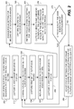
- Fig. 2 shows a flowchart of the preferred embodiment of the method of the invention as used when the camera is in a preview mode where images are captured and immediately displayed.
- the process begins in 200 when the camera or digital capture device is turned ON with the camera in a default focus setting.
- a video frame is captured and sent to the display.
- the focus setting is changed by an amount (for example 1 diopter or, the amount as corresponds to the depth of field of the lens e.g. 1 focus zone, at that focus setting) for the capture of a first set of autofocus images.
- the first set of autofocus images are captured and temporarily stored.
- the focus system is then returned to the setting for video frame capture in 240.
- another video frame is captured and sent to the display.
- the focus setting is then changed by a second amount for the capture of a second set of autofocus images in 255.
- a second set of autofocus images is then captured in Step 260 and temporarily stored.
- the focus system is then returned to the setting for video frame capture in 265.
- another video frame is captured and sent to the display. While capturing the video frame in 270, the focus quality of the first and second sets of auto focus images are evaluated and focus values are produced for each autofocus image.
- techniques for evaluating a series autofocus images to produce focus values are well known in the art, example techniques can be found in United States Patents 5877809 , 6441855 , 6885819 and United States Patent Application 2003/0160886 .
- a decision is made based on whether the focus values for the first and second autofocus sets is the same within a selected threshold value.
- the process proceeds to 220. If the focus value of either the first or second set of autofocus images is higher (better focus quality) than the other and outside the threshold value, a defocus condition has been detected and the focus setting for subsequent video frame captures is adjusted toward the focus setting of the autofocus image set which has better focus quality in 280 and the process proceeds to 220.
- the rate of focus setting adjustment to correct for a detected defocus condition is selected based on the focus characteristics of the fast focus system and the imaging system of the camera.
- the rate of focus setting adjustment can be programmed into the autofocus system based on a calibration process performed during manufacturing. Alternately, the rate of focus setting adjustment can be progressively learned by the autofocus system during use based on the number of focus setting adjustments required to attain a stable degree of good focus quality.
- the process of the invention in another example for focusing in the preview mode as described in Fig. 2 also applies to focusing for still image captures.
- the camera is placed into preview mode prior to capture of the still image and the camera continues to focus itself in the preview mode as the scene content changes.
- the camera is then already focused when the operator pushes the capture button thereby instructing the camera to capture a still image.
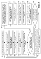
- Fig. 3 shows a flow chart for another example of method of the invention for ongoing continuous video capture.
- the process begins with the camera already in operation in a video mode as stated in 300.
- the focus setting is changed by an amount for capture of a first set of autofocus images.
- a first set of autofocus image is then captured in 320 and temporarily stored.
- the focus system is then returned to settings for video frame capture in 330.
- a video frame is captured, stored and typically sent to the display, although the sending of the video frame to the display is not required by the invention.
- the relative focus quality, determined through focus values for the first and second sets of autofocus images is determined in 350.
- the relative focus quality is evaluated through determined focus values for the last sets of the first set of autofocus images and the second set of autofocus images in 390.
- a decision on process direction is reached in 392 based on whether the last sets of the first set of autofocus images and the second set of autofocus images have the same focus values (relative focus quality) within a selected threshold value. If the last sets of the first set of autofocus images and the second set of autofocus images have the same focus values within the selected threshold value, the process loops back to Step 310. If either the first set of autofocus images or the second set of autofocus images have a higher focus value (better relative focus quality), above the selected threshold value, the process proceeds to 395. Where in 395, the focus system settings for video frame capture are adjusted toward the focus setting for the autofocus image set which has the better focus quality and the process loops back to 310.
- Step 365 the focus system settings are adjusted toward the focus settings for the set of autofocus images which produced better focus quality, and the process proceeds on to 370 as previously described.
- Fig. 4 shows an illustration of another example of the method of the invention where multiple autofocus images are included in both the first set of autofocus images and the second set of autofocus images.
- the first set of autofocus images 420 (labeled as AF1) is comprised of multiple images with decreasing steps of optical power while the second set of autofocus images 425 (labeled as AF2) is comprised of multiple images with increasing steps of optical power.
- This example enables a decision to be made as to whether a focus adjustment is needed for video frame 405 (labeled as Video) capture after 1 set of first set autofocus images 420, 1 set of second set autofocus images 425 and 1 video frame 405 have been captured.
- the measure of focus values (relative focus quality) that is produced is increased in accuracy.
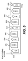
- Fig. 5 shows an illustration of a further example of the method of the invention in which the amount of change in optical power for autofocus images changes from set to set.
- a decision on focus quality is not reached until after 2 sets of first set of autofocus images 520 and 521 (labeled as AF1) and 2 sets of second set autofocus images 525 and 526 (labeled as AF2) and 2 video frames 505 (labeled as Video) have been captured.
- the need to make focus adjustments for video frame captures is then determined by comparing the relative focus quality of the 2 sets of first set autofocus images 520 and 521 to the 2 sets of second set autofocus images 525 and 526.
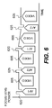
- Fig. 6 shows an illustration of a further example of the method of the invention, wherein the first set of autofocus images 620 (labeled as AF1) and second set of autofocus images 625 (labeled as AF2) are the same and each includes decreasing and increasing steps of optical power. While the illustration of Fig. 6 shows one decreasing step and one increasing step, the number of decreasing and increasing steps in each set of autofocus images 620 or 625 could be more than one each.
- a decision as to whether a focus adjustment is needed for video frame 605 (labeled as Video) capture can be reached after one set of autofocus images 620 or 625 has been captured, the focus adjustment can then be implemented during the capture of the following video frame 605. This approach provides a further reduction in the number of out-of-focus video frames 605 produced because the defocus condition is detected faster.
- a focus evaluation using a process similar to that shown in Fig. 6 is possible for verification of focus prior to capture of a still image.
- the camera would focus itself in the preview mode as described in the flowchart of Fig. 2 , then when the operator pushes the capture button instructing the camera to capture a still image, a final evaluation of focus quality could be achieved by capturing several autofocus images with increasing and decreasing optical power of the focus lens.
- the autofocus images are then evaluated for relative focus quality and a decision is made as to whether a final focus adjustment is needed prior to capture of the still image.
- a focus system that provides for short exposure time and rapid readout of autofocus images to support the method described previously.
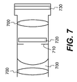
- Fig. 7 shows an illustration of an image capture device that includes features of the invention.
- the invention includes different types of rapid captures of autofocus images. Rapid captures of autofocus images require short exposure times and fast readout from the image sensor. Therefore, the focus system of the invention includes a lens assembly 700 that includes a focus lens 720 that is capable of rapid changes in optical power, 0.01 sec or less for a 1 diopter change as an illustrative example. Wherein the focus lens 720 is shown positioned behind the aperture stop 710, as that is the position which typically produces the shortest overall length of the image capture device. Other positions of the focus lens 720 or the aperture stop 710 are possible within the scope of the invention such as at the end of the lens where light enters.
- an image sensor which has panchromatic pixels which gather light from across the entire visible light spectrum as described in United States Patent Application 2007/0024931, filed on 07/28/2005 , entitled “Image Sensor with Improved Light Sensitivity", which is incorporated by reference as if fully set forth herein.
- the autofocus images can be comprised of panchromatic pixels exclusively that are readout in a subsampled manner.
- the sensor should be capable of readout of portions of the sensor to reduce the number of pixels that are readout in each image. In this way, autofocus images can be comprised of detected regions of interest such as faces or identified objects within the scene that is being imaged.
- the sensor should also be capable of binned readout of the pixels. Where binning is done by connecting neighboring pixels together electrically so the collected charge is shared amongst the binned pixels thereby increasing the effective size of the pixels and increasing the sensitivity of the pixels to light.
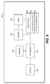
- FIG. 8 there is shown a simplified block diagram of an image capture device 800 such as a digital still camera, video camera, etc.
- Camera 800 includes a focus lens system such as lens 700.
- a sensor which can take the form of a CMOS or CCD image sensor as know in the art as for example image sensor 730 can be utilized with the present invention.
- An auto focus system 806 includes a focus evaluation section/circuit that can perform the focus evaluation as previously described and a focus adjustment section/circuit that performs the focus adjustment as described previously.
- Sections 808 and 810 can comprise hardware, software or a combination of both depending on the intended design requirements.
- a processor 812 which acts as the controller for camera 800 can comprise any one of a number of microprocessors, microcontrollers, digital signal processors, etc. Controller 812 in one example performs all of the autofocus techniques described above in collaboration with auotfocus system 806.
- Memory 814 which can include both volatile and nonvolatile memory stores data as well as the necessary programs used to operate camera 800.
- a display 816 which can comprise a Liquid Crystal Display (LCD) 816 can present images that are currently being captured as well as images previously captured as known in the art.
- LCD Liquid Crystal Display
Description
- The invention pertains to the field of autofocus systems for digital cameras. More specifically the invention pertains to the field of autofocus for image capture devices such as digital cameras that can be used for capturing a series of images for video, burst captures, as well as still images.
- Typically autofocus systems in digital cameras, for capturing still images or video, use a "through-the-lens" autofocus system that captures a series of 5-20 or more autofocus images taken with a moveable focus lens in different focusing positions. For an autofocus system that includes a variable focus lens with variable focal length or variable optical power for focusing, instead of moving the focus lens, the variable focus lens is adjusted electronically to provide 5-20 or more different focal lengths or optical powers for the autofocus images.
- After capture, the 5-20 or more autofocus images are analyzed for contrast to determine the focus lens condition that delivers the image with the highest contrast which is deemed the best focus condition. In the analysis, focus values are generated for each autofocus image based on the level of contrast present. The focus lens is then returned to the focus condition that produced the autofocus image with the highest contrast (highest focus value), or an interpolated position between two or more of the autofocus images, before a final image is captured and stored. This method of autofocusing is known as the "hill climb method" because it generates a sequence of focus values that increase in level until they pass over a peak, i.e., a "hill".
- "Through-the-lens" autofocus systems can be very accurate since they measure focus quality directly from autofocus images captured with the same high quality lens that is used to capture the final image. However "through the lens" autofocus systems can also be very slow due to the many movements of the focusing lens required and the many autofocus images that must be captured and analyzed. This slowness in time-to-focus contributes to the objectionable delay perceived by the user between the time when the capture button is pressed and the image is actually captured, which is known as shutter lag. It is desired to reduce shutter lag.
- During video capture, the autofocus images are typically derived from the same series of still images or frames that compose the video segment, consequently, the process of autofocusing causes 5-20 or more out-of-focus frames to be produced in the video each time the scene changes. As a result, during video capture with pan movements of the camera where the scene changes continuously, large portions of the video are actually out of focus. Ideally, the autofocus system would be faster when capturing video as well as still images, and in the case of video capture, each frame would be focused so that the number of out of focus frames is reduced. This is especially important in enabling images from videos to be printed or used in other fashions.
- Dual lens rangefinder modules can also provide a fast evaluation of focus conditions. Rangefinder modules can be purchased from Fuji Electric in several models such as the FM6260W. Dual lens rangefinder modules contain two lenses that are separated by a distance along with two matching sensor areas to enable matched pairs of low resolution images to be captured. The matched pairs of low resolution images are then analyzed for correlation between the two images to determine the offset between the two images caused by the separation between the two lenses. The offset information is then used along with the lens separation distance to calculate the distance to the scene by triangulation. The calculated distance to the scene is used to guide the use of the focus lens based on a calibration curve established between the distance to the scene as measured by the dual lens rangefinder module and a series of best focused images as produced by the through the lens autofocus system. The response time of the Fuji FM6260W modules is advertised as 0.004 sec in high sensitivity mode, which is well within the 1/30 sec required for video autofocus. However, the accuracy of dual lens rangefinder modules are typically influenced by changes in the environmental conditions such as changes in the temperature and/or humidity. So that typically these dual lens rangefinder modules are not used independently for autofocus in digital cameras but instead are used as a rough focus adjustment that is supplemented by a through the lens contrast based autofocus system. The problem with the dual lens rangefinder modules is that the calibration between the dual lens rangefinder module and the focus lens setting is not stable within the normal operating environment for digital cameras. Environmental conditions such as changes in temperature and humidity can cause the calculated distance to the scene produced by the dual lens rangefinder module to change by over 10% and in addition, the measured position of the moveable lens in the moveable lens control system is prone to environmentally induced changes as well. In addition, the dual lens rangefinder module adds the additional cost to the camera of the dual lens rangefinder module itself.
- In a through-the-lens split aperture device, as described United States Patent Publication
US20080002959 , a split aperture in the lens system is used to create images that can be interpreted for focus information. The split aperture creates two optical paths for the light passing through the lens to create at least two autofocus images at the sensor. By splitting the optical path at the aperture of the lens system, each of the two optical paths creates a full image without shading but reduced light intensity at the image sensor. By sequentially partially blocking two different portions of the aperture thereby splitting the aperture, two optical paths with different perspectives are created. The difference in perspective between the two optical paths causes the autofocus images to be displaced laterally in proportion to the degree of defocus and direction of defocus for an object in the image. However, the focus resolution of the split aperture method as measured by the number of detectable focus zones is limited by the effective separation achieved between the two optical paths that are created which is approximately 40% of the lens aperture. As lens apertures get smaller, the focus accuracy of this technique is diminished due to a lack of focus resolution, this is particularly true for small image capture devices such as are found in compact digital cameras, cellular telephones, laptop computers and other communication devices. - Therefore, a need exists for autofocus systems to be improved to provide less shutter lag for still capture and fewer out-of-focus frames for video while providing the focus resolution to enable accurate focusing.
-
US2007/0071433 discloses a camera having a contrast detector that successively detects contrast data of an object image that is formed on a light-receiving surface of an image sensor, and a focus detector that successively calculates a difference value between currently detected contrast data and previously detected contrast data, and that detects a focused situation on the basis of the difference value and the detected contrast data. The camera further has a focus adjuster that drives a photographing optical system so as continuously to shift an image-formed surface from a given position along an optical axis. While the photographing optical system is driven, the focus detector determines whether the image-formed surface surpasses a focused-position corresponding to a position of the light-receiving surface, on the basis of a decreasing-amount of the difference value. - It is an object of the present invention to provide an autofocus method according to claim 1 and an autofocus system according to claim 7 for image capture that improves upon the above identified problems.
- In the preferred embodiment, an autofocus system which is capable of very fast changes in focus over at least a relatively small portion of the focus range of the focusing system is utilized. When operating continuously in a repeating series of images or frames such as are found in preview mode or in video capture, autofocus images are captured before and after each image in the series wherein the autofocus images have different focus settings than the images in the series. The autofocus images are then evaluated for focus quality and the focus quality data is compared between autofocus images to determine whether focus adjustments are needed for the following image in the series. Focus adjustments are then carried out as needed based on the focus setting for the autofocus image with better focus quality. In this way, focus evaluations and focus adjustments can be accomplished frame by frame with a greatly reduced number of out-of-focus frames being produced when the focus conditions in the scene change.
- A variety of autofocus image sets are disclosed. One example uses alternating single step increases and decreases in optical power of the focus lens for first and second sets of autofocus images on either side of the capture of an image in the series. A further example uses alternating multiple step increases and decreases in optical power of the focus lens for first and second sets of autofocus images on either side of the capture of an image in the series. Another example uses alternating first and second steps of increases and decreases in optical power of the focus lens for first and second sets of autofocus images on either side of the capture of sets of images in the series.
-
-
Fig. 1 is an illustration of the optical power of the focus lens vs time using a preferred embodiment of the method of the invention. -
Fig. 2 is a flow chart for the method of the invention as used when the camera or other image capture device is used in a preview mode. -
Fig. 3 is a flow chart for the method of the invention as used when the camera or other image capture device is used in a continuous mode for video capture. -
Fig. 4 is an illustration of the optical power of the focus lens vs time using another example of the method of the invention. -
Fig. 5 is an illustration of the optical power of the focus lens vs time using a further example of the method of the invention. -
Fig. 6 is an illustration of the optical power of the focus lens vs time using yet another example of the method of the invention. -
Fig. 7 is a schematic cross section of an image capture device for a system embodiment of the invention. -
Fig. 8 is a simplified block diagram of an image capture device that can take advantage of the dithered focus evaluation in accordance the preferred embodiment and examples of the invention. - A preferred embodiment and examples of the invention seek to provide a fast autofocus system for a camera or other digital image capture device that can make focus evaluations and focus adjustments during the capture of a series of images such as in a video without causing a large number of the images captured to be out-of-focus.
- While the invention is described in terms of video capture, the invention is equally applicable to any capture of images in a series such as would occur for example in burst capture modes or in the capture of the images for preview display on an image capture device, etc. To this end, a preferred embodiment and examples of the invention add the capture of one or more autofocus images in-between the capture of each video image wherein, the autofocus image(s) is captured with a different focus setting than the video image. Since the focus quality is evaluated between each video frame, the conditions within the scene do not change a large amount frame to frame so the focus evaluation of the invention can be done with a small number of autofocus images.
- For autofocus to become fast enough to approach frame-by-frame autofocus at the typical video frame rate of 30 frames/second or faster, several improvements are needed throughout the autofocus system. First, a focus measurement system is needed that can provide a measure of focus quality that can be completed within 1/30 second or faster. The focus measurement must provide enough information to accurately guide the change in focus of the focus lens to achieve the desired focus quality within 1/30 second as well. Second, the focus lens control system must be fast enough to make focus adjustments within the available 1/30 sec between frames. There are a number of fast focus systems available that can be used to make focus adjustments within 1/30 sec. Examples of suitably fast focus systems that can be used for focus lenses in the invention include but are not limited to: piezoelectric motors for moving focus lenses; liquid lenses for variable optical power of focus lenses; fluid lenses for variable optical power of focus lenses; electroactive polymer lenses for variable optical power of focus lenses and dual range liquid crystal lenses for variable optical power of focus lenses as described in copending United States Patent Application by John N. Border, et al. filed on 09/25/2008, entitled "Dual Range Focus Element" and which is hereby incorporated by reference as if fully set forth herein.
- A fast focus system is used in a preferred embodiment to rapidly adjust the focus lens in an alternating manner between the focus setting for the video image and the focus settings for the autofocus images. The capture of the autofocus images must be rapid enough to not interfere with the capture of the video images, but at the same time, the autofocus images must have sufficient image quality to enable focus quality to be determined so that decisions on focus adjustments can be made for captures of video images.
-
Fig. 1 shows an illustration of the operation of the optical power of the focus lens using the method of one embodiment of the invention. In this case, autofocus images 120 (labeled as AF1) and 125 (labeled as AF2) are captured between captures of video images 105 (labeled as Video) wherein the autofocus images are captured in afirst set 120 followed by asecond set 125. Prior to the capture of each autofocus image, the focus lens is changed to a different focus setting from the video capture. As shown inFig. 1 , the first autofocus image set 120 has a focus setting with lower optical power and the second autofocus image set 125 has a focus setting with a higher optical power. The change between the focus settings for theautofocus images video images 105 is chosen to be an amount that causes the same amount of defocus but in opposite directions of defocus as compared to the focus setting for the video image that separates the autofocus images. - For simplicity the change in optical power from the focus setting for the video frame to the first set of autofocus images and the second set of autofocus images is shown as being the same in
Figs. 1 ,4 ,5 ,6 but the actual optical power change can be different to produce the same amount of defocus for the first set of autofocus images and the second set of autofocus images based on the focusing characteristics of the focus lens and the lens assembly. Since the focus settings for theautofocus images video image 105, if the video image is well focused, theautofocus images video image 105 that was captured between theautofocus images autofocus images - Conversely, if the
video image 105 is not well focused, the focus quality of one of the autofocus image sets 120 or 125 will be better than the focus quality of the other autofocus image set. In the invention, it is this difference in focus quality between the 2 sets ofautofocus images next video image 105 is captured. In addition, the degree of difference in focus quality between the 2 sets ofautofocus images next video image 105. A decision on whether a focus adjustment is needed forvideo frame capture 105 can be made using the process illustrated inFig. 1 after 1 set of firstset autofocus images 120, 1 set of secondset autofocus images 125 and 1video frame 105 has been captured. - After a decision on whether a focus adjustment is needed for
video frame capture 105, the focus adjustment can be carried out during the nextvideo frame capture 105 as shown inFig. 1 , where anoptical power change 110 is shown during thevideo frame capture 105. Alternately, the focus adjustment can be carried out in conjunction with the optical power changes for the autofocus images. The focus change for the autofocus image set 130 that follows thefocus adjustment 110, is the same amount as before the focus adjustment but the change is now relative to the new focus setting at the end of thevideo image 105 that was just captured so the optical power for the autofocus image set 130 is different from the previous autofocus set 125. -
Fig. 2 shows a flowchart of the preferred embodiment of the method of the invention as used when the camera is in a preview mode where images are captured and immediately displayed. The process begins in 200 when the camera or digital capture device is turned ON with the camera in a default focus setting. In 210, a video frame is captured and sent to the display. In 220, the focus setting is changed by an amount (for example 1 diopter or, the amount as corresponds to the depth of field of the lens e.g. 1 focus zone, at that focus setting) for the capture of a first set of autofocus images. In 230, the first set of autofocus images are captured and temporarily stored. The focus system is then returned to the setting for video frame capture in 240. In 250, another video frame is captured and sent to the display. The focus setting is then changed by a second amount for the capture of a second set of autofocus images in 255. - A second set of autofocus images is then captured in
Step 260 and temporarily stored. The focus system is then returned to the setting for video frame capture in 265. In 270, another video frame is captured and sent to the display. While capturing the video frame in 270, the focus quality of the first and second sets of auto focus images are evaluated and focus values are produced for each autofocus image. Wherein techniques for evaluating a series autofocus images to produce focus values are well known in the art, example techniques can be found in United States Patents5877809 ,6441855 ,6885819 and United States Patent Application2003/0160886 . In 275, a decision is made based on whether the focus values for the first and second autofocus sets is the same within a selected threshold value. If the difference between the focus values of the first and second autofocus sets is less than the selected threshold value, the process proceeds to 220. If the focus value of either the first or second set of autofocus images is higher (better focus quality) than the other and outside the threshold value, a defocus condition has been detected and the focus setting for subsequent video frame captures is adjusted toward the focus setting of the autofocus image set which has better focus quality in 280 and the process proceeds to 220. - In the focus setting adjustment process, the rate of focus setting adjustment to correct for a detected defocus condition is selected based on the focus characteristics of the fast focus system and the imaging system of the camera. The rate of focus setting adjustment can be programmed into the autofocus system based on a calibration process performed during manufacturing. Alternately, the rate of focus setting adjustment can be progressively learned by the autofocus system during use based on the number of focus setting adjustments required to attain a stable degree of good focus quality.
- It should be noted that the process of the invention in the preferred embodiment for autofocus of a burst capture will follow a process flow that is similar to that shown in
Fig. 2 where the video images are instead burst images. In addition, the burst images are sent to storage instead of being sent to the display. - It should also be noted that the process of the invention in another example for focusing in the preview mode as described in
Fig. 2 also applies to focusing for still image captures. In this case, the camera is placed into preview mode prior to capture of the still image and the camera continues to focus itself in the preview mode as the scene content changes. The camera is then already focused when the operator pushes the capture button thereby instructing the camera to capture a still image. -
Fig. 3 shows a flow chart for another example of method of the invention for ongoing continuous video capture. The process begins with the camera already in operation in a video mode as stated in 300. In 310, the focus setting is changed by an amount for capture of a first set of autofocus images. A first set of autofocus image is then captured in 320 and temporarily stored. The focus system is then returned to settings for video frame capture in 330. In 340, a video frame is captured, stored and typically sent to the display, although the sending of the video frame to the display is not required by the invention. The relative focus quality, determined through focus values for the first and second sets of autofocus images is determined in 350. A decision is then made in 360 based on whether the first and second sets of autofocus images have the same focus values (relative focus quality) within a threshold value. If the relative focus quality of the first and second sets of autofocus images is within the selected threshold value, the process continues on to 370. Where at 370 the focus setting is changed by an amount for capture of the second set of autofocus images. The second set of autofocus images are captured in 375. The focus system is then returned to focus settings for video frame capture in 380. A video frame is captured at 385, stored and typically sent to the display. - The relative focus quality is evaluated through determined focus values for the last sets of the first set of autofocus images and the second set of autofocus images in 390. A decision on process direction is reached in 392 based on whether the last sets of the first set of autofocus images and the second set of autofocus images have the same focus values (relative focus quality) within a selected threshold value. If the last sets of the first set of autofocus images and the second set of autofocus images have the same focus values within the selected threshold value, the process loops back to
Step 310. If either the first set of autofocus images or the second set of autofocus images have a higher focus value (better relative focus quality), above the selected threshold value, the process proceeds to 395. Where in 395, the focus system settings for video frame capture are adjusted toward the focus setting for the autofocus image set which has the better focus quality and the process loops back to 310. - If at 360, the relative focus quality of either the set of first autofocus images or the set of second autofocus images is determined to have a higher focus value (better focus quality) beyond the threshold value, the process proceeds to Step 365. Where at 365 the focus system settings are adjusted toward the focus settings for the set of autofocus images which produced better focus quality, and the process proceeds on to 370 as previously described.
-
Fig. 4 shows an illustration of another example of the method of the invention where multiple autofocus images are included in both the first set of autofocus images and the second set of autofocus images. In this example, the first set of autofocus images 420 (labeled as AF1) is comprised of multiple images with decreasing steps of optical power while the second set of autofocus images 425 (labeled as AF2) is comprised of multiple images with increasing steps of optical power. This example enables a decision to be made as to whether a focus adjustment is needed for video frame 405 (labeled as Video) capture after 1 set of firstset autofocus images 420, 1 set of secondset autofocus images 425 and 1video frame 405 have been captured. In addition, since multiple autofocus images with different focus settings are captured within the first and second sets ofautofocus images -
Fig. 5 shows an illustration of a further example of the method of the invention in which the amount of change in optical power for autofocus images changes from set to set. In this case, a decision on focus quality is not reached until after 2 sets of first set ofautofocus images 520 and 521 (labeled as AF1) and 2 sets of secondset autofocus images 525 and 526 (labeled as AF2) and 2 video frames 505 (labeled as Video) have been captured. The need to make focus adjustments for video frame captures is then determined by comparing the relative focus quality of the 2 sets of firstset autofocus images set autofocus images -
Fig. 6 shows an illustration of a further example of the method of the invention, wherein the first set of autofocus images 620 (labeled as AF1) and second set of autofocus images 625 (labeled as AF2) are the same and each includes decreasing and increasing steps of optical power. While the illustration ofFig. 6 shows one decreasing step and one increasing step, the number of decreasing and increasing steps in each set ofautofocus images autofocus images video frame 605. This approach provides a further reduction in the number of out-of-focus video frames 605 produced because the defocus condition is detected faster. - It should be noted that a focus evaluation using a process similar to that shown in
Fig. 6 is possible for verification of focus prior to capture of a still image. In this case, the camera would focus itself in the preview mode as described in the flowchart ofFig. 2 , then when the operator pushes the capture button instructing the camera to capture a still image, a final evaluation of focus quality could be achieved by capturing several autofocus images with increasing and decreasing optical power of the focus lens. The autofocus images are then evaluated for relative focus quality and a decision is made as to whether a final focus adjustment is needed prior to capture of the still image. - In a yet further example of the invention, a focus system is disclosed that provides for short exposure time and rapid readout of autofocus images to support the method described previously.
Fig. 7 shows an illustration of an image capture device that includes features of the invention. The invention includes different types of rapid captures of autofocus images. Rapid captures of autofocus images require short exposure times and fast readout from the image sensor. Therefore, the focus system of the invention includes alens assembly 700 that includes afocus lens 720 that is capable of rapid changes in optical power, 0.01 sec or less for a 1 diopter change as an illustrative example. Wherein thefocus lens 720 is shown positioned behind theaperture stop 710, as that is the position which typically produces the shortest overall length of the image capture device. Other positions of thefocus lens 720 or theaperture stop 710 are possible within the scope of the invention such as at the end of the lens where light enters. - To increase the efficiency of light gathering by the
image sensor 730, an image sensor is used which has panchromatic pixels which gather light from across the entire visible light spectrum as described in United States Patent Application2007/0024931, filed on 07/28/2005 , entitled "Image Sensor with Improved Light Sensitivity", which is incorporated by reference as if fully set forth herein. For higher light sensitivity and faster capture times, the autofocus images can be comprised of panchromatic pixels exclusively that are readout in a subsampled manner. In addition, the sensor should be capable of readout of portions of the sensor to reduce the number of pixels that are readout in each image. In this way, autofocus images can be comprised of detected regions of interest such as faces or identified objects within the scene that is being imaged. The sensor should also be capable of binned readout of the pixels. Where binning is done by connecting neighboring pixels together electrically so the collected charge is shared amongst the binned pixels thereby increasing the effective size of the pixels and increasing the sensitivity of the pixels to light. - Referring to
Fig. 8 , there is shown a simplified block diagram of animage capture device 800 such as a digital still camera, video camera, etc.Camera 800 includes a focus lens system such aslens 700. A sensor which can take the form of a CMOS or CCD image sensor as know in the art as forexample image sensor 730 can be utilized with the present invention. Anauto focus system 806 includes a focus evaluation section/circuit that can perform the focus evaluation as previously described and a focus adjustment section/circuit that performs the focus adjustment as described previously.Sections - A
processor 812 which acts as the controller forcamera 800 can comprise any one of a number of microprocessors, microcontrollers, digital signal processors, etc.Controller 812 in one example performs all of the autofocus techniques described above in collaboration withauotfocus system 806.Memory 814 which can include both volatile and nonvolatile memory stores data as well as the necessary programs used to operatecamera 800. Adisplay 816 which can comprise a Liquid Crystal Display (LCD) 816 can present images that are currently being captured as well as images previously captured as known in the art. -
- 105 Video frame
- 110 Focus adjustment during a video frame
- 120 Autofocus image in first set of autofocus images
- 125 Autofocus image in second set of autofocus images
- 130 Autofocus image in first set of autofocus images after a focus adjustment for video capture
- 200 Process Block
- 210 Process Block
- 220 Process Block
- 230 Process Block
- 240 Process Block
- 250 Process Block
- 255 Process Block
- 260 Process Block
- 265 Process Block
- 270 Process Block
- 275 Process Block
- 280 Process Block
- 300 Process Block
- 310 Process Block
- 320 Process Block
- 330 Process Block
- 340 Process Block
- 350 Process Block
- 360 Process Block
- 365 Process Block
- 370 Process Block
- 375 Process Block
- 380 Process Block
- 385 Process Block
- 390 Process Block
- 392 Process Block
- 395 Process Block
- 405 Video frame
- 420 Autofocus image in first set of autofocus images
- 425 Autofocus image in second set of autofocus images
- 505 Video frame
- 520 First autofocus image in first set of autofocus images
- 521 Second autofocus image in first set of autofocus images
- 525 First autofocus image in second set of autofocus images
- 526 Second autofocus image in second set of autofocus images
- 605 Video frame
- 620 Autofocus image in first set of autofocus images
- 625 Autofocus image in second set of autofocus images
- 700 Lens assembly
- 710 Aperture stop
- 720 Focus lens
- 730 Image sensor
- 800 Image capture device
- 802 Lens
- 804 Sensor
- 806 Auto Focus section
- 808 Focus evaluation section
- 810 Focus adjustment section
- 812 Processor
- 814 Memory
- 816 Display
Claims (9)
- A method for auto focusing an image capture device (800) that can capture several series of video images to be stored, comprising:capturing an autofocus image (120, 420, 520, 620) in a first set with a first focus setting, wherein said autofocus image is not one of the series of video images to be stored;capturing a first series of video images (105,405,505,605) with a focus setting for video image capture, after capturing the first set;capturing an autofocus image (125, 425, 525, 625) in a second set with a second focus setting, after capturing the first series of video images, wherein the autofocus images in the first and second sets are captured with different focus settings than the focus setting for video image capture; wherein the first and second focus settings cause defocus in opposite directions compared to the focus setting for video image capture; and wherein the first and second focus settings are chosen to cause substantially the same amount of defocus in opposite directions of defocus compared to the focus setting for video image capture;evaluating a focus quality of the autofocus images in the first and second sets;determining whether a focus adjustment is needed before the capture of a further series of video images and either (i) adjusting the focus setting toward the focus setting of the autofocus image having a better focus quality, if it is determined that the focus setting for video image capture needs to be adjusted based on a difference in focus quality between the autofocus images (120, 125) from the first and second sets; or (ii) not adjusting the focus setting for video image capture if the difference in focus quality between the autofocus images from the first and second sets is less than a selected threshold value; andcapturing a further series of video images.
- A method as defined in claim 1, wherein:the method includes capturing multiple autofocus images (420) in the first set, with each autofocus image in the first set being captured with decreasing steps of optical power compared to the focus setting for video image capture; andthe method includes capturing multiple autofocus images (425) in the second set, with each autofocus image in the second set being captured with increasing steps of optical power compared to the focus setting for video image capture.
- A method as defined in claim 1, wherein:the method includes capturing a second series of video images with the focus setting for video image capture, after capturing the second set;the method includes capturing an autofocus image (521) in an additional first set with a third focus setting having an optical power that is changed from the first focus setting, after capturing the second series of video images;the method includes capturing a third series of video images with the focus setting for video image capture, after capturing the additional first set;the method includes capturing an autofocus image (526) in an additional second set with a fourth focus setting having an optical power that is changed from the second focus setting, after capturing the third series of video images andadjusting the focus setting for video image capture is based on comparing the focus quality of the autofocus images of the two first sets to the autofocus images of the two second sets.
- A method as defined in claim 3, wherein:the first focus setting has an optical power that is greater than the third optical setting; andthe fourth focus setting has an optical power that is greater than the second optical setting.
- A method as defined in claim 1, wherein:the method includes capturing multiple autofocus images (620) in the first set, wherein the autofocus images in the first set have decreasing and increasing steps of optical power compared to the focus setting for video image capture; andthe method includes capturing multiple autofocus images (625) in the second set, wherein the autofocus images in the second set have decreasing and increasing steps of optical power compared to the focus setting for video image capture.
- A method as defined in any one of the previous claims wherein the image capture device has an focus system including a lens assembly that includes a focus lens capable of changing optical power by 1 diopter in 0.01 seconds or less.
- An image capture device (800), comprising:a lens (802);a sensor (804) located in the optical path of the lens;an autofocus system (806) coupled to the lens for adjusting the focus of the lens, the autofocus system including a focus evaluation section (808) for use in evaluating the focus quality of autofocus images and a focus adjustment section (810) responsive to the focus evaluation section for adjusting the focus setting of the lens; anda processor (812) which acts as the controller for the image capture device and, in collaboration with the autofocus system, is configured to control the image capture device to:capture an autofocus image (120, 420, 520, 620) in a first set with a first focus setting, wherein said autofocus image is not one of a series of video images (105, 405, 505, 605) to be stored;capture a first series of video images (105,405,505,605) with a focus setting for video image capture, after capturing the first set;capture an autofocus image (125, 425, 525, 625) in a second set with a second focus setting, after capturing the first series of video images, wherein the autofocus images in the first and second sets are captured with different focus settings than the focus setting for video image capture; wherein the first and second focus settings cause defocus in opposite directions compared to the focus setting for video image capture; and wherein the first and second focus settings are chosen to cause substantially the same amount of defocus in opposite directions of defocus compared to the focus setting for video image capture;evaluate, in the focus evaluation section, a focus quality of the autofocus images in the first and second sets;determine whether a focus adjustment is needed before the capture of a further series of video images and either (i) adjust, in the focus adjustment section, the focus setting for video image capture toward the focus setting of the autofocus image having a better focus quality, if it is determined that the focus setting for video image capture needs to be adjusted; or (ii) not adjust the focus setting for video image capture if the difference in focus quality between the autofocus images from the first and second sets is less than a selected threshold value; andcapture a further series of video images.
- An image capture device as defined in claim 7, wherein the image capture device further comprises a memory (814) for storing data as well as programs used to operate the image capture device.
- An image capture device as defined in claim 7 or claim 8, wherein the focus lens is either a moveable focus lens having different focussing positions or a variable focus lens adjustable electronically to provide a plurality of focal lengths for the autofocus images.
Applications Claiming Priority (2)
| Application Number | Priority Date | Filing Date | Title |
|---|---|---|---|
| US12/250,589 US8164682B2 (en) | 2008-10-14 | 2008-10-14 | Dithered focus evaluation |
| PCT/US2009/005533 WO2010044831A1 (en) | 2008-10-14 | 2009-10-09 | Dithered focus evaluation |
Publications (2)
| Publication Number | Publication Date |
|---|---|
| EP2335404A1 EP2335404A1 (en) | 2011-06-22 |
| EP2335404B1 true EP2335404B1 (en) | 2016-10-05 |
Family
ID=41323379
Family Applications (1)
| Application Number | Title | Priority Date | Filing Date |
|---|---|---|---|
| EP09740550.0A Active EP2335404B1 (en) | 2008-10-14 | 2009-10-09 | Dithered focus evaluation |
Country Status (5)
| Country | Link |
|---|---|
| US (1) | US8164682B2 (en) |
| EP (1) | EP2335404B1 (en) |
| JP (1) | JP5745416B2 (en) |
| CN (1) | CN102172013B (en) |
| WO (1) | WO2010044831A1 (en) |
Cited By (1)
| Publication number | Priority date | Publication date | Assignee | Title |
|---|---|---|---|---|
| US20220174222A1 (en) * | 2020-11-30 | 2022-06-02 | Boe Technology Group Co., Ltd. | Method for marking focused pixel, electronic device, storage medium, and chip |
Families Citing this family (23)
| Publication number | Priority date | Publication date | Assignee | Title |
|---|---|---|---|---|
| US8139130B2 (en) | 2005-07-28 | 2012-03-20 | Omnivision Technologies, Inc. | Image sensor with improved light sensitivity |
| US8274715B2 (en) | 2005-07-28 | 2012-09-25 | Omnivision Technologies, Inc. | Processing color and panchromatic pixels |
| US7916362B2 (en) | 2006-05-22 | 2011-03-29 | Eastman Kodak Company | Image sensor with improved light sensitivity |
| US8031258B2 (en) | 2006-10-04 | 2011-10-04 | Omnivision Technologies, Inc. | Providing multiple video signals from single sensor |
| US8224082B2 (en) * | 2009-03-10 | 2012-07-17 | Omnivision Technologies, Inc. | CFA image with synthetic panchromatic image |
| US8068153B2 (en) * | 2009-03-27 | 2011-11-29 | Omnivision Technologies, Inc. | Producing full-color image using CFA image |
| US8045024B2 (en) * | 2009-04-15 | 2011-10-25 | Omnivision Technologies, Inc. | Producing full-color image with reduced motion blur |
| US8203633B2 (en) * | 2009-05-27 | 2012-06-19 | Omnivision Technologies, Inc. | Four-channel color filter array pattern |
| US8237831B2 (en) * | 2009-05-28 | 2012-08-07 | Omnivision Technologies, Inc. | Four-channel color filter array interpolation |
| US8125546B2 (en) * | 2009-06-05 | 2012-02-28 | Omnivision Technologies, Inc. | Color filter array pattern having four-channels |
| US8253832B2 (en) * | 2009-06-09 | 2012-08-28 | Omnivision Technologies, Inc. | Interpolation for four-channel color filter array |
| US8964103B2 (en) * | 2010-02-16 | 2015-02-24 | Blackberry Limited | Method and apparatus for reducing continuous autofocus power consumption |
| US9118842B2 (en) * | 2010-09-16 | 2015-08-25 | Intellectual Ventures Fund 83 Llc | Producing focused videos from single captured video |
| DE102011121928B4 (en) * | 2011-08-01 | 2015-03-05 | Physik Instrumente (Pi) Gmbh & Co. Kg | Arrangement for operating a dynamic nanofocusing system |
| CN103297665A (en) * | 2012-02-22 | 2013-09-11 | 庄佑华 | Image acquisition system |
| CN103475818A (en) * | 2013-09-03 | 2013-12-25 | 小米科技有限责任公司 | Shooting method and device and terminal device |
| CN104717418A (en) * | 2013-12-16 | 2015-06-17 | 腾讯科技(深圳)有限公司 | Focusing method, device and electronic equipment |
| US9575221B2 (en) | 2013-12-31 | 2017-02-21 | Cognex Corporation | Systems and methods reduce temperature induced drift effects on a liquid lens |
| US10690816B2 (en) | 2013-12-31 | 2020-06-23 | Cognex Corporation | Systems and methods reduce temperature induced drift effects on a liquid lens |
| CN103780840B (en) * | 2014-01-21 | 2016-06-08 | 上海果壳电子有限公司 | Two camera shooting image forming apparatus of a kind of high-quality imaging and method thereof |
| CN103763477B (en) * | 2014-02-21 | 2016-06-08 | 上海果壳电子有限公司 | A kind of dual camera claps back focusing imaging device and method |
| CN105354557B (en) * | 2014-11-03 | 2019-04-16 | 苏州思源科安信息技术有限公司 | A kind of bio-identification forgery proofing biopsy method |
| CN105120153B (en) * | 2015-08-20 | 2018-01-19 | 广东欧珀移动通信有限公司 | A kind of image capturing method and device |
Citations (2)
| Publication number | Priority date | Publication date | Assignee | Title |
|---|---|---|---|---|
| US20070071433A1 (en) * | 2005-09-26 | 2007-03-29 | Pentax Corporation | Camera with autofocus system |
| US20080002959A1 (en) * | 2006-06-29 | 2008-01-03 | Eastman Kodak Company | Autofocusing still and video images |
Family Cites Families (25)
| Publication number | Priority date | Publication date | Assignee | Title |
|---|---|---|---|---|
| JPS6020111A (en) | 1983-07-14 | 1985-02-01 | Fuji Electric Corp Res & Dev Ltd | Distance measuring device |
| JP3943613B2 (en) * | 1995-10-02 | 2007-07-11 | キヤノン株式会社 | Imaging device and lens unit |
| JP3752510B2 (en) | 1996-04-15 | 2006-03-08 | イーストマン コダック カンパニー | Automatic subject detection method for images |
| JP3726630B2 (en) * | 2000-03-27 | 2005-12-14 | コニカミノルタフォトイメージング株式会社 | Digital still camera |
| US6453124B2 (en) | 2000-03-27 | 2002-09-17 | Minolta Co., Ltd. | Digital camera |
| US6441855B1 (en) | 2000-05-09 | 2002-08-27 | Eastman Kodak Company | Focusing device |
| JP4355847B2 (en) * | 2000-09-04 | 2009-11-04 | 富士フイルム株式会社 | Camera focus information display apparatus and method |
| JP3992992B2 (en) | 2002-02-19 | 2007-10-17 | 株式会社リコー | Subject image acquisition device |
| JP4198449B2 (en) | 2002-02-22 | 2008-12-17 | 富士フイルム株式会社 | Digital camera |
| JP3823921B2 (en) * | 2002-12-27 | 2006-09-20 | コニカミノルタフォトイメージング株式会社 | Imaging device |
| JP4581417B2 (en) * | 2004-01-16 | 2010-11-17 | ソニー株式会社 | Autofocus control device and method, recording medium, and program |
| JP4023457B2 (en) * | 2004-03-02 | 2007-12-19 | ソニー株式会社 | Autofocus control device and method, recording medium, and program |
| JP4649128B2 (en) * | 2004-06-15 | 2011-03-09 | キヤノン株式会社 | Automatic focus adjustment apparatus and imaging apparatus having the automatic focus apparatus |
| JP4607900B2 (en) | 2004-11-16 | 2011-01-05 | シチズンホールディングス株式会社 | Automatic focusing device |
| IL174531A0 (en) | 2005-04-06 | 2006-08-20 | Given Imaging Ltd | System and method for performing capsule endoscopy diagnosis in remote sites |
| US8430809B2 (en) | 2005-08-01 | 2013-04-30 | G. I View Ltd. | Capsule for use in small intestine |
| WO2007051147A2 (en) | 2005-10-26 | 2007-05-03 | Capso Vision, Inc. | Onboard data storage and method |
| JP2007150643A (en) * | 2005-11-28 | 2007-06-14 | Sony Corp | Solid state imaging element, driving method therefor, and imaging apparatus |
| JP2008051871A (en) * | 2006-08-22 | 2008-03-06 | Nikon Corp | Automatic focusing device |
| US7769229B2 (en) | 2006-11-30 | 2010-08-03 | Eastman Kodak Company | Processing images having color and panchromatic pixels |
| US8095000B2 (en) * | 2007-02-15 | 2012-01-10 | Panasonic Corporation | Camera system |
| US7729602B2 (en) * | 2007-03-09 | 2010-06-01 | Eastman Kodak Company | Camera using multiple lenses and image sensors operable in a default imaging mode |
| US7676146B2 (en) * | 2007-03-09 | 2010-03-09 | Eastman Kodak Company | Camera using multiple lenses and image sensors to provide improved focusing capability |
| DE102007017267A1 (en) | 2007-04-12 | 2008-10-16 | Siemens Ag | Method for improving the profitability of examinations or treatments with endoscopic capsules |
| US7667169B2 (en) * | 2008-05-22 | 2010-02-23 | Omnivision Technologies, Inc. | Image sensor with simultaneous auto-focus and image preview |
-
2008
- 2008-10-14 US US12/250,589 patent/US8164682B2/en active Active
-
2009
- 2009-10-09 WO PCT/US2009/005533 patent/WO2010044831A1/en active Application Filing
- 2009-10-09 JP JP2011532073A patent/JP5745416B2/en active Active
- 2009-10-09 CN CN200980139432.8A patent/CN102172013B/en active Active
- 2009-10-09 EP EP09740550.0A patent/EP2335404B1/en active Active
Patent Citations (2)
| Publication number | Priority date | Publication date | Assignee | Title |
|---|---|---|---|---|
| US20070071433A1 (en) * | 2005-09-26 | 2007-03-29 | Pentax Corporation | Camera with autofocus system |
| US20080002959A1 (en) * | 2006-06-29 | 2008-01-03 | Eastman Kodak Company | Autofocusing still and video images |
Cited By (1)
| Publication number | Priority date | Publication date | Assignee | Title |
|---|---|---|---|---|
| US20220174222A1 (en) * | 2020-11-30 | 2022-06-02 | Boe Technology Group Co., Ltd. | Method for marking focused pixel, electronic device, storage medium, and chip |
Also Published As
| Publication number | Publication date |
|---|---|
| WO2010044831A1 (en) | 2010-04-22 |
| EP2335404A1 (en) | 2011-06-22 |
| US8164682B2 (en) | 2012-04-24 |
| JP5745416B2 (en) | 2015-07-08 |
| JP2012506066A (en) | 2012-03-08 |
| CN102172013A (en) | 2011-08-31 |
| CN102172013B (en) | 2014-09-10 |
| US20100091169A1 (en) | 2010-04-15 |
Similar Documents
| Publication | Publication Date | Title |
|---|---|---|
| EP2335404B1 (en) | Dithered focus evaluation | |
| US7702229B2 (en) | Lens array assisted focus detection | |
| RU2456654C2 (en) | Image capturing device, control method thereof and data medium | |
| US7546030B2 (en) | Autofocus device and method | |
| US7405762B2 (en) | Camera having AF function | |
| US8953089B2 (en) | Imaging apparatus and controlling method therefor, and lens unit and controlling method therefor, and imaging system | |
| JP5618712B2 (en) | Automatic focusing device and imaging device | |
| JP2008026788A (en) | Imaging apparatus and focus control method | |
| US20060232700A1 (en) | Autofocus device and method | |
| US9444993B2 (en) | Focus detecting apparatus, lens apparatus including the same, image pickup apparatus, and method of detecting defocus amount | |
| CN101115146A (en) | Image-pickup apparatus and focus control method | |
| CN104580851A (en) | Image capture apparatus and method for controlling the same | |
| JP2014153509A (en) | Imaging device and imaging method | |
| WO2013054527A1 (en) | Image capture device, semiconductor integrated circuit, and image capture method | |
| EP3002940A1 (en) | Imaging apparatus and imaging method | |
| US7570298B2 (en) | Image-taking apparatus with first focus control such that in-focus position is searched for based on first signal and second focus control such that one of in-focus position and drive amount is determined based on second signal | |
| JP2008310072A (en) | Digital camera | |
| CN102833484B (en) | Picture pick-up device and control method thereof | |
| JP2013113857A (en) | Imaging device, and control method therefor | |
| JP5217942B2 (en) | Focus adjustment device and imaging device | |
| US8823860B2 (en) | Apparatus for auto-focusing detection, camera applying the same, and method for calculating distance to subject | |
| JP2009109792A (en) | Autofocusing device and camera using it | |
| KR20110027120A (en) | Image pickup apparatus | |
| JP2008026786A (en) | Imaging apparatus and focus control method | |
| JP4850623B2 (en) | Imaging apparatus and focus control method |
Legal Events
| Date | Code | Title | Description |
|---|---|---|---|
| PUAI | Public reference made under article 153(3) epc to a published international application that has entered the european phase |
Free format text: ORIGINAL CODE: 0009012 |
|
| 17P | Request for examination filed |
Effective date: 20110401 |
|
| AK | Designated contracting states |
Kind code of ref document: A1 Designated state(s): AT BE BG CH CY CZ DE DK EE ES FI FR GB GR HR HU IE IS IT LI LT LU LV MC MK MT NL NO PL PT RO SE SI SK SM TR |
|
| AX | Request for extension of the european patent |
Extension state: AL BA RS |
|
| RAP1 | Party data changed (applicant data changed or rights of an application transferred) |
Owner name: OMNIVISION TECHNOLOGIES, INC. |
|
| DAX | Request for extension of the european patent (deleted) | ||
| 17Q | First examination report despatched |
Effective date: 20150930 |
|
| GRAP | Despatch of communication of intention to grant a patent |
Free format text: ORIGINAL CODE: EPIDOSNIGR1 |
|
| INTG | Intention to grant announced |
Effective date: 20160404 |
|
| RIC1 | Information provided on ipc code assigned before grant |
Ipc: H04N 5/361 20110101ALI20160323BHEP Ipc: H04N 5/232 20060101AFI20160323BHEP |
|
| GRAJ | Information related to disapproval of communication of intention to grant by the applicant or resumption of examination proceedings by the epo deleted |
Free format text: ORIGINAL CODE: EPIDOSDIGR1 |
|
| GRAR | Information related to intention to grant a patent recorded |
Free format text: ORIGINAL CODE: EPIDOSNIGR71 |
|
| GRAS | Grant fee paid |
Free format text: ORIGINAL CODE: EPIDOSNIGR3 |
|
| GRAA | (expected) grant |
Free format text: ORIGINAL CODE: 0009210 |
|
| INTC | Intention to grant announced (deleted) | ||
| AK | Designated contracting states |
Kind code of ref document: B1 Designated state(s): AT BE BG CH CY CZ DE DK EE ES FI FR GB GR HR HU IE IS IT LI LT LU LV MC MK MT NL NO PL PT RO SE SI SK SM TR |
|
| INTG | Intention to grant announced |
Effective date: 20160829 |
|
| REG | Reference to a national code |
Ref country code: GB Ref legal event code: FG4D |
|
| REG | Reference to a national code |
Ref country code: CH Ref legal event code: EP |
|
| REG | Reference to a national code |
Ref country code: AT Ref legal event code: REF Ref document number: 835476 Country of ref document: AT Kind code of ref document: T Effective date: 20161015 |
|
| REG | Reference to a national code |
Ref country code: IE Ref legal event code: FG4D |
|
| REG | Reference to a national code |
Ref country code: DE Ref legal event code: R096 Ref document number: 602009041541 Country of ref document: DE |
|
| REG | Reference to a national code |
Ref country code: FR Ref legal event code: PLFP Year of fee payment: 8 |
|
| REG | Reference to a national code |
Ref country code: NL Ref legal event code: MP Effective date: 20161005 |
|
| REG | Reference to a national code |
Ref country code: LT Ref legal event code: MG4D |
|
| PG25 | Lapsed in a contracting state [announced via postgrant information from national office to epo] |
Ref country code: BE Free format text: LAPSE BECAUSE OF NON-PAYMENT OF DUE FEES Effective date: 20161031 Ref country code: LV Free format text: LAPSE BECAUSE OF FAILURE TO SUBMIT A TRANSLATION OF THE DESCRIPTION OR TO PAY THE FEE WITHIN THE PRESCRIBED TIME-LIMIT Effective date: 20161005 |
|
| REG | Reference to a national code |
Ref country code: AT Ref legal event code: MK05 Ref document number: 835476 Country of ref document: AT Kind code of ref document: T Effective date: 20161005 |
|
| PG25 | Lapsed in a contracting state [announced via postgrant information from national office to epo] |
Ref country code: LT Free format text: LAPSE BECAUSE OF FAILURE TO SUBMIT A TRANSLATION OF THE DESCRIPTION OR TO PAY THE FEE WITHIN THE PRESCRIBED TIME-LIMIT Effective date: 20161005 Ref country code: GR Free format text: LAPSE BECAUSE OF FAILURE TO SUBMIT A TRANSLATION OF THE DESCRIPTION OR TO PAY THE FEE WITHIN THE PRESCRIBED TIME-LIMIT Effective date: 20170106 Ref country code: SE Free format text: LAPSE BECAUSE OF FAILURE TO SUBMIT A TRANSLATION OF THE DESCRIPTION OR TO PAY THE FEE WITHIN THE PRESCRIBED TIME-LIMIT Effective date: 20161005 Ref country code: NO Free format text: LAPSE BECAUSE OF FAILURE TO SUBMIT A TRANSLATION OF THE DESCRIPTION OR TO PAY THE FEE WITHIN THE PRESCRIBED TIME-LIMIT Effective date: 20170105 |
|
| PG25 | Lapsed in a contracting state [announced via postgrant information from national office to epo] |
Ref country code: HR Free format text: LAPSE BECAUSE OF FAILURE TO SUBMIT A TRANSLATION OF THE DESCRIPTION OR TO PAY THE FEE WITHIN THE PRESCRIBED TIME-LIMIT Effective date: 20161005 Ref country code: BE Free format text: LAPSE BECAUSE OF FAILURE TO SUBMIT A TRANSLATION OF THE DESCRIPTION OR TO PAY THE FEE WITHIN THE PRESCRIBED TIME-LIMIT Effective date: 20161005 Ref country code: AT Free format text: LAPSE BECAUSE OF FAILURE TO SUBMIT A TRANSLATION OF THE DESCRIPTION OR TO PAY THE FEE WITHIN THE PRESCRIBED TIME-LIMIT Effective date: 20161005 Ref country code: NL Free format text: LAPSE BECAUSE OF FAILURE TO SUBMIT A TRANSLATION OF THE DESCRIPTION OR TO PAY THE FEE WITHIN THE PRESCRIBED TIME-LIMIT Effective date: 20161005 Ref country code: IS Free format text: LAPSE BECAUSE OF FAILURE TO SUBMIT A TRANSLATION OF THE DESCRIPTION OR TO PAY THE FEE WITHIN THE PRESCRIBED TIME-LIMIT Effective date: 20170205 Ref country code: PT Free format text: LAPSE BECAUSE OF FAILURE TO SUBMIT A TRANSLATION OF THE DESCRIPTION OR TO PAY THE FEE WITHIN THE PRESCRIBED TIME-LIMIT Effective date: 20170206 Ref country code: FI Free format text: LAPSE BECAUSE OF FAILURE TO SUBMIT A TRANSLATION OF THE DESCRIPTION OR TO PAY THE FEE WITHIN THE PRESCRIBED TIME-LIMIT Effective date: 20161005 Ref country code: ES Free format text: LAPSE BECAUSE OF FAILURE TO SUBMIT A TRANSLATION OF THE DESCRIPTION OR TO PAY THE FEE WITHIN THE PRESCRIBED TIME-LIMIT Effective date: 20161005 Ref country code: PL Free format text: LAPSE BECAUSE OF FAILURE TO SUBMIT A TRANSLATION OF THE DESCRIPTION OR TO PAY THE FEE WITHIN THE PRESCRIBED TIME-LIMIT Effective date: 20161005 |
|
| REG | Reference to a national code |
Ref country code: DE Ref legal event code: R097 Ref document number: 602009041541 Country of ref document: DE |
|
| REG | Reference to a national code |
Ref country code: IE Ref legal event code: MM4A |
|
| PG25 | Lapsed in a contracting state [announced via postgrant information from national office to epo] |
Ref country code: MC Free format text: LAPSE BECAUSE OF FAILURE TO SUBMIT A TRANSLATION OF THE DESCRIPTION OR TO PAY THE FEE WITHIN THE PRESCRIBED TIME-LIMIT Effective date: 20161005 Ref country code: SK Free format text: LAPSE BECAUSE OF FAILURE TO SUBMIT A TRANSLATION OF THE DESCRIPTION OR TO PAY THE FEE WITHIN THE PRESCRIBED TIME-LIMIT Effective date: 20161005 Ref country code: DK Free format text: LAPSE BECAUSE OF FAILURE TO SUBMIT A TRANSLATION OF THE DESCRIPTION OR TO PAY THE FEE WITHIN THE PRESCRIBED TIME-LIMIT Effective date: 20161005 Ref country code: EE Free format text: LAPSE BECAUSE OF FAILURE TO SUBMIT A TRANSLATION OF THE DESCRIPTION OR TO PAY THE FEE WITHIN THE PRESCRIBED TIME-LIMIT Effective date: 20161005 Ref country code: CZ Free format text: LAPSE BECAUSE OF FAILURE TO SUBMIT A TRANSLATION OF THE DESCRIPTION OR TO PAY THE FEE WITHIN THE PRESCRIBED TIME-LIMIT Effective date: 20161005 Ref country code: RO Free format text: LAPSE BECAUSE OF FAILURE TO SUBMIT A TRANSLATION OF THE DESCRIPTION OR TO PAY THE FEE WITHIN THE PRESCRIBED TIME-LIMIT Effective date: 20161005 |
|
| PLBE | No opposition filed within time limit |
Free format text: ORIGINAL CODE: 0009261 |
|
| STAA | Information on the status of an ep patent application or granted ep patent |
Free format text: STATUS: NO OPPOSITION FILED WITHIN TIME LIMIT |
|
| PG25 | Lapsed in a contracting state [announced via postgrant information from national office to epo] |
Ref country code: LU Free format text: LAPSE BECAUSE OF NON-PAYMENT OF DUE FEES Effective date: 20161009 Ref country code: BG Free format text: LAPSE BECAUSE OF FAILURE TO SUBMIT A TRANSLATION OF THE DESCRIPTION OR TO PAY THE FEE WITHIN THE PRESCRIBED TIME-LIMIT Effective date: 20170105 Ref country code: SM Free format text: LAPSE BECAUSE OF FAILURE TO SUBMIT A TRANSLATION OF THE DESCRIPTION OR TO PAY THE FEE WITHIN THE PRESCRIBED TIME-LIMIT Effective date: 20161005 Ref country code: IT Free format text: LAPSE BECAUSE OF FAILURE TO SUBMIT A TRANSLATION OF THE DESCRIPTION OR TO PAY THE FEE WITHIN THE PRESCRIBED TIME-LIMIT Effective date: 20161005 |
|
| 26N | No opposition filed |
Effective date: 20170706 |
|
| REG | Reference to a national code |
Ref country code: FR Ref legal event code: PLFP Year of fee payment: 9 |
|
| PG25 | Lapsed in a contracting state [announced via postgrant information from national office to epo] |
Ref country code: SI Free format text: LAPSE BECAUSE OF FAILURE TO SUBMIT A TRANSLATION OF THE DESCRIPTION OR TO PAY THE FEE WITHIN THE PRESCRIBED TIME-LIMIT Effective date: 20161005 Ref country code: IE Free format text: LAPSE BECAUSE OF NON-PAYMENT OF DUE FEES Effective date: 20161009 |
|
| PG25 | Lapsed in a contracting state [announced via postgrant information from national office to epo] |
Ref country code: HU Free format text: LAPSE BECAUSE OF FAILURE TO SUBMIT A TRANSLATION OF THE DESCRIPTION OR TO PAY THE FEE WITHIN THE PRESCRIBED TIME-LIMIT; INVALID AB INITIO Effective date: 20091009 Ref country code: CY Free format text: LAPSE BECAUSE OF FAILURE TO SUBMIT A TRANSLATION OF THE DESCRIPTION OR TO PAY THE FEE WITHIN THE PRESCRIBED TIME-LIMIT Effective date: 20161005 |
|
| PG25 | Lapsed in a contracting state [announced via postgrant information from national office to epo] |
Ref country code: MK Free format text: LAPSE BECAUSE OF FAILURE TO SUBMIT A TRANSLATION OF THE DESCRIPTION OR TO PAY THE FEE WITHIN THE PRESCRIBED TIME-LIMIT Effective date: 20161005 Ref country code: TR Free format text: LAPSE BECAUSE OF FAILURE TO SUBMIT A TRANSLATION OF THE DESCRIPTION OR TO PAY THE FEE WITHIN THE PRESCRIBED TIME-LIMIT Effective date: 20161005 Ref country code: MT Free format text: LAPSE BECAUSE OF NON-PAYMENT OF DUE FEES Effective date: 20161031 |
|
| REG | Reference to a national code |
Ref country code: FR Ref legal event code: PLFP Year of fee payment: 10 |
|
| REG | Reference to a national code |
Ref country code: DE Ref legal event code: R079 Ref document number: 602009041541 Country of ref document: DE Free format text: PREVIOUS MAIN CLASS: H04N0005232000 Ipc: H04N0023600000 |
|
| P01 | Opt-out of the competence of the unified patent court (upc) registered |
Effective date: 20230419 |
|
| PGFP | Annual fee paid to national office [announced via postgrant information from national office to epo] |
Ref country code: GB Payment date: 20230914 Year of fee payment: 15 |
|
| PGFP | Annual fee paid to national office [announced via postgrant information from national office to epo] |
Ref country code: FR Payment date: 20230914 Year of fee payment: 15 |
|
| PGFP | Annual fee paid to national office [announced via postgrant information from national office to epo] |
Ref country code: DE Payment date: 20230915 Year of fee payment: 15 Ref country code: CH Payment date: 20231102 Year of fee payment: 15 |