JP5744860B2 - Side-pumped monolithic solid-state laser and its application - Google Patents
Side-pumped monolithic solid-state laser and its application Download PDFInfo
- Publication number
- JP5744860B2 JP5744860B2 JP2012515388A JP2012515388A JP5744860B2 JP 5744860 B2 JP5744860 B2 JP 5744860B2 JP 2012515388 A JP2012515388 A JP 2012515388A JP 2012515388 A JP2012515388 A JP 2012515388A JP 5744860 B2 JP5744860 B2 JP 5744860B2
- Authority
- JP
- Japan
- Prior art keywords
- laser
- gain medium
- solid
- treatment device
- pump
- Prior art date
- Legal status (The legal status is an assumption and is not a legal conclusion. Google has not performed a legal analysis and makes no representation as to the accuracy of the status listed.)
- Active
Links
- 239000007787 solid Substances 0.000 claims description 122
- 238000001816 cooling Methods 0.000 claims description 110
- 238000011282 treatment Methods 0.000 claims description 97
- 239000000463 material Substances 0.000 claims description 95
- 230000003287 optical effect Effects 0.000 claims description 77
- 239000013078 crystal Substances 0.000 claims description 65
- 239000000835 fiber Substances 0.000 claims description 59
- 239000007788 liquid Substances 0.000 claims description 35
- 238000010521 absorption reaction Methods 0.000 claims description 29
- 230000008878 coupling Effects 0.000 claims description 27
- 238000010168 coupling process Methods 0.000 claims description 27
- 238000005859 coupling reaction Methods 0.000 claims description 27
- 238000000034 method Methods 0.000 claims description 27
- 239000000872 buffer Substances 0.000 claims description 21
- 229910052751 metal Inorganic materials 0.000 claims description 21
- 239000002184 metal Substances 0.000 claims description 20
- 239000013307 optical fiber Substances 0.000 claims description 20
- 238000009826 distribution Methods 0.000 claims description 14
- 229910052775 Thulium Inorganic materials 0.000 claims description 10
- 230000005540 biological transmission Effects 0.000 claims description 10
- 239000000919 ceramic Substances 0.000 claims description 10
- 239000002178 crystalline material Substances 0.000 claims description 9
- 238000002310 reflectometry Methods 0.000 claims description 9
- 229910052689 Holmium Inorganic materials 0.000 claims description 8
- 239000002826 coolant Substances 0.000 claims description 7
- 239000012530 fluid Substances 0.000 claims description 7
- 230000001225 therapeutic effect Effects 0.000 claims description 7
- 238000004146 energy storage Methods 0.000 claims description 6
- KJZYNXUDTRRSPN-UHFFFAOYSA-N holmium atom Chemical compound [Ho] KJZYNXUDTRRSPN-UHFFFAOYSA-N 0.000 claims description 6
- 229910052691 Erbium Inorganic materials 0.000 claims description 5
- 238000012634 optical imaging Methods 0.000 claims description 4
- 229910052769 Ytterbium Inorganic materials 0.000 claims description 3
- 229910052804 chromium Inorganic materials 0.000 claims description 3
- 238000002560 therapeutic procedure Methods 0.000 claims description 3
- VYZAMTAEIAYCRO-UHFFFAOYSA-N Chromium Chemical compound [Cr] VYZAMTAEIAYCRO-UHFFFAOYSA-N 0.000 claims description 2
- UYAHIZSMUZPPFV-UHFFFAOYSA-N erbium Chemical compound [Er] UYAHIZSMUZPPFV-UHFFFAOYSA-N 0.000 claims description 2
- 238000010191 image analysis Methods 0.000 claims description 2
- 229910052761 rare earth metal Inorganic materials 0.000 claims description 2
- 238000007789 sealing Methods 0.000 claims description 2
- 229910052779 Neodymium Inorganic materials 0.000 claims 1
- 239000011651 chromium Substances 0.000 claims 1
- QEFYFXOXNSNQGX-UHFFFAOYSA-N neodymium atom Chemical compound [Nd] QEFYFXOXNSNQGX-UHFFFAOYSA-N 0.000 claims 1
- 239000012782 phase change material Substances 0.000 claims 1
- 150000002910 rare earth metals Chemical class 0.000 claims 1
- NAWDYIZEMPQZHO-UHFFFAOYSA-N ytterbium Chemical compound [Yb] NAWDYIZEMPQZHO-UHFFFAOYSA-N 0.000 claims 1
- 210000001519 tissue Anatomy 0.000 description 58
- 230000008901 benefit Effects 0.000 description 44
- JNDMLEXHDPKVFC-UHFFFAOYSA-N aluminum;oxygen(2-);yttrium(3+) Chemical compound [O-2].[O-2].[O-2].[Al+3].[Y+3] JNDMLEXHDPKVFC-UHFFFAOYSA-N 0.000 description 42
- 229910019901 yttrium aluminum garnet Inorganic materials 0.000 description 42
- 239000007789 gas Substances 0.000 description 31
- 239000010410 layer Substances 0.000 description 31
- 239000004065 semiconductor Substances 0.000 description 23
- 230000007704 transition Effects 0.000 description 22
- 238000000576 coating method Methods 0.000 description 20
- 230000000694 effects Effects 0.000 description 18
- 238000012423 maintenance Methods 0.000 description 18
- XLYOFNOQVPJJNP-UHFFFAOYSA-N water Substances O XLYOFNOQVPJJNP-UHFFFAOYSA-N 0.000 description 18
- 239000011248 coating agent Substances 0.000 description 15
- 238000005520 cutting process Methods 0.000 description 14
- 230000006378 damage Effects 0.000 description 13
- 238000013461 design Methods 0.000 description 13
- 238000005086 pumping Methods 0.000 description 13
- 230000002829 reductive effect Effects 0.000 description 13
- 239000011149 active material Substances 0.000 description 12
- GYHNNYVSQQEPJS-UHFFFAOYSA-N Gallium Chemical compound [Ga] GYHNNYVSQQEPJS-UHFFFAOYSA-N 0.000 description 10
- 230000008859 change Effects 0.000 description 10
- 230000006870 function Effects 0.000 description 10
- 229910052733 gallium Inorganic materials 0.000 description 10
- 239000000758 substrate Substances 0.000 description 10
- 238000002679 ablation Methods 0.000 description 9
- 230000009471 action Effects 0.000 description 9
- 238000005286 illumination Methods 0.000 description 9
- 229910001338 liquidmetal Inorganic materials 0.000 description 9
- 239000012071 phase Substances 0.000 description 9
- 230000035939 shock Effects 0.000 description 9
- 239000006096 absorbing agent Substances 0.000 description 8
- 150000002500 ions Chemical class 0.000 description 8
- 230000005855 radiation Effects 0.000 description 8
- 238000001356 surgical procedure Methods 0.000 description 8
- 230000001965 increasing effect Effects 0.000 description 7
- 238000012546 transfer Methods 0.000 description 7
- 229910045601 alloy Inorganic materials 0.000 description 6
- 239000000956 alloy Substances 0.000 description 6
- -1 for example MFA Polymers 0.000 description 6
- 239000002223 garnet Substances 0.000 description 6
- 238000012856 packing Methods 0.000 description 6
- 230000008569 process Effects 0.000 description 6
- 229910052594 sapphire Inorganic materials 0.000 description 6
- 239000010980 sapphire Substances 0.000 description 6
- 238000007733 ion plating Methods 0.000 description 5
- 150000002739 metals Chemical class 0.000 description 5
- 238000007493 shaping process Methods 0.000 description 5
- 239000000126 substance Substances 0.000 description 5
- 230000004075 alteration Effects 0.000 description 4
- 229910052782 aluminium Inorganic materials 0.000 description 4
- XAGFODPZIPBFFR-UHFFFAOYSA-N aluminium Chemical compound [Al] XAGFODPZIPBFFR-UHFFFAOYSA-N 0.000 description 4
- 210000000988 bone and bone Anatomy 0.000 description 4
- 210000004027 cell Anatomy 0.000 description 4
- 238000004140 cleaning Methods 0.000 description 4
- 239000011247 coating layer Substances 0.000 description 4
- 229910052802 copper Inorganic materials 0.000 description 4
- 239000010949 copper Substances 0.000 description 4
- PCHJSUWPFVWCPO-UHFFFAOYSA-N gold Chemical compound [Au] PCHJSUWPFVWCPO-UHFFFAOYSA-N 0.000 description 4
- 229910052737 gold Inorganic materials 0.000 description 4
- 239000010931 gold Substances 0.000 description 4
- 238000001659 ion-beam spectroscopy Methods 0.000 description 4
- 238000004519 manufacturing process Methods 0.000 description 4
- 239000000203 mixture Substances 0.000 description 4
- 238000001451 molecular beam epitaxy Methods 0.000 description 4
- BASFCYQUMIYNBI-UHFFFAOYSA-N platinum Chemical compound [Pt] BASFCYQUMIYNBI-UHFFFAOYSA-N 0.000 description 4
- 230000001681 protective effect Effects 0.000 description 4
- 230000002123 temporal effect Effects 0.000 description 4
- 230000032258 transport Effects 0.000 description 4
- 239000002699 waste material Substances 0.000 description 4
- OKTJSMMVPCPJKN-UHFFFAOYSA-N Carbon Chemical compound [C] OKTJSMMVPCPJKN-UHFFFAOYSA-N 0.000 description 3
- RYGMFSIKBFXOCR-UHFFFAOYSA-N Copper Chemical compound [Cu] RYGMFSIKBFXOCR-UHFFFAOYSA-N 0.000 description 3
- 241001465754 Metazoa Species 0.000 description 3
- 229910004298 SiO 2 Inorganic materials 0.000 description 3
- VYPSYNLAJGMNEJ-UHFFFAOYSA-N Silicium dioxide Chemical compound O=[Si]=O VYPSYNLAJGMNEJ-UHFFFAOYSA-N 0.000 description 3
- 238000004458 analytical method Methods 0.000 description 3
- QVGXLLKOCUKJST-UHFFFAOYSA-N atomic oxygen Chemical compound [O] QVGXLLKOCUKJST-UHFFFAOYSA-N 0.000 description 3
- DMFBEUCTHCSNKZ-UHFFFAOYSA-I barium(2+);yttrium(3+);pentafluoride Chemical compound [F-].[F-].[F-].[F-].[F-].[Y+3].[Ba+2] DMFBEUCTHCSNKZ-UHFFFAOYSA-I 0.000 description 3
- 230000009286 beneficial effect Effects 0.000 description 3
- 230000033228 biological regulation Effects 0.000 description 3
- 210000002449 bone cell Anatomy 0.000 description 3
- 239000003990 capacitor Substances 0.000 description 3
- 238000005229 chemical vapour deposition Methods 0.000 description 3
- 238000012937 correction Methods 0.000 description 3
- 239000000428 dust Substances 0.000 description 3
- ZPDRQAVGXHVGTB-UHFFFAOYSA-N gallium;gadolinium(3+);oxygen(2-) Chemical compound [O-2].[O-2].[O-2].[Ga+3].[Gd+3] ZPDRQAVGXHVGTB-UHFFFAOYSA-N 0.000 description 3
- 230000012010 growth Effects 0.000 description 3
- 230000035876 healing Effects 0.000 description 3
- 238000003384 imaging method Methods 0.000 description 3
- 230000010355 oscillation Effects 0.000 description 3
- 229910052760 oxygen Inorganic materials 0.000 description 3
- 239000001301 oxygen Substances 0.000 description 3
- 238000005240 physical vapour deposition Methods 0.000 description 3
- 238000007747 plating Methods 0.000 description 3
- 239000000047 product Substances 0.000 description 3
- 210000004872 soft tissue Anatomy 0.000 description 3
- 230000001954 sterilising effect Effects 0.000 description 3
- 206010003210 Arteriosclerosis Diseases 0.000 description 2
- 208000002177 Cataract Diseases 0.000 description 2
- LFQSCWFLJHTTHZ-UHFFFAOYSA-N Ethanol Chemical compound CCO LFQSCWFLJHTTHZ-UHFFFAOYSA-N 0.000 description 2
- KRHYYFGTRYWZRS-UHFFFAOYSA-M Fluoride anion Chemical compound [F-] KRHYYFGTRYWZRS-UHFFFAOYSA-M 0.000 description 2
- 208000010412 Glaucoma Diseases 0.000 description 2
- HBBGRARXTFLTSG-UHFFFAOYSA-N Lithium ion Chemical compound [Li+] HBBGRARXTFLTSG-UHFFFAOYSA-N 0.000 description 2
- BQCADISMDOOEFD-UHFFFAOYSA-N Silver Chemical compound [Ag] BQCADISMDOOEFD-UHFFFAOYSA-N 0.000 description 2
- 208000005475 Vascular calcification Diseases 0.000 description 2
- 238000000862 absorption spectrum Methods 0.000 description 2
- 238000009825 accumulation Methods 0.000 description 2
- 208000011775 arteriosclerosis disease Diseases 0.000 description 2
- 239000012620 biological material Substances 0.000 description 2
- 210000004556 brain Anatomy 0.000 description 2
- 150000001875 compounds Chemical class 0.000 description 2
- 238000004925 denaturation Methods 0.000 description 2
- 230000036425 denaturation Effects 0.000 description 2
- 230000001419 dependent effect Effects 0.000 description 2
- 239000000645 desinfectant Substances 0.000 description 2
- 238000009792 diffusion process Methods 0.000 description 2
- 201000010099 disease Diseases 0.000 description 2
- 208000037265 diseases, disorders, signs and symptoms Diseases 0.000 description 2
- 238000005553 drilling Methods 0.000 description 2
- 238000001017 electron-beam sputter deposition Methods 0.000 description 2
- 238000001704 evaporation Methods 0.000 description 2
- 230000008020 evaporation Effects 0.000 description 2
- 239000002360 explosive Substances 0.000 description 2
- 239000002657 fibrous material Substances 0.000 description 2
- 239000011888 foil Substances 0.000 description 2
- 229910001084 galinstan Inorganic materials 0.000 description 2
- YBMRDBCBODYGJE-UHFFFAOYSA-N germanium oxide Inorganic materials O=[Ge]=O YBMRDBCBODYGJE-UHFFFAOYSA-N 0.000 description 2
- 239000003365 glass fiber Substances 0.000 description 2
- 229910002804 graphite Inorganic materials 0.000 description 2
- 239000010439 graphite Substances 0.000 description 2
- 229910052738 indium Inorganic materials 0.000 description 2
- APFVFJFRJDLVQX-UHFFFAOYSA-N indium atom Chemical compound [In] APFVFJFRJDLVQX-UHFFFAOYSA-N 0.000 description 2
- 239000011261 inert gas Substances 0.000 description 2
- 238000003780 insertion Methods 0.000 description 2
- 230000037431 insertion Effects 0.000 description 2
- 230000003993 interaction Effects 0.000 description 2
- 238000002647 laser therapy Methods 0.000 description 2
- 230000000670 limiting effect Effects 0.000 description 2
- 229910001416 lithium ion Inorganic materials 0.000 description 2
- 150000002823 nitrates Chemical class 0.000 description 2
- 238000012014 optical coherence tomography Methods 0.000 description 2
- 230000000399 orthopedic effect Effects 0.000 description 2
- PVADDRMAFCOOPC-UHFFFAOYSA-N oxogermanium Chemical compound [Ge]=O PVADDRMAFCOOPC-UHFFFAOYSA-N 0.000 description 2
- 239000012188 paraffin wax Substances 0.000 description 2
- 230000036961 partial effect Effects 0.000 description 2
- 230000001717 pathogenic effect Effects 0.000 description 2
- 239000004033 plastic Substances 0.000 description 2
- 229910052697 platinum Inorganic materials 0.000 description 2
- 229920000642 polymer Polymers 0.000 description 2
- 238000002271 resection Methods 0.000 description 2
- 230000002441 reversible effect Effects 0.000 description 2
- 238000000926 separation method Methods 0.000 description 2
- 229910010271 silicon carbide Inorganic materials 0.000 description 2
- HBMJWWWQQXIZIP-UHFFFAOYSA-N silicon carbide Chemical compound [Si+]#[C-] HBMJWWWQQXIZIP-UHFFFAOYSA-N 0.000 description 2
- 229910052814 silicon oxide Inorganic materials 0.000 description 2
- 229910052709 silver Inorganic materials 0.000 description 2
- 239000004332 silver Substances 0.000 description 2
- 229910000679 solder Inorganic materials 0.000 description 2
- 230000002277 temperature effect Effects 0.000 description 2
- FRNOGLGSGLTDKL-UHFFFAOYSA-N thulium atom Chemical compound [Tm] FRNOGLGSGLTDKL-UHFFFAOYSA-N 0.000 description 2
- 239000002918 waste heat Substances 0.000 description 2
- 238000003466 welding Methods 0.000 description 2
- PFNQVRZLDWYSCW-UHFFFAOYSA-N (fluoren-9-ylideneamino) n-naphthalen-1-ylcarbamate Chemical compound C12=CC=CC=C2C2=CC=CC=C2C1=NOC(=O)NC1=CC=CC2=CC=CC=C12 PFNQVRZLDWYSCW-UHFFFAOYSA-N 0.000 description 1
- FRWYFWZENXDZMU-UHFFFAOYSA-N 2-iodoquinoline Chemical compound C1=CC=CC2=NC(I)=CC=C21 FRWYFWZENXDZMU-UHFFFAOYSA-N 0.000 description 1
- 229910018072 Al 2 O 3 Inorganic materials 0.000 description 1
- 229910000980 Aluminium gallium arsenide Inorganic materials 0.000 description 1
- 240000001913 Atriplex hortensis Species 0.000 description 1
- 206010005949 Bone cancer Diseases 0.000 description 1
- 208000020084 Bone disease Diseases 0.000 description 1
- 208000018084 Bone neoplasm Diseases 0.000 description 1
- 229910004261 CaF 2 Inorganic materials 0.000 description 1
- 208000004434 Calcinosis Diseases 0.000 description 1
- 206010053567 Coagulopathies Diseases 0.000 description 1
- 102000008186 Collagen Human genes 0.000 description 1
- 108010035532 Collagen Proteins 0.000 description 1
- 241000255925 Diptera Species 0.000 description 1
- 240000008187 Erythrina edulis Species 0.000 description 1
- 235000002757 Erythrina edulis Nutrition 0.000 description 1
- 229910005542 GaSb Inorganic materials 0.000 description 1
- 229910000530 Gallium indium arsenide Inorganic materials 0.000 description 1
- 208000007569 Giant Cell Tumors Diseases 0.000 description 1
- 241000282412 Homo Species 0.000 description 1
- 208000000913 Kidney Calculi Diseases 0.000 description 1
- WHXSMMKQMYFTQS-UHFFFAOYSA-N Lithium Chemical compound [Li] WHXSMMKQMYFTQS-UHFFFAOYSA-N 0.000 description 1
- FYYHWMGAXLPEAU-UHFFFAOYSA-N Magnesium Chemical compound [Mg] FYYHWMGAXLPEAU-UHFFFAOYSA-N 0.000 description 1
- 206010029148 Nephrolithiasis Diseases 0.000 description 1
- BUGBHKTXTAQXES-UHFFFAOYSA-N Selenium Chemical compound [Se] BUGBHKTXTAQXES-UHFFFAOYSA-N 0.000 description 1
- XUIMIQQOPSSXEZ-UHFFFAOYSA-N Silicon Chemical compound [Si] XUIMIQQOPSSXEZ-UHFFFAOYSA-N 0.000 description 1
- 229920000995 Spectralon Polymers 0.000 description 1
- 229910010413 TiO 2 Inorganic materials 0.000 description 1
- 208000006568 Urinary Bladder Calculi Diseases 0.000 description 1
- 208000034700 Vitreous opacities Diseases 0.000 description 1
- QCWXUUIWCKQGHC-UHFFFAOYSA-N Zirconium Chemical compound [Zr] QCWXUUIWCKQGHC-UHFFFAOYSA-N 0.000 description 1
- WQNUBQUNDDGZTB-UHFFFAOYSA-N [Ho].[Tm] Chemical compound [Ho].[Tm] WQNUBQUNDDGZTB-UHFFFAOYSA-N 0.000 description 1
- WRKLMCSHNIOUMC-UHFFFAOYSA-N [Lu].[La] Chemical compound [Lu].[La] WRKLMCSHNIOUMC-UHFFFAOYSA-N 0.000 description 1
- TVFHPXMGPBXBAE-UHFFFAOYSA-N [Sc].[Gd] Chemical compound [Sc].[Gd] TVFHPXMGPBXBAE-UHFFFAOYSA-N 0.000 description 1
- MOCSSSMOHPPNTG-UHFFFAOYSA-N [Sc].[Y] Chemical compound [Sc].[Y] MOCSSSMOHPPNTG-UHFFFAOYSA-N 0.000 description 1
- 239000003082 abrasive agent Substances 0.000 description 1
- PSNPEOOEWZZFPJ-UHFFFAOYSA-N alumane;yttrium Chemical compound [AlH3].[Y] PSNPEOOEWZZFPJ-UHFFFAOYSA-N 0.000 description 1
- 230000003321 amplification Effects 0.000 description 1
- 210000001742 aqueous humor Anatomy 0.000 description 1
- LTPBRCUWZOMYOC-UHFFFAOYSA-N beryllium oxide Inorganic materials O=[Be] LTPBRCUWZOMYOC-UHFFFAOYSA-N 0.000 description 1
- BJQHLKABXJIVAM-UHFFFAOYSA-N bis(2-ethylhexyl) phthalate Chemical compound CCCCC(CC)COC(=O)C1=CC=CC=C1C(=O)OCC(CC)CCCC BJQHLKABXJIVAM-UHFFFAOYSA-N 0.000 description 1
- 238000004061 bleaching Methods 0.000 description 1
- 210000004204 blood vessel Anatomy 0.000 description 1
- 230000002308 calcification Effects 0.000 description 1
- 201000011510 cancer Diseases 0.000 description 1
- 239000002775 capsule Substances 0.000 description 1
- 229910052799 carbon Inorganic materials 0.000 description 1
- 150000004649 carbonic acid derivatives Chemical class 0.000 description 1
- 210000001715 carotid artery Anatomy 0.000 description 1
- 210000000845 cartilage Anatomy 0.000 description 1
- 230000015556 catabolic process Effects 0.000 description 1
- 239000003054 catalyst Substances 0.000 description 1
- 229910010293 ceramic material Inorganic materials 0.000 description 1
- 239000007795 chemical reaction product Substances 0.000 description 1
- 150000001805 chlorine compounds Chemical class 0.000 description 1
- 201000001883 cholelithiasis Diseases 0.000 description 1
- 239000012459 cleaning agent Substances 0.000 description 1
- 230000035602 clotting Effects 0.000 description 1
- 238000005345 coagulation Methods 0.000 description 1
- 230000015271 coagulation Effects 0.000 description 1
- 230000001427 coherent effect Effects 0.000 description 1
- 229920001436 collagen Polymers 0.000 description 1
- 239000002131 composite material Substances 0.000 description 1
- 239000004020 conductor Substances 0.000 description 1
- 238000010276 construction Methods 0.000 description 1
- 230000008602 contraction Effects 0.000 description 1
- 230000001276 controlling effect Effects 0.000 description 1
- 238000007796 conventional method Methods 0.000 description 1
- 239000012809 cooling fluid Substances 0.000 description 1
- PMHQVHHXPFUNSP-UHFFFAOYSA-M copper(1+);methylsulfanylmethane;bromide Chemical compound Br[Cu].CSC PMHQVHHXPFUNSP-UHFFFAOYSA-M 0.000 description 1
- 230000000368 destabilizing effect Effects 0.000 description 1
- 238000011161 development Methods 0.000 description 1
- 238000010586 diagram Methods 0.000 description 1
- 229910003460 diamond Inorganic materials 0.000 description 1
- 239000010432 diamond Substances 0.000 description 1
- 235000014113 dietary fatty acids Nutrition 0.000 description 1
- 239000006185 dispersion Substances 0.000 description 1
- 239000002019 doping agent Substances 0.000 description 1
- 210000003094 ear ossicle Anatomy 0.000 description 1
- 230000002500 effect on skin Effects 0.000 description 1
- 238000010894 electron beam technology Methods 0.000 description 1
- 230000002708 enhancing effect Effects 0.000 description 1
- 230000007613 environmental effect Effects 0.000 description 1
- 206010015037 epilepsy Diseases 0.000 description 1
- 208000030533 eye disease Diseases 0.000 description 1
- 210000000256 facial nerve Anatomy 0.000 description 1
- 229930195729 fatty acid Natural products 0.000 description 1
- 239000000194 fatty acid Substances 0.000 description 1
- 150000004665 fatty acids Chemical class 0.000 description 1
- 229920001109 fluorescent polymer Polymers 0.000 description 1
- 150000002222 fluorine compounds Chemical class 0.000 description 1
- 239000005350 fused silica glass Substances 0.000 description 1
- ADXGYIOOUFNERA-UHFFFAOYSA-N gadolinium vanadium Chemical compound [V][Gd] ADXGYIOOUFNERA-UHFFFAOYSA-N 0.000 description 1
- 208000001130 gallstones Diseases 0.000 description 1
- 239000011521 glass Substances 0.000 description 1
- 210000002411 hand bone Anatomy 0.000 description 1
- 239000000383 hazardous chemical Substances 0.000 description 1
- 239000013529 heat transfer fluid Substances 0.000 description 1
- 238000010438 heat treatment Methods 0.000 description 1
- 239000012510 hollow fiber Substances 0.000 description 1
- 150000004679 hydroxides Chemical class 0.000 description 1
- 125000002887 hydroxy group Chemical group [H]O* 0.000 description 1
- 239000007943 implant Substances 0.000 description 1
- 230000006698 induction Effects 0.000 description 1
- 230000001939 inductive effect Effects 0.000 description 1
- 230000036512 infertility Effects 0.000 description 1
- 238000000608 laser ablation Methods 0.000 description 1
- 238000013532 laser treatment Methods 0.000 description 1
- 230000031700 light absorption Effects 0.000 description 1
- 229910052744 lithium Inorganic materials 0.000 description 1
- HIQSCMNRKRMPJT-UHFFFAOYSA-J lithium;yttrium(3+);tetrafluoride Chemical compound [Li+].[F-].[F-].[F-].[F-].[Y+3] HIQSCMNRKRMPJT-UHFFFAOYSA-J 0.000 description 1
- 230000007774 longterm Effects 0.000 description 1
- 229910052749 magnesium Inorganic materials 0.000 description 1
- 239000011777 magnesium Substances 0.000 description 1
- 238000001755 magnetron sputter deposition Methods 0.000 description 1
- 238000007726 management method Methods 0.000 description 1
- 238000005259 measurement Methods 0.000 description 1
- 230000007246 mechanism Effects 0.000 description 1
- 239000007769 metal material Substances 0.000 description 1
- 229910044991 metal oxide Inorganic materials 0.000 description 1
- 150000004706 metal oxides Chemical class 0.000 description 1
- 239000002923 metal particle Substances 0.000 description 1
- 238000012544 monitoring process Methods 0.000 description 1
- 210000002569 neuron Anatomy 0.000 description 1
- 229910052758 niobium Inorganic materials 0.000 description 1
- 239000010955 niobium Substances 0.000 description 1
- GUCVJGMIXFAOAE-UHFFFAOYSA-N niobium atom Chemical compound [Nb] GUCVJGMIXFAOAE-UHFFFAOYSA-N 0.000 description 1
- 238000003199 nucleic acid amplification method Methods 0.000 description 1
- 210000000056 organ Anatomy 0.000 description 1
- TWNQGVIAIRXVLR-UHFFFAOYSA-N oxo(oxoalumanyloxy)alumane Chemical compound O=[Al]O[Al]=O TWNQGVIAIRXVLR-UHFFFAOYSA-N 0.000 description 1
- RVTZCBVAJQQJTK-UHFFFAOYSA-N oxygen(2-);zirconium(4+) Chemical compound [O-2].[O-2].[Zr+4] RVTZCBVAJQQJTK-UHFFFAOYSA-N 0.000 description 1
- 239000011148 porous material Substances 0.000 description 1
- 238000002360 preparation method Methods 0.000 description 1
- 238000012545 processing Methods 0.000 description 1
- 238000011027 product recovery Methods 0.000 description 1
- 238000000746 purification Methods 0.000 description 1
- 239000002096 quantum dot Substances 0.000 description 1
- 230000001105 regulatory effect Effects 0.000 description 1
- 230000003252 repetitive effect Effects 0.000 description 1
- 230000004044 response Effects 0.000 description 1
- 210000001525 retina Anatomy 0.000 description 1
- 150000003839 salts Chemical class 0.000 description 1
- 229910052711 selenium Inorganic materials 0.000 description 1
- 239000011669 selenium Substances 0.000 description 1
- SBIBMFFZSBJNJF-UHFFFAOYSA-N selenium;zinc Chemical compound [Se]=[Zn] SBIBMFFZSBJNJF-UHFFFAOYSA-N 0.000 description 1
- 229910052710 silicon Inorganic materials 0.000 description 1
- 239000010703 silicon Substances 0.000 description 1
- 239000011343 solid material Substances 0.000 description 1
- 230000000087 stabilizing effect Effects 0.000 description 1
- 238000004659 sterilization and disinfection Methods 0.000 description 1
- 238000012414 sterilization procedure Methods 0.000 description 1
- 238000003860 storage Methods 0.000 description 1
- 150000005846 sugar alcohols Chemical class 0.000 description 1
- 238000004381 surface treatment Methods 0.000 description 1
- 229910052715 tantalum Inorganic materials 0.000 description 1
- GUVRBAGPIYLISA-UHFFFAOYSA-N tantalum atom Chemical compound [Ta] GUVRBAGPIYLISA-UHFFFAOYSA-N 0.000 description 1
- 239000013077 target material Substances 0.000 description 1
- 229910052714 tellurium Inorganic materials 0.000 description 1
- PORWMNRCUJJQNO-UHFFFAOYSA-N tellurium atom Chemical compound [Te] PORWMNRCUJJQNO-UHFFFAOYSA-N 0.000 description 1
- 238000007725 thermal activation Methods 0.000 description 1
- 238000005382 thermal cycling Methods 0.000 description 1
- 230000003685 thermal hair damage Effects 0.000 description 1
- 238000009823 thermal lamination Methods 0.000 description 1
- MZQZQKZKTGRQCG-UHFFFAOYSA-J thorium tetrafluoride Chemical compound F[Th](F)(F)F MZQZQKZKTGRQCG-UHFFFAOYSA-J 0.000 description 1
- 230000000451 tissue damage Effects 0.000 description 1
- 231100000827 tissue damage Toxicity 0.000 description 1
- 230000008467 tissue growth Effects 0.000 description 1
- 238000002834 transmittance Methods 0.000 description 1
- 238000002604 ultrasonography Methods 0.000 description 1
- 238000000927 vapour-phase epitaxy Methods 0.000 description 1
- 230000002792 vascular Effects 0.000 description 1
- 230000000007 visual effect Effects 0.000 description 1
- 238000003079 width control Methods 0.000 description 1
- 229910052727 yttrium Inorganic materials 0.000 description 1
- VWQVUPCCIRVNHF-UHFFFAOYSA-N yttrium atom Chemical compound [Y] VWQVUPCCIRVNHF-UHFFFAOYSA-N 0.000 description 1
- 229910052726 zirconium Inorganic materials 0.000 description 1
- 229910001928 zirconium oxide Inorganic materials 0.000 description 1
- OMQSJNWFFJOIMO-UHFFFAOYSA-J zirconium tetrafluoride Chemical compound F[Zr](F)(F)F OMQSJNWFFJOIMO-UHFFFAOYSA-J 0.000 description 1
Images


Classifications
-
- A—HUMAN NECESSITIES
- A61—MEDICAL OR VETERINARY SCIENCE; HYGIENE
- A61B—DIAGNOSIS; SURGERY; IDENTIFICATION
- A61B18/00—Surgical instruments, devices or methods for transferring non-mechanical forms of energy to or from the body
- A61B18/18—Surgical instruments, devices or methods for transferring non-mechanical forms of energy to or from the body by applying electromagnetic radiation, e.g. microwaves
- A61B18/20—Surgical instruments, devices or methods for transferring non-mechanical forms of energy to or from the body by applying electromagnetic radiation, e.g. microwaves using laser
-
- H—ELECTRICITY
- H01—ELECTRIC ELEMENTS
- H01S—DEVICES USING THE PROCESS OF LIGHT AMPLIFICATION BY STIMULATED EMISSION OF RADIATION [LASER] TO AMPLIFY OR GENERATE LIGHT; DEVICES USING STIMULATED EMISSION OF ELECTROMAGNETIC RADIATION IN WAVE RANGES OTHER THAN OPTICAL
- H01S3/00—Lasers, i.e. devices using stimulated emission of electromagnetic radiation in the infrared, visible or ultraviolet wave range
- H01S3/02—Constructional details
- H01S3/04—Arrangements for thermal management
- H01S3/042—Arrangements for thermal management for solid state lasers
-
- H—ELECTRICITY
- H01—ELECTRIC ELEMENTS
- H01S—DEVICES USING THE PROCESS OF LIGHT AMPLIFICATION BY STIMULATED EMISSION OF RADIATION [LASER] TO AMPLIFY OR GENERATE LIGHT; DEVICES USING STIMULATED EMISSION OF ELECTROMAGNETIC RADIATION IN WAVE RANGES OTHER THAN OPTICAL
- H01S3/00—Lasers, i.e. devices using stimulated emission of electromagnetic radiation in the infrared, visible or ultraviolet wave range
- H01S3/05—Construction or shape of optical resonators; Accommodation of active medium therein; Shape of active medium
- H01S3/06—Construction or shape of active medium
- H01S3/0602—Crystal lasers or glass lasers
- H01S3/061—Crystal lasers or glass lasers with elliptical or circular cross-section and elongated shape, e.g. rod
-
- H—ELECTRICITY
- H01—ELECTRIC ELEMENTS
- H01S—DEVICES USING THE PROCESS OF LIGHT AMPLIFICATION BY STIMULATED EMISSION OF RADIATION [LASER] TO AMPLIFY OR GENERATE LIGHT; DEVICES USING STIMULATED EMISSION OF ELECTROMAGNETIC RADIATION IN WAVE RANGES OTHER THAN OPTICAL
- H01S3/00—Lasers, i.e. devices using stimulated emission of electromagnetic radiation in the infrared, visible or ultraviolet wave range
- H01S3/05—Construction or shape of optical resonators; Accommodation of active medium therein; Shape of active medium
- H01S3/06—Construction or shape of active medium
- H01S3/0619—Coatings, e.g. AR, HR, passivation layer
- H01S3/0621—Coatings on the end-faces, e.g. input/output surfaces of the laser light
-
- H—ELECTRICITY
- H01—ELECTRIC ELEMENTS
- H01S—DEVICES USING THE PROCESS OF LIGHT AMPLIFICATION BY STIMULATED EMISSION OF RADIATION [LASER] TO AMPLIFY OR GENERATE LIGHT; DEVICES USING STIMULATED EMISSION OF ELECTROMAGNETIC RADIATION IN WAVE RANGES OTHER THAN OPTICAL
- H01S3/00—Lasers, i.e. devices using stimulated emission of electromagnetic radiation in the infrared, visible or ultraviolet wave range
- H01S3/05—Construction or shape of optical resonators; Accommodation of active medium therein; Shape of active medium
- H01S3/08—Construction or shape of optical resonators or components thereof
- H01S3/08072—Thermal lensing or thermally induced birefringence; Compensation thereof
-
- H—ELECTRICITY
- H01—ELECTRIC ELEMENTS
- H01S—DEVICES USING THE PROCESS OF LIGHT AMPLIFICATION BY STIMULATED EMISSION OF RADIATION [LASER] TO AMPLIFY OR GENERATE LIGHT; DEVICES USING STIMULATED EMISSION OF ELECTROMAGNETIC RADIATION IN WAVE RANGES OTHER THAN OPTICAL
- H01S3/00—Lasers, i.e. devices using stimulated emission of electromagnetic radiation in the infrared, visible or ultraviolet wave range
- H01S3/09—Processes or apparatus for excitation, e.g. pumping
- H01S3/091—Processes or apparatus for excitation, e.g. pumping using optical pumping
- H01S3/094—Processes or apparatus for excitation, e.g. pumping using optical pumping by coherent light
- H01S3/09408—Pump redundancy
-
- H—ELECTRICITY
- H01—ELECTRIC ELEMENTS
- H01S—DEVICES USING THE PROCESS OF LIGHT AMPLIFICATION BY STIMULATED EMISSION OF RADIATION [LASER] TO AMPLIFY OR GENERATE LIGHT; DEVICES USING STIMULATED EMISSION OF ELECTROMAGNETIC RADIATION IN WAVE RANGES OTHER THAN OPTICAL
- H01S3/00—Lasers, i.e. devices using stimulated emission of electromagnetic radiation in the infrared, visible or ultraviolet wave range
- H01S3/09—Processes or apparatus for excitation, e.g. pumping
- H01S3/091—Processes or apparatus for excitation, e.g. pumping using optical pumping
- H01S3/094—Processes or apparatus for excitation, e.g. pumping using optical pumping by coherent light
- H01S3/094084—Processes or apparatus for excitation, e.g. pumping using optical pumping by coherent light with pump light recycling, i.e. with reinjection of the unused pump light, e.g. by reflectors or circulators
-
- H—ELECTRICITY
- H01—ELECTRIC ELEMENTS
- H01S—DEVICES USING THE PROCESS OF LIGHT AMPLIFICATION BY STIMULATED EMISSION OF RADIATION [LASER] TO AMPLIFY OR GENERATE LIGHT; DEVICES USING STIMULATED EMISSION OF ELECTROMAGNETIC RADIATION IN WAVE RANGES OTHER THAN OPTICAL
- H01S3/00—Lasers, i.e. devices using stimulated emission of electromagnetic radiation in the infrared, visible or ultraviolet wave range
- H01S3/09—Processes or apparatus for excitation, e.g. pumping
- H01S3/091—Processes or apparatus for excitation, e.g. pumping using optical pumping
- H01S3/094—Processes or apparatus for excitation, e.g. pumping using optical pumping by coherent light
- H01S3/0941—Processes or apparatus for excitation, e.g. pumping using optical pumping by coherent light of a laser diode
-
- H—ELECTRICITY
- H01—ELECTRIC ELEMENTS
- H01S—DEVICES USING THE PROCESS OF LIGHT AMPLIFICATION BY STIMULATED EMISSION OF RADIATION [LASER] TO AMPLIFY OR GENERATE LIGHT; DEVICES USING STIMULATED EMISSION OF ELECTROMAGNETIC RADIATION IN WAVE RANGES OTHER THAN OPTICAL
- H01S3/00—Lasers, i.e. devices using stimulated emission of electromagnetic radiation in the infrared, visible or ultraviolet wave range
- H01S3/02—Constructional details
- H01S3/025—Constructional details of solid state lasers, e.g. housings or mountings
-
- H—ELECTRICITY
- H01—ELECTRIC ELEMENTS
- H01S—DEVICES USING THE PROCESS OF LIGHT AMPLIFICATION BY STIMULATED EMISSION OF RADIATION [LASER] TO AMPLIFY OR GENERATE LIGHT; DEVICES USING STIMULATED EMISSION OF ELECTROMAGNETIC RADIATION IN WAVE RANGES OTHER THAN OPTICAL
- H01S3/00—Lasers, i.e. devices using stimulated emission of electromagnetic radiation in the infrared, visible or ultraviolet wave range
- H01S3/02—Constructional details
- H01S3/04—Arrangements for thermal management
- H01S3/0405—Conductive cooling, e.g. by heat sinks or thermo-electric elements
-
- H—ELECTRICITY
- H01—ELECTRIC ELEMENTS
- H01S—DEVICES USING THE PROCESS OF LIGHT AMPLIFICATION BY STIMULATED EMISSION OF RADIATION [LASER] TO AMPLIFY OR GENERATE LIGHT; DEVICES USING STIMULATED EMISSION OF ELECTROMAGNETIC RADIATION IN WAVE RANGES OTHER THAN OPTICAL
- H01S3/00—Lasers, i.e. devices using stimulated emission of electromagnetic radiation in the infrared, visible or ultraviolet wave range
- H01S3/05—Construction or shape of optical resonators; Accommodation of active medium therein; Shape of active medium
- H01S3/06—Construction or shape of active medium
- H01S3/0627—Construction or shape of active medium the resonator being monolithic, e.g. microlaser
-
- H—ELECTRICITY
- H01—ELECTRIC ELEMENTS
- H01S—DEVICES USING THE PROCESS OF LIGHT AMPLIFICATION BY STIMULATED EMISSION OF RADIATION [LASER] TO AMPLIFY OR GENERATE LIGHT; DEVICES USING STIMULATED EMISSION OF ELECTROMAGNETIC RADIATION IN WAVE RANGES OTHER THAN OPTICAL
- H01S3/00—Lasers, i.e. devices using stimulated emission of electromagnetic radiation in the infrared, visible or ultraviolet wave range
- H01S3/09—Processes or apparatus for excitation, e.g. pumping
- H01S3/091—Processes or apparatus for excitation, e.g. pumping using optical pumping
- H01S3/094—Processes or apparatus for excitation, e.g. pumping using optical pumping by coherent light
- H01S3/094049—Guiding of the pump light
- H01S3/094057—Guiding of the pump light by tapered duct or homogenized light pipe, e.g. for concentrating pump light
-
- H—ELECTRICITY
- H01—ELECTRIC ELEMENTS
- H01S—DEVICES USING THE PROCESS OF LIGHT AMPLIFICATION BY STIMULATED EMISSION OF RADIATION [LASER] TO AMPLIFY OR GENERATE LIGHT; DEVICES USING STIMULATED EMISSION OF ELECTROMAGNETIC RADIATION IN WAVE RANGES OTHER THAN OPTICAL
- H01S3/00—Lasers, i.e. devices using stimulated emission of electromagnetic radiation in the infrared, visible or ultraviolet wave range
- H01S3/10—Controlling the intensity, frequency, phase, polarisation or direction of the emitted radiation, e.g. switching, gating, modulating or demodulating
- H01S3/11—Mode locking; Q-switching; Other giant-pulse techniques, e.g. cavity dumping
- H01S3/1106—Mode locking
- H01S3/1112—Passive mode locking
- H01S3/1115—Passive mode locking using intracavity saturable absorbers
- H01S3/1118—Semiconductor saturable absorbers, e.g. semiconductor saturable absorber mirrors [SESAMs]; Solid-state saturable absorbers, e.g. carbon nanotube [CNT] based
-
- H—ELECTRICITY
- H01—ELECTRIC ELEMENTS
- H01S—DEVICES USING THE PROCESS OF LIGHT AMPLIFICATION BY STIMULATED EMISSION OF RADIATION [LASER] TO AMPLIFY OR GENERATE LIGHT; DEVICES USING STIMULATED EMISSION OF ELECTROMAGNETIC RADIATION IN WAVE RANGES OTHER THAN OPTICAL
- H01S3/00—Lasers, i.e. devices using stimulated emission of electromagnetic radiation in the infrared, visible or ultraviolet wave range
- H01S3/14—Lasers, i.e. devices using stimulated emission of electromagnetic radiation in the infrared, visible or ultraviolet wave range characterised by the material used as the active medium
- H01S3/16—Solid materials
- H01S3/1601—Solid materials characterised by an active (lasing) ion
- H01S3/1603—Solid materials characterised by an active (lasing) ion rare earth
- H01S3/1608—Solid materials characterised by an active (lasing) ion rare earth erbium
Landscapes
- Physics & Mathematics (AREA)
- Electromagnetism (AREA)
- Engineering & Computer Science (AREA)
- Optics & Photonics (AREA)
- Plasma & Fusion (AREA)
- Health & Medical Sciences (AREA)
- Life Sciences & Earth Sciences (AREA)
- Surgery (AREA)
- Chemical & Material Sciences (AREA)
- Heart & Thoracic Surgery (AREA)
- General Health & Medical Sciences (AREA)
- Biomedical Technology (AREA)
- Nuclear Medicine, Radiotherapy & Molecular Imaging (AREA)
- Medical Informatics (AREA)
- Molecular Biology (AREA)
- Animal Behavior & Ethology (AREA)
- Otolaryngology (AREA)
- Public Health (AREA)
- Veterinary Medicine (AREA)
- Sustainable Development (AREA)
- Crystallography & Structural Chemistry (AREA)
- Materials Engineering (AREA)
- Nanotechnology (AREA)
- Lasers (AREA)
Description
本発明は、請求項1に記載の特徴を備える側面ポンプモノリシック固体レーザーに関する。本発明は、さらに、請求項22に記載の特徴を備える側面ポンプモノリシック固体レーザーの作動方法に関する。本発明は、さらに請求項32、51及び52に記載の治療装置に関する。
The invention relates to a side-pumped monolithic solid state laser comprising the features of claim 1. The invention further relates to a method of operating a side pump monolithic solid state laser comprising the features of
ダイオードポンプレーザーは、特に工業、医療及び軍事の用途においてその有用性を増してきた。ダイオードポンプは、パワー効率がよく、全て固体状であり、且つ寿命が長いので、ダイオードポンプレーザーは、特に、有用である。その結果、同様のフラッシュランプポンプ固体レーザーに比べてより軽量で、より効率よく、且つ典型的には水冷却されないレーザーシステムがもたらされる。 Diode pump lasers have increased their usefulness, particularly in industrial, medical and military applications. Diode pump lasers are particularly useful because diode pumps are power efficient, all solid, and have a long lifetime. The result is a laser system that is lighter, more efficient, and typically not water-cooled compared to similar flash lamp pumped solid state lasers.
概して、端面ポンプ又は側面ポンプの固体レーザーの形態はすでに知られている。Qスイッチレーザー又はモノリシックレーザーは、米国特許第5394413号、第5381431号、第5495494号、第561023号及び第6373864号明細書に記載されるような形態である。この種の設計の不利な点は、特に、最大パルスエネルギーに関する限界である。さらに、Qスイッチレーザーは、非常に短い持続時間のパルスしか生成できない。 In general, end-pump or side-pump solid-state laser configurations are already known. The Q-switched laser or monolithic laser is in the form as described in US Pat. Nos. 5,394,413, 5,381431, 5,495,494, 5,610,233 and 6,373,864. The disadvantage of this type of design is, in particular, the limit on the maximum pulse energy. In addition, Q-switched lasers can only produce very short duration pulses.
米国特許第6219361号及び第6377593号明細書は、側面ポンプの設計を開示する。この設計では、ビーム経路が内部ジグザグ経路なので、パルス持続時間が長くなり、製造上の困難及びコストが増大する。 U.S. Pat. Nos. 6,219,361 and 6,377,593 disclose side pump designs. In this design, since the beam path is an internal zigzag path, the pulse duration is increased, increasing manufacturing difficulties and costs.
ダイオード側面ポンプ形状において、利得媒体は、典型的には、ロッドかスラブである。伝導冷却レーザーシステムにおいては、これまで一般にスラブ形状が使用され、スラブの片面がサーマルヒートシンクに取り付けられ、反対の面はポンプ光の導入に使用されてきた。側面ポンプスラブは、米国特許第2007/0060917号明細書、図2bにおいて開示されるようないわゆる「ジグザグ」光路を利用するなど、様々な技法を利用できる。しかし、ジグザグスラブは、光学的許容差が厳しいため製作が難しく、従って、直線状のスラブの実施形態よりも大量に生産するのが困難であり、生産がコスト高になる。 In the diode side pump configuration, the gain medium is typically a rod or slab. In conduction cooling laser systems, a slab shape has been generally used so far, one side of the slab has been attached to a thermal heat sink and the opposite side has been used to introduce pump light. Side pump slabs can utilize a variety of techniques, such as using a so-called “zigzag” optical path as disclosed in US 2007/0060917, FIG. However, zigzag slabs are difficult to manufacture due to tight optical tolerances, and are therefore more difficult to produce in larger quantities than linear slab embodiments, and are expensive to produce.
国際公開第2004/034523号は、側面ポンプモノリシック受動Qスイッチ固定レーザーであって、水冷却されない固体レーザーを開示し、このレーザーは、レーザー共振器構造体と、受動Qスイッチに接着された出力面を有するレーザー利得媒体とを含む。利得媒体は、ポンプ光を受け取る側面を有する。ポンプ光は、ダイオードレーザーアレイによって発せられる。この固体レーザーの不利な点の1つは、平均パワーが制限されることである。この固体レーザーの別の不利な点は、作動時に熱的効果が生じることである。さらに、Qスイッチレーザーは、非常に短い持続時間のパルスしか生成できない。 WO 2004/034523 discloses a side-pumped monolithic passive Q-switched fixed laser, which is not water-cooled, a solid-state laser that includes a laser resonator structure and an output surface bonded to the passive Q-switch. A laser gain medium. The gain medium has a side that receives the pump light. The pump light is emitted by a diode laser array. One of the disadvantages of this solid state laser is that the average power is limited. Another disadvantage of this solid state laser is that a thermal effect occurs during operation. In addition, Q-switched lasers can only produce very short duration pulses.
米国特許出願公開第2007/0060917号明細書は、図1b及び2aにおいて、MIR(中赤外)ダイオード側面ポンプ固体レーザーを開示し、このレーザーは利得スイッチパルスを放射できるレーザー共振器構造体(図5c)を含む。この固体レーザーの不利点の1つは、発生したレーザー光のパワーが制限されて低いことである。 US 2007/0060917 discloses, in FIGS. 1b and 2a, a MIR (mid-infrared) diode side-pumped solid-state laser, which can emit a gain-switched pulse (see FIG. 1). 5c). One disadvantage of this solid state laser is that the power of the generated laser light is limited and low.
米国特許第6366596号明細書は、ダイオード側面ポンプOPOレーザーを開示し、このレーザーは、特に、MIR(中赤外)放射を発生させる。波長がMIR波長領域において広範囲に調整されうるが、この種のレーザーの不利点は、高パワー密度(強度)を有する1桁及び2桁のナノ秒領域の短いパルス持続時間であり、又は、レーザーパルス長がマイクロ秒領域の場合、レーザーパルス強度が非常に低いことである。さらに、この種のレーザーは複雑であり、様々な光学コーティングを備えた光学素子を必要とするので、非常に高価である。この種のレーザーの別の不利な点は、衝撃及び振動に対して強くないことと、重要な素子が多数あるので、装置の故障の可能性が増すこととである。 U.S. Pat. No. 6,366,596 discloses a diode side-pumped OPO laser, which in particular generates MIR (mid-infrared) radiation. Although the wavelength can be adjusted over a wide range in the MIR wavelength region, the disadvantage of this type of laser is the short pulse duration in the single and double digit nanosecond range with high power density (intensity) or laser When the pulse length is in the microsecond range, the laser pulse intensity is very low. Furthermore, this type of laser is complex and very expensive because it requires optical elements with various optical coatings. Another disadvantage of this type of laser is that it is not resistant to shock and vibration and that there are many important elements that increase the possibility of device failure.
米国特許第5642370号、第5643252号、第5868731号、第5908416号、第5947957号、第6251102号及び6395000号明細書は、中赤外波長領域において作用する側面ポンプ固体レーザーを開示する。概して、この種の固体レーザーは生物組織の切除に使用される。上記のレーザーのいくつかは電池式いわゆる自給式であり、単一のレーザーパルスの供給後に高電圧電源におけるコンデンサの充電時間が数秒間続く。 U.S. Pat. Nos. 5,642,370, 5,643,252, 5,868,731, 5,908,416, 5,947,957, 6,251,102, and 6355000 disclose side-pumped solid-state lasers that operate in the mid-infrared wavelength region. In general, this type of solid-state laser is used to ablate biological tissue. Some of the above lasers are battery powered, so-called self-contained, where the capacitor charging time in the high voltage power supply lasts for a few seconds after the supply of a single laser pulse.
従って、本発明の目的は、高パワーレーザー光パルスを発生させる側面ポンプ固体レーザー装置を提供することである。安価で、丈夫で信頼できるレーザー装置を提供することが、本発明のさらなる目的である。高性能で作動するレーザー装置を提供すること、特に、高パルスエネルギー及び/又は高パワーを有し、特に広い使用範囲において高いパルス繰返し率を可能にするレーザー光を提供することが、本発明のさらなる目的である。医療の分野で使用するのに適する、特に1700nm〜3200nmの中赤外(MIR)領域の波長を持つレーザー装置、及び/又は特に生物組織の治療、切断若しくは切除に適するレーザー装置を提供することが本発明のさらなる目的である。使用者が高パワーレーザーパルス治療を実施できるようにする治療装置を提供することが、本発明のさらなる目的であり、治療装置は取り扱いが容易で、特に保守が簡単な実施形態が実現されるべきである。さらに、専門的な治療施設から離れて高パワーレーザーパルス治療を行えるようにする治療装置を手に入れることが目的である。 Accordingly, it is an object of the present invention to provide a side-pumped solid state laser device that generates high power laser light pulses. It is a further object of the present invention to provide an inexpensive, robust and reliable laser device. It is an object of the present invention to provide a laser device that operates at high performance, in particular to provide a laser beam having high pulse energy and / or high power and capable of high pulse repetition rate, especially over a wide range of use. It is a further purpose. To provide a laser device suitable for use in the medical field, in particular having a wavelength in the mid-infrared (MIR) region of 1700 nm to 3200 nm, and / or a laser device particularly suitable for the treatment, cutting or excision of biological tissue. It is a further object of the present invention. It is a further object of the present invention to provide a treatment device that allows a user to perform high power laser pulse treatment, and the treatment device should be easy to handle and particularly easy to maintain. It is. Furthermore, it is an object to obtain a treatment device that enables high power laser pulse treatment away from a specialized treatment facility.
上記の問題は、請求項1の特徴を備える側面ポンプモノリシック固体レーザーによって解決される。従属請求項2〜27は任意の特徴を開示する。問題は、さらに、請求項28の特徴を備える側面ポンプモノリシック固体レーザーを作動する方法によって解決され、従属請求項29〜31は任意の特徴を開示する。
The above problem is solved by a side-pumped monolithic solid state laser with the features of claim 1. Dependent claims 2 to 27 disclose optional features. The problem is further solved by a method of operating a side-pumped monolithic solid state laser comprising the features of
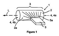
問題は、特に、長手軸線Lを有するレーザー利得媒体を含むレーザー共振器構造体を備える側面ポンプモノリシック固体レーザーによって解決される。このレーザーにおいて、レーザー共振器構造体は、直線状光路の共振キャビティを間に形成する端面を備え、端面の少なくとも一方は、その面に溶着された少なくとも部分反射のコーティングを備え、レーザー利得媒体は、ポンプ源のポンプ光を受け取る側面を備える。ポンプ光はダイオードレーザーによって発生せしめられる。また、固体レーザーは、レーザー利得媒体と接触する接触面を備える伝導冷却体を備える。固体レーザーは、長手軸線Lに対して側面の反対側に配置された反射器を備える。 The problem is solved in particular by a side-pumped monolithic solid state laser comprising a laser resonator structure comprising a laser gain medium having a longitudinal axis L. In this laser, the laser resonator structure comprises an end face that forms a resonant cavity of a linear optical path, at least one of the end faces comprises an at least partially reflective coating welded to the face, and the laser gain medium is A side surface for receiving the pump light of the pump source. The pump light is generated by a diode laser. The solid state laser also includes a conductive cooling body having a contact surface that contacts the laser gain medium. The solid state laser includes a reflector disposed on the opposite side to the longitudinal axis L.
問題は、特に、長手軸線Lを有するレーザー利得媒体を含むレーザー共振器構造体を備える側面ポンプモノリシック固体レーザーによってさらに解決される。このレーザーにおいて、レーザー共振器構造体は、直線状光路の共振キャビティを間に形成する端面を備え、端面の少なくとも一方は、特にその面に溶着された少なくとも部分反射のレーザーミラーを備え、レーザー利得媒体は、ポンプ源のポンプ光を受け取る側面を備える。ポンプ光はダイオードレーザーによって発生せしめられる。また、固体レーザーは、レーザー利得媒体と接触する接触面を備える伝導冷却体を備える。固体レーザーは、長手軸線Lに対して側面の反対側に配置された反射器を備える。レーザー利得媒体は特に低利得材料である。 The problem is further solved in particular by a side-pumped monolithic solid state laser comprising a laser resonator structure comprising a laser gain medium having a longitudinal axis L. In this laser, the laser resonator structure includes an end face that forms a resonant cavity of a linear optical path, and at least one of the end faces includes at least a partially reflecting laser mirror that is welded to the face. The medium includes a side that receives pump light from a pump source. The pump light is generated by a diode laser. The solid state laser also includes a conductive cooling body having a contact surface that contacts the laser gain medium. The solid state laser includes a reflector disposed on the opposite side to the longitudinal axis L. Laser gain media are particularly low gain materials.
問題は、特に、長手軸線Lを有するレーザー利得媒体を含むレーザー共振器構造体を備える側面ポンプモノリシック固体レーザーを作動する方法によって、さらに解決される。この方法において、ポンプ光は側面を通過してレーザー利得媒体内へ供給され、ポンプ光の一部は出射ポンプ光として反対側の側面においてレーザー利得媒体から出射し、出射ポンプ光は反射し、反射したポンプ光は、前記の反対側の側面においてレーザー利得媒体へ再び入射する。 The problem is further solved by a method of operating a side-pumped monolithic solid state laser comprising a laser resonator structure comprising a laser gain medium having a longitudinal axis L. In this method, the pump light passes through the side surface and is supplied into the laser gain medium, and part of the pump light exits from the laser gain medium on the opposite side surface as the output pump light, and the output pump light is reflected and reflected. The pump light thus incident again enters the laser gain medium on the opposite side surface.
米国特許第2007/0060917号明細書において開示されたダイオード側面ポンプ固体レーザーは、低強度あるいは低品質のレーザー光を発生させる。一方、非常に効率的に生物組織を切除するにはレーザー光はある程度のレベルの強度を必要とすることが判明している。さらに、ダイオード側面ポンプ固体レーザーは、フラッシュランプポンプ固体レーザーよりも小さいパルスエネルギーを放射することが、知られている。本発明に係る側面ポンプモノリシック固体レーザーは、レーザー光の強度・ビームの質をそれぞれ改良するいくつかの技術的特徴を使用する。まず、7.5mm2未満の断面積を有するレーザー利得媒体が使用される。断面積は、レーザー伝達方向に対して直角の、また平面レーザーミラーに関してはこれに平行のレーザー利得媒体内部の表面積である。レーザー利得媒体が、円形又は楕円形の断面を持つロッドの形状を持つ場合、ロッドが、3mm以下、好ましくは2mm以下、最も好ましくは1mm以下の直径を持つことを意味する。このように小さい直径又は小さい断面積を有するロッドの利点は、レーザー発振を開始するために必要とされる一定のパワー密度をレーザー利得媒体内で得るために必要なポンプパワーが小さいことである。さらに、このように小さい断面積を持つレーザーロッドは、レーザーキャビティ内部の開口のように作用して、より高い横断レーザーモードの損失を誘発し、あるいはレーザー光の質を改良する。小さい断面積のロッドを使用するだけで、レーザー利得媒体内部で充分なパワー密度を生成でき、それによってポンプ光が半導体レーザーによって発生せしめられる。レーザーロッドの直径が4mmであると仮定すると、断面積は約12.5mm2に増大し、3mmロッドの断面積の約2倍となる。4mmロッドは、同じパワー密度を得るためには3mmロッドの約2倍のポンプパワーが必要である。従って、レーザー利得媒体の断面積を7.5mm2に制限することは非常に重要な利点である。好ましい実施形態において、レーザー利得媒体内でのダイオードレーザーのポンプパワーは、20から500W/mm3の間である。好ましい実施形態において、キャビティ内(レーザー活性媒体内)のレーザー強度は、5kW/cm2から10MW/cm2の間であり、より好ましくは10から100kW/cm2の間である。 The diode side-pumped solid state laser disclosed in US 2007/0060917 generates low intensity or low quality laser light. On the other hand, it has been found that laser light requires a certain level of intensity to excise biological tissue very efficiently. Furthermore, diode side pump solid state lasers are known to emit less pulse energy than flash lamp pump solid state lasers. The side-pumped monolithic solid state laser according to the present invention uses several technical features that improve the laser light intensity and beam quality, respectively. First, a laser gain medium having a cross-sectional area of less than 7.5 mm 2 is used. The cross-sectional area is the surface area inside the laser gain medium perpendicular to the laser transmission direction and parallel to a planar laser mirror. If the laser gain medium has the shape of a rod with a circular or elliptical cross section, it means that the rod has a diameter of 3 mm or less, preferably 2 mm or less, most preferably 1 mm or less. The advantage of a rod having such a small diameter or small cross-sectional area is that the pump power required to obtain the constant power density required in order to start lasing in the laser gain medium is small. Furthermore, a laser rod with such a small cross-sectional area acts like an opening inside the laser cavity, inducing loss of higher transverse laser modes or improving the quality of the laser light. By simply using a small cross-section rod, a sufficient power density can be generated inside the laser gain medium, whereby the pump light is generated by the semiconductor laser. Assuming that the laser rod diameter is 4 mm, the cross-sectional area increases to about 12.5 mm 2, which is about twice the cross-sectional area of the 3 mm rod. A 4 mm rod requires about twice as much pump power as a 3 mm rod to achieve the same power density. Therefore, limiting the cross-sectional area of the laser gain medium to 7.5 mm 2 is a very important advantage. In a preferred embodiment, the pump power of the diode laser in the laser gain medium is between 20 and 500 W / mm 3 . In a preferred embodiment, the laser intensity in the cavity (in the laser active medium) is between 5 kW / cm 2 and 10 MW / cm 2 , more preferably between 10 and 100 kW / cm 2 .
レーザーの効率を向上させるさらに有利な措置は、レーザーの外部結合のパーセンテージを最適化することである。レーザー利得媒体の誘導放出断面積あるいは利得が小さければそれだけ、レーザーを効果的に作動させるためにはレーザーの外部結合のパーセンテージを小さくなければならない。これは、レーザーキャビティ内部に高い強度を持つことと同じであり、レーザー発振を開始するのに有利である。従って、レーザーキャビティ内部で高い強度を持つ低誘導放出断面のレーザー利得媒体を持つレーザーを作動することが有利である。 A further advantageous measure to improve the efficiency of the laser is to optimize the percentage of laser external coupling. The smaller the stimulated emission cross-section or gain of the laser gain medium, the smaller the laser outcoupling percentage must be in order for the laser to operate effectively. This is the same as having a high intensity inside the laser cavity, which is advantageous for starting laser oscillation. Therefore, it is advantageous to operate a laser with a laser gain medium with a low stimulated emission cross section with high intensity inside the laser cavity.
レーザー利得媒体内の強度を増大するさらに有利な措置は、反射率が92.5%から99%の範囲の出力カプラを使用することである。レーザー利得媒体内の強度を増大するさらに有利な措置は、キャビティ損失を減少させることである。離散的レーザーキャビティを使用する米国特許第2007/0060917号明細書に開示されるような固体レーザーの不利点は、反射によるレーザー利得媒体から空気へ及び空気からレーザーミラーへの媒体遷移及びこの遷移におけるレーザー光の吸収損失のために光学的損失が生じることである。使用されるレーザー媒体は低利得レーザー材料なので、このような付加的損失は、既知のレーザーシステムの効率のよい作動を妨げる。特に1700nmから3200nmの中赤外(MIR)波長領域において作動するレーザーキャビティの別の不利点は、レーザー利得媒体とレーザーミラーとの間のダスト又は湿った空気が、レーザーシステムの効率を著しく低下させ、又は放射されたレーザー光の強力な水吸収によってレーザーキャビティのレーザー光の放射をほとんど停止することである。これにより、さらに損失が生じて、レーザー利得媒体内の強度がさらに減少する。 A further advantageous measure to increase the intensity in the laser gain medium is to use an output coupler with a reflectivity in the range of 92.5% to 99%. A further advantageous measure to increase the intensity in the laser gain medium is to reduce the cavity loss. The disadvantage of solid state lasers as disclosed in US 2007/0060917 using discrete laser cavities is the reflection of the laser gain medium to air and air to laser mirror medium transition and the transition in this transition An optical loss occurs due to an absorption loss of laser light. Because the laser medium used is a low gain laser material, such additional losses prevent the efficient operation of known laser systems. Another disadvantage of laser cavities, particularly operating in the mid-infrared (MIR) wavelength region of 1700 nm to 3200 nm, is that dust or moist air between the laser gain medium and the laser mirror significantly reduces the efficiency of the laser system. Or by substantially stopping the emission of the laser light in the laser cavity by strong water absorption of the emitted laser light. This causes further losses and further reduces the intensity in the laser gain medium.
レーザー性能を改良するさらに有利な措置は、レーザー利得媒体の温度を制御することである。小さい直径のレーザーロッドは、より良い表面積対体積比を示すので、より効率よく冷却又は加熱でき、それによって、レーザービームの質の熱誘起歪みを減少する。熱性能が改良されることによるさらなる利点は、出力パワーの増大及び光−光効率(optical to optical efficiency)の向上である。 A further advantageous measure to improve the laser performance is to control the temperature of the laser gain medium. Small diameter laser rods exhibit a better surface area to volume ratio and can be cooled or heated more efficiently, thereby reducing thermally induced distortion of the quality of the laser beam. A further advantage of improved thermal performance is increased output power and optical to optical efficiency.
レーザー出力ビームの質を最適化するさらに有利な措置は、レーザー活性利得媒体を対称に冷却することである。国際公開第2004/034523号のレーザー利得媒体は対称に冷却されないため、ビームプロファイルが均質ではなく、そのため、ビームパラメータの積M2が不適当であり、集束の能力が低くなる。従って、本発明に係るレーザー活性利得媒体の対称冷却は、ビームプロファイルを均質にし、熱レンズを活性媒体の長手軸線に対して対称に且つ同一線上にする。これによって、レーザーは常にこの軸線に沿って振動する。これは、ポンプパワー、繰返し率及びデューティサイクルなどの幅広い範囲のパラメータについて安定した作動を保証するために必要な特徴である。 A further advantageous measure to optimize the quality of the laser output beam is to cool the laser active gain medium symmetrically. Since the laser gain medium of WO 2004/034523 is not cooled symmetrically, the beam profile is not homogeneous, so the beam parameter product M 2 is inadequate and the focusing ability is low. Thus, the symmetrical cooling of the laser active gain medium according to the invention makes the beam profile homogeneous and makes the thermal lens symmetrical and collinear with respect to the longitudinal axis of the active medium. This always causes the laser to oscillate along this axis. This is a necessary feature to ensure stable operation over a wide range of parameters such as pump power, repetition rate and duty cycle.
本発明に係る固体レーザーのさらなる利点は製造コストが低く且つほとんど保守が必要ないことである。このことは、市場での受入れを強力に改善する。この利点は、必要な光学素子の数及び/又は調整可能な光学素子又はレーザーキャビティの数を減らすことによって得られる。特に、手持ち又は可動式のレーザー式医療装置及び非医療装置において、調整可能な光学素子又はレーザーキャビティは市場の失敗及び経費の掛かる製品回収又は少なくとも高い保守コストの原因になってきた。本発明に係る固体レーザーは、衝撃及び振動に非常に強く、且つ、温度、湿度など環境条件の急激な変化の後でも安定しており、レーザー式医療装置に関して法律及び規則が求める非常に安定し一貫したレーザー出力パワーを保証する。従来の方法によって生産されたレーザーの設計は、荒い扱いに損傷しやすく、通常、自動的に調整から外れる。さらに、温度、機械的応力(衝撃、振動)、レンズ上のダストなどによりレーザー出力パワーの低下が生じる可能性がある。この種の装置は、定期的に修理し、レンズを磨き、レーザーキャビティを整列し直さなければならず、高い保守コストを生じる。 A further advantage of the solid state laser according to the present invention is that it is low in manufacturing cost and requires little maintenance. This strongly improves market acceptance. This advantage is obtained by reducing the number of optical elements required and / or the number of adjustable optical elements or laser cavities. In particular, in hand-held or mobile laser medical and non-medical devices, adjustable optical elements or laser cavities have caused market failures and costly product recovery or at least high maintenance costs. The solid-state laser according to the present invention is extremely resistant to shock and vibration, and is stable even after abrupt changes in environmental conditions such as temperature and humidity, and is very stable as required by laws and regulations regarding laser medical devices. Ensures consistent laser output power. Laser designs produced by conventional methods are susceptible to rough handling and are usually automatically out of adjustment. Further, the laser output power may be reduced due to temperature, mechanical stress (impact, vibration), dust on the lens, and the like. This type of equipment must be regularly repaired, the lens polished, and the laser cavity realigned, resulting in high maintenance costs.
本発明に係る固体レーザーのさらなる利点は、非常に効率がよく且つ短いレーザーキャビティのおかげで、設計を非常に小型化できることである。これによって、過去には高パワーの固体レーザーを組み込めなかった装置部品に固体レーザーを実装できる。1つの例は、米国特許第7118563号明細書において開示されるようないわゆる自給式又は手持ち無線装置における例えば最高5Wの中赤外固体レーザーの実装である。今日、この種の装置には、近赤外(780〜1400nm)のダイオードレーザーしか使用できない。本発明の1つの利点は、電池式の自給式装置が中赤外固体レーザーを備えることができることである。さらに、この種の装置は、例えば1kg未満などに軽量化されうる。より小さく且つ電力消費がより少ないレーザーを備える別の新しい装置を組み立てることができる。(1)電源、冷却ユニット及び最終的には制御ユニットを収容する卓上部分と、(2)固体レーザー、ビーム成形光学素子、ビーム偏向手段及び(おそらく)制御ユニットを収容する手持ちユニットとから成る装置を想定することさえできる。手持ちユニットは、保守のために取外し可能にされ、小さな軽量パッケージにして装置のメーカーへ送ることができる。メーカーへ装置を送る前に、装置の所有者はメーカーに連絡して、整備のために通常郵便で自身の手持ちユニットを送り返す前に仮の手持ちユニットの提供を受けることができる。正確な手順は、以下の通りとなる。a)整備のために、ベースステーションは、整備時期が近いこと、及び手持ちユニット又はハンドピースを一時的に交換するには使用者が装置のメーカーに連絡する必要があることを使用者に通知できる。b)装置の所有者又は使用者は、装置の販売店又はメーカーに口頭又は文書でメッセージを送る。c)装置の販売店又はメーカーは一時的な交換用の手持ちユニット又はハンドピースを小包で送る。d)装置の所有者又は使用者は、簡易なプラグコネクタなので非常に短時間で手持ちユニットを交換するだけであり、装置の停止時間はない。e)小包配送業者は、手持ちユニット又はハンドピースを整備のために整備センター又は装置のメーカーへ持って行き、ここで、装置は修理されて整備される。f)整備手順が完了した後、手持ちユニット又はハンドピースは装置の所有者又は使用者へ送り返される。g)装置の所有者又は使用者は再び手持ちユニット又はハンドピースを交換して、仮の手持ちユニット又はハンドピースを送り返す。これ以上費用の掛かる整備員の出張の必要はなく、また、壊れやすいレンズを含む重い装置のこれ以上費用の掛かる発送の必要はない。経費がかさむ地方の整備センターはもはや必要ない。使用者は、整備員のための部屋を確保したり、装置が修理されるまで待ったりする必要はない。これに加えて、他の機能(パルスエネルギー、波長、付加的測定)を持つ手持ち装置又は治療最適化手持ち装置をベースステーションに取り付けることができる。これら全ての利点によって、製品は、非常に経済的になり、顧客を満足させる。また、上記の全ての利点は自給式装置にとっても有効であり、卓上ユニット/ベースステーションが必要とされない。 A further advantage of the solid state laser according to the invention is that the design can be made very compact, thanks to a very efficient and short laser cavity. As a result, it is possible to mount a solid-state laser on apparatus parts that could not incorporate a high-power solid-state laser in the past. One example is the implementation of, for example, up to 5 W of mid-infrared solid-state lasers in so-called self-contained or handheld radio devices as disclosed in US Pat. No. 7,118,563. Today, only near-infrared (780-1400 nm) diode lasers can be used in this type of device. One advantage of the present invention is that a battery powered self-contained device can include a mid-infrared solid state laser. Furthermore, this type of device can be reduced in weight, for example to less than 1 kg. Another new device with a smaller and less power consuming laser can be assembled. An apparatus comprising: (1) a desktop part containing a power supply, a cooling unit and finally a control unit; and (2) a solid state laser, beam shaping optics, beam deflection means and (possibly) a handheld unit containing the control unit. Can even be assumed. The handheld unit can be removed for maintenance and sent to the device manufacturer in a small lightweight package. Before sending the device to the manufacturer, the device owner can contact the manufacturer and receive provisional hand-held units before sending them back by regular mail for service. The exact procedure is as follows. a) For maintenance, the base station can inform the user that it is almost time to service and that the user must contact the manufacturer of the device to temporarily replace the handheld unit or handpiece. . b) The device owner or user sends a message verbally or in writing to the device retailer or manufacturer. c) The retailer or manufacturer of the device sends a temporary replacement handheld unit or handpiece in a parcel. d) Since the device owner or user simply replaces the handheld unit in a very short time because the plug connector is simple, there is no device downtime. e) The parcel delivery company takes the handheld unit or handpiece to the maintenance center or equipment manufacturer for maintenance, where the equipment is repaired and serviced. f) After the maintenance procedure is completed, the handheld unit or handpiece is sent back to the owner or user of the device. g) The device owner or user again replaces the handheld unit or handpiece and sends back the temporary handheld unit or handpiece. There is no need for more costly mechanic trips and no more expensive shipping of heavy equipment containing fragile lenses. There is no longer a need for costly local maintenance centers. The user does not need to reserve a room for maintenance personnel or wait for the device to be repaired. In addition, handheld devices with other functions (pulse energy, wavelength, additional measurements) or treatment optimized handheld devices can be attached to the base station. All these advantages make the product very economical and satisfy customers. All of the above advantages are also valid for self-contained devices, and no desktop unit / base station is required.
別の有利な実施形態において、ポンプ光は、レーザー利得媒体2においてポンプ光がほぼ均質に分布するように案内される。最も有利なのは、これがレーザー利得媒体の長手軸線に対して側面の反対側に配置されたポンプ光反射器によって得られることである。この配列は、側面からレーザー利得媒体へ入射するポンプ光が、レーザー利得媒体を横切り、レーザー利得媒体から出射し、ポンプ光反射器によって反射し、反射した光が再びレーザー利得媒体に入射できるようにする。この実施形態は、レーザー利得媒体内において均質な配光を生成する。このような均質な配光の利点は、その結果、従来のシステムに比べてずっと優れたレーザーモードが得られることである。このレーザーモードは、非常に集束性の高いレーザービームの鍵となる1から25の範囲のビームパラメータの積M2を持つことができる。
In another advantageous embodiment, the pump light is guided in the
小さい断面積のレーザー利得媒体の別の利点は、レーザービームを小さい直径に集束できることである。レーザー利得媒体の断面積がもっと大きい既知のフラッシュランプポンプレーザー又はダイオードポンプレーザーはレーザービームを300〜500μmに集束できる。本発明に係る固体レーザーに使用されるレーザー利得媒体は、レーザービームを約100〜250μmに集束できる。これによって、焦点におけるレーザービームの強度を増大できる。 Another advantage of a small cross-sectional laser gain medium is that the laser beam can be focused to a small diameter. Known flash lamp pump lasers or diode pump lasers with a larger cross-sectional area of the laser gain medium can focus the laser beam to 300-500 μm. The laser gain medium used in the solid-state laser according to the present invention can focus the laser beam to about 100 to 250 μm. This can increase the intensity of the laser beam at the focal point.
本発明に係る固体レーザーのさらなる利点は、このように小さい断面積のレーザービームが、薄い従って安価な光ファイバーを通して非常に効率よく伝送されうることである。本発明のさらなる利点は、レーザービームの質が良ければそれだけ効率よくファイバー内へ内部結合して、損失が小さくなるので、ファイバーへのレーザービームの伝送の効率がより良いことである。 A further advantage of the solid state laser according to the invention is that such a small cross-sectional laser beam can be transmitted very efficiently through a thin and therefore inexpensive optical fiber. A further advantage of the present invention is that the better the quality of the laser beam, the more efficiently it is internally coupled into the fiber and the loss is reduced, so that the transmission of the laser beam into the fiber is better.
本発明に係る固体レーザーのさらなる利点は、例えばレーザーミラー又はフラッシュランプなど調整可能な光学素子を含まないことである。従って、本発明に係る固体レーザーは、衝撃によって生じる調整外れ、振動又は熱効果によって時間の経過に伴って生じる調整外れに対して強い。さらなる利点は、固体レーザーが、フラッシュランプについて典型的な時間の経過に伴うパワー損失を克服することである。 A further advantage of the solid state laser according to the invention is that it does not contain adjustable optical elements such as laser mirrors or flash lamps. Therefore, the solid-state laser according to the present invention is strong against an out-of-regulation caused by an impact and an out-of-adjustment caused with the passage of time due to vibration or a thermal effect. A further advantage is that the solid state laser overcomes the power loss over time typical for flashlamps.
本発明に係る固体レーザーのさらなる利点は、保守費用が低いことである。レーザー式医療装置に関する法律及び規則があるので、光出力パワーの変化は小さい範囲でしか許容されない。従って、既知の固体レーザーは、前記の法律及び規則を遵守するために、定期的に費用の掛かる保守を必要とするかまた複雑な制御機構を必要とする。 A further advantage of the solid state laser according to the invention is that it is low in maintenance costs. Due to laws and regulations concerning laser medical devices, changes in optical output power are only allowed to a small extent. Thus, known solid state lasers require regular expensive maintenance or complex control mechanisms to comply with the above laws and regulations.
好ましい実施形態において、本発明は、医療分野において使用されるレーザー光を発生させるのに適する、特に硬組織を含む生物組織を治療、切断又は切除するのに適するレーザー装置を提供する。レーザー装置及び生物組織の治療又は切除に関する背景情報は、国際公開第2006/111526号、第2006/111200号、第2006/111199号、第2006/111429号及び第2008/049903号において開示され、その全てが参照により本明細書に組み込まれる。好ましい実施形態において、本発明に係るレーザー装置は、硬組織を含む生物組織の治療、切断又は切除に使用される。最も有利な生物組織の切除は、1μsから15μsの間のパルス長及び103W/mm2から108W/mm2の間の強度を有するレーザーパルスを使って得られることが判明している。このようなレーザーパルスは、非常に効率の良い生物組織の切除を可能にし、例えば隣接する生物組織の変性、凝固、炭化などの熱損傷を減少させるなど、破壊を減少させる。効率よく生物組織を切除するにはある程度のレベルの強度が必要であることと、ある程度のレベルの強度は高いパルスエネルギー以上に重要であることとが判明している。また、長い持続時間のパルスによって得られる高いパルスエネルギーのパルスは、たとえば軟組織の場合で103〜106W/mm2、硬組織の場合で105〜108W/mm2の特定の強度を有するパルスよりもずっと効率が低いことが判明している。従って、103から108W/mm2の間の強度を有するレーザー光を発生させることが、生物組織の切除又は切断にとって最も好ましく、レーザー光のパルス長は1μsから15μsの間が最も好ましく、15μsから200μsの範囲はこれよりも好ましくない。1μsよりも短いパルス、例えばQスイッチレーザー又はOPOレーザーによって生成されるパルスは、衝撃波によって機械的に組織を破壊して、細胞をその自然の結合から引き裂く。生物組織など標的上で103から108W/mm2の間の強度のレーザー光を得るために、標的に衝突するレーザー光のサイズを、ビームシェイピングを用いて特にレンズを用いることによって成形できる。 In a preferred embodiment, the present invention provides a laser apparatus suitable for generating laser light used in the medical field, particularly suitable for treating, cutting or ablating biological tissue including hard tissue. Background information on laser devices and treatment or excision of biological tissue is disclosed in WO 2006/111526, 2006/111200, 2006/111199, 2006/111429 and 2008/049903, All are hereby incorporated by reference. In a preferred embodiment, the laser device according to the present invention is used for treatment, cutting or excision of biological tissue including hard tissue. It has been found that the most advantageous biological tissue ablation is obtained using laser pulses having a pulse length between 1 μs and 15 μs and an intensity between 10 3 W / mm 2 and 10 8 W / mm 2 . . Such laser pulses allow for highly efficient excision of biological tissue and reduce destruction, for example, reducing thermal damage such as denaturation, coagulation, and charring of adjacent biological tissue. It has been found that a certain level of intensity is necessary for efficient excision of biological tissue, and that a certain level of intensity is more important than high pulse energy. Also, high pulse energy pulses obtained with long duration pulses have specific intensities of, for example, 10 3 to 10 6 W / mm 2 in the case of soft tissue and 10 5 to 10 8 W / mm 2 in the case of hard tissue. It has been found to be much less efficient than a pulse with Therefore, it is most preferable to generate a laser beam having an intensity between 10 3 and 10 8 W / mm 2 for excision or cutting of biological tissue, and the pulse length of the laser beam is most preferably between 1 μs and 15 μs, The range of 15 μs to 200 μs is less preferred. Pulses shorter than 1 μs, such as those generated by Q-switched lasers or OPO lasers, mechanically disrupt tissue by shock waves, tearing cells from their natural connections. In order to obtain a laser beam with an intensity between 10 3 and 10 8 W / mm 2 on a target such as a biological tissue, the size of the laser beam impinging on the target can be shaped using beam shaping, in particular by using a lens. .
本発明の1つの態様によれば、生物組織を切断又は切除するのに適する固体レーザーと、固体レーザーを備える器具とが開示される。固体レーザーは、光学キャビティと、光学キャビティ内に配置される利得媒体と、利得媒体を光ポンプしてレーザー光を発生させるように光学的に整列された半導体レーザーとを備え、発生したレーザー光は、生物組織を切断して切除するのに適する波長及び強度を有する。 According to one aspect of the present invention, a solid state laser suitable for cutting or excising biological tissue and an instrument comprising a solid state laser are disclosed. The solid state laser comprises an optical cavity, a gain medium disposed within the optical cavity, and a semiconductor laser optically aligned to optically pump the gain medium to generate laser light, the generated laser light being It has a wavelength and intensity suitable for cutting and excising biological tissue.
本発明の1つの態様によれば、利得媒体、半導体レーザー及び光学キャビティを用意するステップと、半導体レーザーを光学的に整列させて利得媒体をポンプするように利得媒体及び半導体レーザーを光学キャビティ内に配置するステップと、半導体レーザーを作動させて、光学的に利得媒体をポンプしてレーザー光を発生させるステップと、レーザー光を軟組織、中硬組織又は硬組織などの生物組織へ向けて、生物組織を切断又は切除するステップとを含む、硬組織を含む生物組織を切断又は切除する方法が開示される。 According to one aspect of the invention, providing a gain medium, a semiconductor laser, and an optical cavity, and placing the gain medium and the semiconductor laser in the optical cavity to optically align the semiconductor laser to pump the gain medium. Placing, operating a semiconductor laser, optically pumping the gain medium to generate laser light, directing the laser light to a biological tissue such as soft tissue, medium-hard tissue or hard tissue, A method of cutting or excising biological tissue, including hard tissue, comprising: cutting or excising the tissue.
1つの実施形態において、レーザービームのパルス幅、パルス波形、繰返し率、パルス強度及びパルスエネルギーのうちの少なくとも1つを調整でき、それによって、生物組織に作られる個々の切断又は孔の特徴及びパルス当たりの生物組織の切除深さを調整できるようにする。 In one embodiment, at least one of the pulse width, pulse waveform, repetition rate, pulse intensity, and pulse energy of the laser beam can be adjusted, thereby enabling individual cutting or hole features and pulses made in the biological tissue. It is possible to adjust the excision depth of the living tissue.
生物組織を治療又は切除するレーザーは1700nmから3200nmの間の波長を有する。最も好ましくは、約2950nmの波長が使用される。なぜならば、この波長がMIR(中赤外)領域の水吸収スペクトルにおいて主要な極大だからである。 Lasers that treat or ablate biological tissue have a wavelength between 1700 nm and 3200 nm. Most preferably, a wavelength of about 2950 nm is used. This is because this wavelength is the main maximum in the water absorption spectrum in the MIR (mid-infrared) region.
本発明に係る固体レーザーは、好ましくは0.5mmから2.5mmの間の直径、より好ましくは0.5mmから1mmの間の直径を有するレーザービームを発生させる。 The solid state laser according to the present invention preferably generates a laser beam having a diameter between 0.5 mm and 2.5 mm, more preferably between 0.5 mm and 1 mm.
このような固体レーザーは、1μsから500μsの間、特に1μsから200μsの間、最も好ましくは1μsから15μsの間のパルス時間幅を有することが好ましい。 Such solid state lasers preferably have a pulse duration between 1 μs and 500 μs, in particular between 1 μs and 200 μs, most preferably between 1 μs and 15 μs.
このような固体レーザーは、0.1mJから100Jの間、特に1mJから5Jの間のレーザーパルスエネルギーを有する。 Such solid state lasers have a laser pulse energy between 0.1 mJ and 100 J, in particular between 1 mJ and 5 J.
このような固体レーザーは、スポットに焦点を合わせることができ、1W/mm2から108W/mm2の間、特に103W/mm2から107W/mm2の間のレーザー放射強度を有する。 Such a solid-state laser can focus on the spot, and the laser radiation intensity between 1 W / mm 2 and 10 8 W / mm 2 , in particular between 10 3 W / mm 2 and 10 7 W / mm 2. Have
結晶の重要な設計パラメータは、ポンプパワー及び結晶直径であり、重要なレーザー材料パラメータは、誘導放出断面積、寿命及び光子エネルギーである。 The important design parameters of the crystal are pump power and crystal diameter, and the important laser material parameters are stimulated emission cross section, lifetime and photon energy.
レーザー作用にとって、レーザー活性材料にどのようにエネルギーが供給されるかは重要ではない。すなわち、ポンプ光が側面から入るのか、同一直線上にあるのか、又はポンプがレーザーダイオードかフラッシュランプかなどは重要ではない。本発明の出発点は、レーザー活性材料がエネルギーで満たされ、より明確に言うとすでにレーザーダイオードによってポンプされているということである。Er:YAGの場合、このことは、約980nmのポンプ光がすでに結晶に入射しており、合計供給エネルギーがE_ポンプであることを意味し、これがレーザー活性イオンへ伝達される。このプロセスにおいて、エネルギーは失われ、レーザー作用のために下記の量だけが利用できる。E_蓄積=E_ポンプ×(波長_ポンプ/波長_レーザー)=(例えばEr:YAGの場合)E_ポンプ×980/2940=0.33×E_ポンプ。 For laser action, it is not important how the energy is supplied to the laser active material. That is, it does not matter whether the pump light enters from the side, is collinear, or whether the pump is a laser diode or a flash lamp. The starting point of the present invention is that the laser active material is filled with energy and more specifically already pumped by the laser diode. In the case of Er: YAG, this means that about 980 nm of pump light is already incident on the crystal and the total supply energy is E_pump, which is transmitted to the laser active ions. In this process, energy is lost and only the following quantities are available for laser action. E_accumulation = E_pump × (wavelength_pump / wavelength_laser) = (for example Er: YAG) E_pump × 980/2940 = 0.33 × E_pump.
レーザーの重要な断面Aは、レーザー軸線に対して直角であり(この場合にはレーザー結晶端面)、直径dに正比例する。 The important cross section A of the laser is perpendicular to the laser axis (in this case the laser crystal end face) and is directly proportional to the diameter d.
材料の観点から言うと、誘導放出断面積、光子エネルギー及びレーザー遷移の寿命が重要である。寿命は、結晶のポンピングにとって重要である。なぜならば、レーザー閾値に達するために結晶内へエネルギーを取り込まなければならないからである。レーザー作用が開始されるとき、レーザー活性イオンの寿命は、外部結合及びその他のキャビティパラメータによって決まり、もはや上位レーザーレベルの寿命だけで決まらない。焦点が状況に置かれるので、エネルギーがすでに結晶内部にある場合、寿命を無視できる。この状況は、レーザー結晶がポンプされた後に増幅パルスが送られるレーザー増幅器と非常に似ている。 From a material standpoint, stimulated emission cross section, photon energy and laser transition lifetime are important. Lifetime is important for crystal pumping. This is because energy must be incorporated into the crystal to reach the laser threshold. When laser action is initiated, the lifetime of the laser active ions is determined by external coupling and other cavity parameters, and is no longer determined solely by the upper laser level lifetime. Since the focus is on the situation, the lifetime can be ignored if the energy is already inside the crystal. This situation is very similar to a laser amplifier in which an amplification pulse is sent after the laser crystal is pumped.
従って、レーザー遷移の光子エネルギー及び誘導放出断面積のみが材料パラメータとして残る。光子エネルギーは、上位レーザーレベルと下位レーザーレベルとの間の差であり、誘導放出断面積は、1つの光子が別のレーザー光子の放射を誘導するために通過しなければならない1つのレーザー活性イオンの周りの面積である。 Therefore, only the photon energy of the laser transition and the stimulated emission cross section remain as material parameters. The photon energy is the difference between the upper and lower laser levels, and the stimulated emission cross section is one laser active ion that one photon must pass to induce the emission of another laser photon. Is the area around.
レーザー増幅器において、飽和フルエンスが主要な設計パラメータである。このパラメータは、レーザー光子を供給する準備ができた活性レーザーイオンを結晶面積A全体に充満させるために結晶内へポンピングされるべきエネルギーを定義する。言い換えると、結晶内へ入る各光子は、別の光子の放射を誘導する可能性が高い。 In laser amplifiers, saturation fluence is the main design parameter. This parameter defines the energy that should be pumped into the crystal to fill the entire crystal area A with active laser ions ready to supply laser photons. In other words, each photon entering the crystal is likely to induce the emission of another photon.

光子エネルギーはレーザー波長によって決定され、誘導放出断面積が小さければ、それだけ式全体は大きくなる。右側を最大にするには、より大きいエネルギーを結晶内へポンピングする必要があるか、若しくは結晶の直径dを小さくすることによって面積Aを小さくするか又は同時に両方を行う必要がある。 The photon energy is determined by the laser wavelength. The smaller the stimulated emission cross section, the larger the overall equation. To maximize the right side, it is necessary to pump more energy into the crystal, or to reduce the area A by reducing the crystal diameter d, or both at the same time.
全体的に、低放出断面を持つレーザー材料は、小さい直径のレーザー結晶を非常に強くポンプすることによってしか作動されない。 Overall, laser materials with a low emission cross section can only be operated by pumping a small diameter laser crystal very strongly.
側面を通過してレーザー利得媒体にポンプ光が供給され、ポンプ光の30〜70%好ましくは30%〜50%が出射レーザー光として反対側の側面においてレーザー利得媒体から出射し、出射ポンプ光が反射器によって反射されて、反射ポンプ光が前記の反対側側面においてレーザー利得媒体へ再び入射するという実施形態は有利である。利得材料の吸収ピークの波長とは異なる特定の波長を用いると、入射ポンプ光がレーザー利得媒体によって部分的にしか吸収されず、従って、入射ポンプ光の30%〜70%好ましくは30%〜50%の量がレーザー利得媒体から出射し、反射してレーザー利得媒体に戻され、レーザー利得媒体において、さらに合計で50〜91%好ましくは75%〜91%吸収されるという利点を有する。従って、レーザー利得媒体内で均等の配光が得られ、その結果、放射されたレーザービーム内に均等なガウス分布状のエネルギー分布が得られる。反射器は、ほとんど入射光全部を反射する高反射係数を持つものとして実現されうる。さらに、部分的に反射させ又は散乱させて、レーザー利得材料の均等な照度を強化できる。 Pump light is supplied to the laser gain medium through the side surface, and 30 to 70%, preferably 30% to 50% of the pump light is emitted from the laser gain medium on the opposite side surface as the emitted laser light, and the emitted pump light is An embodiment in which the reflected pump light is incident again on the opposite side surface into the laser gain medium after being reflected by the reflector is advantageous. Using a specific wavelength that is different from the wavelength of the absorption peak of the gain material, the incident pump light is only partially absorbed by the laser gain medium, and therefore 30% to 70%, preferably 30% to 50% of the incident pump light. % Amount exits from the laser gain medium, is reflected back to the laser gain medium, and has the advantage of being further absorbed by the laser gain medium in a total of 50-91%, preferably 75% -91%. Therefore, a uniform light distribution is obtained in the laser gain medium, and as a result, a uniform Gaussian energy distribution is obtained in the emitted laser beam. The reflector can be realized as having a high reflection coefficient that reflects almost all of the incident light. Furthermore, it can be partially reflected or scattered to enhance the even illumination of the laser gain material.
吸収極大に対するポンプ源の波長/波長領域シフトは、結晶材料の結晶直径及びドーパント濃度によって決まり、結晶直径が吸収長に等しくなるような態様において選択される。吸収長は、レーザー材料に入射するポンプ放射の63.2%が吸収された後のレーザー材料の長さとして定義される。この尺度から、最適化されたポンプ光分布/結晶内における最適化されたより均質の照度が得られる。ポンプ光波長/波長領域が吸収極大において選択されると、ポンプ光は、例えば2mmを有する結晶において、例えば1mm吸収され、残りの結晶は照射されず、レーザービームの質を著しく低下させる。単純化された式は下記の通りである。 The wavelength / wavelength region shift of the pump source relative to the absorption maximum depends on the crystal diameter of the crystalline material and the dopant concentration and is selected in such a way that the crystal diameter is equal to the absorption length. Absorption length is defined as the length of the laser material after 63.2% of the pump radiation incident on the laser material has been absorbed. From this measure, an optimized pump light distribution / optimized more homogeneous illumination within the crystal is obtained. When the pump light wavelength / wavelength region is selected at the absorption maximum, the pump light is absorbed, for example, 1 mm in a crystal having, for example, 2 mm, and the remaining crystal is not irradiated, and the quality of the laser beam is significantly reduced. The simplified formula is as follows.
結晶の直径:X
吸収係数:α
条件:X×α=1
Crystal diameter: X
Absorption coefficient: α
Condition: X × α = 1
吸収の法則
結晶内における吸収=exp(−X×α)=exp(−1)=0.632。各レーザー材料は固有の吸収係数αを有し、αは波長によって決まるので、この式はこのポンプ形状の全てのレーザー材料に有効である。
Absorption law Absorption in crystal = exp (−X × α) = exp (−1) = 0.632. Each laser material has a unique absorption coefficient α, which depends on the wavelength, so this equation is valid for all laser materials of this pump shape.
長手軸線に平行に配置されたレーザーダイオードアレイとして実現されるポンプ源は、レーザー利得媒体にその長さに沿って分布するポンプ光を提供できるという利点を有する。ポンプ源の長さは、レーザー利得媒体の長さの少なくとも30%であることが好ましい。この実施形態は、レーザー利得材料の均等な照度を与え、充分なポンプ光エネルギーを与えて、低利得材料のレーザー作用を開始することを目的とする。 A pump source realized as a laser diode array arranged parallel to the longitudinal axis has the advantage that it can provide pump light distributed along its length in the laser gain medium. The length of the pump source is preferably at least 30% of the length of the laser gain medium. This embodiment is aimed at providing a uniform illuminance of the laser gain material and sufficient pump light energy to initiate the laser action of the low gain material.
低利得材料は、Er:YAGの誘導放出断面積すなわち3.0×10⁻²⁰cm2以下の誘導放出断面積を持つレーザー利得媒体であることを特徴とする。このレーザー利得媒体は、高い光学的効率及び電気的効率を得るために誘導放出断面積28×10-20cm2のNd:YAGなどの高利得レーザー材料が使用される高能率のレーザーシステムから本発明に係る固体レーザーを区別する。高利得材料の場合、組織治療のためにかなり多量の光が光共振器から外部結合する可能性がある。 The low gain material is characterized by being a laser gain medium having a stimulated emission cross section of Er: YAG, that is, a stimulated emission cross section of not more than 3.0 × 10 −20 cm 2 . This laser gain medium comes from a highly efficient laser system in which a high gain laser material such as Nd: YAG with a stimulated emission cross section of 28 × 10 −20 cm 2 is used to obtain high optical and electrical efficiency. Distinguish solid lasers according to the invention. For high gain materials, a significant amount of light can be externally coupled from the optical resonator for tissue treatment.
固体レーザーの丈夫な実施形態のおかげで、特に伝導冷却体によってレーザー利得媒体が取り囲まれて保持される配列のおかげで、レーザーは、少なくとも100Gという大きな力に耐えることができる。これによって、レーザーは、特別な発送手順を必要とすることなく発送できる。特に、レーザーを保守センターへ発送できるので、現場で保守作用を行う必要がない。 Thanks to the robust embodiment of the solid-state laser, the laser can withstand a force as great as at least 100 G, especially thanks to the arrangement in which the laser gain medium is surrounded and held by the conductive cooling body. This allows the laser to be shipped without the need for special shipping procedures. In particular, since the laser can be sent to the maintenance center, there is no need to perform maintenance on site.
レーザービームの質が非常に優れているので、直列に(直線状に交互に且つレーザービーム伝播軸線と同一線上に)、又はミラー、ステアミラー、レンズ及び技術上既知のその他の結合ユニットを介して複数のレーザーユニットを接続することも容易である。複数のレーザーの接続によって、最大出力パワー及び/又は平均出力パワーを増大できるが、単一レーザーユニットの要因による繰返し率も増大する。高出力パワーは、水又はヒドロキシル(OHボンド)の含有量が非常に少ない物質を処置でき、又は非常に高い衝撃波及び大きなキャビテーションバブルを生成し、又はプラズマ発生さえも可能にする。理想的には、レーザーは、ビームがコヒーレントに結合できるように位相がロックされる。 The quality of the laser beam is so excellent that it can be in series (alternately and collinearly with the laser beam propagation axis) or via mirrors, steer mirrors, lenses and other coupling units known in the art It is easy to connect a plurality of laser units. Multiple laser connections can increase the maximum output power and / or the average output power, but also increase the repetition rate due to a single laser unit factor. High output power can treat materials with very low water or hydroxyl (OH bond) content, or can produce very high shock waves and large cavitation bubbles, or even plasma generation. Ideally, the laser is phase locked so that the beam can be coherently coupled.
レーザーのモノリシック設計は、レーザー高反射反射器が直接利得媒体上に溶着され、出力カプラが利得媒体の反対側の端に直接溶着されることを特徴とする。導入されるレーザー材料が低利得なので、レーザー材料の端面に対してオフセットするレーザーミラーの配列はかなり困難である。なぜならば、レーザー材料から自由大気へその後ミラー材料へ及び逆向きへ媒体変化があるときに損失が生じるので、ほとんどレーザー発振が生じないからである。 The laser monolithic design is characterized in that the laser high-reflector reflector is welded directly onto the gain medium and the output coupler is welded directly to the opposite end of the gain medium. Since the introduced laser material has a low gain, the arrangement of the laser mirrors offset with respect to the end face of the laser material is quite difficult. This is because loss occurs when there is a medium change from the laser material to the free air, then to the mirror material, and in the opposite direction, so that almost no laser oscillation occurs.
本発明の1つの目的は、本発明に係る固体レーザーを備える治療装置によって解決される。固体レーザーはハウジングに配置され、固体レーザーの放射レーザービームは、可撓ホース内の導光素子によって手持ち装置へ向けられる。手持ち装置は、レーザービームを標的面へ向けるために、導光素子の終端部について出口ポートを備える。可撓ホースは、導光素子を備え、従って、レーザー光源と治療装置(すなわち、手持ちユニット)の分散配列を可能にし、高エネルギー出力レーザー装置は導光素子を介してその出力パワーを治療装置へ送達する。 One object of the present invention is solved by a treatment device comprising a solid state laser according to the present invention. The solid state laser is disposed in the housing, and the emitted laser beam of the solid state laser is directed to the handheld device by a light guide element in the flexible hose. The hand-held device has an exit port at the end of the light guide element for directing the laser beam to the target surface. The flexible hose includes a light guide element, thus enabling a distributed arrangement of the laser light source and the treatment device (ie, handheld unit), and the high energy output laser device passes its output power to the treatment device via the light guide element. Deliver.
固体レーザーのポンプ光は、充分なエネルギー密度を持つポンプ光を生成するために大量の電気エネルギーを必要とするので、電源は、非常に短い時間に大量の電気エネルギーを提供できなければならない。このために、非常に強力な電源、又は1つの実施形態によれば、高電流容量バッファ(high current capacity buffer)を持つ電源が必要である。この実施形態の場合、充分に長い時間にわたって連続的にバッファを充電でき且つ非常に短い時間でバッファを放電できるので、高電流電力をポンプ光源へ提供できる。 Since solid-state laser pump light requires a large amount of electrical energy to generate pump light with sufficient energy density, the power source must be able to provide a large amount of electrical energy in a very short time. This requires a very powerful power supply or, in one embodiment, a power supply with a high current capacity buffer. In this embodiment, the buffer can be continuously charged for a sufficiently long time and the buffer can be discharged in a very short time, so that high current power can be provided to the pump light source.
例えば医療分野で治療装置を使用する際、手持ち装置で利用できる加圧ガスがあると有益である。従って、1つの実施形態によれば、治療装置のハウジングは加圧ガス特に周囲圧力に対して正及び/又は負の圧力の加圧ガスを発生させる装置を備える。本明細書において使用される場合、加圧ガスは、特に空気及び例えば治療領域から酸素を取り除くことによって切除を改良し且つ/又は悪影響のない切除を保証するために使用できるプロセスガスの全ての混合物を含む。 For example, when using a treatment device in the medical field, it is beneficial to have a pressurized gas that can be used with a handheld device. Thus, according to one embodiment, the housing of the treatment device comprises a device for generating a pressurized gas, in particular a pressurized gas of positive and / or negative pressure relative to the ambient pressure. As used herein, pressurized gas is a mixture of all process gases that can be used to improve ablation and / or ensure harmless ablation, particularly by removing oxygen from, for example, air and treatment areas. including.
同様の実施形態において、ハウジングは加圧液を発生させる装置を備える。レーザービームが熱切除法によって物質を切除するので、標的領域を浄化及び/又は冷却することは有益であり、このため、手持ち装置において利用可能な液体を有することは有利である。 In a similar embodiment, the housing comprises a device that generates pressurized liquid. Since the laser beam ablates the material by thermal ablation, it is beneficial to clean and / or cool the target area, so it is advantageous to have a liquid available in the handheld device.
従って、可撓ホースは、ハウジング内の装置から手持ち装置へ加圧液を送達するダクト又は手持ち装置へ加圧ガスを供給するダクトを備える。相対正圧の加圧ガスを用いれば、例えば、特に標的面におけるレーザービームの作動領域の周りから酸素環境を排除するために治療点の周りに不活性ガスキャップ(inert gas cap)を与えることができる。相対負圧のガスを用いれば、標的面上のレーザービームの作動領域から物質を吸引できる。レーザービームは標的面から物質を切除するので、レーザーを適切に作動するには切除された物質を標的領域から取り除かなければならない。実施形態によれば、この物質は吸い取られて可撓ホース内のダクトを介して処分装置又はハウジング内の使い捨てユニットへ運ばれて、標的領域がきれいにされる。 Thus, the flexible hose comprises a duct that delivers pressurized liquid from a device in the housing to the handheld device or a duct that supplies pressurized gas to the handheld device. Using a pressurized gas of relatively positive pressure, for example, can provide an inert gas cap around the treatment point to eliminate the oxygen environment, especially from around the working area of the laser beam at the target surface. it can. If a gas having a relative negative pressure is used, the substance can be sucked from the laser beam working region on the target surface. Because the laser beam ablates material from the target surface, the ablated material must be removed from the target area for proper laser operation. According to an embodiment, this material is sucked up and conveyed via a duct in the flexible hose to a disposal device or a disposable unit in the housing to clean the target area.
ハウジングが取外し可能なコネクタ手段を備える実施形態は、治療装置の使用ごとに特に手持ち装置の使用ごとに新しい手持ち装置及び可撓ホースを使えるという利点を有する。有害な物質を伴う用途の場合、手持ち装置及び可撓ホースは汚染されて、交換する必要がある場合がある。このような実施形態は、安価な導光素子例えばシリコン酸化物を主原料とする導光素子に適し、この場合、徹底的な浄化を行うよりも手持ち装置と一緒にホース内の導光素子を処分した方が、経費が掛からない。そうでなければ、可撓ホースと一緒に手持ち装置全体を浄化又は滅菌できる。 Embodiments in which the housing is provided with removable connector means have the advantage that a new hand-held device and a flexible hose can be used for each use of the treatment device, especially for each hand-held device use. For applications involving hazardous materials, handheld devices and flexible hoses may become contaminated and need to be replaced. Such an embodiment is suitable for an inexpensive light guide element, for example, a light guide element mainly made of silicon oxide. In this case, the light guide element in the hose can be used together with the hand-held device rather than performing thorough purification. Disposal costs less. Otherwise, the entire handheld device can be cleaned or sterilized with the flexible hose.
例えばサファイア、酸化ゲルマニウム、フッ化ジルコニウム、セラミックファイバー、セラミックグラスファイバー、セレン若しくはテルル含有ファイバー、又は概してフッ化物又はセラミックスを主原料とするファイバー若しくは結晶材料を主原料とするファイバーから作られた非常に高価な導光素子がホースの中に配置される場合、導光素子を保存して手持ち装置のみを交換又は浄化することが重要である。1つの実施形態によれば、手持ち装置は取外し可能なコネクタ手段を備えて各使用後に手持ち装置を処分できるようにする。別の実施形態によれば、取外し可能なコネクタ手段はハウジングに配置され、このため、ホースと一緒に手持ち装置をハウジングから分離することが可能となる。別の実施形態においては、ホースは両端に取外し可能なコネクタを備えることができ、このため、手持ち装置及び可撓ホースが個々に分離されることが可能となる。これは、例えば、手持ち装置をオートクレーブ内で滅菌し、可撓ホースを消毒液の中に浸漬するなど異なる浄化作業を実施するのに適する。 For example, very much made from sapphire, germanium oxide, zirconium fluoride, ceramic fiber, ceramic glass fiber, selenium or tellurium-containing fiber, or fiber that is generally based on fluoride or ceramics or fiber based on crystalline materials When expensive light guide elements are placed in the hose, it is important to store the light guide elements and replace or clean only the handheld device. According to one embodiment, the handheld device comprises removable connector means so that the handheld device can be disposed of after each use. According to another embodiment, the removable connector means is arranged on the housing, so that the handheld device can be separated from the housing together with the hose. In another embodiment, the hose can be provided with a removable connector at both ends, which allows the handheld device and the flexible hose to be separated separately. This is suitable, for example, for carrying out different cleaning operations, such as sterilizing a handheld device in an autoclave and immersing a flexible hose in a disinfectant solution.
本発明によれば、手持ち装置は、レーザービームを標的面へ向けるために、導光素子の終端部について出口ポートを備える。1つの実施形態によれば、手持ち装置はビーム形成ユニット及び/又はビーム偏向ユニットを備え、このため、例えば特定のエネルギー密度分布を与えるべく、標的領域内の特定の点にレーザービームを偏向すべく、又は標的領域内において特定の移動パターンを与えるべく、導光素子によって提供されたレーザービームを形成することが可能となる。導光素子の終端部へ放射されたレーザービームは、ビーム形成ユニット及び/又は偏向ユニットへ入り、ここで処理されて、出口ポートを介して手持ち装置を離れる。 According to the invention, the handheld device comprises an exit port at the end of the light guide element for directing the laser beam to the target surface. According to one embodiment, the handheld device comprises a beam forming unit and / or a beam deflection unit, so that the laser beam is deflected to a specific point in the target area, for example to give a specific energy density distribution. Alternatively, the laser beam provided by the light guide element can be formed to give a specific movement pattern within the target area. The laser beam emitted to the end of the light guide element enters the beam forming unit and / or the deflection unit, where it is processed and leaves the hand-held device via the exit port.
治療の可能性を与えるために、手持ち装置は、さらに、音響変換器特に超音波変換器を備える。レーザーは、主に標的領域内において高温パルスを発生させることによって主に作用し、これによって物質を切除する。音響変換器(発生せしめられた音響を、案内手段を介して例えば出口ポートの先端へ向ける)を手持ち装置において利用できると、レーザーによって行われる熱切除と共に機械的エネルギーが物質の切除のために提供される。レーザー部分は周囲組織に損傷を与えてはならない重要な領域に利用し、超音波部分は、重要性の低い領域の高速除去に使用できる。 In order to provide therapeutic possibilities, the handheld device further comprises an acoustic transducer, in particular an ultrasonic transducer. The laser works primarily by generating high temperature pulses in the target area, thereby ablating material. When an acoustic transducer (directing the generated sound, for example towards the tip of the outlet port) is used in the hand-held device via the guiding means, mechanical energy is provided for material ablation along with thermal ablation performed by the laser Is done. The laser part can be used for critical areas that should not damage the surrounding tissue, and the ultrasonic part can be used for fast removal of less important areas.
いくつかの用途においては、標的領域で複数のビームを利用できると有益である。従って、1つの実施形態によれば、手持ち装置は導光素子分割ユニットを備える。分割ユニットは、導光素子を介して固体レーザーによって与えられたレーザービームを複数のレーザービームにして供給する。これは、例えば、導光素子のスプライシング、回折レンズ、マイクロレンズ、ステアミラー、合成二次曲面集光器又は逆転使用マルチファイバーコンセントレータ(inversed used multi-fiber concentrator)によって実施されうる。この実施形態の別の利点は、レーザーが標的領域へ入る媒体変化境界面において光エネルギー量が大きいため、キャビテーションバブルが生じて、標的領域において利用できるパワー密度が減少する可能性があることである。レーザービームを複数のレーザービームに分割することによって、レーザービーム当たりのパワー密度は小さくなるので、このようなキャビテーションバブルの発生の可能性を減少する。その結果、望ましくないキャビテーションにエネルギーが浪費されず、より多くのエネルギーが標的領域へ向けられる。 In some applications, it may be beneficial to have multiple beams available at the target area. Therefore, according to one embodiment, the handheld device comprises a light guide element dividing unit. The dividing unit supplies a laser beam provided by a solid-state laser through a light guide element as a plurality of laser beams. This can be done, for example, by splicing light guide elements, diffractive lenses, microlenses, steer mirrors, synthetic quadratic concentrators or inverted used multi-fiber concentrators. Another advantage of this embodiment is that the amount of light energy at the media change interface where the laser enters the target area can cause cavitation bubbles and reduce the power density available in the target area. . By dividing the laser beam into a plurality of laser beams, the power density per laser beam is reduced, thereby reducing the possibility of the occurrence of such cavitation bubbles. As a result, energy is not wasted in undesirable cavitation and more energy is directed to the target area.
治療対象の標的領域は、通常かなり小さく、操作者による治療プロセスの視覚的評価はかなり困難なので、別の実施形態によれば、手持ち装置は、光学的画像化手段を備える。この光学的画像化手段は、例えば、出口ポート又はその周りに配置されて標的領域へ向けられたCCDカメラのような画像化センサである。さらに、標的領域へ向けられて、画像を画像捕捉手段へ送る1つの導光素子を含むことができる。画像捕捉手段は手持ち装置又はハウジング内に配置され、後者の場合、可撓ホースは、取得した画像を手持ち装置からハウジングへ搬送する別の導光素子を備える。別の実施形態において、手持ち装置内に2つの光学的画像化手段が配置され、標的領域を立体的に捕捉できるようにして、治療装置の操作者に標的領域の三次元画像を提供できる。別の実施形態では、手持ち装置、特に出口ポートは、標的領域を照らす照明手段を備えることができる。 According to another embodiment, the hand-held device comprises optical imaging means, since the target area to be treated is usually quite small and the visual assessment of the treatment process by the operator is quite difficult. This optical imaging means is, for example, an imaging sensor, such as a CCD camera, arranged at or around the exit port and directed towards the target area. Furthermore, it can include one light guide element that is directed to the target area and sends the image to the image capture means. The image capture means is arranged in a handheld device or housing, in which case the flexible hose comprises another light guide element that carries the acquired image from the handheld device to the housing. In another embodiment, two optical imaging means can be placed in the handheld device to provide a three-dimensional image of the target area to the operator of the treatment device, allowing the target area to be captured in a three-dimensional manner. In another embodiment, the handheld device, in particular the exit port, can be equipped with illumination means for illuminating the target area.
別の実施形態によれば、手持ち装置は、好ましくは50kHzから5MHzの範囲の無線周波数を放射する無線周波数伝送器を備える。この実施形態では、所望の深さまで標的物質に侵入するように無線周波数を選択でき、さらなる治療が可能である。好ましくは、無線周波数伝送器は、最適化された用途固有の無線周波数を標的領域へ伝送できるように、調節可能である。さらに、無線周波数伝送器は、無線周波数を治療対象あるいは切除対象の組織へ向けるアンテナ手段を備える。レーザー部分は、周囲組織を損傷させてはならない重要な領域に使用し、無線周波数部分は、これよりも重要性の低い組織領域の高速除去に使用できる。 According to another embodiment, the handheld device comprises a radio frequency transmitter that emits radio frequencies, preferably in the range of 50 kHz to 5 MHz. In this embodiment, the radio frequency can be selected to penetrate the target material to the desired depth, allowing further treatment. Preferably, the radio frequency transmitter is adjustable so that an optimized application specific radio frequency can be transmitted to the target area. In addition, the radio frequency transmitter comprises antenna means for directing the radio frequency to the tissue to be treated or ablated. The laser part can be used for critical areas that should not damage the surrounding tissue, and the radio frequency part can be used for fast removal of less important tissue areas.
手持ち装置内に様々な装置を供給するために、可撓ホースは、ハウジング内の電源から手持ち装置へ電気エネルギーを提供する電源ケーブルを備える。 To supply various devices within the handheld device, the flexible hose includes a power cable that provides electrical energy from the power source in the housing to the handheld device.
標的領域へのレーザービームの放射を制御するために、可撓ホースが少なくとも1つのデータ伝送回線を備えると有利である。データ伝送回線は、例えば制御ユニット及び手持ち装置を制御ユニット及びハウジングと接続する。手持ち装置内の制御ユニットは、使用者との対話処理のために組み込まれ、特に、レーザーの作動を制御する制御機能を使用者に与える。ハウジング内の制御ユニットは、手持ち装置内の制御ユニットから指令を受信して、これに従ってレーザーを作動する。データ伝送回線は、個別の多数の制御回線を必要とすることなく多数の指令を伝送できるという利点を有する。 In order to control the emission of the laser beam to the target area, it is advantageous if the flexible hose comprises at least one data transmission line. The data transmission line connects, for example, the control unit and the handheld device to the control unit and the housing. A control unit in the handheld device is incorporated for interaction with the user and in particular provides the user with control functions that control the operation of the laser. The control unit in the housing receives commands from the control unit in the handheld device and activates the laser accordingly. The data transmission line has the advantage that multiple commands can be transmitted without the need for multiple separate control lines.
導光素子は単一のファイバー導光素子として実現されうる。単一のファイバー導光素子は、レーザービームの光エネルギー全体が1本のファイバー内で搬送されるので、レーザービームをファイバー内へ結合し、ファイバーからレーザービームを受け取って、標的面へビームを向けるのが容易であるという利点を有する。 The light guide element can be realized as a single fiber light guide element. A single fiber light guide element couples the laser beam into the fiber, receives the laser beam from the fiber, and directs the beam to the target surface because the entire light energy of the laser beam is carried in one fiber It has the advantage that it is easy.
別の実施形態によれば、導光素子は複数のファイバー導光素子として実現されうる。複数のファイバー導光素子は、各単一ファイバー内のエネルギー密度が減少するので、ファイバー材料に対する光学的な応力が減少し、過度な光エネルギーによるファイバーの損傷の可能性が減少するという利点を有する。さらに、各ファイバーから標的領域へ放射される光エネルギーが小さくなるので、キャビテーションバブルを発生させるリスクが減少する。各ファイバーは、固体レーザーから手持ち装置へレーザービームを搬送するという同じ機能を持つように、又は個々のファイバーが異なるタスクを実施するように構成されうる。例えば、複数のファイバー導光素子の1本のファイバーを照明目的に使用し、別のファイバーを問題の感知又は分析に使用できる。このファイバーは、標的領域の画像をハウジング内の分析モジュールへ送る。各ファイバーを同じ材料で作ることができるが、1つの実施形態においては、個々のファイバーに異なる材料を使用できる。これは、個々の波長に最適な光搬送を与えるようにファイバー材料が選択される場合、異なる波長を使用できるという利点を有する。従って、異なる波長のレーザービームを放射するように調節可能な1つの固体レーザーを持つことができる。又は各々固有の波長を放射する複数の固体レーザー、半導体レーザー又は発光ダイオードなどの光源をハウジング内に配置して、そのレーザービームを多数の個々のファイバー内に結合できる。治療対象の物質に応じて波長を調節する必要があるので、異なる波長を使用することは、より多くの物質を治療できるという利点を有する。 According to another embodiment, the light guide element may be realized as a plurality of fiber light guide elements. Multiple fiber lightguides have the advantage that the energy density within each single fiber is reduced, thus reducing the optical stress on the fiber material and reducing the possibility of fiber damage due to excessive light energy. . In addition, the light energy emitted from each fiber to the target area is reduced, reducing the risk of generating cavitation bubbles. Each fiber can be configured to have the same function of delivering a laser beam from a solid state laser to a handheld device, or so that individual fibers perform different tasks. For example, one fiber of a plurality of fiber light guide elements can be used for illumination purposes and another fiber can be used for problem sensing or analysis. This fiber sends an image of the target area to the analysis module in the housing. Each fiber can be made of the same material, but in one embodiment, different materials can be used for individual fibers. This has the advantage that different wavelengths can be used if the fiber material is selected to provide optimal light transport for the individual wavelengths. Thus, it is possible to have one solid state laser that can be adjusted to emit laser beams of different wavelengths. Alternatively, a plurality of solid state lasers, semiconductor lasers or light emitting diodes, each emitting a unique wavelength, can be placed in the housing and the laser beam can be coupled into a number of individual fibers. Since it is necessary to adjust the wavelength according to the substance to be treated, the use of different wavelengths has the advantage that more substances can be treated.
本明細書において使用される場合、ファイバーとの用語は、入射端から出射端へ1つ又は複数の波長の光を案内できる任意の種類の光導波路を意味し、導路は必ずしも直線ではない。例として、光ファイバー、中空光ファイバー、関節式連結ミラーアーム(articulated mirror arm)がある。特に、ファイバーは、可撓ホース内に配置されうるので、何かがレーザービーム内に入ったり損傷を受けたりする危険(これは、レーザービームの自由大気での伝送において生じる可能性がある)なしに、光、特に長距離の高パワーレーザー光の搬送を可能にする。 As used herein, the term fiber refers to any type of optical waveguide capable of guiding one or more wavelengths of light from the input end to the output end, and the guide is not necessarily straight. Examples are optical fibers, hollow optical fibers, articulated mirror arms. In particular, the fiber can be placed in a flexible hose, so there is no danger of anything entering the laser beam or being damaged (this can occur in the transmission of the laser beam in free air) In addition, it makes it possible to carry light, particularly high-power laser light over a long distance.
出口ポートの第一の目的は、導光素子から離れるレーザービームを標的面に向けられるようにし、それによって手持ち装置から離れられるようにすることである。前の実施形態によれば、可撓ホースは、1つの導光素子だけでなくそれ以上の供給ラインを備えることができるので、別の実施形態において、出口ポートはダクトに接続された出口開口を備える。従って、可撓ホース内に配置された様々な供給ラインは、手持ち装置の出口ポートに直接出口を備えるので、標的領域に近接する。 The primary purpose of the exit port is to allow the laser beam leaving the light guide element to be directed to the target surface, thereby leaving the handheld device. According to the previous embodiment, the flexible hose can comprise not only one light guide element but also more supply lines, so in another embodiment the outlet port has an outlet opening connected to the duct. Prepare. Thus, the various supply lines arranged in the flexible hose are close to the target area because they provide an outlet directly at the outlet port of the handheld device.
治療用には、導光素子の終端部が、少なくとも部分的に出口開口の周りに配置されると有利である。例えば、出口開口が相対負圧の加圧ガスを提供するダクトに接続される場合、放射されたレーザービームが、標的面から物質を切除した後、物質は出口開口内へ吸引されて、ダクトを介してハウジング内の廃物コンパートメントへ搬送される。一方、ダクトが、レーザービームによって切除された物質を洗い流す液体を供給すると有用であるかもしれない。 For therapeutic purposes, it is advantageous if the end of the light guide element is at least partially arranged around the outlet opening. For example, if the exit opening is connected to a duct that provides a pressurized gas of relative negative pressure, after the emitted laser beam has excised the material from the target surface, the material is sucked into the exit opening and To the waste compartment in the housing. On the other hand, it may be useful for the duct to provide a liquid to wash away the material that has been ablated by the laser beam.
出口開口が少なくとも部分的に導光素子の周りに配置される実施形態は、例えば、レーザービームの周りに制御された空気及び環境を確立でき、それによって標的領域から遊離酸素を取り除くことができるという利点を有する。高エネルギー光パルスが出口ポートから自由大気へ放射されると、イオン化効果が生じて、標的領域内に望ましくない反応生成物が発生する可能性がある。これは、標的領域を不活性ガスで覆うことによって回避できる。 Embodiments in which the exit aperture is at least partially disposed around the light guide element can, for example, establish a controlled air and environment around the laser beam, thereby removing free oxygen from the target area. Have advantages. When high energy light pulses are emitted from the exit port to the free atmosphere, ionization effects can occur and undesired reaction products can be generated in the target area. This can be avoided by covering the target area with an inert gas.
本発明の1つの目的は、さらに、本発明に係る固体レーザーを持つ手持ち装置と、手持ち装置、特に固体レーザーに電力エネルギーを供給する電源を備える卓上ユニットと、手持ち装置を卓上ユニットと接続する可撓ホースとを備える治療装置によってさらに解決される。低利得レーザー材料の独創的な使用によって、固体レーザーは、レーザービームを生成するときに大量の過剰熱を発生させる。レーザーを損傷しないようにするために、この熱を固体レーザーから取り除かなければならない。従って、固体レーザーは、本発明においてはキャビティとして実現される冷却ユニットを備える。冷却キャビティは、可撓ホース内に配置された2つの冷却液搬送管を介して、卓上ユニット内の冷却液循環システムに接続される。この実施形態によって、高エネルギーレーザービーム出力を持つ個体レーザーを手持ち装置に配置し、手持ち装置から過剰な熱を取り除いて、この熱を卓上ユニットへ搬送し、卓上ユニットに効率の高い冷却システムを配置することができる。さらに、固体レーザーは、固体レーザーを電気駆動する制御ユニットを備え、制御ユニットは、本発明によれば、レーザー放射を誘導するのに充分な電流をポンプ源へ与える1つの高電流容量バッファを備える。この電流バッファ及び熱循環システムは、高強度レーザービームを与えることができるレーザー式治療装置に、長い期間にわたって高い稼動サイクルを与える。コンタクト窓は標的面へレーザービームを送達する。通常、標的面に対してコンタクト窓の直接接触又は接近配置が可能である。治療作業を行った後、特に生物標本に関する作業を行った後、治療装置及び特にコンタクト窓を徹底的に浄化しなければならず、特に殺菌を行わなければならない。従って、コンタクト窓はこの種の化学的処置に耐えなければならず、従って、例えばMFA、PFA又はFEPなどの蛍光ポリマーとして実現される。 One object of the present invention is further to provide a hand-held device having a solid-state laser according to the present invention, a hand-held device, in particular a desktop unit comprising a power supply for supplying power energy to the solid-state laser, and a hand-held device connected to the table-top unit. It is further solved by a treatment device comprising a flexible hose. Due to the original use of low gain laser materials, solid state lasers generate a large amount of excess heat when generating the laser beam. This heat must be removed from the solid state laser to avoid damaging the laser. Thus, the solid state laser comprises a cooling unit which is realized as a cavity in the present invention. The cooling cavity is connected to a coolant circulation system in the tabletop unit via two coolant transport pipes arranged in the flexible hose. This embodiment places a solid laser with high energy laser beam output in a handheld device, removes excess heat from the handheld device, transports this heat to the tabletop unit, and places a highly efficient cooling system on the tabletop unit can do. Furthermore, the solid state laser comprises a control unit that electrically drives the solid state laser, and according to the invention, the control unit comprises a single high current capacity buffer that provides sufficient current to the pump source to induce laser radiation. . This current buffer and thermal cycling system provides a high operating cycle over a long period of time for a laser therapy device capable of providing a high intensity laser beam. The contact window delivers a laser beam to the target surface. Usually, direct contact or close proximity of the contact window to the target surface is possible. After carrying out the treatment work, in particular after working on the biological specimen, the treatment device and in particular the contact window must be thoroughly cleaned and in particular sterilized. Thus, the contact window must withstand this type of chemical treatment and is thus realized as a fluorescent polymer, for example MFA, PFA or FEP.
さらに、本発明の目的は、手持ち装置のみを備える治療装置の別の実施形態によって解決される。手持ち装置は、エネルギー蓄積手段を備え、冷却ユニットは固体冷却装置として実現される。手持ち装置の場合、通常、高い作動デューティサイクルは要求されず、長期の連続的作動も要求されない。従って、受動的冷却ユニットが個体レーザーに取り付けられれば充分であり、この冷却ユニットは、過剰な熱を引き取って、これをレーザー装置から取り除いて、レーザー装置を正常な作動パラメータの範囲内に維持する。治療作動の繰返し率は卓上ユニット式システムよりも小さいので、エネルギー蓄積はリチウムイオン二次電池などの充電式電池で可能である。 Furthermore, the object of the present invention is solved by another embodiment of a treatment device comprising only a handheld device. The handheld device comprises energy storage means and the cooling unit is realized as a solid state cooling device. For handheld devices, a high operating duty cycle is usually not required and long-term continuous operation is not required. It is therefore sufficient if a passive cooling unit is attached to the solid laser, which takes over excess heat and removes it from the laser device, keeping the laser device within normal operating parameters. . Since the repetition rate of the therapeutic operation is smaller than the desktop unit system, energy storage is possible with a rechargeable battery such as a lithium ion secondary battery.
光路は、固体レーザーからコンタクト窓・標的面それぞれへレーザービームを案内する素子によって画成される。光路内に障害があると放射されたレーザービームの質に直接影響するので、この光路は治療装置の適切な作動にとって重要な部分である。従って、この光路が周囲環境に対してシールされること、特にダスト及び湿気に対してシールされることが重要である。レーザービームの波長が水イオンの吸収ピークに調整されることが好ましいので、光路内に湿気があると、レーザービームは、この湿気に反応して、光路の温度を上げて、放射されたレーザー光の強度を減少させる。光路にカプセル化コンパートメント(encapsulated compartment)を使用し且つシール装置としてOリングを使用することによって、光路におけるギャップを減少又は排除できる。固体レーザーの素子は、部品間のクリアランスが2μm未満になるように製造される。光路全体は、少なくとも0.5バールの相対圧力に耐えるようにしっかりとシールされる。 The optical path is defined by elements that guide the laser beam from the solid state laser to the contact window and the target surface, respectively. This optical path is an important part of the proper operation of the treatment device, since an obstacle in the optical path directly affects the quality of the emitted laser beam. It is therefore important that this optical path is sealed against the surrounding environment, in particular against dust and moisture. Since the wavelength of the laser beam is preferably adjusted to the absorption peak of water ions, when there is moisture in the optical path, the laser beam reacts to this moisture and raises the temperature of the optical path to emit emitted laser light. Reduce the intensity of. By using an encapsulated compartment in the optical path and using an O-ring as a sealing device, gaps in the optical path can be reduced or eliminated. The element of the solid laser is manufactured so that the clearance between the parts is less than 2 μm. The entire light path is tightly sealed to withstand a relative pressure of at least 0.5 bar.
別の実施形態によれば、少なくとも2つの高電流容量バッファ及び1つの切替えユニットが手持ち装置内に配置される。作動時に、電流バッファは、所定の時間をかけて電気エネルギーが充電され、非常に短時間で放電されて、ポンプ光を発生させるポンプ源に供給する。2つの高電流バッファを手持ち装置に配置することによって、一方の電流バッファを充電し、その間他方のバッファをポンプ光の発生に使用できる。切替えユニットは、高電流バッファをポンプ源又は充電電源に接続する役割を果たす。この実施形態は、治療装置のより高い稼働率を可能にする。 According to another embodiment, at least two high current capacity buffers and one switching unit are arranged in the handheld device. In operation, the current buffer is charged with electrical energy over a predetermined time and discharged in a very short time to supply a pump source that generates pump light. By placing two high current buffers in the handheld device, one current buffer can be charged while the other buffer can be used to generate pump light. The switching unit serves to connect the high current buffer to a pump source or a charging power source. This embodiment allows for higher availability of the treatment device.
治療装置の構成及び作動をより容易にするために、手持ち装置がユーザーインターフェイスを備えるとさらに有利である。ユーザーインターフェイスは、ディスプレイユニット及び入力装置を備える。したがって、手持ち装置の使用者は、手持ち装置において直接個別の構成及び作動を制御する可能性を与えられ、手持ち装置において全てのプロセス情報及び制御機能を利用できるので、治療を中断することなく治療を制御することができる。 It is further advantageous if the handheld device comprises a user interface in order to make the configuration and operation of the treatment device easier. The user interface includes a display unit and an input device. Thus, the user of the handheld device is given the possibility to control individual configurations and operations directly on the handheld device, and all process information and control functions are available on the handheld device, so that the treatment can be performed without interrupting the treatment. Can be controlled.
治療領域は通常かなり狭く、従って直接に見ることができない場合が多いので、手持ち装置が画像収集ユニット及び画像分析ユニットを備えると有利である。これによって、画像を収集し且つ処理して、例えばディスプレイ手段によって使用者に提供できる。使用者は、標的領域あるいはレーザービームが標的面に衝突するところをよりよく見ることができる。別の実施形態において、立体画像を収集して、使用者に3D画像を提供できる。 Since the treatment area is usually quite small and therefore often not directly visible, it is advantageous if the handheld device comprises an image acquisition unit and an image analysis unit. This allows images to be collected and processed and provided to the user, for example by display means. The user can better see the target area or where the laser beam strikes the target surface. In another embodiment, stereoscopic images can be collected to provide 3D images to the user.
卓上ユニットから取外し可能な手持ち装置は、例えば、異なる波長で作動する固体レーザーを持つ個別の手持ち装置を卓上ユニットに接続して、治療装置を構成できるという利点を有する。この実施形態は、さらに、手持ち装置を卓上ユニット・可撓ホースそれぞれから取り外し、且つ新しい又は他の手持ち装置を卓上ユニット・可撓ホースそれぞれに取り付けることができるので、固体レーザー又は手持ち装置内のその他の素子の交換又は保守がずっと単純化されるという利点を有する。通常の使用時に、固体レーザー、レーザー利得媒体又はレーザーダイオードが損傷したり、作動パラメータが低下したりする可能性がある。固体レーザーの構造は丈夫なので、固体レーザーが標準的な出荷手続きにおける粗い取り扱いに耐えるかどうか特に注意を払うことなく、卓上ユニット・可撓ホースそれぞれから固体レーザーと共に手持ち装置を取り外して、これを整備又は保守センターへ送ることができる。使用者は、治療現場で2つの手持ち装置を入手して、一方を使用し、他方は、第一装置を保守センターへ送らなければならない場合の交換用とすることができる。これ以前のレーザーシステムの場合、保守のためには使用を中断して、保守作用を行う技術者が現場にいなければならなかったので、保守はかなり難しい仕事であった。 A handheld device that is removable from the tabletop unit has the advantage that, for example, a separate handheld device with a solid state laser operating at different wavelengths can be connected to the tabletop unit to form a treatment device. This embodiment further allows the handheld device to be removed from the desktop unit / flexible hose and a new or other handheld device to be attached to the desktop unit / flexible hose, respectively, so that the solid laser or other in the handheld device This has the advantage that the replacement or maintenance of the elements is greatly simplified. During normal use, the solid state laser, laser gain medium or laser diode can be damaged or operating parameters can be reduced. The solid-state laser structure is robust, so remove the hand-held device from the desktop unit and flexible hose with the solid laser and maintain it without paying special attention to whether the solid-state laser can withstand rough handling in standard shipping procedures Or it can be sent to the maintenance center. The user can obtain two handheld devices at the treatment site and use one, and the other can be used as a replacement if the first device must be sent to the maintenance center. In the case of previous laser systems, maintenance was a rather difficult task because maintenance had to be stopped and technicians performing maintenance operations had to be on site.
別の有利な実施形態によれば、透明のカバーが手持ち装置から取り外し可能であり、このため、治療対象である物質に直接接触する部品を装置から取り外して、例えば廃棄し又は徹底的に浄化することが可能となる。物質を切除するとき、切除された物質でカバーが汚染され、次の使用前に徹底的に浄化されなければならない可能性がある。人間の組織を治療する場合には、物質の広がりを回避しなければならないので、このことが特に重要である。従って、取外し可能なカバーは、手持ち装置全体を集中的に浄化する必要を少なくし、特に使い捨てカバーを使用できる。 According to another advantageous embodiment, the transparent cover is removable from the handheld device, so that parts that come into direct contact with the substance to be treated are removed from the device, for example, discarded or thoroughly cleaned. It becomes possible. When excising material, the cover may be contaminated with the excised material and may need to be thoroughly cleaned before the next use. This is particularly important when treating human tissue, as material spread must be avoided. Thus, the removable cover reduces the need for intensive cleaning of the entire handheld device, and in particular a disposable cover can be used.
固体冷却ユニットによって固体レーザーからの過剰な熱を放散するとき、自由流れの空気冷却は利用可能な時間の範囲内で過剰な熱を取り除くことができないので、これは適切ではない。従って、パラフィン、フッ化物、炭酸塩、塩化物、水酸化物、硝酸エステル、硝酸塩、糖アルコール、脂肪酸、包摂化合物、金属(例えば、ガリウム)、合金、上記の材料の組合せなどのような位相状態変化材料が、熱伝導増大材料(例えば、グラファイト、ポリマー、金属、半導体、セラミックス、結晶材料、ダイアモンド−銅、炭化ケイ素、黒鉛状炭素)と一緒に使用される。なぜならば、固体から液体へ又は液体から気体への材料の状態の変化は、大量の熱エネルギーを吸収して、蓄積したエネルギーを長い時間をかけて環境に放散できるからである。最も好ましいのは、複数回の使用を可能にするので、可逆的位相状態変化を持つ材料である。 When dissipating excess heat from a solid state laser with a solid state cooling unit, this is not appropriate because free flow air cooling cannot remove excess heat within the available time. Thus, phase states such as paraffins, fluorides, carbonates, chlorides, hydroxides, nitrates, nitrates, sugar alcohols, fatty acids, inclusion compounds, metals (eg, gallium), alloys, combinations of the above materials, etc. Change materials are used with thermal conductivity enhancing materials (eg, graphite, polymers, metals, semiconductors, ceramics, crystalline materials, diamond-copper, silicon carbide, graphitic carbon). This is because a change in the state of a material from solid to liquid or from liquid to gas can absorb a large amount of thermal energy and dissipate the stored energy to the environment over a long period of time. Most preferred is a material with a reversible phase state change as it allows multiple uses.
添付図面を参照することによって、当業者は、本発明をよりよく理解でき、その利点が分かる。図面は、特定の実施形態の特定の細部を示すが、本出願において開示される発明は、図解される実施形態のみに限定されない。 By referring to the accompanying drawings, those skilled in the art can better understand the present invention and understand the advantages thereof. Although the drawings illustrate certain details of certain embodiments, the invention disclosed in this application is not limited to only the illustrated embodiments.
次に、本発明の特定の実施形態を詳細に参照する。その例を添付図面に図解する。可能な限り、図面及び説明において、同じ又は同様の部品には同じ又は同様の参照番号を使用する。図面は単純化されており、正確な縮尺ではないことが分かるはずである。本明細書の開示において、便宜上、説明を明白にする目的のみのために、上部、底部、左、右、上、下、上方、下方、後及び前など方向を表す用語が、添付図面に関連して使用される。上記の方向を表す用語は、本発明の範囲を限定するものとして解釈されてはならない。 Reference will now be made in detail to specific embodiments of the invention. An example of this is illustrated in the accompanying drawings. Wherever possible, the same or similar reference numbers are used in the drawings and the description to refer to the same or like parts. It should be understood that the drawings are simplified and not to scale. In this disclosure, for convenience of illustration only, terminology such as top, bottom, left, right, top, bottom, top, bottom, back and front is used in connection with the accompanying drawings for the sake of clarity. Used. Terms referring to the above directions should not be construed as limiting the scope of the invention.
本明細書において使用される場合、伝導冷却体又は冷却体と言う用語は、熱エネルギー搬送媒体(例えば、液体、気体、固体材料)、ヒートスプレッダ(例えば、銅、金、アルミニウムなどの金属、又はその合金、酸化ベリリウム、窒化アルミニウム、酸化アルミニウム、酸化ジルコニウムなどのセラミックス、ダイアモンド、サファイア、炭化ケイ素などの結晶質材料)又は熱エネルギー蓄積バッファ素子(heat energy storing buffer element)を含むが、これらに限定されない。液体熱エネルギー搬送媒体は、特に、ポンプ光のために少なくとも部分的に透明な循環液体、移動液体、又は流れない液体である。液体熱エネルギー搬送媒体は、例えば、水、水−グリコール混合物、エタノール又はその他の伝熱流体例えばSolvay Solexis社のGALDEN(登録商標)HT200である。GALDENは、Solvay Solexis社の商標である。別のタイプの伝導冷却体としては、液体金属及び液体金属合金のような熱伝導液体、例えばガリウム、液体金属、若しくは混合物、又は例えばGalinstan(登録商標)と呼ばれる液体金属合金があり、Galinstanは、ドイツのGerathermから購入でき、純粋なガリウムよりも腐食性が低い。さらに別のタイプの伝導冷却体としては、グラファイト、インジウム又はその他の金属で作られた熱伝導箔がある。これを使って、結晶を冷却体にはんだ付けすることさえできる。 As used herein, the term conductive cooling body or cooling body refers to a thermal energy transfer medium (eg, liquid, gas, solid material), a heat spreader (eg, a metal such as copper, gold, aluminum, or the like Alloys, crystalline materials such as ceramics such as beryllium oxide, aluminum nitride, aluminum oxide, zirconium oxide, diamond, sapphire, silicon carbide) or heat energy storing buffer elements. . The liquid thermal energy carrying medium is in particular a circulating liquid that is at least partially transparent for the pump light, a moving liquid, or a liquid that does not flow. The liquid thermal energy carrier medium is, for example, water, a water-glycol mixture, ethanol or other heat transfer fluid such as GALDEN® HT200 from Solvay Solexis. GALDEN is a trademark of Solvay Solexis. Another type of conductive cooling body is a thermally conductive liquid such as liquid metals and liquid metal alloys, such as gallium, liquid metals, or mixtures, or a liquid metal alloy, such as, for example, Galinstan®, It can be purchased from Geratherm, Germany and is less corrosive than pure gallium. Yet another type of conductive cooling body is a heat conductive foil made of graphite, indium or other metals. This can be used to even solder the crystal to the cooling body.
本明細書において使用される場合、反射器と言う用語は、完全に又は部分的に光を拡散、反射又は後方散乱する面を含むが、これに限定されない。完全反射面は、例えば、金、銀、アルミニウム、プラチナ又は誘電体コーティングで被覆された研磨金属面である。別の完全反射面は、光学的レーザーミラーなど誘電体コーティングで被覆された結晶材料から作ることができる。部分反射反射器又は部分拡散反射器を、例えば光を直接後方に反射するよりも多くの光を後方に散乱するサンドブラスト加工された金被覆の金属面など、光を拡散して反射できる粗面又はポンプ光部分透過材料とすることができる。別のタイプの反射器としては、光を部分的に吸収するが、光のほとんどを反射的よりは散乱的に反射するセラミックス材が考えられる。別のタイプの反射器は、Spectralon(登録商標)と呼ばれる種類のプラスチック材で作られることができる。別のタイプの反射器としては、例えばガリウムなどの液体金属及び液体金属合金、又は純粋のガリウムよりも腐食性の低いドイツのGerathermから購入できるGalinstanと呼ばれる液体金属合金など、熱伝導性液体が考えられる。さらに、別のタイプの反射器として、インジウム又はその他の金属で作られた反射箔が考えられ、これを用いて、結晶を冷却体にはんだ付けすることさえできる。 As used herein, the term reflector includes, but is not limited to, a surface that fully or partially diffuses, reflects or backscatters light. A fully reflective surface is, for example, a polished metal surface coated with gold, silver, aluminum, platinum or a dielectric coating. Another fully reflective surface can be made from a crystalline material coated with a dielectric coating, such as an optical laser mirror. A partially reflective or partially diffuse reflector, such as a rough surface that can diffuse and reflect light, such as a sandblasted gold-coated metal surface that scatters more light back than it reflects back light directly, or A pump light partial transmission material can be used. Another type of reflector is a ceramic material that partially absorbs light but reflects most of the light in a scattering rather than reflective manner. Another type of reflector can be made of a type of plastic material called Spectralon®. Another type of reflector could be a thermally conductive liquid, such as a liquid metal and liquid metal alloy, such as gallium, or a liquid metal alloy called Galinstan, which can be purchased from Geratherm, Germany, which is less corrosive than pure gallium. It is done. Furthermore, another type of reflector could be a reflective foil made of indium or other metal, which can be used to even solder the crystal to the cooling body.
本明細書において使用される場合、ミラー又はレーザーミラーと言う用語は、完全に又は部分的に光を反射する面又は基質を含むが、これに限定されない。この種の基質としては、金属又は結晶材料(例えば、YAG、サファイア、溶融石英)の研磨材があり、少なくとも部分的に反射する表面は、金属コーティング(例えば、金、銀、アルミニウム、プラチナ)又は誘電体コーティングによって得られる。少なくとも部分的に反射する表面を持つ別のレーザーミラーは、誘電体コーティングで被覆された結晶材料の基質で作られることができる。基質は、その後、レーザー結晶に拡散接合できる。これは、原子レベルの通常分離不能な成分結合又は接合技術の一種である。 As used herein, the term mirror or laser mirror includes, but is not limited to, a surface or substrate that reflects light completely or partially. Such substrates include abrasives of metal or crystalline materials (eg, YAG, sapphire, fused quartz), and at least partially reflective surfaces may have a metal coating (eg, gold, silver, aluminum, platinum) or Obtained by dielectric coating. Another laser mirror with an at least partially reflecting surface can be made of a crystalline material substrate coated with a dielectric coating. The substrate can then be diffusion bonded to the laser crystal. This is a type of component bonding or bonding technique that is not normally separable at the atomic level.
通常、高反射ミラーは光を100%反射することができないので、レーザーのこの面においても常にレーザー出力がある。反射率が小さければそれだけ、高反射面でのレーザーパワーは大きい。レーザーと部分反射器及び高反射反射器との特殊な組合せによって、両面でほぼ同じ出力パワーを持つレーザーシステムが得られる。 Usually, a highly reflective mirror cannot reflect 100% of light, so there is always a laser output even on this side of the laser. The lower the reflectivity, the greater the laser power on the highly reflective surface. A special combination of a laser with a partial reflector and a highly reflective reflector results in a laser system with approximately the same output power on both sides.
また、レーザーミラーは、レーザー活性材料上に直接金属コーティング又は誘電体コーティングを施すことによっても作ることができる。このレーザーミラーは少なくとも部分的にレーザー活性材料の所望の放射波長を反射する。レーザーミラーは、反射率が約99%以上であれば高反射反射器(HR)と呼ばれる。反射率99%未満であればすなわち1%よりも大きなレーザー光がキャビティを離れる場合、レーザーミラーは出力カプラ(OC)と呼ばれる。光学コーティング特に誘電体コーティングは、PVD(物理蒸着)又はCVD(化学蒸着)法によって複数層にして蒸着される。特に、PVDは光学コーティング層に広く使用されており、EBS(電子ビームスパッタリング)又はEBC(電子ビームコーティング)、マグネトロンスパッタリング、IBS(イオンビームスパッタリング)、IAP(イオンアシストメッキ)、IP又はRLVIP(イオンメッキ又は反応性低電圧イオンメッキ)、MBE(分子線エピタキシー)、MOCVD(有機金属化学蒸着)、MOVPE(有機金属気相エピタキシー)、及びその他との間には技術の違いがある。コーティングは、1700nmから3200nmの間の波長を持つレーザー光をよく吸収する物質(たとえば、OH結合)を含んではならない。ミラーを損傷するもう1つの原因は、ミラーの層におけるレーザー光の吸収である。従って、TiO2、Ta2O2、HfO2、Nb2O5、Al2O3、SiO2など、所望の波長範囲の光の低吸収の層材料を使用すると有利である。特定の用途の場合、例えば、SiとSiO2、フッ化トリウム及びセレン化亜鉛又は1つのコーティングにおけるいくつかの異なる材料の組合せなど、金属及び/又は金属酸化物の組合せからなるコーティングを使用すると有利である。例えば、非常に低吸収の材料の組合せをミラーの部品に使用して、最高の光パワーを得ることができるが、時には、これらの材料は層の数あるいは反射率の点で限界がある。反射率を増大するには、多数の層に成長されうるが吸収はわずかな材料の組合せを、光パワーが低下した上面に追加できる。このような材料の組合せによって、例えば損傷閾値が非常に高く且つ反射率が非常に高いミラーを生産できる。好ましくは、このような層の材料は、層当たり2%未満、特に層当たり0.5%未満、最も好ましくは層当たり0.1%未満の吸収率を有する。従って、1700から3200nmの間の波長を有するレーザー光をよく吸収する材料でコーティングをしてはならない。コーティング工程の間の主要な相違は、溶着エネルギーである。溶着された材料が低いエネルギーを持つ場合、少なくとも1つのコーティング層は微小空隙又は微小孔を含む可能性がある。空隙は、充填密度(層全体の体積に対する層における固体の体積の比率)を低くし、その結果、層の密度を小さくする。密度の低い層について典型的な層の充填密度は0.75から0.9未満の範囲である。密度の低い層は環境的に安定性が低く、層が湿気に曝されると、微小空隙は最終的に水で満たされる。中赤外のレーザー波長は、水に非常に吸収されるので、微小空隙の中の水は蒸発して、層あるいはレーザーミラーを損傷する可能性がある。従って、MIR(中赤外)のレーザーシステムには0.90よりも大きな又は更には0.99よりも大きな充填密度を持つ層から成るレーザーミラーしか使用すべきではない。このように高い密度の層は、コーティング層を溶着させるIBS(イオンビームスパッタリング)、IAP(イオンアシストメッキ)法を用いて得られる。最も好ましい実施形態において、溶着材料は、1.05又は1.10を超える充填密度を得られる非常に高いエネルギーを有する。過密度層と呼ばれるこのように非常に高い密度の層は、コーティング層を溶着させるIP(イオンメッキ)、RLVIP(反応性低電圧イオンメッキ)又はMBE(分子ビームエピタキシー)法を用いて得られる。 Laser mirrors can also be made by applying a metal or dielectric coating directly on the laser active material. The laser mirror reflects at least partially the desired emission wavelength of the laser active material. A laser mirror is called a high reflection reflector (HR) if the reflectivity is about 99% or higher. If the reflectivity is less than 99%, ie, laser light greater than 1% leaves the cavity, the laser mirror is called an output coupler (OC). Optical coatings, especially dielectric coatings, are deposited in multiple layers by PVD (physical vapor deposition) or CVD (chemical vapor deposition) methods. In particular, PVD is widely used in optical coating layers, such as EBS (electron beam sputtering) or EBC (electron beam coating), magnetron sputtering, IBS (ion beam sputtering), IAP (ion assisted plating), IP or RLVIP (ion). There are technical differences between plating or reactive low voltage ion plating), MBE (molecular beam epitaxy), MOCVD (metal organic chemical vapor deposition), MOVPE (metal organic vapor phase epitaxy), and others. The coating should not contain a material that absorbs laser light with a wavelength between 1700 nm and 3200 nm (eg OH bonds). Another cause of damage to the mirror is the absorption of laser light in the mirror layer. Therefore, it is advantageous to use a layer material that absorbs light in a desired wavelength range, such as TiO 2 , Ta 2 O 2 , HfO 2 , Nb 2 O 5 , Al 2 O 3 , SiO 2 . Advantageously For certain applications, for example, Si and SiO 2, a combination of several different materials in thorium fluoride and zinc selenide or one coating, using a coating comprising a combination of metals and / or metal oxides It is. For example, a combination of very low absorption materials can be used for mirror components to obtain the highest optical power, but sometimes these materials are limited in number of layers or reflectivity. To increase reflectivity, a combination of materials that can be grown in multiple layers but with little absorption can be added to the top surface with reduced optical power. Such a combination of materials can produce, for example, a mirror with a very high damage threshold and a very high reflectivity. Preferably, the material of such a layer has an absorptivity of less than 2% per layer, in particular less than 0.5% per layer, most preferably less than 0.1% per layer. Therefore, it should not be coated with a material that absorbs well laser light having a wavelength between 1700 and 3200 nm. The main difference between the coating processes is the welding energy. If the deposited material has low energy, the at least one coating layer may contain microvoids or micropores. The voids lower the packing density (ratio of the volume of solids in the layer to the total volume of the layer) and consequently reduce the density of the layer. Typical layer packing densities for low density layers range from 0.75 to less than 0.9. The less dense layer is less environmentally stable and when the layer is exposed to moisture, the microvoids are eventually filled with water. The mid-infrared laser wavelength is highly absorbed by water, so the water in the microvoids can evaporate and damage the layer or laser mirror. Therefore, only laser mirrors consisting of layers with a packing density greater than 0.90 or even greater than 0.99 should be used in MIR (mid-infrared) laser systems. Such a high-density layer is obtained by using an IBS (ion beam sputtering) or IAP (ion assist plating) method in which a coating layer is deposited. In the most preferred embodiment, the welding material has a very high energy that can provide a packing density greater than 1.05 or 1.10. Such a very high density layer, referred to as an overdense layer, is obtained using IP (ion plating), RLVIP (reactive low voltage ion plating) or MBE (molecular beam epitaxy) methods to deposit the coating layer.
本明細書において使用される場合、高密度層は、0.9、好ましくは0.95、より好ましくは0.99よりも大きな充填密度を持つ層を意味する。最も好ましくは、高密度層は1.05又は1.1よりも大きな充填密度を有する。 As used herein, high density layer means a layer having a packing density greater than 0.9, preferably 0.95, more preferably greater than 0.99. Most preferably, the dense layer has a packing density greater than 1.05 or 1.1.
本明細書において使用される場合、半導体レーザー、ダイオードレーザー、又はレーザーダイオードは、レーザーダイオード、レーザーダイオードアレイ、VCSEL(垂直共振器面発光レーザー)、VECSEL(垂直外部共振器面発光レーザー)、鉛塩レーザー、量子ドットレーザー、量子井戸レーザー、量子カスケードレーザー、半導体リングレーザー、ハイブリッドシリコンレーザーを含むが、これらに限定されない。 As used herein, a semiconductor laser, diode laser, or laser diode is a laser diode, laser diode array, VCSEL (vertical cavity surface emitting laser), VECSEL (vertical external cavity surface emitting laser), lead salt. Including but not limited to lasers, quantum dot lasers, quantum well lasers, quantum cascade lasers, semiconductor ring lasers, and hybrid silicon lasers.
本明細書において使用される場合、「低利得材料」又は「低利得レーザー活性材料」と言う用語は、Er:YAGの誘導放出断面積すなわち3.0×10⁻²⁰cm2以下の誘導放出断面積を持つ利得材料、レーザー活性材料、レーザー活性媒体、レーザー利得媒体を意味する。例として下記のものがあるが、これらに限定されない。
Er:YAG(エルビウムドープYAGレーザー結晶ホスト) 2.6〜3.0×10⁻²⁰cm2
Er:YSGG(エルビウムドープYSGGレーザー結晶ホスト) 6.5×10⁻²¹cm2
Er:YLF(エルビウムドープYLFGレーザー結晶ホスト) 12.5×10⁻²¹cm2
Cr,Er:YSGG(クロム−エルビウムドープYSGG) 5.2×10⁻²¹cm2
Ho:YAG(ホルミウムドープYAGレーザー結晶ホスト) 1.2×10⁻²⁰cm2
Ho:YLF(ホルミウムドープYLFレーザー結晶ホスト) 1.47×10⁻²⁰cm2
CTH:YAG又はCr:Tm:Ho:YAG(クロム・ツリウム・ホルミウムドープYAGレーザー結晶ホスト) 7×10-21cm2
Ho:Tm:Er:YLF:(ホルミウム・ツリウム・エルビウムドープYLFレーザー結晶ホスト) 1.8×10⁻²¹cm2
Tm:YAG(ツリウムドープYAGレーザー結晶ホスト) 1.5〜2.5×10⁻²¹cm2
Tm:YAP(ツリウムドープYAPレーザー結晶ホスト) 5.0〜6.0×10⁻²¹cm2
Ho:Tm:YAG(ホルミウム・ツリウムドープYAGレーザー結晶ホスト) 9×10-21cm2
Tm:Ho:YLF(ツリウム・ホルミウムドープYLFレーザー結晶ホスト) 5×10-21cm2
関連するレーザー結晶ホスト材料は、例えば下記のものである。
YAG(イットリウムアルミニウムガーネット)
YSAG(イットリウムスカンジウムアルミニウムガーネット)
YSGG(イットリウムスカンジウムガリウムガーネット)
YGG(イットリウムガリウムガーネット)
GdVO(ガドリニウムバナジウム)
GGG(ガドリニウムガリウムガーネット)
GSAG(ガドリニウムスカンジウムアルミニウムガーネット)
GSGG(ガドリニウムスカンジウムガリウムガーネット)
LLGG(ランタンルテチウムガリウムガーネット)
YAP(イットリウムアルミニウムペロブスカイト)
YLF(フッ化イットリウムリチウム)
BYF(フッ化バリウムイットリウム)
YAG、Lu2O3、Sc2O3及びY2O3のようなセラミックスホスト結晶
As used herein, the term “low gain material” or “low gain laser active material” refers to the stimulated emission cross section of Er: YAG, ie, less than 3.0 × 10 −20 cm 2. It means a gain material having an area, a laser active material, a laser active medium, and a laser gain medium. Examples include, but are not limited to:
Er: YAG (erbium-doped YAG laser crystal host) 2.6-3.0 × 10 −20 cm 2
Er: YSGG (erbium-doped YSGG laser crystal host) 6.5 × 10 −21 cm 2
Er: YLF (erbium-doped YLFG laser crystal host) 12.5 × 10 −21 cm 2
Cr, Er: YSGG (chromium-erbium-doped YSGG) 5.2 × 10 −21 cm 2
Ho: YAG (holmium-doped YAG laser crystal host) 1.2 × 10 −20 cm 2
Ho: YLF (holmium-doped YLF laser crystal host) 1.47 × 10 −20 cm 2
CTH: YAG or Cr: Tm: Ho: YAG (chrome, thulium, holmium doped YAG laser crystal host) 7 × 10 −21 cm 2
Ho: Tm: Er: YLF: (holmium, thulium, erbium-doped YLF laser crystal host) 1.8 × 10 −21 cm 2
Tm: YAG (thulium-doped YAG laser crystal host) 1.5 to 2.5 × 10 −21 cm 2
Tm: YAP (thulium-doped YAP laser crystal host) 5.0-6.0 × 10 −21 cm 2
Ho: Tm: YAG (holmium thulium doped YAG laser crystal host) 9 × 10 −21 cm 2
Tm: Ho: YLF (thulium / holmium-doped YLF laser crystal host) 5 × 10 −21 cm 2
Related laser crystal host materials are, for example:
YAG (yttrium aluminum garnet)
YSAG (yttrium scandium aluminum garnet)
YSGG (Yttrium Scandium Gallium Garnet)
YGG (Yttrium Gallium Garnet)
GdVO (Gadolinium Vanadium)
GGG (Gadolinium Gallium Garnet)
GSAG (gadolinium scandium aluminum garnet)
GSGG (Gadolinium Scandium Gallium Garnet)
LLGG (lanthanum lutetium gallium garnet)
YAP (yttrium aluminum perovskite)
YLF (yttrium lithium fluoride)
BYF (barium yttrium fluoride)
Ceramic host crystals such as YAG, Lu 2 O 3 , Sc 2 O 3 and Y 2 O 3
図1は、本発明の実施形態に使用される側面ポンプモノリシック固体レーザー1を示す。基本的なレーザー構造は意図的に単純化されている。レーザー1は、レーザー利得媒体2、好ましくはEr:YAGを含む。レーザー共振器3がモノリシックブロック構造体の端面4によって形成され、高反射反射器(HR)レーザーミラー4aが利得媒体2上に直接溶着され、出力カプラ(OC)レーザーミラー4bが利得媒体2の反対側の端面に直接溶着される。出力カプラ4bは、92.5%から99%の範囲の反射率を持つことが最も好ましい。これは、レーザー光の約1%〜7.5%が出力カプラ4bを通過して利得媒体2から離れることを意味する。利得媒体2は、ポンプ源5によってポンピング面2aで側面ポンプを受ける。ポンプ源5は、少なくとも1つの半導体レーザー、好ましくは光線5aを放射するダイオードレーザーアレイを備える。レーザー共振器3は、3mm以下の直径を有し、従って約7.5mm2未満の断面積を有する。
FIG. 1 shows a side-pumped monolithic solid state laser 1 used in an embodiment of the present invention. The basic laser structure is intentionally simplified. The laser 1 includes a
図1に開示される側面ポンプ固体レーザー1は、平面−平面共振器(フラット−フラット共振器とも呼ばれる)、すなわち、端面が光軸Lに対して直交し、光軸Lに90度に対して角度偏差が0.05度以下である共振器であり、高反射レーザーミラー4a及び外部結合部分透過レーザーミラー4bを備える。外部結合レーザーミラー4bは、1%〜7.5%の透過率を有する。特定の用途の場合、Qスイッチ用の電気光学セル又は音響光学セル又は波長同調用のエタロンなどの共振器内素子11を、レーザーロッドとレーザーミラーとの間に導入できる。可飽和吸収体又は飽和性吸収体又はSESAMもQスイッチに適するかもしれない。可飽和吸収体は透過性素子又は反射性素子として作用することができる。可飽和吸収体は、本明細書において述べるホスト材料の1つで作られることができ、例えば希土類元素がドープされうる。また、可飽和吸収体はレーザー活性利得材料に直接拡散接合できる。レーザー1は、例えば、CW、ポンプダイオードレーザーの擬似CW作動によって得られる利得スイッチング又はパルスモード(すなわち、ポンプ変調)のうちの1つの作動モードでエネルギーを放射できる。図1は、平らな反射性レーザーミラー4a及び外部結合レーザーミラー4bによって被覆された平らな端面4を持つ利得媒体2を開示する。別の有利な実施形態において、少なくとも一方の端面4は、わずかな非対称レンズ問題及び熱レンズ問題を補正するために、凸面、凹面、非球面凸面若しくは非球面凹面、又は光軸L(レーザー出力軸)に対して89.7°〜90.3°の角度を持つ平らな面(いわゆる、ウェッジ)を持つことができるので、端面4に直接溶着される反射性レーザーミラー4a及び外部結合レーザーミラー4bはそれぞれの端面4の形状を採用する。このようなレーザー共振器3の両端のレーザーミラー4a、4bはビーム成形又は熱レンズの調節を可能にする。レーザーキャビティは非常に短いので、凸面又は凹面の端面を使用するためには、レーザー利得材料の製造において高度な精度が要求される。このような曲面端面に関して重要な特性の1つは、光軸Lに対して3分以下の角度の中心性が必要であることである。レーザー利得媒体2は、低利得レーザー活性材料から成ることが最も好ましい。
A side-pumped solid-state laser 1 disclosed in FIG. 1 is a plane-plane resonator (also referred to as a flat-flat resonator), that is, an end surface is orthogonal to the optical axis L and the optical axis L is 90 degrees. The resonator has an angular deviation of 0.05 degrees or less, and includes a highly
図1に開示される固体レーザー1は、キャビティの外部に配置されたQスイッチも備えることができる。Qスイッチは、出力カプラ上に配置され、付加的反射面として作用して、Qスイッチがブリーチング(bleaching)(例えば可飽和吸収体又はSESAM)のために切り替わるまで、又は制御手段を介して能動的に活動化/非活動化されて反射率がレーザーへ戻される外部結合光の完全反射から外部結合光の完全透過になるまで、キャビティ内のレーザーパワーを増大できる。 The solid-state laser 1 disclosed in FIG. 1 can also include a Q switch arranged outside the cavity. The Q-switch is placed on the output coupler and acts as an additional reflective surface, active until the Q-switch is switched for bleaching (eg saturable absorber or SESAM) or via control means The laser power in the cavity can be increased from full reflection of the externally coupled light, which is activated / deactivated automatically and the reflectivity is returned to the laser, to complete transmission of the externally coupled light.
また、図1に開示される固体レーザー1は冷却手段(詳細は図示せず)を備える。冷却配列の例は例えば図2〜7に開示される。 Moreover, the solid-state laser 1 disclosed in FIG. 1 includes cooling means (details not shown). Examples of cooling arrangements are disclosed, for example, in FIGS.
図1に開示される実施形態は、円形のレーザー利得媒体が3mm以下の小さい直径すなわち約7.5mm2未満の断面積を持つので、レーザー利得媒体2内においてポンプ源5のポンプ光5aがほぼ均質の高い強度を持つことができ、レーザー利得媒体2内で均質の高強度のレーザー光が発生するという利点を有する。さらに、出力カプラ4aの反射率が92.5%から99%までの範囲と比較的高いので、高強度の出力レーザービームBを効率よく発生できる。さらに、両端面4に反射性コーティング4a、4bを備えることにより、端面4におけるレーザー光の損失が減少し、これも、高強度のレーザービームBに貢献する。これらの措置が全て組み合わされて、約1W/mm2〜108W/mm2の範囲の強度に集束されうる高品質のレーザービームを放射できるダイオード側面ポンプ固体レーザーの構成を可能にする。従って、本発明に係る固体レーザーは、高い効率を示すので、ポンプ源5の中程度のポンプパワーで、所望のパワー及び質を持つレーザービームBを充分に生成できる。図1において、レーザー利得媒体2の断面は円形である。レーザー利得媒体2の断面は、長方形、三角形、多角形又は正方形など他の形状を有してもよい。
In the embodiment disclosed in FIG. 1, the circular laser gain medium has a small diameter of 3 mm or less, ie a cross-sectional area of less than about 7.5 mm 2, so that the pump light 5a of the
図1aは、レーザー利得媒体2を詳細に示し、図示される右側の端面4は、端面4に接着された研磨金属ブロック又は表面4cによって被覆されて、高反射(HR)レーザーミラー4aを形成する。左側の端面4は、金属層又は半導体層など基質4dで被覆されて、出力カプラ(OC)レーザーミラー4bを形成する。
FIG. 1a shows the
図1bは、レーザーミラー4a及び4bを備えるレーザー利得媒体2の別の実施形態を詳細に示す。レーザーミラー4a及び4bは、金属層又は半導体層など基質4dによって被覆された結晶構造体4eを備える。結晶構造体4eは端面4に接着される。結晶構造体4eは、応力減少素子として作用して、レーザー作用の安定性を改良し、熱レンズ効果を減少して、広い作動範囲に亘って高いレーザー安定性に貢献する。また、結晶構造体4eは、結晶上に直接溶着されて熱の過負荷によって損傷することが多い光学コーティングよりも安定した光学コーティングにも貢献できる。
FIG. 1b shows in detail another embodiment of a
図1cは、端面4にコーティングされた金属層又は半導体層などの基質4dから成るレーザーミラー4a及び4bを持つレーザー利得媒体2の別の実施形態を詳細に示す。このレーザーミラー4a及び4bは、レーザー利得媒体2の端面4に取り付けられて、少なくとも部分的にレーザー光Bを反射すべく高反射レーザーミラー4b及びレーザーミラー4aをそれぞれ形成する。
FIG. 1c shows in detail another embodiment of the
図1dは、Qスイッチ又は可飽和吸収体11を含む実施形態を示す。図1eは、Qスイッチ又は可飽和吸収体11を含む別の実施形態を示す。図1d及び1eに係る実施形態において、Qスイッチ11はレーザー活性媒体2と出力カプラ(OC)との間に配置されることも可能である。図1〜1eに開示される実施形態の組み合わせも当然可能である。
FIG. 1 d shows an embodiment including a Q switch or
図2は、側面ポンプモノリシック固体レーザー1の有利な実施形態を示し、側面ポンプモノリシック固体レーザー1は、伝導冷却体6と熱伝導的に接続されたレーザー結晶又は利得媒体2を備える。また、伝導冷却体6は利得媒体2を保持している。ポンプ源5は利得媒体2の側面に配置される。反射器7はポンプ源5の反対側に配置される。反射器7に加えて、伝導冷却体の面6cは、例えば適切なコーティングによって、反射特性を持つことができるので、冷却体の面6cを反射器としても使用できる。ポンプ源5のポンプ光5aは、側面2aにおいて利得媒体2へ入射し、反対側の面2bにおいてこれから離れる。利得媒体2におけるレーザービーム5aの吸収に応じて、出射ビーム5bすなわち利得媒体2内で吸収されないレーザービーム5aの部分は利得媒体2から出射する。それによって、吸収されなかった残留ポンプ光5bは、反射器7bに衝突し、少なくとも部分的に反射されて、反射レーザービーム5cを生じ、反射レーザービーム5cは利得媒体2へ入射する。利得媒体2及びポンプ源5(ダイオードレーザー)の光学的特性に応じて、レーザービーム5fは利得媒体2を平行方向に又は別の方向に横切る。図2は、レーザー結晶2内へのレーザービーム5aの直接ポンプ光内部結合を開示する。ダイオードレーザー5によって放射されたポンプ光はスリット6eを通過して結晶2へ導かれる。スリット6eには、例えばYAG(イットリウムアルミニウムガーネット)又はサファイアなどのポンプ光透過材料を充填して、より均質で対称な熱搬送を容易にして、最終的に固体レーザーをさらに安定させることができる。さらに、透過材料をポンプ光の導波路として設計して、さらにレーザー結晶内部でのポンプ光分布を改良できる。この実施形態は、レーザー結晶2が冷却体6内に対称に配置されて保持される、対称に冷却される固体レーザー利得媒体2を開示する。最も好ましい実施形態において、側面ポンプモノリシック固体レーザー1は、長手軸線Lを有するレーザー利得媒体2を含むレーザー共振器複合構造体3を備え、レーザーは、レーザー利得媒体2と接触する接触面6cを備える伝導冷却体6を備え、接触面6cはレーザー利得媒体2の長手軸線Lに対して対称に配置されることが最も好ましい。この最も好ましい実施形態において、長手軸線Lに対して対称に冷却されるようにレーザー利得媒体2を冷却できる。伝導冷却体6の1つの目的は、レーザー利得媒体2からヒートシンク(図示せず)へ熱を搬送することである。ヒートシンクを、例えば、伝導冷却体6の外面にすることができる。また、伝導冷却体6を熱電冷却体及び/若しくは強制空冷ヒートシンク、又は熱電冷却体及び/若しくは水冷システム(図2には図示せず)などの付加的な冷却体に接続できる。伝導冷却体6は、熱を搬送するのに適する材料から成り、最も好ましくは、銅などの金属、セラミックス、結晶材料、又は本明細書において反射器に適するものとして言及されるその他の材料で作られる。図2に開示されるように、伝導冷却体6は、レーザー利得媒体2と並んで配置され且つ側面2aと反対側に配置された冷却体キャビティ6dを備える。ポンプ光5aは側面2aを通過してレーザー利得媒体2へ入射する。反射器7は、冷却体キャビティ6d内に配置されるので、反射器7は冷却体キャビティ6dの少なくとも1つの側壁の反射面であることを意味する。側壁も反射性コーティングで被覆されうる。熱ヒートシンクペースト、ガリウムなどの液体金属、又は1つ以上の固体金属の粒子を含む液体金属の混合物などのサーマルコンパウンドを利得媒体2と伝導冷却体6との間に充当することによって、利得媒体2から伝導冷却体6への熱伝達を改良するさらなる措置を講じることができる。
FIG. 2 shows an advantageous embodiment of a side-pumped monolithic solid-state laser 1, which comprises a laser crystal or gain medium 2 that is thermally conductively connected to a
広範囲のポンプ光5aパワーに亘って作用するモノリシックレーザー共振器構造体3にとって対称な熱伝達は不可欠である。接触面6cがスペース6dに置き換えられたレーザー結晶2は、ポンプ光5aが高パワーのときに不安定になり、レーザー共振器構造体3はレーザー放射を停止する。図2に図解する実施形態の対称な熱伝達は、対称な熱レンズを生じるので、レーザー共振器構造体3を不安定化にすることなく、広範囲なポンプ光5aパワーに亘ってレーザー放射が発生される。また、傾斜端面4によって非対称な熱伝達又は非対称な熱レンズを補償することが可能であるが、これは、レーザー共振器構造体の効率的な作動をたった1つの特定のポンプ光5aパワーのみに限定する。
Symmetric heat transfer is indispensable for the monolithic
図2aは、伝導冷却体6と熱伝導的に接続されたレーザー結晶すなわち利得媒体2を備える側面ポンプモノリシック固体レーザー1の別の有利な実施形態を示す。レーザー1は、長手軸線Lに対して側面2aと反対側に配置された反射器7を備え、反射器7はレーザー利得媒体2のすぐ横に配置される。または、反射器7はレーザー利得媒体2のすぐ上に配置される。
FIG. 2 a shows another advantageous embodiment of a side-pumped monolithic solid state laser 1 comprising a laser crystal or gain medium 2 that is thermally conductively connected to a
図3は、伝導冷却体6と熱伝導的に接続されたレーザー結晶すなわち利得媒体2を備える側面ポンプモノリシック固体レーザー1の別の実施形態を示す。ポンプ源5は、利得媒体2の横に配置される。図2の実施形態と異なり、図3の実施形態はレーザー結晶2内へのレーザービーム5aの間接的ポンプ光内部結合を開示する。図3に示されるように、レーザービーム5aの少なくとも一部は、利得媒体2に入射する前に冷却体6の内面6iで反射される。内面6iは、ダイオードレーザー5からレーザー利得媒体2へ至る冷却体6のギャップの表面である。ポンプ光5の光路が長くなることの利点は、ポンプ光5がよりよく混合/散乱し、利得媒体すなわち結晶2のポンピングがより均質になることである。この光路は、また、異なる放射角度を有する異なるダイオードレーザー5を利用するのに有利である。すなわち、高輝度又は低輝度のダイオードレーザーを使用できる。図3に示される代表的な実施形態は平面Cに対して対称である。冷却体6の内部ギャップ6mの幅は、図3に開示されるように変動するか、又は図2に開示されるように同じ幅を持つことができる。
FIG. 3 shows another embodiment of a side-pumped monolithic solid state laser 1 comprising a laser crystal or gain medium 2 that is thermally conductively connected to a
伝導冷却体6の熱管理及び熱制御は、空冷によって行われることが最も有利であるが、熱電冷却も可能であり、また水冷が適切な場合もある。
The thermal management and thermal control of the
図4は、冷却体6と熱伝導的に接続されたレーザー結晶すなわち利得媒体2を備える側面ポンプモノリシック固体レーザー1の別の実施形態を示す。利得媒体2は、長手方向Lにおいて、流体、特に水又は冷却流体を含む水によって取り囲まれ、流体は、結晶の外面2cと冷却体6の管状部材6bとの間を流れる。管状部材6bは、長手軸線Lと同軸に配置される。開示される例において、3つのポンプ源5は利得媒体2の長手軸線Lに対して120°の角度で離間され且つ利得媒体2の側面に沿って配置される。各々それぞれのポンプ源5の反対側に配置された3つの対応する反射器7は、ポンプ源5のポンプ光5aが利得媒体2へ入射して、吸収されず残って出射するポンプ光5b(側面2aの反対側で利得媒体2を離れるポンプ光5aの部分)が、利得媒体2を出射し、反射器7に衝突して、少なくとも部分的に反射器7によって反射されて、反射出射ポンプ光5cを形成し、反射出射ポンプ光5cの少なくとも一部は再び利得媒体2へ入射するように配置される。図4はレーザー活性媒体2へのポンプ光5aの直接ポンプ光内部結合を示す。この実施形態は、レーザー結晶2が冷却体6内に対称に配置されて保持される、対称に冷却される利得媒体2を開示する。冷却体は、レーザー活性媒体2に対して同心に配置された管状部材6bを備える。外側管状部材6b及びレーザー結晶2の表面2cは、流体冷却媒体が流れる容積を定める。冷却体6は、利得媒体2を取り囲み好ましくは利得媒体2と直接接触する固形中空管状部材として構成できる。このような固形冷却体6は、例えば、銅などの金属で構成されうる。開示する実施形態は長手軸線Lに対して対称であり、反射器7及びポンプ源5はそれぞれ120度の角度で配置されるが、他の対称角度分布の配列が有用である場合もある。
FIG. 4 shows another embodiment of a side-pumped monolithic solid state laser 1 comprising a laser crystal or gain medium 2 that is thermally conductively connected to a
図5は、図2の実施形態の設計と同様であるが、長手軸線Lに対して90度の間隔で配置された2つのダイオードレーザー5を備えるレーザー1を示す。レーザー1は、レーザー利得媒体2に接触する接触面6cを備える伝導冷却体6を備え、接触面6cはレーザー利得媒体2の長手軸線Lに対して対称に配置される。接触面6cは冷却体キャビティ6dの壁7、7a特に側壁7aと同様に反射器としても使用できる。
FIG. 5 shows a laser 1 that is similar to the design of the embodiment of FIG. 2 but comprises two
図6は図2の実施形態と同様の設計の別のレーザー1を示す。レーザー1は、レーザー利得媒体2と接触する接触面6cを備える伝導冷却体6を備え、接触面6cはレーザー利得媒体2の長手軸線Lに対して対称に配置される。伝導冷却体6は上部6h及び2つの下部6gを備え、レーザー利得媒体2は上部6hと2つの下部6gとの間に締め付けられる。伝導冷却体6は、ダイオードレーザー5の光がレーザー利得媒体2に入射できるようにするスリット6eを備える。スリット6eの反対側に、伝導冷却体6は、接触面6cがレーザー利得媒体2の長手軸線Lに対して対称に配置されるように、冷却体キャビティ6dを備える。冷却体キャビティ6dは、レーザー利得媒体2から出射する光を反射する反射器7を備える。また、冷却体キャビティ6dの側壁7aも反射器として使用できる。
FIG. 6 shows another laser 1 of the same design as the embodiment of FIG. The laser 1 includes a
図7は図2の実施形態と同様の設計の別のレーザー1を示す。レーザー1は、熱伝導冷却体6、例えば、金属冷却体6と、レーザー利得媒体2を冷却体6に熱的に接続する熱伝導基質6kとを備え、ダイオードレーザー5の光がレーザー利得媒体2内へ放射されてレーザー利得媒体2を加熱すると、レーザー利得媒体2と冷却体6との間に熱の流れ6fが生じる。利得媒体2と熱伝導基質6kとの接触面6cはレーザー利得媒体2の長手軸線Lに対して対称に配置される。
FIG. 7 shows another laser 1 of the same design as the embodiment of FIG. The laser 1 includes a heat
図10は、図7に開示されるレーザー1のレーザー利得媒体2によって放射されたレーザービームBのエネルギー分布又はx方向及びy方向の信号強度を図式的に示す。対称な熱の流れ6fは楕円形のエネルギー密度を生じる。本発明に係る実施形態の1つの利点は、最も好ましくはレーザー利得媒体2において図10に示すエネルギー分布と同様の対称な温度分布があることである。最も好ましくは、温度分布は、ダイオードレーザー5によってレーザー利得媒体2へ入力される広範囲のパワーにおいて対称又はほぼ対称である。この効果は、長手軸線Lに対して対称にレーザー利得媒体2を冷却することによって得られる。この配列はレーザーの作動時の熱収差を減じることができる。本発明に係る対称な冷却形状は、通常、レンズ効果、応力誘発の複屈折、及びその他の光学収差を引き起こす未補償の温度勾配を回避する。本発明に係るレーザー1は対称な冷却形状のおかげでこの効果を示さない。最も有利には、ミリジュールからジュールのパルスエネルギー領域において高いピークパワーのパルスを発生させるために、レーザー利得媒体2の側面ポンプのために高パワーの擬似CWダイオードアレイ5が使用される。レーザー利得媒体2は典型的にはロッド又はスラブである。本発明に係るレーザー1は、作動時にほとんど熱収差無しに、広いエネルギー範囲において作動できる。従って、熱収差を補償するための措置を必要とすることなく、高パワーレーザー光を提供できる安価且つ信頼性の高いレーザー装置がもたらされる。
FIG. 10 schematically shows the energy distribution or signal strength in the x and y directions of the laser beam B emitted by the
高性能で作動するレーザー装置1を提供するさらなる措置、特に高強度、高パルスエネルギー及び高パルス繰返し率を得るためのさらなる措置を、図7〜9に示す以下の代表的な実施形態において開示する。図7は冷却体1内に配置されたレーザーロッド2を備えるレーザー装置1の断面図である。利得媒体2と熱伝導基質6kとの接触面6cはレーザー利得媒体2の長手軸線Lに対して対称に配置される。レーザー1は、図1に示されるようなレーザー共振器構造体3を備えるモノリシック固体レーザー1であり、レーザーロッド2の一方の端面に高反射反射器4aを持ち、レーザーロッド2の他方の端面に出力カプラ4bを持つ。レーザーロッド2の材料は例えばEr:YAGを含む。レーザーロッド2は、例えば、直径1mm、1.4mm、又は2mmである。ダイオードレーザーアレイ5は、760nm〜815nm又は955nm〜985nmの範囲の波長を有する。図20は、波長の関数としてEr:YAGの吸収係数を示す。ダイオードレーザーアレイ5の波長がレーザー活性材料2の最大吸収に対応するようにダイオードレーザーアレイ5の波長を選択することが知られている。本発明の1つの付加的態様は、このような波長の選択によって、ダイオードレーザーアレイ5のポンプ光がレーザーロッド2によって非常に吸収されるという不利点を持つことを発見したことである。その結果、ポンプ光がレーザーロッド2の側面2aの領域においてすでに吸収されていて、ほとんどの電子が活性化されるはずのレーザーロッド2の中心へ少量のポンプ光しか入射できないことになる。レーザーロッド2における吸収を減少させるようにダイオードレーザー5の主波長を選択することによってこの効果の問題が克服されることが判明した。図20に基づいて、レーザー利得媒体2のピーク吸収に対してダイオードレーザー5の主波長をシフトするように主波長を選択することによってこれが可能になる。ダイオードレーザー5の主波長は、レーザー利得媒体2の低吸収係数又は最小吸収係数において選択されることさえできる。使用される低利得レーザー活性材料に応じて、ポンプ光吸収ピークに対する選択されたポンプ光波長からの偏差が変動可能である。例えば、ダイオードレーザー5の波長を、レーザー利得媒体2のピーク吸収線に対して最高15nmまで、好ましくは10nmまでシフトできる。ピーク吸収線は、例えばEr:YAGを使用する場合約964nmであり、高吸収領域の平均中心である。さらに、ダイオードレーザー5のポンプ光が、図7〜9に示されるように導かれて、好ましくはダイオードレーザー5の光でレーザー利得媒体2を均等に照射できることは有利である。
Further measures for providing a high performance laser device 1 are disclosed in the following exemplary embodiments shown in FIGS. 7-9, particularly for obtaining high intensity, high pulse energy and high pulse repetition rate. . FIG. 7 is a cross-sectional view of the laser device 1 including the
図7及び8にレーザーポンプ光5の経路を図式的に示す。ダイオードレーザー5はポンプ光5aを放射し、ポンプ光5aはレーザー利得媒体2へ入射して、部分的にレーザー利得媒体2を横切って、出射ポンプ光5bとしてレーザー利得媒体2を離れる。ポンピング半導体レーザーの波長は、例えば760nm〜985nmの範囲である。出射ポンプ光5bは、冷却体キャビティ6dの反射器で反射されて、反射ポンプ光5cとして散乱して戻り、再びレーザー利得媒体2へ入射して、反射ポンプ光は部分的にレーザー利得媒体2を横切って、反射出射ポンプ光5dとしてレーザー利得媒体2を離れることができる。
7 and 8 schematically show the path of the
例えば、ダイオードレーザー5の全放射エネルギーの100%がレーザー利得媒体2に入射でき、全放射エネルギーの64%がレーザー利得媒体2において吸収されて、全放射エネルギーの36%が出射ポンプ光5bとしてレーザー利得媒体2を離れる。出射ポンプ光5bは、反射器7で反射して、全放射エネルギーの約36%が反射ポンプ光5cとしてレーザー利得媒体2へ入射し、全放射エネルギーの約10%が反射出射ポンプ光5dとしてレーザー利得媒体2を離れる。
For example, 100% of the total radiant energy of the
図8に示されるように、ダイオードレーザー5及び反射器7は、長手軸線Lとダイオードレーザー5及び反射器7の各々との間の距離D1、D2が長手軸線Lに対して等しくなるように配置されることが最も好ましい。言い換えると、好ましい実施形態において、ポンプ源5と長手軸線Lとの間の光路の長さは、長手軸線Lと反射器7との間の光路の長さと同じ又はほぼ同じである。図9は、ダイオードレーザー5の光の経路をより明白に示し、反射ポンプ光5cの経路は、図解のために反射器7の右側に示され、レーザー利得媒体2へ入射し、出射ポンプ光5dとしてレーザー利得媒体2を離れる。ダイオードレーザー5によって放射されたポンプ光5aは、レーザー利得媒体2へ入射し、ポンプ光5aの一部は出射ポンプ光5bとしてレーザー利得媒体2から出射する。出射ポンプ光5bは反射器7で反射されるので、反射ポンプ光5cは再びレーザー利得媒体2へ入射し、反射ポンプ光5cの一部は反射出射ポンプ光5dとしてレーザー利得媒体2から出射する。図8及び9に示されるポンプ光のビーム経路の1つの利点は、レーザー利得媒体2が均質に又はほぼ均質に照射されることである。レーザー利得媒体2がこのように照射されることの1つの利点は、これによって、高パワー密度が得られ、ガウス強度分布に非常に類似した適切なビームプロファイルも得られることである。
As shown in FIG. 8, the
最も好ましい実施形態において、ポンプ源5すなわちダイオードレーザー5の波長は、レーザ利得媒体2の特性に応じて、ポンプ光5aの30%〜70%、より好ましくは50〜65%がレーザー利得媒体2によって吸収され、残りが出射ポンプ光5bとしてレーザー利得媒体2から出て行くように選択される。このような波長は、利得媒体2が均質に照射されることを保証する。最も好ましくは、ポンプ源5の波長は955nm〜985nmの範囲で選択される。ポンピング光5の波長が使用されるドーピング材料によって決まるので、所望の波長を放射するダイオードレーザー5を製造できる。利得媒体2がホルミウム又はツリウムを含む場合、最も好ましくは、ポンプ源5の波長は760〜815nmの範囲で選択される。
In the most preferred embodiment, the wavelength of the
最も有利には、接触領域6c、ひいてはレーザー利得媒体2から冷却体6への熱の流れ6fが図7に示されるように長手軸線Lに対して対称であり、図7〜9に示されるように、光路5a、5b、5c、5dによって、レーザー利得媒体2が長手軸線Lに沿って中心において最も熱くなる効果が導かれる。この実施形態は、高パルスエネルギー及び高パワーを与えることができ且つレーザー利得媒体2の温度上昇による温度効果が最小限であるという利点を有する。この実施形態は、さらに、レーザー利得媒体2の温度上昇による温度効果が小さく且つレーザー利得媒体2が効果的に冷却されるので、高い繰返し率を可能にするという利点を有する。
Most advantageously, the
図11aは、様々なパルス繰返し周波数及び様々なパルス長について、ダイオードレーザー5を通過する電流の関数として、平均光出力パワーであるレーザーパワーを示す。同じ構成の2つの固体レーザー1が、パルス長100μs、500Hzで作動される。同じ構成の2つの固体レーザー1が、パルス長200μs、250Hzで作動される。同じ構成の2つの固体レーザー1が、パルス長200μs、500Hzで作動される。また、図11aは、同じ構成の2つの固体レーザーがわずかな変動のみを有すること、すなわち同じ構成を有する本発明に係る固体レーザーの変動が小さいことを示す。
FIG. 11a shows the laser power, which is the average optical output power, as a function of the current passing through the
本発明に係る固体レーザー1は、図11bに示されるように、広い繰返し率に亘って比較的高いレーザーパワーを生成し、このレーザーパワーは平均光出力パワーである。固体レーザー1は、図11bに示されるように、100Hzから1000Hzまで又はそれ以上で作動できる。 The solid state laser 1 according to the present invention generates a relatively high laser power over a wide repetition rate, as shown in FIG. 11b, and this laser power is the average optical output power. The solid state laser 1 can operate from 100 Hz to 1000 Hz or more, as shown in FIG. 11b.
上述の独創的な措置の効果は、x方向及びy方向の平面上におけるレーザービームBのエネルギー密度を示す図12及び13に示されるレーザーモードプロファイルから分かる。図12は、放射されたレーザービームBのエネルギー密度を示し、レーザーロッドは水冷される。図13は、放射されたレーザービームBのエネルギー密度を示し、レーザーロッドは図2による配列によって冷却される。効率の良い冷却の効果は、好ましくは、低繰返し率及び低熱負荷並びに高繰返し率及び高熱負荷がレーザービームBの質を歪めないことである。レーザー利得媒体2は最も好ましくは円筒形又は楕円円筒形である。楕円円筒形は、例えば図2、2a、3又は5〜7に示される冷却体6などの伝導冷却体6によって生じたレーザービームの歪みを均等化することができるので、図12に示されるようなエネルギー密度を有するレーザービームBを得ることができるという利点を有する。
The effect of the inventive measures described above can be seen from the laser mode profiles shown in FIGS. 12 and 13, which show the energy density of the laser beam B on the x and y planes. FIG. 12 shows the energy density of the emitted laser beam B, where the laser rod is water cooled. FIG. 13 shows the energy density of the emitted laser beam B, the laser rod being cooled by the arrangement according to FIG. The effect of efficient cooling is preferably that the low repetition rate and low heat load and the high repetition rate and high heat load do not distort the quality of the laser beam B. The
図7〜9の実施形態は、例えば、Er:YAGレーザーロッドを備えるレーザー結晶2を持つものとして前に説明した。図1〜16に開示する実施形態は、全て、他の適切な材料のレーザーロッドを備えて、図7〜9に関して説明されるのと同じ又は同様の効果を得ることができる。最も好ましくは、レーザー利得媒体2は、Er:YAG、Er:YSGG、Ho:YAG又はHo:Tm:YAGなどの低利得材料である。
The embodiment of FIGS. 7-9 has been described previously as having, for example, a
図14は、側面ポンプ固体レーザー1の断面図である。レーザー1は、冷却体6の下部6gと上部6hとの間に固定されたレーザー利得媒体2を備える。また、レーザー1はベースプレート6lを備える。ダイオードレーザーアレイ5は、レーザー利得媒体2をポンプするためにレーザー利得媒体2に沿って配置される。半導体レーザーのアレイ5はプリント回路基板などのプレート6n上に固定される。図14に示されるように、レーザー利得媒体2は、冷却体6内に配置されない自由端2dを持つことが最も好ましく、長手軸線Lの方向の自由端2dの長さは約1mmであることが好ましい。自由端2dは、応力減少素子として作用して、レーザー発振の安定性を改良し且つ熱レンズ効果を減少して、それにより広い作動範囲でレーザー安定性を高める。最も好ましくは、図2、2a、3、5、6及び7に開示される実施形態は、全て図14に示すような自由端2dを備え、自由端は約1mmの長さを持つことが好ましい。図15は、レーザー利得媒体2を示す図14の実施形態のA−Aに沿って見た別の断面図であり、利得媒体はロッドの形状を有し且つ冷却体6の下部6gと上部6hとの間に固定される。ポンプ源5すなわちダイオードレーザーアレイは、レーザー利得媒体2と並んで配置される。
FIG. 14 is a cross-sectional view of the side-pumped solid-state laser 1. The laser 1 includes a
図16は、レーザー利得媒体2と、ポンプ源5と、出力カプラ4bと、離間された高反射反射器4aとを備えるレーザー共振器構造体3を示す。図1aに示す完全反射レーザーミラー(利得媒体2の端面の一方に配置される)がキャビティ内の高パワーのせいで熱くなりすぎる場合、このような実施形態が必要であるかも知れず、端面の一方に配置された反射レーザーミラー4aの代わりに、離間された反射レーザーミラー4aが使用される。
FIG. 16 shows a
図17は、ポンプ光5(上の曲線)及び放射レーザービームB(下の曲線)対時間を示す。ポンプ光5は、レーザー利得媒体2がレーザービームBを放射するまで、レーザー利得媒体2をポンプする。開示される例において、ポンプ光5は、レーザー利得媒体2がレーザービームBを放射すると直ちに停止する。これは、1〜5μsのパルス長の非常に短いレーザーパルスをもたらす。レーザー利得媒体2をより長い時間ポンプするようにポンプ光5を長くしてもっと長いパルスを得ることができ、これによって、レーザービームBのパルスが長くなる。図18は、より長い時間にわたるパルス光5(下の曲線)及び放射レーザービーム(上の曲線)対時間を示す。例えば、レーザービームBが定期的に放射されるように、ポンプ光5を、図18に示されるように周期的に放射できる。図19は、CWモード(連続波モード)でレーザーを作動する際のポンピングダイオード5を駆動する電流又はポンプ光5(下の曲線)及び放射レーザー光対時間の図である。
FIG. 17 shows the pump light 5 (upper curve) and the emitted laser beam B (lower curve) versus time. The
図21はモノリシック固体レーザー1の側面図であり、レーザービームBは、レーザービームBの焦点を標的10に合わせるように、レンズ8a、8bによって拡散されて集束される。図22はモノリシック固体レーザー1の側面図であり、レーザービームBは、レーザービームBの焦点を光ファイバー9内へ合わせるように、レンズ8a、8bによって拡散されて集束される。好ましい実施形態において、光ファイバー9の直径は、100μm〜250μmの範囲であり、最も好ましくは200μm以下である。光ファイバー9内へ入るレーザービームBの直径は、好ましい実施形態において100μm以下である。光ファイバー9の出口に又は出口端の後に追加のレンズを配置できる。7.5mm2未満の断面積を有する本発明に係るレーザー利得媒体2は、出射レーザービームBを100μm以下の直径に集束できるという利点を有する。既知のレーザー利得媒体2は、3.5mm又はそれ以上の直径を有し、レーザー利得媒体2のレーザービームBを約400μmの直径にしか集束できず、高強度のレーザービームを生成できないという問題を生じる。さらに、300μm〜500μmの範囲の直径を有する光ファイバー9が必要とされた。従って、本発明に係る固体レーザー1は、高強度のレーザービームBを放射でき且つビームの直径が小さいので、例えば200μm以下の直径を有する小さい光ファイバー9を使用できる。従って、比較的高い強度のレーザービームBが光ファイバー9を通過できる。
FIG. 21 is a side view of the monolithic solid state laser 1, and the laser beam B is diffused and focused by the
好ましい実施形態において、本発明に係るレーザー1は特に1700nm〜3200nmの範囲の波長を有する。最も好ましくは、約2950nmの波長が使用される。なぜならば、この波長は、MIR(中赤外)領域の水吸収スペクトルにおいて主要な極大であるからである。紫外線領域においては別の水吸収ピークがあるが、この波長は、生物組織を治療又は切除するのに安全ではない。最も好ましくは、利得媒体2は、2.73から2.95μmの範囲のレーザー光を発するエルビウムドープの結晶レーザーロッドから成る。レーザー光は、TEM00モードで発生せしめられ、熱効果を克服すべく強力に集束される。時間的なパルス幅の制御によって、均等な時間パルスパターンを得ることができる。ポンプ光5を放射するダイオード又は半導体レーザーは、ダイオードアレイを備えることができ、ダイオードアレイは、利得媒体を側面ポンプするために光学的に整列されうる。ダイオードで側面ポンプされるエルビウムドープの結晶利得媒体2は2.73から2.95μmの波長を放射できる。ポンピングは、例えば、955から985nmで放射するバー又はアレイとして構成されたInGaAsダイオードレーザーによって実現されることができ、40Wのピークパワーで開始しうるパワーレベルでCW(連続波)又はQCW(擬似連続波)作動モードにおいて供給されうる。最適化された出力結合を用いると、光−光効率は、少なくとも10%であり、最大35%程度にまで達することができる。本発明の実施形態の1つでは、これら効率の大きさは、熱効果及びキャビティ内損失を最小にし且つポンプ光のビーム経路を最適化してレーザーの高エネルギーパルス又はCW作動を可能にしようとする独創的な設計のおかげで、これまで得られたものよりも高い。
In a preferred embodiment, the laser 1 according to the invention has a wavelength in particular in the range from 1700 nm to 3200 nm. Most preferably, a wavelength of about 2950 nm is used. This is because this wavelength is the main maximum in the water absorption spectrum in the MIR (mid-infrared) region. Although there is another water absorption peak in the ultraviolet region, this wavelength is not safe for treating or excising biological tissue. Most preferably, the
さらに好ましい実施形態において、本発明に係るレーザー1は特に1675nmから2100nmまでの波長を有し、利得媒体2は1.67から2.1μmの範囲のレーザー光を発生させるホルミウムドープ及び/又はツリウムドープの結晶レーザーロッドから成る。レーザー光は、熱効果を克服するTEM00モードで発生せしめられうる。時間的なパルス幅の制御を用いて、均等な時間パルスパターンを得ることができる。ダイオードで側面ポンプされるホルミウムドープ及び/又はツリウムドープの結晶質レーザー利得媒体2は1.67から2.1μmの波長で放射できる。ポンピングは、例えば760から815nmの範囲で放射するバー又はアレイとして構成されるAlGaAsダイオードレーザー、又は1600から2050nmの範囲で放射するGaSbレーザーダイオードによって実施されることができ、20Wピークパワーで開始しうるパワーレベルでCW(連続波)又はQCW(擬似連続波)作動モードで供給されうる。最適化された出力結合を用いると、光−光効率は、少なくとも10%であり、最大85%程度にまで達することができる。
In a further preferred embodiment, the laser 1 according to the invention has a wavelength in particular from 1675 nm to 2100 nm, and the
適切な光学利得材料2は下記の結晶を含む。
Er3+4I13/2⇒4I15/2遷移において1.73μmで放射するEr:LiYF4(Er:YLF)
Er3+4I11/2⇒4I13/2遷移において2.80μmで放射するEr:LiYF4
Er3+4I11/2⇒4I13/2遷移において2.79μmで放射するEr:Y3Sc2GasO12(Er:YSGG)
Er3+4I11/2⇒4I13/2遷移において2.8μmで放射するEr:Gd3Sc2GasO12(Er:GSGG)
Er3+4I11/2⇒4I13/2遷移において2.82μmで放射するEr:Gd3GasO12(Er:GGG)
Er3+4I11/2⇒4I13/2遷移において2.69μmで放射するEr,Tm:Y3Al5O12(TE:YAG)
Er3+4I11/2⇒4I13/2遷移において2.81μmで放射するEr:KYF4
Ho3+5I6 5I7遷移において2.84μmで放射するHo,Yb:KYF4
Er3+4I11/2⇒4I13/2遷移において2.94μmで放射するEr:Y3Al5O12(Er:YAG)
Er3+4I11/2⇒4I13/2遷移において2.71μmで放射するEr:Y3AlO3(Er:YALO)
Er3+4I11/2⇒4I13/2遷移において2.8μmで放射するEr:KGd(WO4s(Er:KGW)
Er:KY(WO4s(Er:KYW)
Er3+4I11/2⇒4I13/2遷移において放射するEr:Al3O3
Er3+4I11/2⇒4I13/2遷移において2.7μmで放射するEr:Lu3O3
Er3+4I11/2⇒4I13/2遷移において2.75〜2.85μmで放射するEr:CaF2
Er3+4I11/2⇒4I13/2遷移において2.7μmで放射するCr,Tm,Er:Y3Al5O12(CTE:YAG)
Er3+4I11/2⇒4I13/2遷移において2.8μmで放射するEr:BaLu2F8
Er3+4I11/2⇒4I13/2遷移において2.7μmで放射するEr:BaY2F8(Er:BYF)及び
2〜3μmで放射するCr:ZnSe
2080nm、2097nm及び2130nmで放射するCTH:YAG又はCr:Tm:Ho:YAG
2097nmで放射するHo:YAG
1850から2075nmで放射するHo:YLF
2091から2097nmで放射するHo:Tm:YAG
2013nmで放射するTm:YAG
2017nmで放射するTm:Cr:YAG
1675から2050nmで放射するTm:YLF
1965から2020nmで放射するTm:YAP
2020nmで放射するTm:Lu:YAG
A suitable
Er 3 + 4 I 13/2 ⇒ Er: LiYF 4 (Er: YLF) radiating at 1.73 μm in the 4 I 15/2 transition
Er 3 + 4 I 11/2 ⇒ 4 I 13/2 Transition Er: LiYF 4 radiating at 2.80 μm
Er 3 + 4 I 11/2 ⇒ Er: Y 3 Sc 2 GasO 12 (Er: YSGG) radiating at 2.79 μm in the 4 I 13/2 transition
Er 3 + 4 I 11/2 ⇒ Er: Gd 3 Sc 2 GasO 12 (Er: GSGG) radiating at 2.8 μm in the 4 I 13/2 transition
Er 3 + 4 I 11/2 ⇒ Er: Gd 3 GasO 12 (Er: GGG) radiating at 2.82 μm in the 4 I 13/2 transition
Er 3 + 4 I 11/2 ⇒ Er, Tm: Y 3 Al 5 O 12 (TE: YAG) radiating at 2.69 μm in the 4 I 13/2 transition
Er 3 + 4 I 11/2 ⇒ 4 I 13/2 Transition Er: KYF 4 radiating at 2.81 μm
Ho, Yb: KYF 4 radiating at 2.84 μm in the Ho 3 + 5 I 6 5 I 7 transition
Er 3 + 4 I 11/2 ⇒ Er: Y 3 Al 5 O 12 radiating at 2.94 μm in the 4 I 13/2 transition (Er: YAG)
Er 3 + 4 I 11/2 ⇒ Er: Y 3 AlO 3 radiating at 2.71 μm in the 4 I 13/2 transition (Er: YALO)
Er 3 + 4 I 11/2 ⇒ Er: KGd radiating at 2.8 μm in 4 I 13/2 transition (WO 4s (Er: KGW)
Er: KY (WO 4s (Er: KYW)
Er 3 + 4 I 11/2 ⇒ Er radiating in 4 I 13/2 transition: Al 3 O 3
Er: Lu 3 O 3 radiating at 2.7 μm in Er 3 + 4 I 11/2 ⇒ 4 I 13/2 transition
Er 3 + 4 I 11/2 ⇒ Er: CaF 2 radiating from 2.75 to 2.85 μm in the 4 I 13/2 transition
Er 3 + 4 I 11/2 ⇒ Cr, Tm, Er: Y 3 Al 5 O 12 (CTE: YAG) radiating at 2.7 μm in the 4 I 13/2 transition
Er: BaLu 2 F 8 radiating at 2.8 μm in the transition Er 3 + 4 I 11/2 ⇒ 4 I 13/2
Er 3 + 4 I 11/2 ⇒ 4 I 13/2 transition Er: BaY 2 F 8 (Er: BYF) radiating at 2.7 μm and Cr: ZnSe radiating at 2-3 μm
CTH: YAG or Cr: Tm: Ho: YAG emitting at 2080 nm, 2097 nm and 2130 nm
Ho: YAG emitting at 2097 nm
Ho: YLF emitting from 1850 to 2075 nm
Ho: Tm: YAG emitting from 2091 to 2097 nm
Tm: YAG radiating at 2013nm
Tm: Cr: YAG radiating at 2017nm
Tm: YLF emitting from 1675 to 2050 nm
Tm: YAP emitting from 1965 to 2020 nm
Tm: Lu: YAG emitting at 2020 nm
側面ポンプエルビウムレーザー及びTm,Ho,Yb:KYF4レーザーの別の実施形態において、パルスで作動されるとき、パルスフォーマットが時間及び強度において非常に反復的である。この性能は例えば正確且つ予測可能な切断を容易にして切断効率を改良できる。この特徴は、歯科及び医療の用途において、組織の熱変性を小さくすることと両立して、より早い治癒を可能にする。 In another embodiment of a side-pumped erbium laser and a Tm, Ho, Yb: KYF 4 laser, the pulse format is very repetitive in time and intensity when operated with pulses. This performance can, for example, facilitate accurate and predictable cutting and improve cutting efficiency. This feature allows faster healing in dental and medical applications, compatible with reducing thermal denaturation of the tissue.
本発明は、エルビウムドープ、ホルミウムドープ又はツリウムドープの低利得レーザー活性材料に限定されず、Nd:YVO4、Nd:YAG、Er:Glass及びその他多くの材料などの高利得レーザー活性材料も使用できる。高利得レーザー活性材料を使用する場合、本発明の利点は、衝撃によって生じる調整外れ、振動及び熱効果によって時間の経過に伴って生じる調整外れに対して非常に強いことである。 The present invention is not limited to erbium-doped, holmium-doped or thulium-doped low gain laser active materials, and high gain laser active materials such as Nd: YVO 4 , Nd: YAG, Er: Glass and many other materials can also be used. . When using high gain laser active materials, the advantage of the present invention is that it is very resistant to detuning caused by impact, and detuning caused over time by vibration and thermal effects.
生物組織と水との間の効率の良い相互作用のおかげで、本発明に係るレーザーは、例えば、組織手術、組織切断、組織切除、歯科手術、整形外科手術、骨切断及び軟組織表面処理の分野の手術器具として有用である。 Thanks to the efficient interaction between biological tissue and water, the laser according to the invention can be used, for example, in the fields of tissue surgery, tissue cutting, tissue resection, dental surgery, orthopedic surgery, bone cutting and soft tissue surface treatment. It is useful as a surgical instrument.
図23は、手持ち装置20が卓上ユニットに取付け可能な、本発明に係る治療装置を示す。手持ち装置20は、本発明に係る固体レーザー1を備え、固体レーザー1はレーザービーム21を放射する。レーザービームは光路22に沿って標的面23へ向けられる。光路22は、固体レーザー1、例えば拡散レンズとして実現されるレーザー出力カプラ、ビーム形成・偏向ユニット24を含む。ビーム形成・偏向ユニットは、2つの部分すなわちビーム形成部分及びビーム偏向部分に分離されうる。光路22はコンタクト窓25で終了する。コンタクト窓において、形成されたレーザービーム26は手持ち装置20から出て標的面23へ侵入する。コンタクト窓は、特定の波長を持つレーザービームがエネルギー損失又はビームの強度分散を生じることなくコンタクト窓を通過できるように非常に透明な窓でシールされることが好ましい。コンタクト窓25はさらに標的面23上に固有領域を画成し、この領域において、形成されたレーザービーム26は標的面23に侵入でき、このため、標的面上に治療領域が画成される。この治療装置20は、医療用に使用されることができ、従って生組織に接触する可能性があるので、治療ごとにコンタクト窓の浄化及び/又は滅菌が必要である。従って、コンタクト窓25のカバー27は、強い洗浄剤に耐えなければならず、さらに手持ち装置20から取外し可能で別個に浄化され、又は廃棄されて治療ごとに新しいカバー27が取り付けられうる。カバー27をスナップ状装置(snap-on like device)にすることによって、使用者がカバー27に触れる必要なくカバーを取り付け且つ取外しできるようになり、このため、高い無菌性が提供されうる。
FIG. 23 shows a treatment device according to the present invention in which the
ビーム形成・偏向ユニット24は、出力開口25内にレーザービームを形成し且つ標的面23上の標的領域内にレーザービームを集束させるべく、固体レーザー21によって放射されたコヒーレントなレーザービーム21を広げる。従って、光路22内に選択的に可動なミラー28が配置されて、レーザービームの偏向が可能となる。ビーム形成・偏向ユニットの好ましい実施形態例は国際公開第2009/150210号において開示される。
The beam shaping and
固体レーザー1の作動時に、廃熱が発生する。廃熱を固体レーザー1から取り除いて、レーザーの作動性を維持しなければならない。従って、冷却ユニット29が固体レーザー1に配置される。冷却ユニット29はキャビティ30を備え、この中で冷却液が循環する。冷却ユニット29は、冷却液輸送管31を介して卓上ユニットの冷却液循環システムに接続される。従って、固体レーザー1から大量の熱エネルギーを取り除いて、高デューティサイクルの長い作動時間でも、レーザーを安全な作動パラメータ内に維持できる。
When the solid-state laser 1 is operated, waste heat is generated. Waste heat must be removed from the solid state laser 1 to maintain laser operability. Therefore, the cooling
固体レーザー1及びビーム形成・偏向ユニット24を制御するために、制御ユニット32が手持ち装置20内に配置される。制御ユニット32は、例えばタンタルコンデンサ又はニオブコンデンサとして実現される少なくとも1つの高電流容量バッファ33を備える。制御ユニット32及び高電流容量バッファ33は給電線34を介してそれぞれ卓上ユニットの電源と接続される。電源は、電流容量バッファ33を充電するための電気エネルギーを与える。
In order to control the solid state laser 1 and the beam forming / deflecting
制御ユニット32は、手持ち装置20の使用者が固体レーザーの基本作動例えばレーザービームの放射を制御できるようにする操作制御スイッチユニット35と接続されうる。
The
従来技術のレーザー式治療システムの主要な不利点の1つは、レーザーの保守が非常に困難な仕事であることである。通常、サービス技術者が現場に赴かなければならない。なぜなら、これまでのレーザーシステムは、構成されて使用状態になると、発送によってレーザーシステムが深刻な損傷を受ける可能性があるため、保守センターへ発送できるように作られていない。本発明に係る固体レーザーは頑丈なので、レーザーは特に慎重な取り扱いを必要とせず、従って、レーザーを損傷する危険無しに交換特に保守センターへの出荷を容易に行える。従って、治療装置の有利な実施形態は、手持ち装置20が取外し可能なコネクタ36を備えることである。取外し可能なコネクタを用いて、手持ち装置20を、可撓ホース37を介して卓上ユニットに接続できる。コネクタ36は、スクリュー式又は差込みピン式のコネクタ手段とすることができ、明確に言うと、手持ち装置20内の管ライン31及び供給ライン34を可撓ホース37内のそれぞれの管及びラインに接続するように配置され且つ整列されたコネクタ手段38を有する。この実施形態の別の利点は、特定の波長で放射する固体レーザー1を持つ個々の手持ち装置を卓上ユニットに接続できることである。従って、複数の治療装置を必要とすることなく、単に再使用することによって、あるいは作動電力及び作動媒体を提供する卓上ユニットを個別の設計の手持ち装置から選択されたものに接続することによって、特に選択された波長を用いて治療を行える。
One of the major disadvantages of prior art laser therapy systems is that laser maintenance is a very difficult task. Usually service technicians have to visit the site. This is because conventional laser systems are not designed to be shipped to a maintenance center because, once configured and put into use, the laser system can be severely damaged by shipping. Since the solid state laser according to the invention is rugged, the laser does not require special care and can therefore be easily replaced, especially shipped to a maintenance center, without risking damage to the laser. Accordingly, an advantageous embodiment of the treatment device is that the
図24は、治療装置特にスタンドアロン型手持ち装置39の別の実施形態を開示する。基本的機能要素は図23について説明したのと同様であり、特に本発明に係る固体レーザー1が組み込まれる。装置39はスタンドアロン型なので、固体レーザー1の冷却は液冷システムによって実施されず、完全に手持ち装置39内で行われなければならない。従って、冷却ユニット29は固体冷却ユニットとして実現される。冷却ユニットは、例えば自由空気冷却手段を備えることができる。例えばエネルギー供給、レーザーユニット1の繰返し率、ひいては固体レーザーによって発生する熱量を理由として、可搬式手持ち装置39を使って行える治療の数は限定されるので、自由空気冷却は、固体レーザーを正常な作動パラメータ内に維持するのに十分でありうる。1つの実施形態によれば、冷却ユニット29は、レーザーの作動温度範囲内で可逆的な位相状態変化を有する物質40を備えることができる。既知のように、物質の位相状態変化は、1つの位相状態内における加熱よりもずっと大きい熱エネルギーを必要とする。例えば、パラフィンは、通常約42°で位相状態変化を生じ、固体レーザー1の過剰な熱を引き取るのに適する。作動の休止中に、加熱されたパラフィンは、蓄積した熱を環境へ放射して、液体から固体へ位相状態変化を行い、それによって次の使用に備える。
FIG. 24 discloses another embodiment of a therapy device, in particular a stand-
レーザー及び制御ユニット32を作動するためのエネルギーは、電気エネルギー蓄積手段41によって与えられる。電気エネルギー蓄積手段は、例えば、リチウムイオン二次電池又はリチウムポリマー二次電池として実現される。ある程度の回数の治療が実施された後、手持ち装置39は接続ポート42を介して電源システムに接続されて次の作動サイクルのために電気蓄積手段41を充電する。
The energy for operating the laser and
行われる治療の要件に合わせてスタンドアロン型手持ち装置39を構成するために、手持ち装置は、さらに、好ましくはディスプレイ及び入力装置を持つユーザーインターフェイス43を備える。ユーザーインターフェイス43は、制御ユニットに接続されて、手持ち装置39を外部制御ユニットに接続する必要なく、レーザー作動パラメータの個々の構成を可能とする。
In order to configure the stand-
図25は、ハウジング44内に配置された本発明に係る固体レーザー1を備える治療装置を示す。固体レーザー1は、レーザービーム21を放射し、レーザービーム21は、光結合装置46によって導光素子45内へ向けられる。光結合装置46は、非結像光学素子又は結像光学素子、ファイバー多重化装置又はテーパー状ファイバーの効果に基づくことができる。導光素子45は、例えば、単一のファイバー素子又は複数のファイバー素子であり、光結合装置46の目的はファイバー直径の約60%の直径のレーザービーム21を導光素子45内へ向けることである。単一のファイバー素子の場合、導光素子は約150〜550μmの直径を有し、複数のファイバー導光素子45の場合、75〜200μmの倍数の直径を有する。
FIG. 25 shows a treatment device comprising a solid state laser 1 according to the invention arranged in a
ハウジング44は、さらに、加圧ガスを発生させる装置及び/又は加圧液を発生させる装置を備えることができる。周囲に対して、加圧ガスは正又は負の圧力を持つことができ、正圧を持つ気体は、標的領域において切除された物質を吹き飛ばすために使用されることができ、相対負圧を持つ加圧ガスは、標的領域に存在する液体を含む切除された物質を標的領域から吸い出すために使用されうる。図25には、負の加圧ガスを発生させる装置47が示されている。この装置は、廃棄コンパートメント48へのガイドを含み、このため、レーザーが標的面に侵入する標的領域から切除物質が吸い出されて安全な除去のために廃棄容器48に収集されることを可能とする。
The
少なくとも導光素子45は可撓ホース49を介して手持ち装置50に接続される。可撓ホースとしてファイバー強化可撓管が考えられ、この中に少なくとも導光素子45が配置される。単純化のために、内部に様々なラインが配置された可撓ホースは、図25では1本の線として描かれる。可撓ホースの目的は、内部に配置されたラインを保護して、ハウジング44から離れて配置された手持ち装置を自由に移動できるようにすることである。別の実施形態において、可撓ホースは光学導光素子自体で構成されうる。この場合、導光素子は、可撓性を有する保護カバーを備える。これによって、可撓ホースは非常に小さな直径及び高度の可撓性を備える。手持ち装置50は、例えば、歯科穿孔装置と同様の固形ハンドピースである。手持ち装置50内部には、導光素子45と、図25の例のように加圧液及び/又は加圧ガスを供給するダクト51とが手持ち装置50の作用端52に配置される。作用端52には、出口ポート53が配置され、出口ポートは導光素子45に接続され、別の出口ポートはダクト51に接続され、図示される実施形態において、ダクトに接続された出口ポートは、導光素子45に接続された出口ポートの周りに配置されて、切除された物質を作用領域(ここからレーザービームは標的面に侵入する)の周りから吸い取る作用先端を与える。
At least the
滅菌のために、作用キャップ54を作用先端52の上に設置して、出口ポートを延長して、作用先端特に導光素子45の端部が標的面又は切除された物質と触れないようにできる。これは、1人の患者から別の患者への生物物質の伝達を回避しなければならない臨床において、非常に重要である。保護キャップ54は、使い捨てであり又は再利用可能であるが、徹底的に浄化可能であり、このため、手持ち装置50を無菌に維持するための浄化の手間が低減される。
For sterilization, a working
手持ち装置50は、さらに、可撓ホースを介してハウジング44内の制御ユニット56に接続された操作スイッチ55を備えることができる。操作スイッチ55を、例えば、固体レーザー1と、加圧液及び/又は加圧ガスを発生させる装置との作動を制御する単純なON/OFFスイッチとすることができる。治療を行うために使用者が様々な装置の作動をどのように制御するかについて、より高度な可能性を与える他の制御スイッチも可能である。
The
本発明の実施形態によれば、手持ち装置50は、固体レーザー1から取外し可能である。従って、手持ち装置50及び/又はハウジング44は、手持ち装置50を可撓ホース49から分離し又は可撓ホース49をハウジング44から分離できるようにするコネクタ手段57を備えることができる。コネクタ手段57が1つだけ可撓ホースに取り付けられて、一体型手持ち装置及び可撓ホースをハウジングから取り外す別の実施形態も可能である。治療装置の1つの作用分野は臨床なので、生物物質に触れた各要素を徹底的に浄化及び滅菌しなければならない。導光素子45が非常に精巧で非常に高価な材料(サファイヤなど)の場合、保護キャップ54を使用することは、手持ち装置50及び可撓ホース内のダクトを浄化する必要を減らすので、非常に適切である。さらに、手持ち装置50を使い捨て装置とすることができ、可撓ホースから分離して、廃棄して、次の使用のために新しい手持ち装置と交換することができる。他方、導光素子45を、導光素子として非常に安価な材料であるSiO2製にすることができる。これは、可撓ホース49と一緒に手持ち装置50を廃棄して、治療ごとに新しい要素を使用するのに適した解決法である。可撓ホース49から手持ち装置50を、又はハウジング44から可撓ホースを個別に分離することは、個別に滅菌手順を実施する可能性を与え、例えば、手持ち装置をオートクレーブ装置において滅菌し、可撓ホースを消毒液に浸漬することができる。
According to the embodiment of the present invention, the
コネクタ手段57は、液密及び/又は気密の接続が確立されるように、ダクト及び導光素子を適切に整列する個別の接続部品を備える。さらに、レーザービームが可撓ホース49から手持ち装置50へ渡されるときに接続損失がない。同じことが、可撓ホースとハウジング44のコネクタ手段にも当てはまる。
The connector means 57 comprises individual connection parts that properly align the duct and the light guide element so that a liquid-tight and / or air-tight connection is established. Furthermore, there is no connection loss when the laser beam is passed from the
図26aは、作用先端の単純化された図である。ダクトは加圧液を先端に供給し、加圧液は、相対負圧の加圧ガスを供給するダクトによって切除された物質と一緒に吸い取られる。図示される実施形態において、導光素子45は、複数の単一導光ファイバー61から成る複数のファイバー導光素子として実現される。ダクト58は加圧液を作用先端59へ送り、別のダクト60は相対負圧を持つ加圧ガスを供給して、その出口開口は同じく作用先端59にある。導光素子45の単一ファイバー61は、加圧ガスを供給するダクトの周りに配置される。加圧液を供給するダクト58はファイバーを取り囲む。従って、加圧液は、加圧ガスを供給するダクトの外周と加圧液を供給するダクトの外周との間を搬送されて、単一導光ファイバー61を取り囲む。レーザーが作動されるとき、単一ファイバーの各々は標的面へレーザービームを放射する。ダクト58によって供給された液体も、標的領域へ向けられて、切除された物質を洗い流す。切除された物質を標的領域から取り除くために、供給された液体は、切除された物質と一緒に、相対負圧の加圧ガスを供給するダクト60内へ吸い込まれるので標的領域をきれいに維持し、レーザービームの散乱又は過剰な熱の挿入による潜在的な組織損傷を回避する。
FIG. 26a is a simplified view of the working tip. The duct supplies pressurized liquid to the tip, and the pressurized liquid is sucked together with the material cut away by the duct supplying a pressurized gas of relative negative pressure. In the illustrated embodiment, the
図26bは作用先端59の別の実施形態の前面図である。単一ファイバー導光素子45が作用先端59の中央に配置されて加圧液用の出口ポート62及び相対負圧の加圧ガス用の出口ポート63によって取り囲まれる。これは、図26aの実施形態と同様の機能を持ち、液体は、標的領域を浄化するために使用されて、切除された物質と一緒に負の加圧ガスによってダクト63に吸い取られる。
FIG. 26 b is a front view of another embodiment of the working
図26cは作用先端59の別の実施形態の前面図であり、導光素子の数個のファイバー端部61がダクトの周りに配置される。ダクトの1つは加圧液を供給するダクト62であり、1つは負圧の加圧ガスを供給するダクト62である。さらに、先端に照明手段64を配置することができ、発光素子は発光ダイオードとして実現されうる。また、好ましくは、照明手段64は、別個の導光素子として実現され、又はレーザービームを供給する導光素子の1本のファイバーである。さらに、別の導光素子又はレーザービームを供給する導光素子の1本のファイバーを画像収集手段65として使用し、ハウジング内の画像分析手段及び画像処理手段へ画像を送って、標的領域を肉眼だけで監視することでは不可能な標的領域の鮮明な映像を操作者へ提供できる。
FIG. 26c is a front view of another embodiment of the working
作用先端59はさらに音響変換器を備え、音響変換器の作用先端又は無線周波数送信機の電極は、両方ともそれぞれ、標的領域において物質を切除するためのさらなる用途の可能性を与える。
The working
図26dは、作用先端59の側面図であり、導光素子45は、作用先端の上面から突出する。導光素子は、さらに、傾斜部66のような成形端部を有する。傾斜面が誘電層又は層配列で被覆され又は内部全反射に基づいて作動するので、導光素子45によって搬送されたレーザービームは、導光素子の平行軸線とは異なる角度において、例えば平行軸線に対して直角に素子から離れることができる。この実施形態は、作用方向とは異なる物質の切除を可能にし、特に作用先端の作用方向の横の領域の物質を切除できる。
FIG. 26d is a side view of the working
完全を期すために、別の好ましい実施形態を以下に示す。
I)
医療用レーザー装置であって、
本出願において説明されるレーザーを備え、
少なくとも1つの導光素子(例えば、光ファイバー、中空光ファイバー、関節式連結ミラーアーム)内へのレーザー光の最適な結合を可能にする結合ユニットを備え、
交換可能に且つできれば滅菌可能に又は使い捨て部品として設計された少なくとも1つの導光素子に結合され、
導光素子を体内の病原性集塊(pathogenic clump)へ近づけて、高パルスエネルギー又は高エネルギーパルスを用いて集塊内の水の爆発的蒸発により又は集塊のすぐ前又はその周りの水又は水を含む組織の爆発性蒸発によって生じた衝撃波により集塊を破壊して、体内の病原性集塊(胆石、動脈石灰化、腎結石、膀胱結石など)を治療する、医療用レーザー装置。
このレーザーを使用する利点は、パルスエネルギー、パルス持続時間及びパルス強度(パルスエネルギー/単位時間)並びに繰返し率を広範囲に調節して、患者の治療に個別に合わせることができることである。上記のレーザーのさらなる利点は、市販のフラッシュ光ポンプレーザーシステム又は不完全に向けられた超音波エネルギーによって生じる熱破壊が減少することである。
For the sake of completeness, another preferred embodiment is shown below.
I)
A medical laser device,
Comprising a laser as described in this application,
Comprising a coupling unit allowing optimal coupling of laser light into at least one light guide element (eg optical fiber, hollow optical fiber, articulated mirror arm),
Coupled to at least one light guide element designed to be replaceable and possibly sterilizable or as a disposable part;
The light guide element is brought close to a pathogenic clump in the body, with high pulse energy or high energy pulses, or by the explosive evaporation of water in the agglomerate or immediately before or around the agglomerate A medical laser device that treats pathogenic agglomerates (gallstones, arterial calcifications, kidney stones, bladder stones, etc.) in the body by destroying the agglomerates by shock waves generated by explosive evaporation of tissue containing water.
The advantage of using this laser is that the pulse energy, pulse duration and pulse intensity (pulse energy / unit time) and repetition rate can be adjusted extensively and individually tailored to the patient's treatment. A further advantage of the above laser is that it reduces thermal breakdown caused by commercially available flash optical pump laser systems or imperfectly directed ultrasonic energy.
II)
医療用レーザー装置であって、
本出願において説明されるレーザーを備え、
少なくとも1つの導光素子(例えば、光ファイバー、中空光ファイバー、関節式連結ミラーアーム)内へのレーザー光の最適な結合を可能にする結合ユニットを備え、
交換可能に且つできれば滅菌可能に又は使い捨て部品として設計された少なくとも1つの導光素子に結合され、
導光素子(の少なくとも1つ)が手持ち装置に接続され、手持ち装置が交換可能且つできれば滅菌可能に又は使い捨て部品として設計され、
手持ち装置が、できれば別の結合ユニットを備え、この結合ユニットが導光素子の少なくとも1つの中へレーザー光を最適に結合し、その後治療対象の点へ又は導光素子内へ結合し、導光素子が交換可能且つできれば滅菌可能に又は使い捨て部品として設計され、
これら少なくとも1つの導光素子に加えて、できれば、装置から汲み出され且つ/又は吸い込まれる流体及び/又は気体用の付随の管、及び/又は電気リード線(例えば切換接点信号(switching contact signal)、指示信号等)、及び/又は治療されるべき点からデータを伝送し又は光(照明、レーザー光、ターゲットレーザー等)を治療されるべき点へ伝達する光学ラインを備え、
(動物又は人間の)眼の病気の治療、例えば緑内障及び白内障(付随する治療は、水晶体超音波乳化吸引術(水晶体の破壊)及びその後の人工水晶体の挿入による白内障手術)、通常緑内障を引き起こす眼圧の上昇(付随する治療は線維柱帯切開術又は虹彩切除術)、「飛蚊症」又は硝子体の混濁による硝子体治療(付随する治療は硝子体切除術)のための医療用レーザー装置。また、このレーザーを用いて水晶体矯正を行えることも重要である。
このレーザーを使用する利点は、パルスエネルギー、パルス持続時間及びパルス強度(パルスエネルギー/単位時間)並びに繰返し率を広範囲に調節して、治療部位に個別に治療を合わせることができることである。例えば、水晶体超音波乳化吸引術中に、レーザーを用いれば、加えられる熱エネルギーが小さく且つより良く調節されるので、市販の超音波破砕機又はフラッシュ光ポンプ固体レーザーよりもずっと穏やかに水晶体を破壊することができる。健康な組織付近ではない、すなわち破壊対象の水晶体の内部で水晶体組織を破壊する限り、作業を高パルスエネルギー及び高繰返し率で実行できる。水晶体の縁の領域すなわち健康な組織の付近に近づいたら、レーザーエネルギー及び繰返し率を下げて、より精密に作業することができる。繰返し率を低くすることによって、組織における熱エネルギーの蓄積、ひいては組織の破壊を防止する。超音波の場合と同様、水晶体は、レーザーにおいてキャビテーションバブルによって生じる衝撃波によって破壊される。組織を取り除くために1本又は2、3本のファイバーしか使われないと、キャビテーションバブルは、数本のファイバーが使用される場合よりも大きく且つ/又は長く続く。これは、健康な組織内へ衝撃波を放散しすぎるというリスクがある。水晶体を完全に穏やかに取り除くことが保証されなくなる。従って、除去物質用の吸引チャネル又は洗浄液チャネルの周りに配置された数本のファイバーは、特定の状況において、特定の切断面を持つファイバー端部を通過して適切な方向へ発する光が与えられるので、有利である。上記の可能性は全て、硝子体を取り除く(硝子体切除)際にも非常に有利である。場合によって、硝子体切除時に例えば網膜を直接損傷しないように、横方向に(例えば導光素子内での光に対して90度)レーザー光を発すると有意義である。さらに、線維柱帯切開術において、眼内に画成された正確な小さい開口を生成し、眼房水の流出を制御するように内部から適切なチャネルを作ることができる。最後に、上記のレーザーは、非常に優れた調節の可能性を持つので、中赤外レーザーに関しては今まで知られていない正確な水晶体の矯正を行うことができ、エキシマーレーザー又はフェムト秒レーザーに比べて購入コスト及び保守コストが大幅に減少するという利点をもたらす。理想的には、医療用レーザー装置は、いくつかのハンドピースユニット又はハンドピースを備えたファイバーユニットを受け入れて、眼の手術及び眼の矯正治療並びに眼に関連する手術及び眼に関連する矯正治療の広い範囲又は全範囲でさえもカバーできる。
II)
A medical laser device,
Comprising a laser as described in this application,
Comprising a coupling unit allowing optimal coupling of laser light into at least one light guide element (eg optical fiber, hollow optical fiber, articulated mirror arm),
Coupled to at least one light guide element designed to be replaceable and possibly sterilizable or as a disposable part;
The light guide element (at least one) is connected to the handheld device, the handheld device is replaceable and possibly sterilizable or designed as a disposable part,
The hand-held device preferably comprises a separate coupling unit, which optimally couples the laser light into at least one of the light guide elements and then couples it to the point to be treated or into the light guide element, The element is designed to be replaceable and possibly sterilizable or as a disposable part,
In addition to these at least one light guide element, preferably an associated tube for fluid and / or gas to be pumped and / or sucked from the device and / or an electrical lead (e.g. switching contact signal) An optical line that transmits data from the point to be treated or transmits light (illumination, laser light, target laser, etc.) to the point to be treated,
Treatment of eye diseases (animal or human), eg glaucoma and cataract (accompanying treatment is phacoemulsification (catalyst destruction) followed by cataract surgery with the insertion of an artificial lens), usually causing glaucoma Medical laser device for increased pressure (conjunctive treatment is trabeculotomy or iris resection), "flying mosquito" or vitreous treatment by vitreous opacity (concomitant treatment is vitrectomy) . It is also important to be able to correct the lens using this laser.
The advantage of using this laser is that the pulse energy, pulse duration and pulse intensity (pulse energy / unit time) and repetition rate can be adjusted extensively to tailor the treatment to the treatment site individually. For example, during laser phacoemulsification, the use of a laser breaks the lens much more gently than a commercially available ultrasonic crusher or flash light pump solid state laser because the applied thermal energy is small and better regulated be able to. As long as the lens tissue is not destroyed near the healthy tissue, that is, inside the lens to be destroyed, the operation can be performed with high pulse energy and high repetition rate. When approaching the lens edge area, i.e., near healthy tissue, the laser energy and repetition rate can be reduced to work more precisely. By reducing the repetition rate, the accumulation of thermal energy in the tissue, and hence the destruction of the tissue, is prevented. As with ultrasound, the lens is destroyed by shock waves generated by cavitation bubbles in the laser. If only one, a few, or three fibers are used to remove tissue, the cavitation bubble will be larger and / or longer than if a few fibers are used. This has the risk of radiating too much shock waves into healthy tissue. It is no longer guaranteed to remove the lens completely and gently. Thus, several fibers placed around the aspiration channel or cleaning fluid channel for the removal material are given light that is emitted in the appropriate direction through the end of the fiber with a specific cutting plane in certain circumstances. So it is advantageous. All of the above possibilities are also very advantageous when removing the vitreous (vitrectomy). In some cases, it is meaningful to emit laser light in the lateral direction (eg, 90 degrees with respect to the light in the light guide element) so that, for example, the retina is not directly damaged during vitrectomy. Furthermore, in trabeculotomy, a suitable small channel can be created from the inside to create an accurate small opening defined in the eye and to control the outflow of aqueous humor. Finally, the lasers described above have very good tuning possibilities, so they can perform precise lens corrections that are not known to date with mid-infrared lasers, excimer lasers or femtosecond lasers. Compared to this, the purchase cost and the maintenance cost are greatly reduced. Ideally, the medical laser device accepts several handpiece units or fiber units with handpieces to perform eye surgery and eye correction treatment as well as eye related surgery and eye related correction treatment. Can cover a wide or even full range.
III )
医療用レーザー装置であって、
本出願において説明されるレーザーを備え、
少なくとも1つの導光素子(例えば、光ファイバー、中空光ファイバー、関節式連結ミラーアーム)の中へのレーザー光の最適の結合を可能にする結合ユニットを備え、
交換可能に且つできれば滅菌可能に又は使い捨て部品として設計された少なくとも1つの導光素子に結合され、
導光素子(の少なくとも1つ)が手持ち装置に接続され、手持ち装置が交換可能且つできれば滅菌可能か又は使い捨て部品として設計され、
手持ち装置が、できればさらに結合ユニットを備え、この結合ユニットが導光素子の少なくとも1つの中へレーザー光を最適に結合し、その後治療対象の点へ又は導光素子の中へ結合し、導光素子が交換可能且つできれば滅菌可能か又は使い捨て部品として設計され、
前記導光素子の少なくとも1つの他に、できれば、装置から汲み出され且つ/又は吸い込まれる流体及び/又は気体用の付随の管、及び/又は電気リード線(例えば開閉接点信号、指示信号)及び/又は治療点からデータを伝送する又は光(照明、レーザー光、ターゲットレーザー)を治療点へ伝達する光学ラインを備え、
(動物又は人間の)脳又はその他の器官の病気を治療するため、精密に且つ確定された方法で組織部分を取り除くための医療用レーザー装置。一例は、例えば癲癇を引き起こす脳の中心部の治療である。これにより、疾患があると考えられる部位を的確に取り除くことができる。別の可能性は、血管内又は血管への沈着物(例えば、動脈硬化)の除去である。一例は、約50歳以上の年齢層に非常に多く見られる頚動脈の石灰化である。沈着物は、通常、血管の被膜内ではあるが血液を運ぶ管の外部において見られる。この場合にも、パルスエネルギー及び繰返し率の両方の点でレーザーを微細に調整しなければならない。頭蓋及び血管の両方の手術において、周囲組織の熱破壊を小さくするために短いパルス持続時間が必要であるが、衝撃波を生じないように短すぎてはならない。衝撃波は周囲組織へ機械的エネルギーを放つことによって、組織を破壊する。最適なパルスは、約1〜50usであり(1981年Jeseph T.Wash著「組織のパルスレーザー切除:除去プロセス及び組織治癒の分析」、(この書類は本出願書に組み込まれる)も参照されたい)、設定されたパルスエネルギー及び治療部位へ通じる光伝導素子の数によっても左右される。
III)
A medical laser device,
Comprising a laser as described in this application,
Comprising a coupling unit enabling optimal coupling of laser light into at least one light guide element (eg optical fiber, hollow optical fiber, articulated mirror arm),
Coupled to at least one light guide element designed to be replaceable and possibly sterilizable or as a disposable part;
The light guide element (at least one) is connected to a handheld device, the handheld device is replaceable and possibly sterilizable or designed as a disposable part,
The hand-held device preferably further comprises a coupling unit, which coupling unit optimally couples the laser light into at least one of the light guide elements and then couples it to the point to be treated or into the light guide element to guide the light. The element is replaceable and preferably sterilizable or designed as a disposable part,
In addition to at least one of the light guide elements, preferably associated tubes for fluid and / or gas pumped and / or sucked from the device, and / or electrical leads (e.g. switching contact signals, indication signals) and An optical line that transmits data from the treatment point or transmits light (illumination, laser light, target laser) to the treatment point;
A medical laser device for removing tissue parts in a precise and defined manner to treat diseases of the brain (of animals or humans) or other organs. An example is the treatment of the central part of the brain that causes, for example, epilepsy. Thereby, the site | part considered that there exists a disease can be removed exactly. Another possibility is the removal of deposits (eg arteriosclerosis) in or on blood vessels. One example is carotid artery calcification, which is very common in the age group of about 50 years and older. Deposits are usually found within the vessel capsule but outside the blood-carrying tube. Again, the laser must be finely tuned in terms of both pulse energy and repetition rate. In both cranial and vascular procedures, a short pulse duration is required to reduce thermal destruction of the surrounding tissue, but it should not be too short to produce a shock wave. The shock wave destroys the tissue by releasing mechanical energy to the surrounding tissue. The optimal pulse is about 1-50 us (see also 1981 J. T. Wash, "Pulse Laser Ablation of Tissue: Analysis of Removal Process and Tissue Healing", this document is incorporated herein). ), Depending on the set pulse energy and the number of photoconductive elements leading to the treatment site.
IV)
医療用レーザー装置であって、
本出願において説明されるレーザーを備え、
少なくとも1つの導光素子(例えば、光ファイバー、中空光ファイバー、関節式連結ミラーアーム)内へのレーザー光の最適な結合を可能にする結合ユニットを備え、
交換可能に且つできれば滅菌可能に又は使い捨て部品として設計された少なくとも1つの導光素子に結合され、
導光素子(の少なくとも1つ)が手持ち装置に接続され、手持ち装置が交換可能且つできれば滅菌可能に又は使い捨て部品として設計され、
手持ち装置が、できれば別の結合ユニットを備え、この結合ユニットが導光素子の少なくとも1つの中へレーザー光を最適に結合し、その後治療対象の点へ又は導光素子内へ結合し、導光素子が交換可能且つできれば滅菌可能に又は使い捨て部品として設計され、
これら少なくとも1つの導光素子に加えて、できれば、装置から汲み出され且つ/又は吸い込まれる流体及び/又は気体用の付随の管、及び/又は電気リード線(例えば切換接触信号、指示信号)、及び/又は治療点からデータを伝送し又は光(照明、レーザー光、ターゲットレーザー)を治療点へ伝達する光学ラインを備え、
(動物又は人間の)骨の病気の治療のための医療用レーザー装置。このレーザーを用いた治療は、融合耳小骨(fused auditory ossicle)(相互分離又は組織増殖からの分離、ステイプトプラスティック(stapetoplastic))並びに手の骨の手術及び頭蓋―顎顔面手術に適する。この手術においては、正確さが欠ける方法による顔面神経への損傷を避けなければならない。本出願において説明されるレーザーのさらなる主要な利点は、骨組織における熱破壊を、フラッシュ光ポンプレーザー又は機械的手術器具よりもかなり小さくできることである。従って、治癒プロセスが最適化され且つ何倍も早くなる。凝固及び/又は炭化がほとんど生じないので、骨細胞はより容易に癒合でき、従って骨細胞は再び直接結合でき、接合部を取り囲む増殖はかなり少なくなる。骨の治療のほかに、軟骨及び椎間板組織の治療が、整形外科の一部を形成する。接合部の増殖が精密且つ画成された方法で平滑化できるので、それによって、痛みを減少し且つ除去することさえもできる。用途の別の分野は、骨折の場合に、スクリュー及びその他インプラント用の穴を穿孔するなど、一時的又は永久的に接続要素を取り付けるための骨の準備である。すでに癒着した又は接合が不正確な又は不適切な骨折の場合、骨折が最適に癒合できるように、破損点を正確に準備できる。別の用途分野は巨細胞腫又はその他の良性腫瘍又は悪性腫瘍などの骨の癌細胞の正確な除去である。
IV)
A medical laser device,
Comprising a laser as described in this application,
Comprising a coupling unit allowing optimal coupling of laser light into at least one light guide element (eg optical fiber, hollow optical fiber, articulated mirror arm),
Coupled to at least one light guide element designed to be replaceable and possibly sterilizable or as a disposable part;
The light guide element (at least one) is connected to the handheld device, the handheld device is replaceable and possibly sterilizable or designed as a disposable part,
The hand-held device preferably comprises a separate coupling unit, which optimally couples the laser light into at least one of the light guide elements and then couples it to the point to be treated or into the light guide element, The element is designed to be replaceable and possibly sterilizable or as a disposable part,
In addition to these at least one light guide element, preferably associated tubes for fluid and / or gas pumped and / or sucked from the device and / or electrical leads (eg switching contact signal, indication signal), And / or an optical line that transmits data from the treatment point or transmits light (illumination, laser light, target laser) to the treatment point;
Medical laser device for the treatment of bone diseases (animal or human). This laser treatment is suitable for fused auditory ossicles (separation or separation from tissue growth, staple plastic) and hand bone surgery and cranio-maxillofacial surgery. In this operation, damage to the facial nerve due to inaccurate methods must be avoided. A further major advantage of the laser described in this application is that the thermal destruction in bone tissue can be much smaller than a flash light pump laser or mechanical surgical instrument. Thus, the healing process is optimized and many times faster. Since there is little clotting and / or charring, the bone cells can heal more easily, so the bone cells can rejoin directly and there is much less growth surrounding the junction. In addition to bone treatment, cartilage and disc tissue treatment form part of orthopedics. The joint growth can be smoothed in a precise and defined way, thereby reducing and even eliminating pain. Another area of application is the preparation of bone for temporary or permanent attachment of connecting elements, such as drilling holes for screws and other implants in the case of fractures. In the case of a fracture that has already been fused or inaccurate or improperly joined, the point of failure can be accurately prepared so that the fracture can be optimally fused. Another area of application is the precise removal of bone cancer cells such as giant cell tumors or other benign or malignant tumors.
皮膚科学では、一方では、非常に短いパルスを使って非常に低い又は無視できる周囲組織への熱入力で切除を引き起こし、他方では、もっと深い皮膚の層において、エネルギーが孔又は切除区域の周りの組織にも熱を放つように、長いパルス及び高繰返し率によって、生じる熱積層を通してコラーゲン収縮の熱活性化又は原線維成長の誘導を生じるような態様において、レーザーパラメータが変動されうる。 In dermatology, on the one hand, a very short or negligible heat input to the surrounding tissue is caused using very short pulses, and on the other hand, in deeper skin layers, energy is transferred around the pores or ablation area. Laser parameters can be varied in such a way that long pulses and high repetition rates result in thermal activation of collagen contraction or induction of fibril growth through the resulting thermal lamination so as to also give heat to the tissue.
上述の実施形態の場合、レーザー自体又は導光素子を、位置決め装置に取り付けることができる。位置決め装置は、予めプログラムされた経路に亘ってX方向、Y方向及び/又はZ方向において少なくとも1つの軸線に沿って自動的に、又は空間内を手動で移動せしめられる。さらに、標的を、手動で又は予めプログラムされた方法で、レーザーの下で、最高で3つの次元軸の方向に移動できる。ビーム偏向器を、レーザー又は光伝導素子のすぐ後に取り付けることができる。偏向器は、レーザービームを手動で又は予めプログラムされた方法で少なくとも1つの軸線方向に偏向する。正確な操作は、オンラインX線モニターなど操作支援によって又はOCT(光コヒーレンス断層撮影法)(これによって、治療を行う医師は、オンラインでその時点でどの部分を切除しているかを正確に見ることができる)などの他のプロセスによって容易になる。組織における差(骨と神経細胞、血管の石灰化例えば動脈硬化など)を認識でき、切除すべき又はすでに切除した物質の寸法の程度を監視して留意することができる。 In the case of the above-described embodiment, the laser itself or the light guide element can be attached to the positioning device. The positioning device can be moved automatically along at least one axis in the X, Y and / or Z direction over a pre-programmed path or manually in space. Furthermore, the target can be moved in the direction of up to three dimensional axes under the laser, either manually or in a pre-programmed manner. The beam deflector can be mounted immediately after the laser or photoconductive element. The deflector deflects the laser beam in at least one axial direction manually or in a pre-programmed manner. The exact operation can be done with operational assistance such as an online X-ray monitor or OCT (Optical Coherence Tomography) (this allows the treating physician to see exactly which part is being removed online at that time) Can be facilitated by other processes such as). Differences in the tissue (bone and nerve cells, vascular calcification such as arteriosclerosis, etc.) can be recognized and the degree of size of the material to be excised or already excised can be monitored and noted.
レーザーパラメータは、ドライバ又は「半導体レーザー」、すなわちレーザーダイオードドライバを介して制御される。レーザーダイオードドライバは、連続波、擬似連続波(パルス)、利得スイッチなど様々な作動モードを制御する。パルス繰返し率、パルスエネルギー(「半導体レーザー」の電流による)、パルスの形(鋸歯、湾曲、矩形、台形など)、立上り時間及び立下り時間を制御できる。通常、レーザー結晶における不必要な熱負荷を防ぐために、短い立上り及び立下り時間の矩形パルスが選択される。レーザーダイオードドライバとレーザーとの間の供給ラインが長ければ長いほど、表皮効果によるリードインダクタンス及び/又は抵抗のために、立上り時間及び時には立下り時間が長くなり、多くのエネルギーが使用されず、又はレーザー結晶に効率悪く送られる。レーザーダイオードドライバがレーザーの近くに取り付けられることが特に有利である。レーザーダイオードドライバの電流、繰返し率、パルス持続時間などの最も重要なパラメータは、ほぼ直接、発生レーザーパルスに対応するので、使用者によって設定されうる。 The laser parameters are controlled via a driver or “semiconductor laser”, ie a laser diode driver. The laser diode driver controls various operating modes such as continuous wave, pseudo continuous wave (pulse), and gain switch. The pulse repetition rate, pulse energy (depending on the current of the “semiconductor laser”), pulse shape (sawtooth, curve, rectangle, trapezoid, etc.), rise time and fall time can be controlled. Normally, rectangular pulses with short rise and fall times are selected to prevent unnecessary thermal loads on the laser crystal. The longer the supply line between the laser diode driver and the laser, the longer the rise time and sometimes the fall time due to the lead inductance and / or resistance due to the skin effect, and less energy is used, or Inefficiently sent to the laser crystal. It is particularly advantageous for the laser diode driver to be mounted close to the laser. The most important parameters such as laser diode driver current, repetition rate, pulse duration, etc. correspond almost directly to the generated laser pulse and can therefore be set by the user.
導光素子としては、関節式連結ミラーアーム、中空ファイバー、光コンダクタ及びサファイア、ゲルマニウム酸化物、シリコン酸化物又はフッ化物を主原料とするその他の単一又は複数のガラスファイバー、又は例えば現在開発中の透明アルミニウム、ジルコニウム、マグネシウムなどを主原料とするセラミックスなど、現在開発されているセラミックスファイバーが考えられる。 Light guiding elements include articulated mirror arms, hollow fibers, optical conductors and other single or multiple glass fibers based on sapphire, germanium oxide, silicon oxide or fluoride, or currently under development, for example Currently developed ceramic fibers such as ceramics mainly composed of transparent aluminum, zirconium, magnesium, etc. are conceivable.
導光素子、特に複数の導光素子の結合方法は、当業者に知られている。しかし、コスト効率が良いことが不可欠である。空間的理由から、1つのベースステーションにおいて複数の光伝導素子を結合することが合理的である。中赤外領域において光伝導素子は非常に高価なので、結合は、手持ち装置に通じる1本だけのファイバーで手持ち装置において行われる傾向があり、1本のファイバーは数個の光伝導素子に分割されて手持ち装置の先端に達する。 A method for coupling light guide elements, particularly a plurality of light guide elements, is known to those skilled in the art. However, cost efficiency is essential. For spatial reasons, it is reasonable to combine multiple photoconductive elements at one base station. Since photoconductive elements are very expensive in the mid-infrared region, the coupling tends to be done in a handheld device with only one fiber leading to the handheld device, and one fiber is divided into several photoconductive elements. To reach the tip of the handheld device.
1 固体レーザー
2 レーザー利得媒体
3 共振器構造体
4 端面
5 ポンプ源
6 伝導冷却体
7 反射器
8
9
10
11
12
13
14
15
16
17
18
19
20 手持ち装置
21 レーザービーム
22 光路
23 標的面
24 ビーム形成・偏向ユニット
25 コンタクト窓
26 レーザービーム
27 カバー
28 ミラー
29 冷却ユニット
30 キャビティ
31 管
32 制御ユニット
33 電流バッファ
34 供給ライン
35 制御スイッチユニット
36 コネクタ
37 可撓ホース
38 コネクタ手段
39 スタンドアロン型手持ち装置
40 位相状態変化材料
41 電気エネルギー蓄積手段
42 接続ポート
43 ユーザーインターフェイス
44 ハウジング
45 導光素子
46 光結合装置
47 加圧ガス発生装置
48 廃棄コンパートメント
49 可撓ホース
50 手持ちユニット、手持ち装置
51 ダクト
52 作用端、作用先端
53 出口ポート
54 作用キャップ、保護キャップ
55 操作スイッチ
56 制御ユニット
57 コネクタ手段
58 ダクト
59 作用先端
60 ダクト
61 ファイバー
62 加圧液用出口ポート
63 加圧ガス用出口ポート
64 照明手段
65 画像収集手段
66 傾斜面
DESCRIPTION OF SYMBOLS 1
9
10
11
12
13
14
15
16
17
18
19
20
Claims (51)
長手軸線(L)を有するレーザー利得媒体(2)を含むレーザー共振器構造体(3)であって、直線状光路の共振キャビティを間に形成する端面(4)を備え、該端面(4)が、該端面上に溶着された少なくとも部分反射のレーザーミラー(4a、4b)、すなわち一つの高反射反射器(4a)及び出力カプラ(4b)を備え、前記レーザー利得媒体(2)が、ポンプ源(5)のポンプ光(5a)を受け取る側面(2a)を備え、前記ポンプ光(5a)がダイオードレーザー(5)によって発生せしめられる、レーザー共振器構造体(3)と、
伝導冷却体(6)と、
前記長手軸線(L)に対して前記側面(2a)の反対側に配置された反射器(7)と
を備える側面ポンプモノリシック固体レーザー(1)において、
前記レーザー利得媒体(2)が低利得材料であり、前記伝導冷却体(6)が、前記レーザー利得媒体(2)に接触するための接触面(6c)を備え、前記接触面(6c)が前記レーザー利得媒体(2)の長手軸線(L)に対して対称に配列され、前記伝導冷却体(6)が、前記レーザー利得媒体(2)と並んで配置され且つ前記側面(2a)の反対側に配置された冷却体キャビティ(6d)を備え、前記ポンプ光反射器(7)が前記冷却体キャビティ(6d)内に配置され、前記レーザー利得媒体(2)が円筒形又は楕円円筒形であり、前記低利得材料が、Er:YAGの誘導放出断面積すなわち3.0×10⁻²⁰cm2以下の誘導放出断面積を持つレーザー利得媒体であり、当該レーザーのモノリシックな設計によって、レーザー高反射反射器(4a)が前記利得媒体(2)上に直接溶着され、出力カプラ(4b)が前記利得媒体(2)の反対側の端部上に直接溶着されることを特徴とする、側面ポンプモノリシック固体レーザー(1)。 Side pump monolithic solid state laser (1),
A laser resonator structure (3) comprising a laser gain medium (2) having a longitudinal axis (L), comprising an end face (4) between which a resonant cavity of a linear optical path is formed, the end face (4) Comprises at least partially reflecting laser mirrors (4a, 4b), ie, one highly reflecting reflector (4a) and an output coupler (4b), which are welded onto the end face, wherein the laser gain medium (2) comprises a pump A laser resonator structure (3) comprising a side surface (2a) for receiving the pump light (5a) of the source (5), said pump light (5a) being generated by a diode laser (5);
A conductive cooling body (6);
In a side-pumped monolithic solid-state laser (1) comprising a reflector (7) disposed on the opposite side of the side surface (2a) with respect to the longitudinal axis (L),
The laser gain medium (2) is a low gain material, and the conductive cooling body (6) includes a contact surface (6c) for contacting the laser gain medium (2), and the contact surface (6c) Arranged symmetrically with respect to the longitudinal axis (L) of the laser gain medium (2), the conductive cooling body (6) is arranged side by side with the laser gain medium (2) and opposite the side surface (2a) A cooling body cavity (6d) arranged on the side, the pump light reflector (7) is arranged in the cooling body cavity (6d), and the laser gain medium (2) is cylindrical or elliptical cylindrical And the low gain material is a laser gain medium having a stimulated emission cross section of Er: YAG, that is, a stimulated emission cross section of not more than 3.0 × 10 −20 cm 2. Reflective reflector Side pump monolithic solid, characterized in that (4a) is welded directly onto the gain medium (2) and the output coupler (4b) is welded directly onto the opposite end of the gain medium (2) Laser (1).
ポンプ光(5a)が側面(2a)を通して前記レーザー利得媒体(2)内へ供給される、方法において、
前記ポンプ光(5a)の一部が出射ポンプ光(5b)として反対側の側面(2b)において前記レーザー利得媒体(2)から出射し、前記出射ポンプ光(5b)は、反射ポンプ光(5c)が前記反対側の側面(2b)において前記レーザー利得媒体(2)へ再び入射するように、前記反射ポンプ光(5c)として反射器(7)に反射されることを特徴とする、方法。 Laser resonator structure including a laser gain medium (2) having a longitudinal axis (L) comprises a (3), operating the side pump monolithic solid-state laser according (1) to any one of claims 1 to 20 A method,
In the method, pump light (5a) is fed into the laser gain medium (2) through the side (2a),
A part of the pump light (5a) is emitted from the laser gain medium (2) on the opposite side surface (2b) as the outgoing pump light (5b), and the outgoing pump light (5b) is reflected pump light (5c). ) Is reflected by the reflector (7) as the reflected pump light (5c) so that it is incident again on the laser gain medium (2) at the opposite side surface (2b).
ハウジング(44)内に配置されてレーザービーム(21)を放射する固体レーザー(1)と、
入射レーザービームを導光素子(45)内に向ける光結合装置(46)と、
前記固体レーザー(1)を手持ち装置(50)に接続し且つ前記導光素子(45)を備える可撓ホース(49)と、
前記レーザービームを標的面へ向けるために前記導光素子(45)の終端部について出口ポート(53)を備える手持ち装置(50)と、
を備える治療装置において、
前記固体レーザー(1)が請求項1〜20のいずれか一項に従って実現されることを特徴とする、治療装置。 A therapeutic device,
A solid state laser (1) disposed in a housing (44) and emitting a laser beam (21);
An optical coupling device (46) for directing the incident laser beam into the light guide element (45);
A flexible hose (49) connecting the solid state laser (1) to a handheld device (50) and comprising the light guide element (45);
A handheld device (50) comprising an exit port (53) at the end of the light guide element (45) for directing the laser beam to a target surface;
A treatment device comprising:
A treatment device, characterized in that the solid state laser (1) is realized according to any one of claims 1-20 .
前記固体レーザー(1)のポンプ源(5)を電気的に駆動する制御ユニット(32)と、
レーザービーム形成・偏向ユニット(24)と、
前記形成されたレーザービーム(26)を手持ち装置(20)から標的面(23)へ放射するコンタクト窓(25)であって、透明カバー(27)を備えるコンタクト窓(25)と、
前記固体レーザー(1)、前記ビーム形成・偏向ユニット(24)及び前記コンタクト窓(25)を含む光路(22)と
を持つ手持ち装置(20)と、
電源を備える卓上ユニットと、
前記卓上ユニットを前記手持ち装置に接続する可撓ホース(37)であって、さらに電源接続体を備える可撓ホース(37)と
を備える治療装置において、
前記固体レーザー(1)が請求項1〜21のいずれか一項に従って実現され、前記冷却ユニット(29)がキャビティ(30)を備え、前記可撓ホース(37)が、前記冷却キャビティ(30)を前記卓上ユニットの冷却液循環システムに接続する少なくとも2本の冷却液搬送管(31)を備え、前記制御ユニット(32)が1つの高電流容量バッファ(33)を備えることを特徴とする、治療装置。 A solid state laser (1) emitting a laser beam (21), further comprising a cooling unit (29);
A control unit (32) for electrically driving the pump source (5) of the solid state laser (1);
A laser beam forming and deflecting unit (24);
A contact window (25) for emitting the formed laser beam (26) from the handheld device (20) to the target surface (23), comprising a transparent cover (27);
A hand-held device (20) having an optical path (22) including the solid-state laser (1), the beam forming and deflection unit (24) and the contact window (25);
A desktop unit with a power supply;
In a treatment device comprising a flexible hose (37) for connecting the tabletop unit to the handheld device, and further comprising a flexible hose (37) comprising a power connection,
The solid state laser (1) is realized according to any one of claims 1 to 21, wherein the cooling unit (29) comprises a cavity (30), and the flexible hose (37) comprises the cooling cavity (30). Is connected to the coolant circulation system of the desktop unit, and the control unit (32) includes one high current capacity buffer (33). Therapeutic device.
前記固体レーザー(1)を電気的に駆動する制御ユニット(32)と、
レーザービーム形成・偏向ユニット(24)と、
前記形成されたレーザービーム(26)を手持ち装置(39)から標的面(23)へ放射するコンタクト窓(25)であって、透明カバー(27)を備えるコンタクト窓(25)と、
前記固体レーザー(1)、前記ビーム形成・偏向ユニット(24)及び前記コンタクト窓(25)を含む光路(22)と
を持つ手持ち装置(39)を備える治療装置において、
前記固体レーザー(1)が請求項1〜26のいずれか一項に従って実現され、前記冷却ユニット(29)が固体冷却装置(40)として実現され、前記制御ユニット(32)が1つの高電流容量バッファ(33)を備え、前記手持ち装置(39)が電気エネルギー蓄積手段(41)を備えることを特徴とする、治療装置。 A solid state laser (1) emitting a laser beam (1), further comprising a cooling unit (29);
A control unit (32) for electrically driving the solid state laser (1);
A laser beam forming and deflecting unit (24);
A contact window (25) for emitting the formed laser beam (26) from the handheld device (39) to the target surface (23), comprising a transparent cover (27);
In a treatment device comprising a handheld device (39) with said solid state laser (1), said beam forming and deflection unit (24) and an optical path (22) comprising said contact window (25),
27. The solid state laser (1) is realized according to any one of claims 1 to 26, the cooling unit (29) is realized as a solid state cooling device (40), and the control unit (32) has one high current capacity. A treatment device comprising a buffer (33), wherein the handheld device (39) comprises electrical energy storage means (41).
Applications Claiming Priority (7)
| Application Number | Priority Date | Filing Date | Title |
|---|---|---|---|
| EPPCT/2009/057398 | 2009-06-15 | ||
| EP2009057398 | 2009-06-15 | ||
| EP2010050458 | 2010-01-15 | ||
| EPPCT/2010/050458 | 2010-01-15 | ||
| PCT/EP2010/051825 WO2010145855A1 (en) | 2009-06-15 | 2010-02-13 | Monolithic, side pumped solid-state laser and method for operating the same |
| EPPCT/2010/051825 | 2010-02-13 | ||
| PCT/EP2010/003586 WO2010145802A1 (en) | 2009-06-15 | 2010-06-15 | A monolithic, side pumped solid-state laser and applications thereof |
Publications (3)
| Publication Number | Publication Date |
|---|---|
| JP2012530364A JP2012530364A (en) | 2012-11-29 |
| JP2012530364A5 JP2012530364A5 (en) | 2013-07-11 |
| JP5744860B2 true JP5744860B2 (en) | 2015-07-08 |
Family
ID=42107897
Family Applications (1)
| Application Number | Title | Priority Date | Filing Date |
|---|---|---|---|
| JP2012515388A Active JP5744860B2 (en) | 2009-06-15 | 2010-06-15 | Side-pumped monolithic solid-state laser and its application |
Country Status (6)
| Country | Link |
|---|---|
| US (1) | US9368931B2 (en) |
| JP (1) | JP5744860B2 (en) |
| KR (1) | KR101742740B1 (en) |
| CA (1) | CA2766958A1 (en) |
| RU (1) | RU2012101319A (en) |
| WO (1) | WO2010145855A1 (en) |
Families Citing this family (30)
| Publication number | Priority date | Publication date | Assignee | Title |
|---|---|---|---|---|
| WO2012114334A1 (en) | 2011-02-24 | 2012-08-30 | Ilan Ben Oren | Hybrid catheter for endoluminal intervention |
| US20170079718A1 (en) | 2014-05-18 | 2017-03-23 | Eximo Medical Ltd. | System for tissue ablation using pulsed laser |
| US20150342782A1 (en) * | 2014-05-30 | 2015-12-03 | Strathspey Crown Holdings, LLC | Treatment Systems for Vitreous Floaters |
| EP2961012A1 (en) * | 2014-06-26 | 2015-12-30 | Light Speed Marker, S.L. | Laser system for modifying objects |
| DE102015008127A1 (en) | 2015-06-24 | 2016-12-29 | Wavelight Gmbh | Apparatus for laser eye surgery and method for performing a transepithelial photorefractive keratectomy |
| CN105233424A (en) * | 2015-11-09 | 2016-01-13 | 温州大学 | Visible-waveband multifunctional laser medical instrument |
| CN109414292A (en) | 2016-05-05 | 2019-03-01 | 爱克斯莫医疗有限公司 | Device and method for cutting off and/or melting unwanted tissue |
| JP2017220652A (en) * | 2016-06-10 | 2017-12-14 | 大学共同利用機関法人自然科学研究機構 | Laser device and manufacturing method thereof |
| WO2017214925A1 (en) * | 2016-06-16 | 2017-12-21 | 深圳大学 | Two-dimensional semiconductor saturable absorber mirror and preparation method therefor, and pulse optical fibre laser |
| WO2017223003A1 (en) * | 2016-06-20 | 2017-12-28 | University Of North Texas | Laser-assisted machining (lam) of non-monolithic composite bone material |
| JP7126496B2 (en) | 2016-10-04 | 2022-08-26 | ボストン サイエンティフィック サイムド,インコーポレイテッド | Laser pulses tailored for surgical applications |
| EP3309913B1 (en) * | 2016-10-17 | 2024-09-25 | Universität Stuttgart | Radiation field amplifier system |
| EP3309914A1 (en) | 2016-10-17 | 2018-04-18 | Universität Stuttgart | Radiation field amplifier system |
| US9787048B1 (en) * | 2016-10-17 | 2017-10-10 | Waymo Llc | Fiber encapsulation mechanism for energy dissipation in a fiber amplifying system |
| RU2703934C1 (en) * | 2017-02-17 | 2019-10-22 | Акционерное общество "Научно-исследовательский институт "Полюс" им. М.Ф. Стельмаха" | Transient diode pumping laser |
| US10593843B2 (en) * | 2017-02-28 | 2020-03-17 | Nichia Corporation | Method of manufacturing optical component |
| US20190101748A1 (en) * | 2017-10-04 | 2019-04-04 | Dornier Medtech Laser Gmbh | Method for Operating a Pulsed Laser System |
| EP3773298A1 (en) | 2018-04-03 | 2021-02-17 | Convergent Dental, Inc. | Laser system for surgical applications |
| IL259535A (en) * | 2018-05-22 | 2018-06-28 | Sheintop Uzziel | Q-switched laser system |
| US10962792B2 (en) * | 2018-09-16 | 2021-03-30 | Richard Redpath | Laser light striping apparatus |
| WO2020111514A1 (en) * | 2018-11-26 | 2020-06-04 | 비손메디칼 주식회사 | Device for emitting thulium and holmium lasers with improved output |
| US12066426B1 (en) * | 2019-01-16 | 2024-08-20 | Masimo Corporation | Pulsed micro-chip laser for malaria detection |
| US11929593B2 (en) | 2021-07-13 | 2024-03-12 | National Tsing Hua University | Laser pumping device and system including geometric light concentrator and thermal insulator |
| DE102021211227A1 (en) | 2021-10-05 | 2023-04-06 | Carl Zeiss Meditec Ag | Buffer for cyclic power smoothing and ophthalmic laser therapy system with a buffer |
| CN114512297B (en) * | 2022-01-17 | 2022-12-02 | 华中科技大学 | Magnetic gain switch and method based on flat-top pulse magnetic field |
| CN114775056B (en) * | 2022-04-25 | 2024-02-27 | 同济大学 | Chromium-doped yttrium scandium near-infrared band ultra-fast super-strong laser crystal and preparation method and application thereof |
| US12038322B2 (en) | 2022-06-21 | 2024-07-16 | Eximo Medical Ltd. | Devices and methods for testing ablation systems |
| CN114883895B (en) * | 2022-07-08 | 2022-11-08 | 中国工程物理研究院应用电子学研究所 | Ultra-compact light-weight composite cooling type immersion high-energy laser system |
| CN115021070A (en) * | 2022-08-03 | 2022-09-06 | 度亘激光技术(苏州)有限公司 | Side pump module and semiconductor laser |
| CN115430912B (en) * | 2022-11-09 | 2023-02-07 | 中国科学院新疆理化技术研究所 | Laser welding device |
Family Cites Families (47)
| Publication number | Priority date | Publication date | Assignee | Title |
|---|---|---|---|---|
| US4808789A (en) | 1987-02-04 | 1989-02-28 | Muncheryan Hrand M | Diode-pumped-laser instrumentation system |
| JP2664392B2 (en) * | 1988-02-10 | 1997-10-15 | 三菱電機株式会社 | Laser device |
| FR2670623A1 (en) * | 1990-12-18 | 1992-06-19 | Europ Agence Spatiale | Laser with hexagonal active bar (stripe) |
| EP0530574B1 (en) * | 1991-08-28 | 1997-11-05 | Siemens Aktiengesellschaft | Apparatus for laser machining of high density bone in particular tooth enamel |
| US5311528A (en) * | 1991-08-30 | 1994-05-10 | Hoya Corporation | Solid-state laser device capable of stably producing an output laser beam at high power |
| FR2681988A1 (en) | 1991-09-27 | 1993-04-02 | Thomson Csf | DEFLECTION POWER LASER. |
| JPH05335662A (en) * | 1992-05-27 | 1993-12-17 | Hoya Corp | Solid-state laser device |
| US5643252A (en) | 1992-10-28 | 1997-07-01 | Venisect, Inc. | Laser perforator |
| US5381431A (en) | 1993-08-13 | 1995-01-10 | Massachusetts Institute Of Technology | Picosecond Q-switched microlasers |
| EP0646359B1 (en) | 1993-10-05 | 2000-06-14 | S.L.T. Japan Co., Ltd. | Laser balloon catheter |
| US5555254A (en) * | 1993-11-05 | 1996-09-10 | Trw Inc. | High brightness solid-state laser with zig-zag amplifier |
| FR2712742B1 (en) | 1993-11-15 | 1995-12-15 | Commissariat Energie Atomique | Solid, monolithic, self-aligned microlaser, passive triggering by saturable absorbent and its manufacturing process. |
| US5394413A (en) | 1994-02-08 | 1995-02-28 | Massachusetts Institute Of Technology | Passively Q-switched picosecond microlaser |
| US5554153A (en) | 1994-08-29 | 1996-09-10 | Cell Robotics, Inc. | Laser skin perforator |
| US5947957A (en) | 1994-12-23 | 1999-09-07 | Jmar Technology Co. | Portable laser for blood sampling |
| US5868731A (en) | 1996-03-04 | 1999-02-09 | Innotech Usa, Inc. | Laser surgical device and method of its use |
| WO1996028212A1 (en) | 1995-03-09 | 1996-09-19 | Innotech Usa, Inc. | Laser surgical device and method of its use |
| WO1996033538A1 (en) | 1995-04-17 | 1996-10-24 | Coherent, Inc. | High repetition rate erbium: yag laser for tissue ablation |
| GB2300964B (en) | 1995-05-13 | 1999-11-10 | I E Optomech Limited | Monolithic laser |
| US5636239A (en) | 1995-05-15 | 1997-06-03 | Hughes Electronics | Solid state optically pumped laser head |
| US6251102B1 (en) | 1996-03-04 | 2001-06-26 | Innotech, Usa, Inc. | Laser surgical device and method of its use |
| US5761233A (en) * | 1996-04-10 | 1998-06-02 | Hughes Electronics Corporation | Monolithic pump cavity and method |
| US5928220A (en) * | 1997-06-10 | 1999-07-27 | Shimoji; Yutaka | Cordless dental and surgical laser |
| JPH11284253A (en) | 1998-03-30 | 1999-10-15 | Fanuc Ltd | Ld pumped solid laser oscillation device |
| JP2000012932A (en) | 1998-06-19 | 2000-01-14 | Toshiba Corp | Solid-state laser system |
| US6219361B1 (en) | 1999-06-21 | 2001-04-17 | Litton Systems, Inc. | Side pumped, Q-switched microlaser |
| US6377593B1 (en) | 1999-06-21 | 2002-04-23 | Northrop Grumman Corporation | Side pumped Q-switched microlaser and associated fabrication method |
| US6330259B1 (en) * | 1999-06-24 | 2001-12-11 | Jonathan S. Dahm | Monolithic radial diode-pumped laser with integral micro channel cooling |
| US6373864B1 (en) | 2000-01-21 | 2002-04-16 | Nanolase S.A. | Sub-nanosecond passively q-switched microchip laser system |
| US6366596B1 (en) | 2000-01-21 | 2002-04-02 | Photonics Industries International, Inc. | High power laser |
| US6714574B2 (en) * | 2001-07-31 | 2004-03-30 | Bookham Technology, Plc | Monolithically integrated optically-pumped edge-emitting semiconductor laser |
| US20070060917A1 (en) | 2002-06-21 | 2007-03-15 | Biolase Technology, Inc. | High-efficiency, side-pumped diode laser system |
| US7149231B2 (en) * | 2002-10-04 | 2006-12-12 | Spectra Systems Corporation | Monolithic, side-pumped, passively Q-switched solid-state laser |
| JP4047131B2 (en) | 2002-10-18 | 2008-02-13 | 株式会社オーク製作所 | Solid state laser equipment |
| US6898231B2 (en) * | 2002-11-21 | 2005-05-24 | Coherent, Inc. | Off-peak optical pumping of yttrium orthovanadate |
| JP2004179412A (en) * | 2002-11-27 | 2004-06-24 | Nec Corp | Semiconductor laser excitation solid state laser device and its manufacturing method |
| ES2570987T3 (en) | 2003-02-25 | 2016-05-23 | Tria Beauty Inc | Dermatological treatment device, based on diode laser and autonomous |
| US8109981B2 (en) | 2005-01-25 | 2012-02-07 | Valam Corporation | Optical therapies and devices |
| WO2006111429A1 (en) | 2005-04-18 | 2006-10-26 | Pantec Biosolutions Ag | A system for transmembrane administration of a permeant |
| EP1874212A1 (en) | 2005-04-18 | 2008-01-09 | Pantec Biosolutions AG | Microporator for porating a biological membran and integrated permeant administering system |
| US20090299262A1 (en) | 2005-04-18 | 2009-12-03 | Pantec Biosolutions Ag | Microporator for Creating a Permeation Surface |
| WO2006111201A1 (en) | 2005-04-18 | 2006-10-26 | Pantec Biosolutions Ag | Laser microporator |
| US8965334B2 (en) | 2005-12-19 | 2015-02-24 | Alcatel Lucent | Methods and devices for defending a 3G wireless network against malicious attacks |
| US20090304040A1 (en) * | 2005-12-28 | 2009-12-10 | Ram Oron | Diode-pumped cavity |
| AT503451B8 (en) | 2006-06-13 | 2008-05-15 | Ctr Carinthian Tech Res Ag | SOLID STATE LASER |
| US20100004582A1 (en) | 2006-10-25 | 2010-01-07 | Pantec Biosolutions Ag | Wide-Area Parasystemic Treatment of Skin Related Conditions |
| EP2304481A2 (en) | 2008-06-11 | 2011-04-06 | Pantec Biosolutions AG | Apparatus and method for the deflection of electromagnetic radiation, in particular of a laser beam |
-
2010
- 2010-02-13 WO PCT/EP2010/051825 patent/WO2010145855A1/en active Application Filing
- 2010-06-15 CA CA2766958A patent/CA2766958A1/en not_active Abandoned
- 2010-06-15 RU RU2012101319/28A patent/RU2012101319A/en not_active Application Discontinuation
- 2010-06-15 US US13/378,172 patent/US9368931B2/en active Active
- 2010-06-15 KR KR1020127001129A patent/KR101742740B1/en active IP Right Grant
- 2010-06-15 JP JP2012515388A patent/JP5744860B2/en active Active
Also Published As
| Publication number | Publication date |
|---|---|
| WO2010145855A1 (en) | 2010-12-23 |
| US20120165801A1 (en) | 2012-06-28 |
| KR20120098989A (en) | 2012-09-06 |
| US9368931B2 (en) | 2016-06-14 |
| JP2012530364A (en) | 2012-11-29 |
| RU2012101319A (en) | 2013-07-27 |
| CA2766958A1 (en) | 2010-12-23 |
| KR101742740B1 (en) | 2017-06-15 |
Similar Documents
| Publication | Publication Date | Title |
|---|---|---|
| JP5744860B2 (en) | Side-pumped monolithic solid-state laser and its application | |
| EP2443707B1 (en) | A monolithic, side pumped solid-state laser and applications thereof | |
| US20240325084A1 (en) | Multiple beam laser treatment device | |
| US6213998B1 (en) | Laser surgical cutting probe and system | |
| CA2640174C (en) | Laparoscopic laser device and method | |
| US7970027B2 (en) | Electromagnetic energy distributions for electromagnetically induced mechanical cutting | |
| KR100434195B1 (en) | Surgical laser device and its use method | |
| US6554825B1 (en) | Variable pulse duration, adjustable wavelength medical laser system | |
| US20140065575A1 (en) | Method and apparatus for treatment of solid material including hard tissue | |
| US6998567B2 (en) | Generation and application of efficient solid-state laser pulse trains | |
| US7361171B2 (en) | Man-portable optical ablation system | |
| JP5696949B2 (en) | High power radiation source including active medium housing | |
| CN102484346B (en) | A monolithic, side pumped solid-state laser and applications thereof | |
| AU2010262139A1 (en) | A monolithic, side pumped solid-state laser and applications thereof | |
| Tafoya et al. | Efficient and compact high-power mid-IR (~ 3 um) lasers for surgical applications | |
| RU2694126C1 (en) | Surgical laser system | |
| CN219185055U (en) | Tunable ultraviolet laser disinfection device safe for human body | |
| CN217740974U (en) | Multifunctional erbium laser therapeutic instrument | |
| WO2020032827A1 (en) | Laser device, method of generating ir radiation and surgical laser system using same |
Legal Events
| Date | Code | Title | Description |
|---|---|---|---|
| A521 | Request for written amendment filed |
Free format text: JAPANESE INTERMEDIATE CODE: A523 Effective date: 20130527 |
|
| A621 | Written request for application examination |
Free format text: JAPANESE INTERMEDIATE CODE: A621 Effective date: 20130527 |
|
| A977 | Report on retrieval |
Free format text: JAPANESE INTERMEDIATE CODE: A971007 Effective date: 20140312 |
|
| A131 | Notification of reasons for refusal |
Free format text: JAPANESE INTERMEDIATE CODE: A131 Effective date: 20140415 |
|
| A521 | Request for written amendment filed |
Free format text: JAPANESE INTERMEDIATE CODE: A523 Effective date: 20140711 |
|
| A131 | Notification of reasons for refusal |
Free format text: JAPANESE INTERMEDIATE CODE: A131 Effective date: 20141209 |
|
| A521 | Request for written amendment filed |
Free format text: JAPANESE INTERMEDIATE CODE: A523 Effective date: 20150306 |
|
| TRDD | Decision of grant or rejection written | ||
| A01 | Written decision to grant a patent or to grant a registration (utility model) |
Free format text: JAPANESE INTERMEDIATE CODE: A01 Effective date: 20150331 |
|
| A61 | First payment of annual fees (during grant procedure) |
Free format text: JAPANESE INTERMEDIATE CODE: A61 Effective date: 20150430 |
|
| R150 | Certificate of patent or registration of utility model |
Ref document number: 5744860 Country of ref document: JP Free format text: JAPANESE INTERMEDIATE CODE: R150 |
|
| R250 | Receipt of annual fees |
Free format text: JAPANESE INTERMEDIATE CODE: R250 |
|
| R250 | Receipt of annual fees |
Free format text: JAPANESE INTERMEDIATE CODE: R250 |
|
| R250 | Receipt of annual fees |
Free format text: JAPANESE INTERMEDIATE CODE: R250 |
|
| R250 | Receipt of annual fees |
Free format text: JAPANESE INTERMEDIATE CODE: R250 |
|
| R250 | Receipt of annual fees |
Free format text: JAPANESE INTERMEDIATE CODE: R250 |
|
| R250 | Receipt of annual fees |
Free format text: JAPANESE INTERMEDIATE CODE: R250 |
|
| R250 | Receipt of annual fees |
Free format text: JAPANESE INTERMEDIATE CODE: R250 |