JP5740095B2 - Metal liner cup and method for producing the same - Google Patents
Metal liner cup and method for producing the same Download PDFInfo
- Publication number
- JP5740095B2 JP5740095B2 JP2010053496A JP2010053496A JP5740095B2 JP 5740095 B2 JP5740095 B2 JP 5740095B2 JP 2010053496 A JP2010053496 A JP 2010053496A JP 2010053496 A JP2010053496 A JP 2010053496A JP 5740095 B2 JP5740095 B2 JP 5740095B2
- Authority
- JP
- Japan
- Prior art keywords
- metal
- cup
- cavity
- metal liner
- cylindrical space
- Prior art date
- Legal status (The legal status is an assumption and is not a legal conclusion. Google has not performed a legal analysis and makes no representation as to the accuracy of the status listed.)
- Active
Links
Images


Landscapes
- Forging (AREA)
Description
本発明は圧力容器等に用いる金属ライナー用カップおよびその製造方法に関し、さらに詳細には、燃料電池車用の水素タンクのような容器の径が比較的大きく、長さが短い金属ライナー用カップおよび製造方法に関する。 The present invention relates to a metal liner cup used for a pressure vessel or the like and a manufacturing method thereof, and more specifically, a metal liner cup having a relatively large diameter and a short length, such as a hydrogen tank for a fuel cell vehicle, and It relates to a manufacturing method.
次世代自動車の動力源として、燃料電池を用いることが検討されている。一般に燃料電池車では水素燃料を充填する圧力容器が搭載されるが、車載用であることから、容器長さが制限される一方で、大容量であること、軽量であることが要求される。このような要求を満足できる圧力容器として、アルミやアルミ合金製の金属ライナーで容器本体を形成し、その外周面に高剛性繊維を巻回した補強繊維層が設けられた圧力容器が利用されている。 The use of fuel cells as a power source for next-generation automobiles is being studied. In general, a fuel cell vehicle is equipped with a pressure vessel filled with hydrogen fuel. However, since it is for in-vehicle use, it is required to have a large capacity and a light weight while its length is limited. As a pressure vessel that can satisfy such requirements, a pressure vessel is used in which a vessel body is formed of a metal liner made of aluminum or aluminum alloy, and a reinforcing fiber layer in which high-rigidity fibers are wound around the outer peripheral surface thereof. Yes.
このような圧力容器に使用される金属ライナーは、例えば特許文献1並びに特許文献2に示すように、凹部を有するダイス上に素材となる円盤状の金属板材を置き、その上方からパンチを押し込んで金属板材をプレス加工(絞り加工)することによりカップの形状を製造している。
The metal liner used in such a pressure vessel is, for example, as shown in
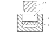
また別の金属ライナーの製造方法として、図6に示すように、ダイス11の凹部10内に金属素材12を入れ、上方から図7に示すようにパンチ13を押し込んで金属素材12をカップ14の形状に押出し成形(後方押出し成形)する方法が用いられる。
いずれの場合も、金属ライナー用のカップは、次工程で開口部が狭くなるように加工されて口部が成形され、所望の形状の圧力容器が製造される。
As another metal liner manufacturing method, as shown in FIG. 6, the
In any case, the metal liner cup is processed so that the opening is narrowed in the next step, and the mouth is formed, whereby a pressure vessel having a desired shape is manufactured.
上述したように、圧力容器用の金属ライナー用のカップは、絞り加工あるいは後方押出し成形によって成形していた。しかし、前者の絞り加工(プレス加工)による方法では、絞り加工前に予め素材を円板状に切り出す加工が必要になり、工程が増え、手間がかかるとともに加工コストが増す。また、大きな板材から複数の円板に切り出す際に隣接する円板の間に端材が生じ、材料の歩留まりを向上させることが困難であった。 As described above, a metal liner cup for a pressure vessel is formed by drawing or backward extrusion. However, in the former method by drawing (pressing), it is necessary to cut the material into a disk shape in advance before drawing, which increases the number of steps and labor, and increases the processing cost. Further, when cutting a large plate into a plurality of discs, end materials are generated between adjacent discs, and it is difficult to improve the yield of the material.
また、形成された金属ライナー用カップは、絞り加工による不均一なメタルフロー(鍛流線ともいう)の影響を受けるため、カップから形成されるライナー円筒部の強度は場所によって異なり、耐久性能がばらついていた。詳しくいえば、図8(a)に示すように、円板状に切り出された板材Aのメタルフローは圧延加工により矢印に示すように一定の方向に流れているが、パンチによる絞り加工がなされると、図8(b)に示すようにパンチで板材Aが中心対称に押圧されることになり、図中の位置(P1)と位置(P2)と位置(P3)とでメタルフローの方向が異なることになり、このためライナー円筒部の強度は場所によって異なって耐久性能がばらつくといった問題点があった。 In addition, the formed metal liner cup is affected by uneven metal flow (also called forging line) due to drawing, so the strength of the liner cylinder formed from the cup varies depending on the location, and the durability performance is It was scattered. Specifically, as shown in FIG. 8 (a), the metal flow of the plate A cut out in a disc shape flows in a certain direction as indicated by an arrow by rolling, but is drawn by a punch. Then, as shown in FIG. 8B, the plate A is pressed symmetrically with the punch as shown in FIG. 8B, and the direction of the metal flow at the positions (P1), (P2), and (P3) in the figure. Therefore, there is a problem that the durability of the liner cylindrical portion varies depending on the location and the durability performance varies.
一方、図6並びに図7の後方押出し成形では、金属素材12をパンチ13でカップ状に押し出すためには大径の容器を一挙に成形するため大きなパンチ荷重が必要になる。そのため、パワーが大きい大型の成形装置が必要になる。さらに、後方押出し成形で成形されたライナーも、底部でのメタルフローが入り乱れてランダムに発生し、胴部(側壁部)のメタルフローが延伸方向(胴部の軸芯方向)に沿って発生するので、強度並びに耐久性能が製品の場所によってばらつくといった問題点があった。
On the other hand, in the backward extrusion molding of FIGS. 6 and 7, in order to extrude the
そこで本発明は、底部のメタルフローが底部中心から放射方向に向かって形成され、側面のメタルフローが前記底部のメタルフローから連続してカップの軸線に沿って形成されているようにし、これにより、メタルフローが均一で、強度や耐久性能にばらつきのない金属ライナー用カップを提供することを目的とする。
また、本発明は、成形装置の円柱空間に円柱形の金属素材を入れた状態で、金属素材をパンチでキャビティ内に押し込むことにより、側方押出し成形でカップの底部を形成し、さらに押出し成形を続けることで側面を形成するようにし、これにより、メタルフローが均一な金属ライナー用カップの製造方法を提供することを目的とする。
Therefore, the present invention is such that the bottom metal flow is formed in the radial direction from the center of the bottom, and the side metal flow is formed continuously from the bottom metal flow along the axis of the cup. An object of the present invention is to provide a metal liner cup having a uniform metal flow and no variation in strength and durability.
In addition, the present invention forms the bottom of the cup by side extrusion molding by pushing the metal material into the cavity with a punch while the cylindrical metal material is placed in the cylindrical space of the molding apparatus, and further extrusion molding The purpose is to provide a method for producing a cup for a metal liner with a uniform metal flow.
さらに、本発明は、強度や耐久性能にばらつきのない金属ライナー用カップを、構造が簡単でコンパクトな装置により、低荷重、低コストで効率的に製作することのできる新しい製造方法を提供することを目的とする。 Furthermore, the present invention provides a new manufacturing method capable of efficiently producing a metal liner cup having no variation in strength and durability performance with a simple structure and a compact device at low load and low cost. With the goal.
本発明は、カップ形状をこれまでになかった新しい方法で製造することにより、メタルフローの方向が制御された金属ライナー用カップを形成することができるようになったものである。 The present invention makes it possible to form a cup for a metal liner in which the direction of metal flow is controlled by manufacturing a cup shape by a new method that has not been obtained so far.
すなわち、本発明の金属ライナー用カップは、底部および側面からなるカップ形状で、底部と側面との境界部分は軸線方向に滑らかに湾曲するように形成された軸対称の金属ライナー用カップであって、底部のメタルフローが底部中心から放射方向に向かって形成され、側面のメタルフローが前記底部のメタルフローから連続してカップの軸線に沿って均等に形成されているようにしたものである。 That is, the metal liner cup of the present invention is an axisymmetric metal liner cup formed in a cup shape composed of a bottom portion and a side surface, and a boundary portion between the bottom portion and the side surface is smoothly curved in the axial direction. The bottom metal flow is formed in the radial direction from the bottom center, and the side metal flow is continuously formed along the axis of the cup continuously from the bottom metal flow.
そして、本発明の金属ライナー用カップは、底部および側面からなり、底部と側面との境界部分は湾曲するように形成されたカップ形状で軸対称のキャビティが形成されるとともに、キャビティの底部中心に連通し、キャビティの軸線方向に沿って素材充填用の円柱空間が形成された金型と、円柱空間に充填された金属素材を押圧するパンチとからなる成形装置を用いる。そして、この成形装置の円柱空間に円柱形の金属素材を入れた状態で、金属素材をパンチでキャビティ内に押し込むことにより、側方押出し成形でカップの底部を形成し、さらに押出し成形を続けることで側面を形成するようにして金属ライナー用のカップを製造する。 Then, the metal liner cup of the present invention, bottom and Ri Do from the side, with the boundary portion between the bottom and sides of the axisymmetric cavity is formed in a cup shape formed to be curved, bottom center of the cavity And a molding apparatus comprising a mold in which a cylindrical space for material filling is formed along the axial direction of the cavity, and a punch for pressing the metal material filled in the cylindrical space. Then, with the cylindrical metal material placed in the cylindrical space of this molding device, the bottom of the cup is formed by side extrusion molding by pushing the metal material into the cavity with a punch, and further extrusion molding is continued. A cup for a metal liner is manufactured so as to form side surfaces.
本製造方法によれば、円柱空間に充填された金属素材は、側方押出しにより底部中心から放射状に成形されていき、さらにカップの軸線方向に沿って側面が成形されていく。このように軸対称にカップが形成されていくのでメタルフローも底部は放射状になり、側面は軸線に沿って形成されるので均質なメタルフローの金属ライナー用カップが形成される。
また、円柱空間の径を、キャビティの内径より小さくできるのでパンチの荷重を小さくすることができ、コンパクトな成形装置を実現できる。
さらにその際、一般の押出し加工のように断面減少率を大きくとるときに発生する大荷重は本法では発生せず、上下の加圧面積が一定で、一定据え込み圧縮時の荷重に加えて、側方に材料が流動する際の方向変換と接触摩擦力のみとなり、荷重は一般の押出し加工法より低くなる。
また、円柱状の金属素材を使用するので、円柱形の棒材を適当な長さに切り出せばよく成形加工前に行う素材の前処理が容易である。また、端材として廃棄される部分もほとんど発生しない。
According to this manufacturing method, the metal material filled in the cylindrical space is formed radially from the center of the bottom by side extrusion, and further, the side surface is formed along the axial direction of the cup. Since the cups are formed symmetrically in this way, the metal flow also has a radial bottom, and the side surfaces are formed along the axis, so that a uniform metal flow cup for a metal liner is formed.
Further, since the diameter of the cylindrical space can be made smaller than the inner diameter of the cavity, the punch load can be reduced, and a compact molding apparatus can be realized.
Furthermore, at this time, the large load generated when the cross-section reduction rate is increased as in general extrusion processing does not occur in this method, the upper and lower pressure areas are constant, in addition to the load during constant upsetting compression Only the direction change and the contact friction force when the material flows to the side are provided, and the load is lower than that of a general extrusion method.
In addition, since a cylindrical metal material is used, it is easy to pre-process the material before the forming process by cutting out a cylindrical bar material to an appropriate length. Moreover, the part discarded as a scrap is hardly generated.
上記発明において、金属ライナー用カップは、底部中心の外側に円柱形の凸部が一体に形成されるようにしてもよい。円柱形の金属素材の後端部分を残すことにより、次工程以降の加工の際に、この部分を支持部とすることができ、次工程(例えば口部を形成するスピニング加工)での支持が容易になる。 In the above invention, the metal liner cup may be formed integrally with a cylindrical convex portion outside the center of the bottom portion. By leaving the rear end portion of the cylindrical metal material, this portion can be used as a support portion during the subsequent processing, and support in the next step (for example, spinning processing for forming a mouth portion) can be achieved. It becomes easy.
また、金属ライナー用カップの底部と側面との境界部分(いわゆる肩部分)は軸線方向に沿って湾曲するように形成している。
このようにすれば、滑らかに連続するメタルフローが形成されるので、強度や耐久性能にばらつきのない均質な容器を安定して作成できる。
Further, the boundary portion (a so-called shoulder portion) of the bottom and the sides of the cup for the metal liner is formed so as to curve along the axial direction.
In this way, since a smoothly continuous metal flow is formed, a homogeneous container having no variation in strength and durability can be stably produced.
また、金属ライナー用カップがアルミ、アルミ合金、のいずれかであるのが好ましい。
金属素材としてのアルミ、アルミ合金等の金属は、側方押出し成形が容易に行えるので、加工コストを低減することができる。
Moreover, it is preferable that the cup for metal liners is either aluminum or an aluminum alloy.
A metal such as aluminum or aluminum alloy as a metal material can be easily subjected to side extrusion molding, so that the processing cost can be reduced.
また、上記金属ライナー用カップの製造方法において、金型は、キャビティの内面を形成するマンドレル、素材充填用の円柱空間が形成され、かつ、キャビティの外面のうち底部および底部に続く側面を形成する上部ダイス、キャビティの外面のうち上部ダイスに続く側面を形成する下部ダイスを備えるようにしてもよい。 In the metal liner cup manufacturing method, the mold includes a mandrel that forms the inner surface of the cavity, a cylindrical space for filling the material, and a bottom portion and a side surface that continues to the bottom portion of the outer surface of the cavity. You may make it provide the lower die | dye which forms the side surface following an upper die among an upper die and the outer surface of a cavity.
金型をマンドレル、上部ダイス、下部ダイスの3つに分割することにより、成形された金属ライナーをキャビティから取り出す際に、簡単に取り出すことができる。 By dividing the mold into three parts, a mandrel, an upper die, and a lower die, the molded metal liner can be easily taken out from the cavity.
また、上記製造方法において、マンドレルおよび前記上部ダイスにより形成されるキャビティの底部と側面との境界部分は、軸線方向の断面が曲線になるように形成されるようにしている。 In the above manufacturing method, the boundary portion between the bottom and sides of the cavity formed by the mandrel and the upper die, so that the axial direction of the cross section is formed so as to curve.
これにより、押し出された金属素材は底部キャビティから側面部のキャビティに滑らかに流れやすくなり、連続するメタルフローが形成されるので、強度や耐久性能にばらつきのない均質な容器を安定して作成できる。 This makes it easy for the extruded metal material to flow smoothly from the bottom cavity to the side cavity, and a continuous metal flow is formed, making it possible to stably create a homogeneous container with no variation in strength or durability. .
また、上記製造方法において、金属素材は円柱状のアルミ、アルミ合金であるのが好ましい。これらの金属は側方押出し成形が容易に行えるので、加工コストを低減することができる。 In the above manufacturing method, the metal material is preferably cylindrical aluminum or an aluminum alloy. Since these metals can be easily subjected to side extrusion, the processing cost can be reduced.
以下において本発明にかかる金属ライナー用カップ並びにその製造方法の詳細を実施の形態を示す図面に基づいて詳細に説明する。 The details of the metal liner cup and the manufacturing method thereof according to the present invention will be described below in detail with reference to the drawings showing embodiments.
図1は本発明の金属ライナー用カップを製造する際に使用される成形装置の一実施例を示す断面図である。成形装置Aは、上部ダイス1、下部ダイス2と、マンドレル3とが分解可能に組み合わされ、これらの接合面の間に金属ライナー用還付を成形するためのキャビティ4が形成されている。このキャビティ4は軸線(軸芯)Xを中心にして軸対称であり、カップ形状の底部となる皿状空間部4aと側面(いわゆる胴部)となる円筒状空間部4bとからなり、皿状空間部4aを上にした状態で形成されている。
FIG. 1 is a cross-sectional view showing an embodiment of a molding apparatus used when manufacturing a metal liner cup of the present invention. In the forming apparatus A, an
キャビティ4の上方には、皿状空間部4aに連通し、キャビティ4の軸線(軸芯)Xに沿って、上部ダイス1を貫通する円柱空間5が設けられている。円柱空間5は金属素材6を導入するための孔である。円柱空間5の直径は、キャビティ4の筒状空間部4bの内径よりも小径にしてある。この径が小さいほど、後述するパンチ7による押圧荷重を小さくできるが、筒状空間部4bの内径Dに対し、0.2D〜0.8Dにするのが好ましい。なお、円柱空間5の直径を、加工に使用する円柱状の金属素材6の外径に合わせておくことにより、円柱空間5に挿入する前に行う金属素材6に対する加工を簡略化できる。
Above the
なお、金型(上部ダイス1、下部ダイス2、マンドレル3)の組み立てを容易にするためのガイドとして、ベースプレート21、支柱22、リングガイド23、上部プレート24を設けるようにしてある。
As a guide for facilitating assembly of the mold (
そして円柱空間5には、金属素材6を押圧するためのパンチ7が挿入される。金属素材6の材質は、アルミ、アルミ合金が特に好ましいが、成形可能な素材であればその材質は限定されない。
A
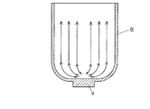
次に、上記の成形装置Aによる加工動作について説明する。円柱空間5内に、円柱空間5と同径の円柱状の金属素材6を、キャビティ4の軸線Xと金属素材6の軸線とを一致させた状態で挿入する。そして、この金属素材6をパンチ7で押圧し、キャビティ4内に押し込むことにより、図2に示す金属ライナー用カップBを側方押出し成形で製造していく。パンチ7で金属素材5がキャビティ4に押し込まれる初期の段階で、金属素材5は延伸されてキャビティ4の皿状空間部4aの中心部から該空間部4aの湾曲した肩部に向かって放射方向に流動する。この際、円柱状の金属素材6の軸線とキャビティ4の軸線Xとを一致させてあるので、延伸された金属は皿状空間部4aの中心から放射方向に向かって円を描くように均等に流動する。
Next, the processing operation by the molding apparatus A will be described. A
次いで、延伸された金属は、皿状空間部4aの湾曲した肩部から筒状空間部4bに流入し、筒状空間部4aに沿って下方に流動する。その結果、金属ライナー用カップBのメタルフローは、図2の矢印で示すように、底部では底部中心から放射方向に向かって形成され、側面(胴部)では底部のメタルフローから連続して軸線X方向に沿って均等に形成されることになる。これにより、円筒状胴部のどの部位をとっても均一な強度となって製品のばらつきのない高品質の金属ライナー用カップを得ることができる。 Next, the stretched metal flows into the cylindrical space portion 4b from the curved shoulder portion of the dish-shaped space portion 4a, and flows downward along the cylindrical space portion 4a. As a result, the metal flow of the metal liner cup B is formed in the radial direction from the center of the bottom at the bottom, as indicated by the arrow in FIG. It is formed uniformly along the X direction. As a result, it is possible to obtain a high-quality metal liner cup having uniform strength regardless of the portion of the cylindrical body portion and having no product variation.
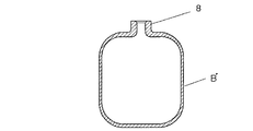
このようにして製造された金属ライナー用カップBは、次工程で、周知のスピニング加工等により開口部を絞り込むことによって、図3に示すように口部8を狭くした容器状の金属ライナーB’に成形される。 The metal liner cup B manufactured in this way is a container-shaped metal liner B ′ having a narrowed opening 8 as shown in FIG. 3 by narrowing the opening by a known spinning process or the like in the next step. To be molded.
なお、次工程での加工を容易にするため、図4に示すように、金属ライナーBの底部外側に凸部9を形成しておいてもよい。これは、パンチ7で円柱空間5内の金属素材6を押し出す際に、金属素材6の一部を残しておくことにより簡単に形成できる。このようにすることで、次工程で口部8を加工する際に、チャックで凸部9を支持することができるようになり、スピニング加工後に切り落とせば、最終的に図2の形状にすることもできる。さらに凸部9の別の利用方法として、図5に示すように、凸部9にネジ穴9aを形成するようにして、金属ライナー用カップBを固定することもできる。
In order to facilitate the processing in the next step, a
以上、本発明の代表的な実施例について説明したが、本発明は必ずしも上記の実施形態に特定されるものではない。例えば、成形装置Aのキャビティ4の形状を、メタルフローに影響を与えない範囲で修正を加えることにより底部の肉厚と胴部の肉厚を代えたり、あるいは次工程で口部を絞り加工するための肉厚部分を胴部の開口部付近に形成するようにしてもよい。
As mentioned above, although the typical Example of this invention was described, this invention is not necessarily specified to said embodiment. For example, the shape of the
また、上記実施形態では、上部ダイス1を上に配置しマンドレル3を下に配置しているが、上下逆に配置した金型としてもよい。
さらに、上部ダイス1の底部の材料流入初期部分にマンドレル3と形成されるギャップは一定ではなく、初期に大きく段階的に小さくし、最終的に所定の肉厚にすることによって、成形性の向上、成形荷重の低減が可能となる。また上部ダイス1を分割にし、復動プレスをすることによって、ギャップに流入する肉厚を制御することもできる。
その他本発明では、その目的を達成し、請求の範囲を逸脱しない範囲内で適宜修正、変更することが可能である。
In the above embodiment, the
Furthermore, the gap formed with the
Others The present invention can be appropriately modified and changed within the scope of achieving the object and without departing from the scope of the claims.
本発明の金属ライナー用カップは、水素その他の各種加圧物質を充填するための圧力容器に用いられ、特に、燃料電池自動車の水素用燃料タンク等に適用される。 The metal liner cup of the present invention is used in a pressure vessel for filling hydrogen and other various pressurized substances, and is particularly applied to a hydrogen fuel tank of a fuel cell vehicle.
A 成形装置
B 金属ライナー用カップ
4 キャビティ
4a キャビティの皿状空間部
4b キャビティの筒状空間部
5 素材充填用空間
6 金属素材
7 パンチ
8 口部
9 凸部
A Molding device B
Claims (6)
Priority Applications (1)
| Application Number | Priority Date | Filing Date | Title |
|---|---|---|---|
| JP2010053496A JP5740095B2 (en) | 2010-03-10 | 2010-03-10 | Metal liner cup and method for producing the same |
Applications Claiming Priority (1)
| Application Number | Priority Date | Filing Date | Title |
|---|---|---|---|
| JP2010053496A JP5740095B2 (en) | 2010-03-10 | 2010-03-10 | Metal liner cup and method for producing the same |
Publications (3)
| Publication Number | Publication Date |
|---|---|
| JP2011183444A JP2011183444A (en) | 2011-09-22 |
| JP2011183444A5 JP2011183444A5 (en) | 2013-03-14 |
| JP5740095B2 true JP5740095B2 (en) | 2015-06-24 |
Family
ID=44790349
Family Applications (1)
| Application Number | Title | Priority Date | Filing Date |
|---|---|---|---|
| JP2010053496A Active JP5740095B2 (en) | 2010-03-10 | 2010-03-10 | Metal liner cup and method for producing the same |
Country Status (1)
| Country | Link |
|---|---|
| JP (1) | JP5740095B2 (en) |
Families Citing this family (1)
| Publication number | Priority date | Publication date | Assignee | Title |
|---|---|---|---|---|
| JP6711066B2 (en) | 2016-03-28 | 2020-06-17 | セイコーエプソン株式会社 | Robot, gear device, and method for manufacturing flexible gear |
Family Cites Families (4)
| Publication number | Priority date | Publication date | Assignee | Title |
|---|---|---|---|---|
| JPH04300043A (en) * | 1991-03-28 | 1992-10-23 | Hiromi Kataoka | Forging forming vessel and method and device for forming its vessel |
| JP3364073B2 (en) * | 1995-12-27 | 2003-01-08 | ワイケイケイ株式会社 | Manufacturing method of press-formed product |
| JPH10180348A (en) * | 1996-12-20 | 1998-07-07 | Toyota Central Res & Dev Lab Inc | Manufacture of hollow extruded stock |
| JP3750449B2 (en) * | 1998-12-07 | 2006-03-01 | トヨタ自動車株式会社 | Method for producing aluminum liner for high pressure gas container and method for producing high pressure gas container |
-
2010
- 2010-03-10 JP JP2010053496A patent/JP5740095B2/en active Active
Also Published As
| Publication number | Publication date |
|---|---|
| JP2011183444A (en) | 2011-09-22 |
Similar Documents
| Publication | Publication Date | Title |
|---|---|---|
| JP6413187B2 (en) | Manufacturing method of pressure vessel liner | |
| CN104226777B (en) | A kind of deep camber thin-wall member resisting medium external pressure shaping method | |
| CN102248114A (en) | Process and die for forming automobile hub by integrally forging and extruding light alloy | |
| CN1962107A (en) | Internal and external pressurization compound forming method for axisymmetric thin-wall special-shaped curved work piece with large section surface | |
| MX2015003951A (en) | Press molding method. | |
| JP2017094389A (en) | Double cross section extrusion device and extrusion method | |
| JP5740095B2 (en) | Metal liner cup and method for producing the same | |
| CN107186160A (en) | The quiet step forming process of disk two of new-energy automotive air-conditioning compressor | |
| CN107671132A (en) | A kind of forming technology of speed torque-converters hub | |
| CN102284540A (en) | Cold extrusion forming mould for input shaft in electric power redirector | |
| US6688153B2 (en) | Toothed part with a shaft and molding method for the same | |
| TW202122173A (en) | Extrusion device and extrusion method thereof | |
| JP5581456B2 (en) | Engine valve forging system | |
| CN105499418A (en) | Necking device of ultrathin-wall cylindrical part and application method of necking device | |
| JP6162540B2 (en) | Manufacturing method of wheel disc for vehicle | |
| JP2012045618A (en) | Method of manufacturing diffuser | |
| RU2451569C2 (en) | Method of mass extruding of barrel-type parts by angular extrusion at horizontal hydraulic extruder | |
| JP5680706B2 (en) | Multi-action extrusion molding apparatus, multi-action extrusion molding machine and extrusion molding method | |
| JP2005009673A (en) | Method of manufacture of pressure vessel | |
| JP4429117B2 (en) | Method of manufacturing aluminum alloy automobile wheel rim | |
| JPH1157906A (en) | Manufacture of seamless can | |
| JP2011225132A (en) | Method of manufacturing vehicle wheel | |
| JP2004322104A (en) | Drawing die and drawing method | |
| US20160354819A1 (en) | Extrusion press for producing flat sheets | |
| Wang et al. | Stamping-forging processing of sheet metal parts |
Legal Events
| Date | Code | Title | Description |
|---|---|---|---|
| A521 | Request for written amendment filed |
Free format text: JAPANESE INTERMEDIATE CODE: A523 Effective date: 20130128 |
|
| A621 | Written request for application examination |
Free format text: JAPANESE INTERMEDIATE CODE: A621 Effective date: 20130128 |
|
| A131 | Notification of reasons for refusal |
Free format text: JAPANESE INTERMEDIATE CODE: A131 Effective date: 20140204 |
|
| A521 | Request for written amendment filed |
Free format text: JAPANESE INTERMEDIATE CODE: A523 Effective date: 20140403 |
|
| A131 | Notification of reasons for refusal |
Free format text: JAPANESE INTERMEDIATE CODE: A131 Effective date: 20140819 |
|
| A521 | Request for written amendment filed |
Free format text: JAPANESE INTERMEDIATE CODE: A523 Effective date: 20141007 |
|
| TRDD | Decision of grant or rejection written | ||
| A01 | Written decision to grant a patent or to grant a registration (utility model) |
Free format text: JAPANESE INTERMEDIATE CODE: A01 Effective date: 20150414 |
|
| A61 | First payment of annual fees (during grant procedure) |
Free format text: JAPANESE INTERMEDIATE CODE: A61 Effective date: 20150427 |
|
| R150 | Certificate of patent or registration of utility model |
Ref document number: 5740095 Country of ref document: JP Free format text: JAPANESE INTERMEDIATE CODE: R150 |
|
| R250 | Receipt of annual fees |
Free format text: JAPANESE INTERMEDIATE CODE: R250 |
|
| R250 | Receipt of annual fees |
Free format text: JAPANESE INTERMEDIATE CODE: R250 |
|
| R250 | Receipt of annual fees |
Free format text: JAPANESE INTERMEDIATE CODE: R250 |
|
| R250 | Receipt of annual fees |
Free format text: JAPANESE INTERMEDIATE CODE: R250 |
|
| R250 | Receipt of annual fees |
Free format text: JAPANESE INTERMEDIATE CODE: R250 |
|
| R250 | Receipt of annual fees |
Free format text: JAPANESE INTERMEDIATE CODE: R250 |