JP5728552B2 - Non-woven fabric bulk recovery device and non-woven fabric bulk recovery method - Google Patents
Non-woven fabric bulk recovery device and non-woven fabric bulk recovery method Download PDFInfo
- Publication number
- JP5728552B2 JP5728552B2 JP2013217194A JP2013217194A JP5728552B2 JP 5728552 B2 JP5728552 B2 JP 5728552B2 JP 2013217194 A JP2013217194 A JP 2013217194A JP 2013217194 A JP2013217194 A JP 2013217194A JP 5728552 B2 JP5728552 B2 JP 5728552B2
- Authority
- JP
- Japan
- Prior art keywords
- nonwoven fabric
- hot air
- case member
- space
- transport direction
- Prior art date
- Legal status (The legal status is an assumption and is not a legal conclusion. Google has not performed a legal analysis and makes no representation as to the accuracy of the status listed.)
- Active
Links
Images


Classifications
-
- D—TEXTILES; PAPER
- D06—TREATMENT OF TEXTILES OR THE LIKE; LAUNDERING; FLEXIBLE MATERIALS NOT OTHERWISE PROVIDED FOR
- D06C—FINISHING, DRESSING, TENTERING OR STRETCHING TEXTILE FABRICS
- D06C7/00—Heating or cooling textile fabrics
-
- D—TEXTILES; PAPER
- D04—BRAIDING; LACE-MAKING; KNITTING; TRIMMINGS; NON-WOVEN FABRICS
- D04H—MAKING TEXTILE FABRICS, e.g. FROM FIBRES OR FILAMENTARY MATERIAL; FABRICS MADE BY SUCH PROCESSES OR APPARATUS, e.g. FELTS, NON-WOVEN FABRICS; COTTON-WOOL; WADDING ; NON-WOVEN FABRICS FROM STAPLE FIBRES, FILAMENTS OR YARNS, BONDED WITH AT LEAST ONE WEB-LIKE MATERIAL DURING THEIR CONSOLIDATION
- D04H1/00—Non-woven fabrics formed wholly or mainly of staple fibres or like relatively short fibres
- D04H1/70—Non-woven fabrics formed wholly or mainly of staple fibres or like relatively short fibres characterised by the method of forming fleeces or layers, e.g. reorientation of fibres
-
- D—TEXTILES; PAPER
- D06—TREATMENT OF TEXTILES OR THE LIKE; LAUNDERING; FLEXIBLE MATERIALS NOT OTHERWISE PROVIDED FOR
- D06C—FINISHING, DRESSING, TENTERING OR STRETCHING TEXTILE FABRICS
- D06C17/00—Fulling
-
- D—TEXTILES; PAPER
- D06—TREATMENT OF TEXTILES OR THE LIKE; LAUNDERING; FLEXIBLE MATERIALS NOT OTHERWISE PROVIDED FOR
- D06C—FINISHING, DRESSING, TENTERING OR STRETCHING TEXTILE FABRICS
- D06C3/00—Stretching, tentering or spreading textile fabrics; Producing elasticity in textile fabrics
Landscapes
- Engineering & Computer Science (AREA)
- Textile Engineering (AREA)
- Mechanical Engineering (AREA)
- Treatment Of Fiber Materials (AREA)
- Nonwoven Fabrics (AREA)
- Absorbent Articles And Supports Therefor (AREA)
Description
本発明は、不織布の嵩回復装置、及び不織布の嵩回復方法に関する。 The present invention relates to a nonwoven fabric bulk recovery device and a nonwoven fabric bulk recovery method.
従来、吸収性物品として生理用ナプキンや使い捨ておむつが使用されている。また、同吸収性物品の範疇に含まれるペットシートも、ペット用トイレとして普及している。かような吸収性物品において使用者等の肌が当たる部分には、液透過性のトップシートが設けられている。そして、近年、トップシートには、肌へのべたつき低減などの観点から、高い液捌け性が求められ、その材料としては嵩高な不織布が好適とされている。 Conventionally, sanitary napkins and disposable diapers have been used as absorbent articles. In addition, pet sheets included in the category of the absorbent article are also widely used as pet toilets. In such an absorbent article, a liquid-permeable top sheet is provided in a portion where the skin of a user or the like hits. In recent years, the top sheet is required to have high liquid repellency from the viewpoint of reducing stickiness to the skin, and a bulky nonwoven fabric is suitable as the material.
かかる不織布は、カード法等の適宜な方法で帯状に製造され、しかる後に、ロール状に巻き取られて、不織布原反の形態で保管される。そして、使用すべき時がきたら、不織布原反は吸収性物品の製造ラインに搬入されて、同ラインにて同原反から不織布が繰り出されて、トップシートの材料として使用される。 Such a nonwoven fabric is manufactured in a strip shape by an appropriate method such as a card method, and then wound up into a roll shape and stored in the form of a nonwoven fabric. And when it is time to use, the nonwoven fabric raw material is carried into the manufacturing line of an absorbent article, and a nonwoven fabric is drawn | fed out from the raw material material in the same line, and is used as a material of a top sheet.
一方、不織布を不織布原反に巻き取る際には、当該不織布の蛇行等を防ぐべく、巻き取り方向に張力を付与しながら巻き取る。そのため、通常は、当該張力に起因して不織布は巻き締まっている。すなわち、当該不織布は厚さ方向に圧縮されて、嵩が減った状態になっている。よって、吸収性物品の製造ラインにて不織布原反から不織布を繰り出しても、嵩が減少した不織布が繰り出されて供給されるだけであり、つまり、上述の嵩高な不織布の要求に応えることができない。 On the other hand, when the non-woven fabric is wound on the non-woven fabric, the non-woven fabric is wound while applying tension in the winding direction in order to prevent meandering of the non-woven fabric. Therefore, the nonwoven fabric is usually wound up due to the tension. That is, the nonwoven fabric is compressed in the thickness direction, and the bulk is reduced. Therefore, even if the nonwoven fabric is fed out from the nonwoven fabric raw material in the absorbent article production line, the nonwoven fabric with reduced volume is only fed out and supplied, that is, it cannot meet the above-mentioned demand for the bulky nonwoven fabric. .
不織布を嵩高にする方法として、不織布の表面に熱風を吹き付ける等の処理を行ない、不織布の表面を加熱することによって圧縮された不織布の繊維を元の状態に戻し、嵩を回復する方法が知られている。例えば特許文献1には、不織布を加熱するための加熱室を用意し、不織布が当該加熱室の入口側から出口側へと搬送される際に、加熱室の入口側若しくは出口の一方の側から熱風を吹き入れる方法が開示されている。加熱室に吹き入れられた熱風は、入口若しくは出口の他方の側から排出されることにより、加熱室内において不織布の表面に沿って流れ、不織布の嵩を回復させることができる。
As a method for making the nonwoven fabric bulky, a method is known in which the processing is performed such as blowing hot air on the surface of the nonwoven fabric, the compressed nonwoven fabric fiber is returned to its original state by heating the nonwoven fabric surface, and the bulk is restored. ing. For example, in
嵩回復装置では不織布を加熱するので、不織布は軟化する。すると、搬送方向の張力が作用した際に不織布は搬送方向に伸びやすくなる。そして、特許文献1のように不織布の表面に沿って熱風が流れる場合、熱風の流れ(流速)が速いと当該熱風の流れに牽引されることによって不織布が搬送方向により伸びやすくなる。特に、加熱室の搬送方向下流側では不織布が熱風にさらされて加熱される時間が長くなるため、当該領域において熱風の流速が速すぎる場合には不織布の伸びの影響が大きくなり、正常な嵩回復を行なうことが困難になる。
Since the nonwoven fabric is heated in the bulk recovery device, the nonwoven fabric softens. Then, when the tension | tensile_strength of a conveyance direction acts, a nonwoven fabric becomes easy to extend in a conveyance direction. And when a hot air flows along the surface of a nonwoven fabric like
本発明は、上述のような問題に鑑みてなされたものであって、その目的とするところは、搬送される不織布に熱風を吹き付けることによって嵩を回復する装置において、熱風の流速を適当に調整することにある。 The present invention has been made in view of the above-described problems, and the object of the present invention is to appropriately adjust the flow rate of hot air in an apparatus that recovers bulk by blowing hot air on a nonwoven fabric to be conveyed. There is to do.
上述目的を達成するための主たる発明は、
搬送方向に搬送される不織布に熱風を吹き付けて加熱することにより前記不織布の嵩を回復する装置であって、前記搬送方向の両端部が開口されたケース部材を有し、前記ケース部材の前記搬送方向の一端側の開口には前記不織布が搬送される際の入口が設けられ、前記ケース部材の前記搬送方向の他端側の開口には前記不織布が搬送される際の出口が設けられ、前記ケース部材の前記入口側の部分には、前記出口側の部分に向けて前記ケース部材内の空間に前記熱風を噴射する噴射口が設けられ、前記噴射口が設けられた位置よりも前記搬送方向の下流側の第1位置における前記ケース部材内の空間の断面積は、前記搬送方向において前記噴射口が設けられた位置と前記第1位置との間の第2位置における前記ケース部材内の空間の断面積よりも大きくなっており、前記噴射口から噴射された前記熱風は、前記ケース部材内の空間において前記不織布の両面のうちの一方の面に接触しながら、前記搬送方向の上流側から前記搬送方向の下流側へ、前記第1位置及び前記第2位置を通って流れる、ことを特徴とする不織布の嵩回復装置である。
本発明の他の特徴については、本明細書及び添付図面の記載により明らかにする。
The main invention for achieving the above-mentioned object is:
An apparatus for recovering the bulk of the nonwoven fabric by blowing hot air on the nonwoven fabric transported in the transport direction and heating the nonwoven fabric, comprising a case member having both ends in the transport direction opened, and transporting the case member The opening at the one end side in the direction is provided with an inlet when the nonwoven fabric is conveyed, and the opening at the other end side in the conveying direction of the case member is provided with an outlet when the nonwoven fabric is conveyed, The inlet side portion of the case member is provided with an injection port for injecting the hot air into the space in the case member toward the outlet side portion, and the transport direction is more than the position where the injection port is provided. The cross-sectional area of the space in the case member at the first position on the downstream side is the space in the case member at the second position between the position where the injection port is provided and the first position in the transport direction. Cross section of The hot air jetted from the jet port is in contact with one surface of both surfaces of the nonwoven fabric in the space in the case member, and from the upstream side in the transport direction to the transport direction. The nonwoven fabric bulk recovery apparatus is characterized in that it flows through the first position and the second position to the downstream side of the nonwoven fabric.
Other features of the present invention will become apparent from the description of the present specification and the accompanying drawings.
本発明によれば、搬送される不織布に熱風を吹き付けることによって嵩を回復する装置において、熱風の流速を適当に調整することができる。 ADVANTAGE OF THE INVENTION According to this invention, the flow velocity of a hot air can be appropriately adjusted in the apparatus which recovers a bulk by spraying a hot air on the nonwoven fabric conveyed.
本明細書及び添付図面の記載により、少なくとも以下の事項が明らかとなる。
搬送方向に搬送される不織布に熱風を吹き付けて加熱することにより前記不織布の嵩を回復する装置であって、前記搬送方向の両端部が開口されたケース部材を有し、前記ケース部材の前記搬送方向の一端側の開口には前記不織布が搬送される際の入口が設けられ、前記ケース部材の前記搬送方向の他端側の開口には前記不織布が搬送される際の出口が設けられ、前記ケース部材の前記入口側の部分には、前記出口側の部分に向けて前記ケース部材内の空間に前記熱風を噴射する噴射口が設けられ、前記噴射口が設けられた位置よりも前記搬送方向の下流側の第1位置における前記ケース部材内の空間の断面積は、前記搬送方向において前記噴射口が設けられた位置と前記第1位置との間の第2位置における前記ケース部材内の空間の断面積よりも大きくなっており、前記噴射口から噴射された前記熱風は、前記ケース部材内の空間において前記不織布の両面のうちの一方の面に接触しながら、前記搬送方向の上流側から前記搬送方向の下流側へ、前記第1位置及び前記第2位置を通って流れる、ことを特徴とする不織布の嵩回復装置。
At least the following matters will become apparent from the description of the present specification and the accompanying drawings.
An apparatus for recovering the bulk of the nonwoven fabric by blowing hot air on the nonwoven fabric transported in the transport direction and heating the nonwoven fabric, comprising a case member having both ends in the transport direction opened, and transporting the case member The opening at the one end side in the direction is provided with an inlet when the nonwoven fabric is conveyed, and the opening at the other end side in the conveying direction of the case member is provided with an outlet when the nonwoven fabric is conveyed, The inlet side portion of the case member is provided with an injection port for injecting the hot air into the space in the case member toward the outlet side portion, and the transport direction is more than the position where the injection port is provided. The cross-sectional area of the space in the case member at the first position on the downstream side is the space in the case member at the second position between the position where the injection port is provided and the first position in the transport direction. Cross section of The hot air jetted from the jet port is in contact with one surface of both surfaces of the nonwoven fabric in the space in the case member, and from the upstream side in the transport direction to the transport direction. The nonwoven fabric bulk recovery device, which flows through the first position and the second position to the downstream side of the nonwoven fabric.
このような不織布の嵩回復装置によれば、搬送方向下流側の領域において熱風の流路面積(断面積)を拡張することで熱風の流速を小さくすることができる。これにより、熱風の流速が適当に調整され、不織布が搬送方向に伸びることを抑制して正常な嵩回復を行なうことができる。 According to such a nonwoven fabric bulk recovery device, the flow velocity of hot air can be reduced by expanding the flow passage area (cross-sectional area) of the hot air in the downstream region in the transport direction. Thereby, the flow velocity of the hot air is appropriately adjusted, and it is possible to perform normal bulk recovery by suppressing the nonwoven fabric from extending in the transport direction.
かかる不織布の嵩回復装置であって、前記ケース部材内の空間で、前記第1位置を含み、前記第2位置よりも断面積が大きくなっている領域には、前記ケース部材内の空間に噴射された前記熱風を外に排出する排出口が設けられている、ことが望ましい。 In this non-woven fabric bulk recovery device, in the space in the case member, the region including the first position and having a larger cross-sectional area than the second position is injected into the space in the case member. It is desirable that a discharge port for discharging the heated hot air to the outside is provided.
このような不織布の嵩回復装置によれば、ケース部材内に噴射された熱風の一部を排出口から排出することで搬送方向の下流側の領域において熱風の体積を減らすことができる。これにより、搬送方向下流側の領域で熱風の流速をより小さくすることが可能となる。 According to such a bulk recovery device for nonwoven fabric, the volume of hot air can be reduced in the downstream region in the transport direction by discharging a portion of the hot air injected into the case member from the discharge port. Thereby, the flow velocity of the hot air can be further reduced in the region on the downstream side in the transport direction.
かかる不織布の嵩回復装置であって前記排出口は、鉛直方向において前記不織布が搬送される経路からずれた位置に設けられている、ことが望ましい。 In this nonwoven fabric bulk recovery device, it is preferable that the discharge port is provided at a position shifted in a vertical direction from a path along which the nonwoven fabric is conveyed.
このような不織布の嵩回復装置によれば、熱風が排出口から排出される際の流れの影響により不織布の搬送動作が妨げられる等の問題は生じにくく、不織布の正確な搬送動作を行うことができる。 According to such a nonwoven fabric bulk recovery device, problems such as the nonwoven fabric transport operation being hindered by the influence of the flow when hot air is discharged from the outlet are less likely to occur, and the nonwoven fabric can be accurately transported. it can.
かかる不織布の嵩回復装置であって前記噴射口及び前記排出口は、共に前記不織布が搬送される経路に対して鉛直方向の同じ側にずれた位置に設けられている、ことが望ましい。 In this nonwoven fabric bulk recovery device, it is desirable that both the ejection port and the discharge port are provided at positions shifted to the same side in the vertical direction with respect to a path through which the nonwoven fabric is conveyed.
このような不織布の嵩回復装置によれば、搬送方向上流側に設けられる噴射口から噴射された熱風は、不織布を貫通することなく搬送方向に沿って流れ、搬送方向下流側に設けられる排出口から外に排出される。これにより、不織布の一方の面(例えば不織布の下面側)を十分に加熱することができ、効率的に嵩回復を行うことができる。 According to such a nonwoven fabric bulk recovery device, the hot air sprayed from the jet port provided on the upstream side in the transport direction flows along the transport direction without penetrating the nonwoven fabric, and is provided on the downstream side in the transport direction. Is discharged from the outside. Thereby, one side (for example, the lower surface side of a nonwoven fabric) of a nonwoven fabric can fully be heated, and bulk recovery can be performed efficiently.
かかる不織布の嵩回復装置であって前記ケース部材内の空間の前記搬送方向の最下流部には、前記ケース部材内の空間の出口側の空間の一部を塞ぐ部材が設けられている、ことが望ましい。 In this nonwoven fabric bulk recovery device, a member for closing a part of the space on the outlet side of the space in the case member is provided at the most downstream part in the transport direction of the space in the case member. Is desirable.
このような不織布の嵩回復装置によれば、ケース部材の出口部分の断面積を狭くすることによって熱風の流れを絞り、熱風の流れを整流することができる。これにより、当該出口部分における不織布の搬送動作が乱されにくくなり、安定した嵩回復動作を行うことができる。 According to such a nonwoven fabric bulk recovery device, the flow of hot air can be squeezed by narrowing the cross-sectional area of the outlet portion of the case member, and the flow of hot air can be rectified. Thereby, the conveyance operation | movement of the nonwoven fabric in the said exit part becomes difficult to be disturb | confused, and the stable bulk recovery operation | movement can be performed.
かかる不織布の嵩回復装置であって、前記ケース部材内に前記熱風を供給する熱風供給装置を備え、前記熱風供給装置は、前記排出口から排出された前記熱風を回収して、前記ケース部材内に再度供給する、ことが望ましい。 A non-woven fabric bulk recovery device comprising a hot air supply device that supplies the hot air into the case member, wherein the hot air supply device collects the hot air discharged from the discharge port, It is desirable to supply again.
このような不織布の嵩回復装置によれば、ケース部材から熱風が排出される際に近傍の他の中間製品へ悪影響を与えることを抑制しつつ、エネルギーの一部を再利用することができる。 According to such a bulk recovery device for nonwoven fabric, part of the energy can be reused while suppressing adverse effects on other intermediate products in the vicinity when hot air is discharged from the case member.
かかる不織布の嵩回復装置であって、前記ケース部材の鉛直方向及び前記搬送方向とそれぞれ直行する方向であるCD方向を有し、前記排出口からの前記熱風の排出と、前記ケース部材内への前記熱風の供給とが、前記ケース部材の前記CD方向の同じ側から行われる、ことが望ましい。 Such a nonwoven fabric bulk recovery device has a CD direction that is perpendicular to the vertical direction and the transport direction of the case member, and discharges the hot air from the discharge port and into the case member. It is desirable that the hot air is supplied from the same side of the case member in the CD direction.
このような不織布の嵩回復装置によれば、熱風を供給するための配管と、熱風を排出・回収するための配管とをCD方向の同じ側に接続することが可能となり、配管の取り回しスペースを小さくすることができる。これにより、嵩回復装置全体を小型化することができる。 According to such a non-woven fabric bulk recovery device, it is possible to connect a pipe for supplying hot air and a pipe for discharging / collecting hot air to the same side in the CD direction. Can be small. Thereby, the whole bulk recovery apparatus can be reduced in size.
また、搬送方向に搬送される不織布に熱風を吹き付けて加熱することにより前記不織布の嵩を回復する方法であって、前記搬送方向の両端部が開口されたケース部材において、前記搬送方向の一端側の開口には前記不織布が搬送される際の入口が設けられ、前記搬送方向の他端側の開口には前記不織布が搬送される際の出口が設けられている場合に、前記ケース部材の前記入口側の部分に設けられた噴射口から、前記出口側の部分に向けて前記ケース部材内の空間に前記熱風を噴射する工程と、前記噴射口が設けられた位置よりも前記搬送方向の下流側の第1位置における前記ケース部材内の空間の断面積が、前記搬送方向において前記噴射口が設けられた位置と前記第1位置との間の第2位置における前記ケース部材内の空間の断面積よりも大きくなっている前記ケース部材において、前記噴射口から噴射された前記熱風を前記不織布の両面のうちの一方の面と接触させながら、前記搬送方向の上流側から前記搬送方向の下流側へ、前記第1位置及び前記第2位置を通って流す工程と、を有する、ことを特徴とする不織布の嵩回復方法が明らかとなる。 Moreover, it is a method of recovering the bulk of the nonwoven fabric by blowing hot air on the nonwoven fabric conveyed in the conveyance direction, and in the case member having both ends in the conveyance direction opened, one end side in the conveyance direction The opening of the case member is provided with an inlet when the nonwoven fabric is conveyed, and the opening at the other end side in the conveying direction is provided with an outlet when the nonwoven fabric is conveyed. A step of injecting the hot air into the space in the case member from the injection port provided in the inlet side portion toward the outlet side portion, and the downstream of the transport direction from the position where the injection port is provided The cross-sectional area of the space in the case member at the first position on the side is a disconnection of the space in the case member at the second position between the position where the injection port is provided and the first position in the transport direction. From area In the case member that is large, while the hot air jetted from the jet port is in contact with one surface of both surfaces of the nonwoven fabric, from the upstream side in the transport direction to the downstream side in the transport direction, And a step of flowing through the first position and the second position. The method for recovering the bulk of the nonwoven fabric is characterized.
このような不織布の嵩回復方法によれば、搬送方向下流側の領域において熱風の流路面積(断面積)が拡張されていることで、当該領域における熱風の流速を小さくすることができる。すなわち、熱風の流速が適当に調整され、不織布が搬送方向に伸びることを抑制して正常な嵩回復を行なうことができる。 According to such a nonwoven fabric bulk recovery method, the flow area of the hot air (cross-sectional area) is expanded in the region on the downstream side in the transport direction, so that the flow velocity of the hot air in the region can be reduced. That is, the flow rate of the hot air is appropriately adjusted, and the normal bulk recovery can be performed by suppressing the nonwoven fabric from extending in the transport direction.
===実施形態===
<嵩回復対象となる不織布について>
本実施形態の不織布3の嵩回復装置20及び嵩回復方法は、ペットシート1のトップシート3となる不織布3を処理対象とする。
=== Embodiment ===
<About non-woven fabrics subject to bulk recovery>
The
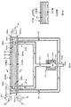
図1Aは、吸収性物品の一例としてのペットシート1の外観斜視図であり、図1Bは、図1A中のB−B線で同シート1を切断した場合の拡大斜視図である。
FIG. 1A is an external perspective view of a
ペットシート1は、犬や猫などの動物の排泄処理に使用されるものであり、図1Aに示すように、床などに敷いて使用される。かかるペットシート1は、例えば平面視矩形状の液透過性のトップシート3と、略同形状の液不透過性のバックシート5と、これらのシート3,5同士の間に介挿される液吸収性の吸収体4と、を有している。そして、吸収体4は、トップシート3及びバックシート5の両者とホットメルト接着剤等で接合されており、また、トップシート3とバックシート5とは、吸収体4から側方にはみ出す部分3e,5e、すなわち、各シート3,5の外周縁部3e,5eにてホットメルト接着剤等で接合されている。
The
図1Bに示すように、吸収体4は、例えば、パルプ繊維等の液体吸収性繊維及び高吸収性ポリマー(所謂SAP)を平面視略矩形形状に積層してなる吸収性コア4cを有する。同コア4cは、ティッシュペーパー等の二枚の液透過性の被覆シート4t1,4t2で被覆されていても良く、この例では、そうなっている。すなわち、肌側面から一枚の被覆シート4t1で覆われ、そして、非肌側面からもう一枚の被覆シート4t2で覆われている。なお、場合によっては、一枚の被覆シートで吸収性コア4cの全面を被覆しても良い。
As shown in FIG. 1B, the
バックシート5は、例えば、ポリエチレン(以下、PE)、ポリプロピレン(以下、PP)、及びポリエチレンテレフタレート(以下、PET)等のフィルム材である。但し、何等これらに限るものではなく、液不透過性のシートであれば、使用可能である。
The
トップシート3は、不織布3を材料とする。この例では、不織布3の両面3a,3bのうちの一方の面3bは略平坦面であるが、もう一方の面3aは、波形形状をなしている。すなわち、直線状の溝部3tと直線状の突部3pとが交互に形成されている。かかる突部3p,3p…は、周知の空気流の吹き付け処理(特開2009−11179号などを参照)によって、元々溝部3tの部分にあった繊維が横に吹き寄せられて盛り上がることで形成されたものであり、繊維間隙間が大きい疎な状態に形成されている。そして、これにより、当該不織布3は、全体として嵩高になっている。また、溝部3tには、厚さ方向に貫通した複数の貫通孔3h,3h…が形成されていても良く、この例では、そうなっている。
The
かかる不織布3の平均坪量は、例えば10〜200(g/m2)であり、突部3pにおける中央部の平均坪量は、例えば15〜250(g/m2)であり、溝部3tにおける底部の平均坪量は、3〜150(g/m2)である。
The average basis weight of the
また、不織布3の繊維としては、芯と鞘とが異なる部材によって構成される所謂芯鞘構造の複合繊維が好適であるが、サイドバイサイド構造の繊維でも良いし、単一の熱可塑性樹脂からなる単独繊維でも良い。
Moreover, as the fiber of the
さらに、不織布3は、捲縮繊維を有していても良い。なお、捲縮繊維とは、ジグザグ形状やΩ形状、スパイラル形状等の捲縮形状を有した繊維のことである。
Furthermore, the
また、不織布3に含まれる繊維の繊維長については、例えば20〜100mmの範囲から選択され、また繊度については、例えば1.1〜8.8(dtex)の範囲から選択される。
Moreover, about the fiber length of the fiber contained in the
<嵩回復装置の説明>
ペットシート1は、ペットシート1の製造ラインで製造されるが、同製造ラインへのトップシート3用の不織布3の搬入は、不織布原反3R(図2)の形態でなされる。すなわち、上述した突部3pを有する不織布3は、一旦ロール状に巻き取られた状態で保管されており、そして、保管場所から不織布原反3Rが、ペットシート1の製造ラインに搬入される。そして、同製造ラインが具備する繰り出し装置35に取り付けられて、トップシート3の材料として繰り出される。
<Description of bulk recovery device>
The
但し、既述のように、不織布原反3Rにおいては、不織布3の嵩が潰されているおそれがある。そこで、この製造ラインには、嵩回復装置20が設けられている。
However, as described above, in the nonwoven fabric
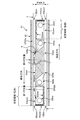
図2は、嵩回復装置20の概略側面図である。また、図3Aは、嵩回復装置20の主要部をなす加熱部60の説明図であり、図3Bは、図3A中のB−B断面図である。なお、図2及び図3Aでは、加熱部60の要部をなす加熱ユニット61を断面視で示している。また、図4は、加熱ユニット61のケース部材62の内部の詳細について説明する図である。なお、図4では、鉛直方向が図2と逆に示されている。
FIG. 2 is a schematic side view of the
図2に示すように、嵩回復装置20は、不織布原反3Rから不織布3を繰り出して所定の搬送経路に沿って搬送する搬送部30と、搬送経路の所定位置にて不織布3を加熱する加熱部60と、搬送部30及び加熱部60を制御するコントローラ(不図示)と、を有する。そして、加熱部60によって加熱されて嵩が回復された不織布3は、搬送方向の下流に位置するペットシート1に係る他の中間製品との合流点、例えば吸収体4との合流点へと送られて、当該合流点にて同中間製品に接合などされる。
As shown in FIG. 2, the
ちなみに、嵩回復装置20もそうであるが、製造ラインの各種装置(不図示)は、適宜な支持部材に支持されて同ラインに配置されている。そして、この例では、かかる支持部材の一例として、所謂鏡板(不図示)が使用されている。鏡板は、製造ラインの床部に鉛直に立設された板部材であり、同鏡板は、鉛直面(法線方向が水平方向を向いた面)を有し、当該鉛直面に各種装置が例えば片持ち状態で支持されている。
Incidentally, as with the
そして、以下では、この鉛直面の法線方向のことを「CD方向」と言う。なお、図2では、CD方向は、同図2の紙面を貫通する方向を向いており、より詳しくは、CD方向は、水平面内の任意の方向のうちで図2の紙面を貫通する方向を向いている。また、繰り出された不織布3は、基本的には、同不織布3の幅方向がCD方向を向いた姿勢で搬送されるため、不織布3の搬送方向は、CD方向と直交する任意の方向を向くことになる。なお、かかる支持部材は、何等鏡板に限るものではなく、これ以外の支持部材を用いても良い。
Hereinafter, the normal direction of the vertical plane is referred to as “CD direction”. In FIG. 2, the CD direction is a direction that penetrates the paper surface of FIG. 2. More specifically, the CD direction is a direction that penetrates the paper surface of FIG. 2 among arbitrary directions in the horizontal plane. It is suitable. Moreover, since the fed
(搬送部30)
搬送部30は、不織布3の搬送経路を規定する複数の搬送ローラー32,32…、及び繰り出し装置35を有する。
(Conveying unit 30)
The
各搬送ローラー32,32…は、CD方向に沿った回転軸回りに回転可能に支持されており、これにより、不織布3は、自身の幅方向をCD方向に向けた姿勢で搬送される。なお、搬送ローラー32,32…のうちの幾つかの搬送ローラー32,32は、駆動源としてのサーボモータにより駆動回転する駆動ローラー32u,32dであり、それ以外の搬送ローラー32,32…は、駆動源を有さない従動ローラー、すなわち、搬送される不織布3との接触により回転力を得て連れ回るローラーである。
Each of the
駆動ローラー32u,32dは、搬送経路における加熱部60(正確には、後述する加熱ユニット61)の両側の各位置にそれぞれ設けられている。そして、これら上流側駆動搬送ローラー32u及び下流側駆動搬送ローラー32dの回転動作を制御することにより、加熱部60での不織布3の搬送状態を調整することができる。
The driving rollers 32u and 32d are provided at respective positions on both sides of the heating unit 60 (more precisely, a
繰り出し装置35は、不織布原反3Rから不織布3を繰り出す装置であり、CD方向に沿った回転軸を有する。そして、当該回転軸に不織布原反3Rを回転可能に支持する。回転軸は、例えば駆動源としてのサーボモータ(不図示)によって駆動回転され、これにより、不織布原反3Rから不織布3を繰り出す。なお、繰り出し装置35が複数(例えば2つ)設けられ、複数(2つ)の不織布原反3Rを交互に切り替えて使用するのであっても良い。すなわち、一方の繰り出し装置35が不織布3を繰り出している間は、他方の繰り出し装置35は待機状態にあり、そして、一方の繰り出し装置35の不織布原反3Rが無くなったら、待機状態の繰り出し装置35が不織布3の繰り出しを開始するように構成されるのであっても良い。なお、かかる繰り出し装置35は周知なため、その詳細な説明については、省略する。
The
また、搬送部30は繰り出し装置35と上流側駆動搬送ローラー32uとの間に、アキュムレータ装置やテンションコントロール装置(共に不図示)を備えていても良い。アキュムレータ装置は、繰り出し装置35から繰り出された不織布3を搬送方向の下流へ払い出し可能に蓄積する装置である。例えば2つの繰り出し装置35で、一方の繰り出し装置35から不織布原反3Rの全ての不織布3を繰り出し、他方の繰り出し装置35へ切り替える際に繰り出し装置35が停止するような場合、アキュムレータ装置自身が蓄積している不織布3を下流に払い出すことによって、繰り出し装置35の繰り出し停止の影響を下流に及ぼさないようにすることができる。テンションコントロール装置は搬送される不織布3の張力の大きさ(N)が所定の目標値(N)になるように調整する装置である。
Further, the
(加熱部60)
加熱部60は、内部に不織布3を通過させながら不織布3に熱風を吹き付けて加熱する加熱ユニット61と、同加熱ユニット61に熱風を供給する熱風供給装置67と、を有する。
(Heating unit 60)
The heating unit 60 includes a
加熱ユニット61は、長手方向の両端部が開口したケース部材62と、ケース部材62の外に設けられ、ケース部材62内を不織布3が往復移動するように案内する複数の案内ローラー64,64,64と、を有する。そして、案内ローラー64,64,64によって、ケース部材62内には、不織布3の搬送経路の往路と復路とがそれぞれ直線状に形成されている。また、図3Aに示すように、ケース部材62の内部には不織布3の搬送方向に沿った壁面を形成する隔壁部材63が設けられる。この隔壁部材63(壁面)によって、ケース部材62内の空間は、往路用の空間SP62aと復路用の空間SP62bとに区画されている。すなわち、往路用の空間SP62aと復路用の空間SP62bとは、互いに空気の行き来が不能に隔離されている。また、この隔壁部材63による隔離によって、ケース部材62における長手方向の両端部のうちの一方の端部には、不織布3の往路用の入口62ainと復路用の出口62boutとの両者がそれぞれ形成されているとともに、他方の端部には、不織布3の往路用の出口62aoutと復路用の入口62binとの両者がそれぞれ形成されている。
The
隔壁部材63の両壁面63wa,63wbのうちで往路用の空間SP62aと隣接する壁面63wa(以下、往路用壁面63waとも言う)、及び、同両壁面63wa,63wbのうちで復路用の空間SP62bと隣接する壁面63wb(以下、復路用壁面63wbとも言う)は、それぞれ搬送方向及びCD方向と平行に設けられており、これにより、往路用壁面63wa及び復路用壁面63wbは、それぞれ不織布3の各面とほぼ平行とされている。そして、往路用壁面63waのうちで往路の搬送方向上流側の部分には、CD方向に長尺なスリット状の噴射口63Naが設けられており、また、復路用壁面63wbのうちで復路の搬送方向上流側の部分にも、CD方向に長尺なスリット状の噴射口63Nbが設けられている。そして、噴射口63Naは、隔壁部材63の内部に形成された圧力室R63aから供給される熱風を往路用の空間SP62aに噴射する。同様に、噴射口63Nbは、隔壁部材63の内部に形成された圧力室R63bから供給される熱風を復路用の空間SP62bに噴射する。
Out of the wall surfaces 63wa and 63wb of the
往路用壁面63waで、噴射口63Naが設けられた位置よりも搬送方向の下流側の領域には、図4に示されるような段差部63waeが設けられている。この段差部63waeによって、往路用の空間SP62aは搬送方向の下流側の部分で流路面積が拡張されている。すなわち、搬送方向を法線方向とする往路用の空間SP62aの断面積は、噴射口63Naが設けられた位置よりも搬送方向の下流側の領域において広くなっている。言い換えると、噴射口63Naが設けられた位置よりも搬送方向の下流側の第1の位置における空間SP62aの断面積が、搬送方向において噴射口63Naが設けられた位置と第1の位置との間の第2の位置における空間SP62aの断面積よりも大きくなっている。以下、この断面積が大きくなっている領域を拡張領域とも呼ぶ。 A stepped portion 63wae as shown in FIG. 4 is provided in the region on the downstream side in the transport direction from the position where the injection port 63Na is provided on the outbound wall surface 63wa. Due to the stepped portion 63wae, the flow path area of the forward path space SP62a is expanded at a downstream portion in the transport direction. That is, the cross-sectional area of the outward space SP62a having the normal direction as the conveyance direction is wider in a region downstream in the conveyance direction than the position where the injection port 63Na is provided. In other words, the cross-sectional area of the space SP62a at the first position downstream in the transport direction from the position at which the injection port 63Na is provided is between the position at which the injection port 63Na is provided and the first position in the transport direction. This is larger than the cross-sectional area of the space SP62a at the second position. Hereinafter, the region where the cross-sectional area is large is also referred to as an extended region.
また、段差部63waeの搬送方向の最下流側には出口部壁面63wasが設けられている。63wasは、往路用の空間SP62aの出口側の空間の一部を塞ぐように設けられる部材であり、当該63wasによって往路用の出口62aoutが形成されるとともに出口62aoutの大きさが規定される。また、往路用の空間SP62aのうち、段差部63waeと出口部壁面63wasとによって形成された空間の側部(ケース部材62の往路の拡張領域におけるCD方向の端部壁面)には、往路用の空間SP62内に噴射された熱風を外へ排出するための排出口63haが設けられている。なお、段差部63waeによって空間SP62aの断面積が拡張されている領域(往路の拡張領域)には、搬送方向に添った板状部材63wamが設けられていても良い(図4において点線で示されている)。板状部材63wamは表面に細かい孔を多数有する平面状の部材であり、当該孔を介して板状部材63wamの表面側から裏面側へ自在に気体を通過させることができる。嵩回復装置20を用いて不織布3の嵩回復を行う際には、不織布3が加熱されることによって繊維屑等の異物が発生する場合があるが、板状部材63wamの孔はそのような異物を通過させにくい。すなわち、板状部材63wamはフィルタのように機能して、熱風と共に異物が排出口63haから排出されるのを抑制する。63wamとしては例えばメッシュやパンチングメタル等を使用することができる。
In addition, an outlet wall surface 63was is provided on the most downstream side in the conveying direction of the stepped portion 63wae. 63was is a member provided to block a part of the space on the outlet side of the outward path space SP62a, and the 63was forms the outgoing path outlet 62aout and defines the size of the outlet 62aout. In addition, in the outward space SP62a, the side portion of the space formed by the step portion 63wae and the outlet wall surface 63was (the end wall surface in the CD direction in the extended region of the outward path of the case member 62) has an outward path. A discharge port 63ha for discharging the hot air injected into the space SP62 to the outside is provided. In addition, a plate-like member 63wam along the transport direction may be provided in an area where the cross-sectional area of the space SP62a is expanded by the stepped portion 63wae (outbound path expansion area) (indicated by a dotted line in FIG. 4). ing). The plate-like member 63wam is a planar member having many fine holes on the surface, and gas can freely pass through the holes from the front side to the back side of the plate-like member 63wam. When performing bulk recovery of the
同様に、復路用壁面63wbで、噴射口63Nbが設けられた位置よりも搬送方向の下流側の領域には、段差部63wbeが設けられ、復路用の空間SP62bは搬送方向の下流側の部分で流路面積が拡張されている。すなわち、搬送方向を法線方向とする復路用の空間SP62b断面積は、噴射口63Nbが設けられた位置よりも搬送方向の下流側の領域において広くなっている(復路の拡張領域)。また、段差部63wbeの搬送方向の最下流側には出口部壁面63wbsが設けられている。63wbsは、復路用の空間SP62bの出口側の空間の一部を塞ぐように設けられる板状の部材であり、当該63wbsによって復路用の出口62boutが形成されるとともに出口62boutの大きさが規定される。また、復路用の空間SP62bのうち、段差部63wbeと出口部壁面63wbsとによって形成された空間の側部(ケース部材62の復路側の拡張領域におけるCD方向の端部壁面)には、往路用の空間SP62内に噴射された熱風を外へ排出するための排出口63hbが設けられている。なお、段差部63wbeによって空間SP62bの断面積が拡張されている領域(復路の拡張領域)に、搬送方向に添った板状部材63wbmが設けられていても良い。63wbmは、上述した63wamと同様の機能を有する。 Similarly, on the return wall surface 63wb, a step portion 63wbe is provided in a region downstream of the position where the injection port 63Nb is provided in the transport direction, and the return path space SP62b is a downstream portion of the transport direction. The channel area is expanded. That is, the cross-sectional area of the return path space SP62b with the transport direction as the normal direction is wider in the downstream area in the transport direction than the position where the injection port 63Nb is provided (extended area of the return path). Further, an outlet wall surface 63wbs is provided on the most downstream side in the conveying direction of the step portion 63wbe. 63wbs is a plate-like member provided so as to block a part of the space on the outlet side of the return path space SP62b. The 63wbs forms the outlet 62bout for the return path and defines the size of the outlet 62bout. The Further, in the space SP62b for the return path, the side portion of the space formed by the step portion 63wbe and the outlet wall surface 63wbs (the end wall surface in the CD direction in the expansion region on the return path side of the case member 62) is used for the outward path. A discharge port 63hb is provided for discharging hot air injected into the space SP62 to the outside. In addition, the plate-shaped member 63wbm along the conveyance direction may be provided in a region where the cross-sectional area of the space SP62b is expanded by the step portion 63wbe (extended region of the return path). 63 wbm has the same function as 63 wam described above.
熱風供給装置67は、送風機67bと、ヒーター67hとを有する。そして、送風機67bで発生した風をヒーター67hで加熱することによって熱風を発生し、かかる熱風を適宜な管部材67pを介して前述の加熱ユニット61に係るケース部材62内の隔壁部材63の圧力室R63a,R63bに供給する。そして、同圧力室R63a,R63b経由で噴射口63Na,63Nbから熱風が噴射される。なお、圧力室R63a,R63bへの熱風の供給は、ケース部材62のCD方向の端部側から行われる。
The hot
送風機67bは、例えばモータを駆動源として回転するインペラ67iと、上述モータの回転数(rpm)を調整するインバータ(不図示)とを有する。そして、これにより、コントローラ(不図示)によるVVVFインバータ制御を行うことができて、その結果、インペラ67iの回転数(rpm)の変更を介して風量(m3/分)を任意値に調整可能である
The
なお、図3Aに示すように、ヒーター67hは送風機67bに内蔵されていても良いし、或いは、送風機67bの外部に設けられていても良い。ヒーター67hを外部に設ける場合には、図3A中に仮想的に二点鎖線で示すように、ヒーター67ha,67hbを加熱ユニット61のケース部材62に近接して配置すると良く、そうすれば、熱風の温度調整の際に、その応答性を高めることができる。また、その場合、さらに望ましくは、ヒーター67ha,67hbを噴射口63Na,63Nb毎にそれぞれ設けると良い。すなわち、往路用の噴射口63Naに対応させてヒーター67haを設け、また、これとは別に、復路用の噴射口63Nbに対応させてヒーター67hbを設けると良い。そして、このようにすれば、噴射口63Na,63Nb毎に個別に熱風の温度を調整することができて、その結果、嵩回復処理の条件設定をより精細に行えるようになる。
As shown in FIG. 3A, the
なお、かかるヒーター67,67ha,67hbとしては、電力(kW)で加熱する電気ヒーターを適用することができる。また、これに限るものではなく、風をなす空気を加熱可能なものであれば、適用可能である。
In addition, as this
また、この例では、「風」というのは、空気の流れのことを指しているが、広義には、空気の流れ以外に、窒素ガスや不活性ガスなどの気体の流れも含むものである。つまり、噴射口63Na,63Nbから窒素ガスなどを吹き付けても良い。 In this example, “wind” refers to the flow of air, but in a broad sense, it includes a flow of gas such as nitrogen gas or inert gas in addition to the flow of air. That is, nitrogen gas or the like may be blown from the injection ports 63Na and 63Nb.
また、本実施形態では、排出口63ha,63hbの出口部にそれぞれ回収用管部材69の一端側が接続され、回収用管部材69の他端側が送風機67bの吸い込み側部分67bsに連通している。これにより、空間SP62a,SP62bを流れた熱風が回収され、送風機67bの吸い込み側部分67bsへ戻される。回収された熱風は、外気を加えてヒーター67hによって加熱された後、再度加熱ユニット61へ供給される。熱風の回収を行なうことにより、加熱ユニット61において熱風が排出される際に近傍の他の中間製品へ悪影響を与えることを抑制しつつ、エネルギーの一部を再利用することができる。
In the present embodiment, one end side of the
本実施形態で、排出口63ha,63hbからの熱風の排出は、ケース部材62のCD方向の端部側から行われる。さらに、排出口63ha,63hbからの熱風の排出は、圧力室R63a,R63bに熱風が供給されるのと同じ側から行われる。つまり、本実施形態では、CD方向の一端側から加熱部61に熱風が供給され、同じ側から熱風が排出される。熱風供給用の管部材67pと、回収用管部材69とをCD方向の同じ側に接続することで配管の取り回しスペースを小さくすることができ、装置全体をコンパクトにまとめることができる。
In the present embodiment, the hot air is discharged from the discharge ports 63ha and 63hb from the end side of the
ちなみに、上述した板状部材63wam,63wbmが設けられない場合や、不織布3の繊維屑等の異物が小さいため板状部材63wam,63wbmを通り抜けてしまう場合には、当該異物が回収用管部材69を通って送風機67b内のヒーター67hへ送られて融着するおそれがある。そのため、望ましくは、送風機67bの吸い込み側部分67bsと回収用管部材69との間に、例えば所定メッシュの編み目状の異物吸い込み防止用フィルタ部材を介挿すると良い。なお、図3Aの例の場合についても、製造ライン内の紙粉等の異物が外気に混ざって、吸い込み側部分67bsから吸い込まれるおそれがあるので、望ましくは、吸い込み側部分67bsに同種のフィルタ部材を設けると良い。
Incidentally, when the plate-like members 63wam and 63wbm described above are not provided, or when foreign matter such as fiber scraps of the
また、図2及び図3の例では、加熱ユニット61は、ケース部材62の長手方向が水平方向を向いた横置きタイプとなっており、これにより、不織布3の搬送経路に係る往路及び復路を水平にしているが、何等これに限らない。すなわち、場合によっては、縦置きタイプにしても良い。より詳しくは、ケース部材62の長手方向を鉛直方向に向けて、これにより、不織布3の搬送経路に係る往路及び復路を鉛直にしても良い。また、さらに言えば、レイアウトの都合などに応じて、鉛直方向及び水平方向の両者からケース部材62の長手方向を傾けて配置しても良い。但し、縦置きタイプは、加熱ユニット61の設置に要する平面スペースが小さくて済むという点で優れている。
Moreover, in the example of FIG.2 and FIG.3, the
<不織布の嵩回復動作について>
加熱ユニット61のケース部材62の内部における不織布3の嵩回復動作について説明する。なお、本実施形態の往路用の空間SP62aと復路用の空間SP62bとはほぼ同様の構成を有し、ケース部材62の内部での熱風の流れ方や不織布3の嵩回復動作もほぼ同様である。したがって、以下の説明では主に往路用の空間SP62aについて説明し、復路用の空間SP62bについての説明は省略する場合がある。
<About bulk recovery operation of nonwoven fabric>
The bulk recovery operation of the
まず、熱風供給装置67から供給された熱風が、隔壁部材63に設けられた圧力室R63aに供給される。圧力室R63aの断面形状(CD方向を法線方向とする断面での形状)は、搬送方向の下流側に向かうに従って概ね細くなった先細り形状をなしており、その先細り形状の先端部にて、往路用の空間SP62aと連通しており、これにより、当該先端部が上述の噴射口63Naとして機能する。
First, the hot air supplied from the hot
往路用の噴射口63Naから噴射された熱風は、搬送方向の下流側の速度成分をもって不織布3の面に接触し、そのまま同面に沿って流れて行く(図4において、熱風の流れを太矢印で示している)。そして、搬送方向の上流側から搬送方向の下流側へ、図4における第2の位置及び第1の位置を通って流れる。不織布3の面を流れるように搬送方向に沿って熱風が移動するので、熱風が不織布3の厚さ方向から同不織布3を圧縮してしまう事態は有効に回避され、これにより、嵩の回復を円滑に行うことができる。
The hot air jetted from the outgoing jet port 63Na comes into contact with the surface of the
その際、熱風の風量(m3/分)の調整によって、不織布3の搬送速度値V3(m/分)よりも熱風の風速値Vw(m/分)の方を大きくすることができる。そして、そのようにすれば、各噴射口63Na,63Nbから噴射された熱風は、不織布3の面を滑るように不織布3を追い越して行って、最後に各排出口62ha,62hbから外に排出される。よって、熱風と不織布3との相対速度差に基づいて、当該熱風を乱流状態にすることができる。そして、その結果、熱伝達効率の飛躍的な向上を図れて、不織布3を効率良く加熱することができて、嵩が速やかに回復される。また、乱流状態の熱風によって不織布3の繊維がランダムにほぐされるので、これによっても、嵩の回復が促進される。
In that case, the wind speed value Vw (m / min) of hot air can be made larger than the conveyance speed value V3 (m / min) of the
ちなみに、熱風の風速値Vw(m/分)(以下、熱風の流速とも呼ぶ)は、例えば往路用の空間SP62a又は復路用の空間SP62bに供給される風量(m3/分)を、往路用の空間SP62a又は復路用の空間SP62bの断面積(つまり、搬送方向を法線方向とする断面の面積)で除算した値である。 Incidentally, the wind velocity value Vw (m / min) of hot air (hereinafter also referred to as the flow velocity of hot air) is, for example, the amount of air (m 3 / min) supplied to the outward space SP62a or the backward space SP62b. This is a value divided by the cross-sectional area of the space SP62a or the space SP62b for the return path (that is, the area of the cross section with the transport direction as the normal direction).
また、望ましくは、上述のような風速値Vwと搬送速度値V3との間の大小関係が、往路用又は復路用の各空間SP62a,SP62bの搬送方向の全長に亘って成立していると良いが、必ずしも全長に亘って成立している必要はない。すなわち、各空間SP62a,SP62bにおける一部についてでも、上記の大小関係が成立していれば、上記の乱流状態に係る作用効果を、相応に享受することができる。 Desirably, the magnitude relationship between the wind speed value Vw and the transport speed value V3 as described above is established over the entire length in the transport direction of the spaces SP62a and SP62b for the forward path or the return path. However, it does not necessarily have to be established over the entire length. That is, even in a part of each of the spaces SP62a and SP62b, if the above magnitude relationship is established, the operational effects relating to the turbulent state can be enjoyed accordingly.
なお、本実施形態では、搬送される不織布3が入口62ainからケース部材62の内部に入る際に、周囲(ケース部材62の外部)の空気の一部が巻き込まれて往路用の空間SP62aに進入する。そして、巻き込まれた空気は、搬送される不織布3に付き従って移動することにより搬送方向に流れる随伴流を形成する。この随伴流が搬送方向に沿って流れているため、噴射口63Naから噴射された熱風は、該随伴流に流されるようにして搬送方向に沿って流れやすくなる。
In the present embodiment, when the conveyed
また、往路用及び復路用の各噴射口63Na,63Nbの形状は、それぞれ、CD方向に長手方向が向いた長方形をなしている。そして、往路用の噴射口63NaのCD方向の寸法は、往路用の空間SP62aのCD方向の寸法と同値とされ、また復路用の噴射口63NbのCD方向の寸法は、復路用の空間SP62bのCD方向の寸法と同値とされているが、何等これに限らない。例えば、噴射口63Na,63Nbの方が小さくても良い。但し、望ましくは、各噴射口63Na,63NbのCD方向の寸法は、不織布3の幅方向の寸法(CD方向の寸法)よりも大きいと良く、このようにしていれば、CD方向の加熱ムラが抑制される。
また、各噴射口63Na,63Nbの短手方向の寸法(上記のCD方向の寸法と直交する方向の寸法)は、例えば、1mm〜10mmの範囲から任意値が選択されて設定される。
In addition, the shape of each of the outlets 63Na and 63Nb for the forward path and the return path is a rectangle whose longitudinal direction is in the CD direction. The dimension in the CD direction of the outward injection port 63Na is the same as the dimension in the CD direction of the outward path SP62a, and the dimension in the CD direction of the return injection port 63Nb is the same as that of the return space SP62b. Although it is set to the same value as the dimension in the CD direction, it is not limited to this. For example, the injection ports 63Na and 63Nb may be smaller. However, desirably, the dimension in the CD direction of each of the ejection ports 63Na and 63Nb is larger than the dimension in the width direction of the nonwoven fabric 3 (dimension in the CD direction). It is suppressed.
In addition, the dimension in the short direction of each of the ejection ports 63Na and 63Nb (the dimension in the direction orthogonal to the dimension in the CD direction) is set by selecting an arbitrary value from a range of 1 mm to 10 mm, for example.
さらに、望ましくは、噴射口63Na,63Nbの位置において熱風の噴射方向が不織布3の搬送方向に対してなす角度θが、0°〜30°の範囲内に入っていると良く、より望ましくは、0°〜10°の範囲内に入っていると良い(図3A)。そして、このようになっていれば、熱風を不織布3の面に沿わせて流しやすくなる。
Furthermore, the angle θ formed by the hot air injection direction with respect to the conveyance direction of the
ちなみに、図2の例では、加熱ユニット61は、ケース部材62の長手方向が水平方向を向いた横置きタイプとなっており、これにより、不織布3の搬送経路に係る往路及び復路を水平にしているが、何等これに限らない。すなわち、場合によっては、縦置きタイプにしても良い。より詳しくは、ケース部材62の長手方向を鉛直方向に向けて、これにより、不織布3の搬送経路に係る往路及び復路を鉛直にしても良い。また、さらに言えば、レイアウトの都合などに応じて、鉛直方向及び水平方向の両者からケース部材62の長手方向を傾けて配置しても良い。但し、縦置きタイプは、加熱ユニット61の設置に要する平面スペースが小さくて済むという点で優れている。
Incidentally, in the example of FIG. 2, the
<熱風の流速について>
加熱ユニット61においてケース部材62の内部に噴射される熱風の流速Vwを、不織布の搬送速度値V3よりも大きくする(つまり、Vw>V3とする)ことによって熱風を乱流状態にすることができ、それにより、不織布3において嵩の回復が促進されることを説明した。一方で、Vwが大きすぎると問題を生じる場合がある。以下では、Vwが大きい場合に生じる問題について、比較例を用いて説明する。
<About the flow velocity of hot air>
By making the flow velocity Vw of the hot air injected into the
図5は、比較例として従来型の加熱ユニット65のケース部材62の内部の詳細について説明する図である。比較例の加熱ユニット65の基本的な構成は、本実施形態の加熱ユニット61とほぼ同様であるが、隔壁部材63の形状が異なる。具体的に、比較例の加熱ユニット65では、隔壁部材63の往路用壁面63waにおいて段差部63waeが設けられていない。つまり、往路用壁面63waはケース部材の入口62ainから出口62aoutに亘って搬送方向に沿った平面形状であり、往路用の空間SP62aには拡張領域が存在しない。したがって、比較例の場合、往路用の空間SP62aの断面積は搬送方向の上流側から下流側に亘って一定である。断面積が一定であるので、往路用の空間SP62a内で流れる熱風の流速Vw(m/分)も搬送方向の上流側から下流側に亘ってほぼ一定の値となるはずである。
FIG. 5 is a diagram illustrating details of the inside of the
ところで、比較例の加熱ユニット65では、不織布3がケース部材62の内部を搬送される過程において、該織布3は熱風にさらされ続ける。言い換えると、ケース部材62の搬送方向上流側に設けられた噴射口63Naから噴射された熱風は、不織布3の表面に沿って搬送方向下流側へ流れ、その間、不織布3を加熱し続ける。つまり、不織布3は搬送方向の上流側から下流側へ搬送されるに従って累積的に熱量を加えられることになる。このようにして不織布3に大きな熱量が加えられると、不織布3は搬送方向に伸びやすくなる。図2で説明したように、不織布3は搬送方向に所定の大きさの張力(テンション)をかけられた状態で搬送されているため、加熱されることで繊維が柔らかくなった不織布3に対して張力が作用することで不織布3が搬送方向の両端側に引っ張られて伸びやすくなるからである。
By the way, in the
加熱ユニット65では、不織布3の表面に沿って搬送方向に流れる熱風が不織布3を搬送方向に引っ張る牽引力として作用するため、不織布3はより伸びやすくなる。特に、比較例では往路用の空間SP62a内で流れる熱風の流速Vwがほぼ一定であるため、噴射口63Naから噴射された熱風の流速Vwが大きい場合には、搬送方向の下流側における熱風の流速Vwも大きいままであり、この領域で不織布3を搬送方向に引っ張る牽引力も大きくなる。
In the
不織布3が搬送方向に引っ張られることによって伸びると、該不織布3の伸びた部分の表面において嵩が潰れやすくなるため、嵩回復の効果を十分に得ることができなくなる。また、不織布3が搬送方向に伸びるのに応じてCD方向の長さ(すなわち不織布の幅)が短くなるため、不織布3は製品としての基準サイズを満たさない不適合品となるおそれもある。
When the
したがって、比較例のような構造の加熱ユニット65では、熱風の流速Vwの大きさによっては正常な嵩回復を行なうことが困難となり、また、製品の品質が悪化するおそれがある。そのため、比較例では熱風の流速Vwの条件(上限速度)に制約を設ける必要が生じ、多様な動作条件に対応することが難しくなる。
Therefore, in the
これに対して、本実施形態の加熱ユニット61では、搬送方向下流側の領域での流速Vwを遅くすることにより、不織布3を伸びにくくすることが可能である。
On the other hand, in the
上述したように、本実施形態では隔壁部材63の搬送方向下流側の領域で段差部63waeが設けられ、当該領域において往路用の空間SP62aの断面積が拡張されている(上述した拡張領域)。図4において、往路用の空間SP62aの第1の位置における断面積(拡張後の断面積)をDad、往路用の空間SP62aの第2の位置における断面積(拡張前の断面積)をDauと定義し、また、往路用の空間SP62aの第1の位置における熱風の流速をVwad、往路用の空間SP62aの第2の位置における熱風の流速をVwauと定義すると、往路用の空間SP62aに噴射される熱風の単位時間当たりの流量が一定である場合、Dau・Vwau=Dad・Vwadの関係が成立する。なお、実際には空間SP62a内における圧力損失や熱損失が生じるが、全体に与える影響は軽微であるため、ここではそれらの影響は無視できるものとする。
As described above, in the present embodiment, the step portion 63wae is provided in the region downstream in the transport direction of the
本実施形態の場合、往路用の空間SP62aの断面積がDau<Dadの関係となることから、熱風の流速はVwau>Vwadとなる。つまり、搬送方向下流側の領域(第1の位置)での熱風の流速Vwadは、搬送方向上流側の領域(第2の位置)での熱風の流速Vwauよりも遅くなる。したがって、搬送方向下流側の拡張領域において熱風の流れによって不織布3を搬送方向に牽引する力は、比較例の場合よりも小さくなる。これにより、熱風による加熱の影響が大きい搬送方向下流側において不織布3が伸ばされにくくなり、嵩回復が正常に行なわれやすくなる。また、噴射口63Naから噴射された熱風の流速が大きい場合でも、拡張領域において流速を小さくすることができるため、熱風の流速の大きさに対する制約も少ない。
In the case of the present embodiment, since the cross-sectional area of the outbound space SP62a has a relationship of Dau <Dad, the flow velocity of the hot air is Vwau> Vwad. That is, the flow velocity Vwad of hot air in the downstream region (first position) in the transport direction is slower than the flow velocity Vwau of hot air in the upstream region (second position) in the transport direction. Therefore, the force which pulls the
さらに、本実施形態の加熱ユニット61では、空間SP62aの拡張領域中に排出口63haが設けられ、熱風を外に排出することができる。これにより、搬送方向の下流側の領域(拡張領域)において熱風の体積を減らすことができるため、熱風の流速をより小さくすることが可能となり、嵩回復動作を行う際の条件を調整しやすくなる。
Furthermore, in the
また、排出口63haは鉛直方向において、不織布3の搬送経路からずれた位置に設けられる。図4の例では、排出口63haは不織布3の搬送経路よりも鉛直方向上側に設けられている。仮に、排出口63haが鉛直方向において不織布3の搬送経路と同じ位置に設けられていたとすると、熱風が排出口63haから排出される際の流れによって搬送中の不織布3も排出口63haの方向(つまりCD方向の端部側)へ引き寄せられ、不織布3の正確な搬送動作を妨げるおそれがある。これに対して、本実施形態の排出口63haは不織布3の搬送経路からずれた位置に設けられているため、搬送動作の妨げにはなりにくい。
Further, the discharge port 63ha is provided at a position shifted from the conveyance path of the
さらに、本実施形態では、ケース部材62の内部に熱風を噴射する噴射口63Naと、ケース部材62の外部に熱風を排出する排出口63haとが共に、不織布3の搬送経路に対して鉛直方向の同じ側にずれた位置に設けられている。具体的に、図4の場合は噴射口63Na及び排出口63haが共に不織布の搬送経路に対して鉛直方向の上側にずれた位置に配置されている。噴射口63Naから空間SP62aに噴射された熱風は、不織布3の一方の面(図4において鉛直方向上面側の面)に沿って搬送方向上流側から下流側へ流れ、排出口63haから排出される。すなわち、熱風は不織布3を鉛直方向上下に貫通することなく、不織布3の一方の面(図4において鉛直方向上面側の面)に沿って搬送方向下流側に流れる。これにより、不織布3の一方の面が十分に加熱され、効率的に嵩回復を行うことができる。
Further, in the present embodiment, both the injection port 63Na that injects hot air into the
また、本実施形態では、空間SP62aの搬送方向最下流部に出口部壁面63wasが設けられ、該出口部壁面63wasによってケース部材62の出口62aoutが形成されている。図4から明らかなように、出口62aoutの断面積(搬送方向を法線方向とする断面の面積)は、拡張領域における断面積よりも小さくなっている。すなわち、本実施形態の往路用空間SP62aの断面積は、搬送方向上流側の領域(例えば図4の第2の位置)では狭く、搬送方向下流側の領域(例えば図4の第1の位置)で拡張され、搬送方向の最下流部(出口62aoutの位置)で再度狭くなっている。このように、出口の大きさを絞ることによって、該出口部分付近における熱風の流れを整流することができる。
In the present embodiment, the outlet wall surface 63was is provided at the most downstream portion in the transport direction of the space SP62a, and the outlet wall surface 63was forms an outlet 62aout of the
例えば、加熱部61の往路用の空間SP62aにおいて出口部壁面63wasが設けられていない場合、出口62aoutの断面積は、段差部63waeによって拡張された空間SP62aの断面積(上述した第1の位置における断面積Dadに相当)と同程度となり、図4の場合よりも大きくなる。出口62aoutの断面積が大きい場合、空間SP62aを流れる熱風は搬送方向下流側の拡張領域において搬送方向以外の方向にも広がり、そのまま出口62aout(若しくは排出口63ha)から排出される。つまり、熱風の流れに搬送方向以外の方向の速度成分が加わるため、熱風の流れに乱れが生じやすくなる。その影響で不織布3の搬送動作が乱されて、図4の鉛直方向やCD方向にばたつき等が生じやすくなり、安定した嵩回復が行なわれなくなるおそれがある。
For example, when the outlet part wall surface 63was is not provided in the outward space SP62a of the
これに対して、図4のように出口62aoutの断面積が狭くなっていれば、拡張領域において広がった熱風の流れが出口部分において絞られることによって流れが整流されるため、不織布3の搬送動作の乱れも解消され、安定した嵩回復動作を行いやすくなる。なお、熱風の流速Vwの大きさによっては、出口部壁面63wasが設けられていなくても不織布3の搬送動作の乱れが生じず、正常な嵩回復動作を行うことが可能な場合もある。
On the other hand, if the cross-sectional area of the outlet 62aout is narrow as shown in FIG. 4, the flow is rectified by the flow of the hot air spreading in the expansion region being throttled in the outlet portion, and therefore the conveying operation of the
また、熱風の流れ方向と不織布3の搬送方向とが平行に近いほど不織布3の搬送動作が安定しやすいことから、出口62aoutの鉛直方向位置は空間SP62aの搬送方向上流側の領域の位置に合わせておくことが望ましい。図4では、空間SP62aの出口62aoutの鉛直方向位置と入口62ainの鉛直方向位置とを合わせることにより、熱風が搬送方向に沿って直線状に流れやすくなるようにしている。
Moreover, since the conveyance operation of the
本実施形態では、ケース部材62の内部を上述のように構成することで、往路用の空間SP62a及び復路用の空間SP62bのそれぞれについて、搬送方向の下流側の領域(拡張領域)における熱風の流れを適当に調節することが可能となる。これにより、当該領域で不織布3が搬送に伸びてしまうことを抑制し、正確な嵩回復動作を実現することが可能となる。
In the present embodiment, the inside of the
===その他の実施の形態===
以上、本発明の実施形態について説明したが、上述の実施形態は、本発明の理解を容易にするためのものであり、本発明を限定して解釈するためのものではない。また、本発明は、その趣旨を逸脱することなく、変更や改良され得るとともに、本発明にはその等価物が含まれるのは言うまでもない。例えば、以下に示すような変形が可能である。
=== Other Embodiments ===
As mentioned above, although embodiment of this invention was described, the above-mentioned embodiment is for making an understanding of this invention easy, and is not for limiting and interpreting this invention. Further, the present invention can be changed or improved without departing from the gist thereof, and needless to say, the present invention includes equivalents thereof. For example, the following modifications are possible.
上述の実施形態では、嵩回復装置20の処理対象として、ペットシート1のトップシート3用の不織布3を例示したが、何等これに限らない。例えば、生理用ナプキンのトップシート用の不織布でも良いし、おむつのトップシート用の不織布でも良い。また、嵩回復装置20の処理対象は、何等トップシート3用の不織布3に限るものではない。すなわち、嵩高性が要求される他の部品の材料の不織布を、本発明の嵩回復装置20で処理しても良い。
In the above-described embodiment, the
上述の実施形態では、図1Bに示すように、トップシート3用の不織布3の一例として、片面に複数の直線状の突部3p,3p…を有した不織布3を例示したが、何等これに限らない。例えば、通常の形態の不織布、つまり両面が略平坦面の不織布であっても良い。
In the above-described embodiment, as illustrated in FIG. 1B, as an example of the
上述の実施形態では、図2に示すように、加熱部60の加熱ユニット61は、不織布3を往路及び復路の両者で加熱していたが、何等これに限らない。例えば、往路及び復路のどちらか一方だけでも嵩が十分回復する場合には、往路用の噴射口63Na及び復路用の噴射口63Nbのどちらか一方を省略しても良い。また、逆に、往路及び復路という2パスだけでは、嵩回復が不十分な場合には、上述の加熱ユニット61を一つではなく、複数設けて、不織布3を3パス以上で加熱しても良い。なお、往路及び復路のそれぞれに対応させて噴射口63Na,63Nbを設けた方が、嵩回復に必要な不織布3の搬送経路長をしっかりと確保しながらも、加熱ユニット61の長手方向の寸法の短尺化を図れるので、好ましい。
In the above-described embodiment, as illustrated in FIG. 2, the
上述の実施形態では、隔壁部材63の材料として、圧力室R63a,R63bや段差部63wae,63wbeによって形成される拡張領域以外の空間を内部に有さない中実部材を使用していたが、何等これに限るものではない。例えば、軽量化等の目的で、内部に空間を有した中空部材を用いても良い。中空部材の一例としては、例えば図3Aの往路用壁面63waをなすステンレス製の平板部材(不図示)と、復路用壁面63wbをなすステンレス製の平板部材(不図示)と、これら平板部材同士の間に介挿されてこれら平板部材同士を連結する角柱部材(不図示)と、を有した組み合わせ部材を例示できる。
In the above-described embodiment, as the material of the
上述の実施形態では、段差部63wae,63wbeによって、空間SP62a,SP62bがそれぞれ鉛直方向に拡張されていたが、空間SP62a,SP62bを拡張する方法は、何等これに限らない。例えば、空間SP62a,SP62bがそれぞれの搬送方向下流側の領域においてCD方向に拡張されるのであっても良い。CD方向に拡張された場合であっても当該領域において熱風の流速を小さくすることが可能であるため、不織布3が搬送方向に伸びることを抑制して正常な嵩回復動作を行うことができる。
In the above-described embodiment, the spaces SP62a and SP62b are expanded in the vertical direction by the stepped portions 63wae and 63wbe, but the method of expanding the spaces SP62a and SP62b is not limited to this. For example, the spaces SP62a and SP62b may be expanded in the CD direction in the areas downstream of the respective conveyance directions. Even in the case of expansion in the CD direction, it is possible to reduce the flow velocity of the hot air in the region, so that the
また、上述の実施形態では、空間SP62a,SP62bの断面積が段差部63wae,63wbeによって拡張される際に、空間SP62a,SP62bの搬送方向における断面形状が図4に示されるようなステップ状に拡張されていたが、何等これに限らない。例えば、段差部63wae,63wbeの代わりにテーパー部材(不図示)を設け、搬送方向の上流側から下流側に行くに従って空間SP62a,SP62bの断面積が徐々に大きくなるような形状としても良いし、空間SP62a,SP62bが複数段階で広がる形状やその他の形状としても良い。 In the above-described embodiment, when the cross-sectional areas of the spaces SP62a and SP62b are expanded by the step portions 63wae and 63wbe, the cross-sectional shape in the transport direction of the spaces SP62a and SP62b is expanded in a step shape as shown in FIG. However, it is not limited to this. For example, a tapered member (not shown) may be provided instead of the step portions 63wae and 63wbe, and the cross-sectional areas of the spaces SP62a and SP62b may gradually increase from the upstream side to the downstream side in the transport direction. The spaces SP62a and SP62b may have a shape that expands in a plurality of stages or other shapes.
1 ペットシート(吸収性物品)、
3 トップシート(不織布)、3R 不織布原反、
3a 面、3b 面、3e 外周縁部、
3t 溝部、3p 突部、3h 貫通孔、
4 吸収体、4c 吸収性コア、
4t1 被覆シート、4t2 被覆シート、
5 バックシート、
20 嵩回復装置、
30 搬送部、
32 搬送ローラー、
32u 上流側駆動搬送ローラー、32d 下流側駆動搬送ローラー、
35 繰り出し装置、
60 加熱部、61 加熱ユニット、62 ケース部材、
62ain 入口、62aout 出口、
62bin 入口、62bout 出口、
63 隔壁部材、
63Na 噴射口、63Nb 噴射口、
63ha 排出口、63hb 排出口、
63wa 往路用壁面、63wae 段差部、63wam 板状部材、
63was 出口部壁面、
63wb 復路用壁面、63wbe 段差部、63wbm 板状部材、
63wbs 出口部壁面
64 案内ローラー、
67 熱風供給装置、
67b 送風機、67bs 吸い込み側部分、
67h ヒーター、67ha ヒーター、67hb ヒーター、
67i インペラ、67p 管部材、69 回収用管部材、
SP62a 往路用の空間、SP62b 復路用の空間、
R63a 圧力室、R63b 圧力室
1 Pet sheet (absorbent article),
3 Top sheet (nonwoven fabric), 3R nonwoven fabric,
3a surface, 3b surface, 3e outer periphery,
3t groove, 3p protrusion, 3h through hole,
4 Absorber, 4c Absorbent core,
4t1 covering sheet, 4t2 covering sheet,
5 Backsheet,
20 Bulk recovery device,
30 transport section,
32 transport rollers,
32u upstream drive conveyance roller, 32d downstream drive conveyance roller,
35 feeding device,
60 heating units, 61 heating units, 62 case members,
62ain entrance, 62aout exit,
62 bin entrance, 62 bout exit,
63 Bulkhead member,
63Na injection port, 63Nb injection port,
63ha outlet, 63hb outlet,
63wa forward wall, 63wae step, 63wam plate member,
63was outlet wall surface,
63wb return wall surface, 63wbe stepped portion, 63wbm plate member,
63 wbs
67 Hot air supply device,
67b blower, 67bs suction side part,
67h heater, 67ha heater, 67hb heater,
67i impeller, 67p pipe member, 69 recovery pipe member,
SP62a Outbound space, SP62b Inbound space,
R63a pressure chamber, R63b pressure chamber
Claims (8)
前記搬送方向の両端部が開口されたケース部材を有し、
前記ケース部材の前記搬送方向の一端側の開口には前記不織布が搬送される際の入口が設けられ、前記ケース部材の前記搬送方向の他端側の開口には前記不織布が搬送される際の出口が設けられ、
前記ケース部材の前記入口側の部分には、前記出口側の部分に向けて前記ケース部材内の空間に前記熱風を噴射する噴射口が設けられ、
前記噴射口が設けられた位置よりも前記搬送方向の下流側の第1位置における前記ケース部材内の空間の断面積は、前記搬送方向において前記噴射口が設けられた位置と前記第1位置との間の第2位置における前記ケース部材内の空間の断面積よりも大きくなっており、
前記噴射口から噴射された前記熱風は、前記ケース部材内の空間において前記不織布の両面のうちの一方の面に接触しながら、前記搬送方向の上流側から前記搬送方向の下流側へ、前記第1位置及び前記第2位置を通って流れる、ことを特徴とする不織布の嵩回復装置。 An apparatus for recovering the bulk of the nonwoven fabric by blowing and heating hot air on the nonwoven fabric conveyed in the conveying direction,
Having a case member opened at both ends in the conveying direction;
An opening when the nonwoven fabric is conveyed is provided in an opening on one end side in the conveyance direction of the case member, and an opening when the nonwoven fabric is conveyed in an opening on the other end side in the conveyance direction of the case member. There is an exit,
The part on the inlet side of the case member is provided with an injection port for injecting the hot air into the space in the case member toward the part on the outlet side,
The cross-sectional area of the space in the case member in the first position downstream in the transport direction from the position where the spray port is provided is the position where the spray port is provided in the transport direction and the first position. Is larger than the cross-sectional area of the space in the case member in the second position between
The hot air ejected from the ejection port is in contact with one surface of both surfaces of the nonwoven fabric in the space in the case member, from the upstream side in the transport direction to the downstream side in the transport direction. A bulk recovery device for nonwoven fabric, which flows through the first position and the second position.
前記ケース部材内の空間で、前記第1位置を含み、前記第2位置よりも断面積が大きくなっている領域には、前記ケース部材内の空間に噴射された前記熱風を外に排出する排出口が設けられている、ことを特徴とする不織布の嵩回復装置。 It is a bulk recovery apparatus of the nonwoven fabric according to claim 1,
In the space in the case member that includes the first position and has a cross-sectional area larger than that of the second position, the hot air sprayed into the space in the case member is discharged to the outside. A non-woven fabric bulk recovery device characterized in that an outlet is provided.
前記排出口は、鉛直方向において前記不織布が搬送される経路からずれた位置に設けられている、ことを特徴とする不織布の嵩回復装置。 The bulk recovery apparatus for nonwoven fabric according to claim 2,
The non-woven fabric bulk recovery device, wherein the discharge port is provided at a position shifted from a path along which the non-woven fabric is conveyed in the vertical direction.
前記噴射口及び前記排出口は、共に前記不織布が搬送される経路に対して鉛直方向の同じ側にずれた位置に設けられている、ことを特徴とする不織布の嵩回復装置。 It is a bulk recovery apparatus of the nonwoven fabric according to claim 3,
The ejection port and the discharge port are both provided at a position shifted to the same side in the vertical direction with respect to a path along which the nonwoven fabric is conveyed.
前記ケース部材内の空間の前記搬送方向の最下流部には、前記ケース部材内の空間の出口側の空間の一部を塞ぐ部材が設けられている、ことを特徴とする不織布の嵩回復装置。 It is the bulk recovery apparatus of the nonwoven fabric in any one of Claims 2-4,
A non-woven fabric bulk recovery device characterized in that a member that closes a part of the space on the outlet side of the space in the case member is provided at the most downstream part in the transport direction of the space in the case member. .
前記ケース部材内に前記熱風を供給する熱風供給装置を備え、
前記熱風供給装置は、前記排出口から排出された前記熱風を回収して、前記ケース部材内に再度供給する、ことを特徴とする不織布の嵩回復装置。 A bulk recovery device for a nonwoven fabric according to any one of claims 2 to 5,
A hot air supply device for supplying the hot air into the case member;
The hot air supply device collects the hot air discharged from the discharge port and supplies the hot air again into the case member.
前記ケース部材の鉛直方向及び前記搬送方向とそれぞれ直行する方向であるCD方向を有し、
前記排出口からの前記熱風の排出と、前記ケース部材内への前記熱風の供給とが、前記ケース部材の前記CD方向の同じ側から行われる、ことを特徴とする不織布の嵩回復装置。 It is the bulk recovery apparatus of the nonwoven fabric of Claim 6, Comprising:
A CD direction that is a direction orthogonal to the vertical direction of the case member and the transport direction, respectively,
The nonwoven fabric bulk recovery apparatus, wherein the discharge of the hot air from the discharge port and the supply of the hot air into the case member are performed from the same side of the case member in the CD direction.
前記搬送方向の両端部が開口されたケース部材において、前記搬送方向の一端側の開口には前記不織布が搬送される際の入口が設けられ、前記搬送方向の他端側の開口には前記不織布が搬送される際の出口が設けられている場合に、前記ケース部材の前記入口側の部分に設けられた噴射口から、前記出口側の部分に向けて前記ケース部材内の空間に前記熱風を噴射する工程と、
前記噴射口が設けられた位置よりも前記搬送方向の下流側の第1位置における前記ケース部材内の空間の断面積が、前記搬送方向において前記噴射口が設けられた位置と前記第1位置との間の第2位置における前記ケース部材内の空間の断面積よりも大きくなっている前記ケース部材において、前記噴射口から噴射された前記熱風を前記不織布の両面のうちの一方の面と接触させながら、前記搬送方向の上流側から前記搬送方向の下流側へ、前記第1位置及び前記第2位置を通って流す工程と、
を有する、ことを特徴とする不織布の嵩回復方法。 A method for recovering the bulk of the non-woven fabric by blowing and heating hot air on the non-woven fabric conveyed in the conveying direction,
In the case member in which both ends in the transport direction are opened, an opening when the nonwoven fabric is transported is provided in the opening on one end side in the transport direction, and the nonwoven fabric is provided in the opening on the other end side in the transport direction. When the outlet is provided, the hot air is blown into the space in the case member from the injection port provided in the inlet side portion of the case member toward the outlet side portion. Spraying; and
The cross-sectional area of the space in the case member at the first position downstream in the transport direction with respect to the position at which the ejection port is provided is the position at which the ejection port is provided in the transport direction and the first position. In the case member that is larger than the cross-sectional area of the space in the case member at the second position between the hot air jetted from the jet port and one surface of the nonwoven fabric. While flowing from the upstream side in the transport direction to the downstream side in the transport direction through the first position and the second position;
A method for recovering the bulk of a non-woven fabric, comprising:
Priority Applications (4)
| Application Number | Priority Date | Filing Date | Title |
|---|---|---|---|
| JP2013217194A JP5728552B2 (en) | 2013-10-18 | 2013-10-18 | Non-woven fabric bulk recovery device and non-woven fabric bulk recovery method |
| CN201310560426.8A CN104514108B (en) | 2013-10-18 | 2013-11-12 | The volume recovery device of nonwoven fabric and the volume restoration methods of nonwoven fabric |
| US15/030,043 US9809913B2 (en) | 2013-10-18 | 2014-10-06 | Bulk recovery apparatus for nonwoven fabric and bulk recovery method for the same |
| PCT/JP2014/076719 WO2015056597A1 (en) | 2013-10-18 | 2014-10-06 | Device for recovering bulk of nonwoven cloth, and method for recovering bulk of nonwoven cloth |
Applications Claiming Priority (1)
| Application Number | Priority Date | Filing Date | Title |
|---|---|---|---|
| JP2013217194A JP5728552B2 (en) | 2013-10-18 | 2013-10-18 | Non-woven fabric bulk recovery device and non-woven fabric bulk recovery method |
Publications (2)
| Publication Number | Publication Date |
|---|---|
| JP2015078463A JP2015078463A (en) | 2015-04-23 |
| JP5728552B2 true JP5728552B2 (en) | 2015-06-03 |
Family
ID=52789964
Family Applications (1)
| Application Number | Title | Priority Date | Filing Date |
|---|---|---|---|
| JP2013217194A Active JP5728552B2 (en) | 2013-10-18 | 2013-10-18 | Non-woven fabric bulk recovery device and non-woven fabric bulk recovery method |
Country Status (4)
| Country | Link |
|---|---|
| US (1) | US9809913B2 (en) |
| JP (1) | JP5728552B2 (en) |
| CN (1) | CN104514108B (en) |
| WO (1) | WO2015056597A1 (en) |
Families Citing this family (1)
| Publication number | Priority date | Publication date | Assignee | Title |
|---|---|---|---|---|
| JP6843035B2 (en) * | 2017-11-30 | 2021-03-17 | ユニ・チャーム株式会社 | Non-woven fabric manufacturing method and non-woven fabric manufacturing equipment |
Family Cites Families (20)
| Publication number | Priority date | Publication date | Assignee | Title |
|---|---|---|---|---|
| US1670991A (en) * | 1925-04-25 | 1928-05-22 | Schilde Richard | Apparatus for drying fabrics and the like |
| US2700226A (en) * | 1950-04-21 | 1955-01-25 | Dungler Julien | Drying or like treatment apparatus for web material with fluid deflecting baffle means |
| DE1913261A1 (en) * | 1968-03-18 | 1969-10-02 | Singer Cobble Ltd | Device for drying web-shaped material |
| IT1093498B (en) * | 1977-03-30 | 1985-07-19 | Toray Industries | METHOD AND APPARATUS TO INTRODUCE A WIRE WITH MANY FILAMENTS |
| DE3603435C2 (en) * | 1986-02-05 | 1993-11-18 | Babcock Textilmasch | Arrangement for measuring the width tension in running webs |
| DE8817120U1 (en) * | 1988-04-07 | 1993-02-04 | Vits Maschinenbau Gmbh, 4018 Langenfeld | Device for heat treatment and/or drying of a material web |
| US4949441A (en) * | 1989-10-13 | 1990-08-21 | Ethridge Fredrick A | Polylaminar apparatus for fluid treatment of yarn |
| US5303484A (en) * | 1992-04-09 | 1994-04-19 | Thermo Electron Web Systems, Inc. | Compact convective web dryer |
| DE4226107A1 (en) * | 1992-08-07 | 1994-02-10 | Vits Maschinenbau Gmbh | Drying plant |
| US6397444B1 (en) * | 1994-05-24 | 2002-06-04 | University Of Manchester Institute Of Science & Technology | Apparatus and method for texturing yarn |
| US5511295A (en) * | 1995-03-15 | 1996-04-30 | E. I. Du Pont De Nemours And Company | System for preparing highly coherent air jet textured yarn |
| DE19605675C5 (en) * | 1996-02-15 | 2010-06-17 | Oerlikon Heberlein Temco Wattwil Ag | Process for aerodynamic texturing and texturing nozzle |
| JP4030484B2 (en) * | 2002-09-25 | 2008-01-09 | 花王株式会社 | Nonwoven fabric bulk recovery method |
| EP1403413B1 (en) * | 2002-09-25 | 2008-04-23 | Kao Corporation | Method for restoring bulkiness of nonwoven fabric |
| JP4352047B2 (en) * | 2003-03-04 | 2009-10-28 | 三菱レイヨン株式会社 | Heat treatment apparatus and heat treatment method for sheet-like material |
| US7556821B2 (en) | 2004-05-13 | 2009-07-07 | Alza Corporation | Apparatus and method for transdermal delivery of parathyroid hormone agents |
| JP5102610B2 (en) * | 2007-12-26 | 2012-12-19 | 花王株式会社 | Nonwoven fabric bulk control method |
| WO2010047292A1 (en) * | 2008-10-20 | 2010-04-29 | ユニ・チャーム株式会社 | Method of increasing thickness of nonwoven fabric and device therefor |
| JP5777558B2 (en) * | 2012-04-20 | 2015-09-09 | ユニ・チャーム株式会社 | Method and apparatus for restoring bulk of nonwoven fabric |
| JP5840100B2 (en) * | 2012-09-28 | 2016-01-06 | ユニ・チャーム株式会社 | Non-woven |
-
2013
- 2013-10-18 JP JP2013217194A patent/JP5728552B2/en active Active
- 2013-11-12 CN CN201310560426.8A patent/CN104514108B/en active Active
-
2014
- 2014-10-06 US US15/030,043 patent/US9809913B2/en active Active
- 2014-10-06 WO PCT/JP2014/076719 patent/WO2015056597A1/en not_active Ceased
Also Published As
| Publication number | Publication date |
|---|---|
| WO2015056597A1 (en) | 2015-04-23 |
| US9809913B2 (en) | 2017-11-07 |
| CN104514108B (en) | 2016-02-24 |
| JP2015078463A (en) | 2015-04-23 |
| CN104514108A (en) | 2015-04-15 |
| US20160251779A1 (en) | 2016-09-01 |
Similar Documents
| Publication | Publication Date | Title |
|---|---|---|
| JP5728555B2 (en) | Non-woven fabric bulk recovery device and bulk recovery method | |
| CN104499236B (en) | The manufacturing installation of absorbent commodity and the remodeling method of manufacturing installation | |
| JP6126968B2 (en) | Non-woven fabric bulk recovery device and bulk recovery method | |
| JP5728552B2 (en) | Non-woven fabric bulk recovery device and non-woven fabric bulk recovery method | |
| JP5753883B2 (en) | Manufacturing apparatus and manufacturing method of sheet-like member related to absorbent article | |
| JP5753884B2 (en) | Absorbent article manufacturing apparatus and manufacturing method | |
| JP5728553B2 (en) | Non-woven fabric bulk recovery device and non-woven fabric bulk recovery method | |
| JP6220811B2 (en) | Manufacturing apparatus and manufacturing method of sheet-like member related to absorbent article | |
| JP6286388B2 (en) | Absorbent article manufacturing apparatus and manufacturing method | |
| CN203700776U (en) | Non-woven fabric volume recovery device |
Legal Events
| Date | Code | Title | Description |
|---|---|---|---|
| A621 | Written request for application examination |
Free format text: JAPANESE INTERMEDIATE CODE: A621 Effective date: 20150126 |
|
| A871 | Explanation of circumstances concerning accelerated examination |
Free format text: JAPANESE INTERMEDIATE CODE: A871 Effective date: 20150126 |
|
| A975 | Report on accelerated examination |
Free format text: JAPANESE INTERMEDIATE CODE: A971005 Effective date: 20150212 |
|
| TRDD | Decision of grant or rejection written | ||
| A01 | Written decision to grant a patent or to grant a registration (utility model) |
Free format text: JAPANESE INTERMEDIATE CODE: A01 Effective date: 20150310 |
|
| A61 | First payment of annual fees (during grant procedure) |
Free format text: JAPANESE INTERMEDIATE CODE: A61 Effective date: 20150406 |
|
| R150 | Certificate of patent or registration of utility model |
Ref document number: 5728552 Country of ref document: JP Free format text: JAPANESE INTERMEDIATE CODE: R150 |
|
| R250 | Receipt of annual fees |
Free format text: JAPANESE INTERMEDIATE CODE: R250 |
|
| R250 | Receipt of annual fees |
Free format text: JAPANESE INTERMEDIATE CODE: R250 |
|
| R250 | Receipt of annual fees |
Free format text: JAPANESE INTERMEDIATE CODE: R250 |
|
| R250 | Receipt of annual fees |
Free format text: JAPANESE INTERMEDIATE CODE: R250 |
|
| R250 | Receipt of annual fees |
Free format text: JAPANESE INTERMEDIATE CODE: R250 |
|
| R250 | Receipt of annual fees |
Free format text: JAPANESE INTERMEDIATE CODE: R250 |
|
| R250 | Receipt of annual fees |
Free format text: JAPANESE INTERMEDIATE CODE: R250 |
|
| R250 | Receipt of annual fees |
Free format text: JAPANESE INTERMEDIATE CODE: R250 |
|
| R250 | Receipt of annual fees |
Free format text: JAPANESE INTERMEDIATE CODE: R250 |