JP5721683B2 - Dust remover for air conditioner and air conditioner - Google Patents
Dust remover for air conditioner and air conditioner Download PDFInfo
- Publication number
- JP5721683B2 JP5721683B2 JP2012224134A JP2012224134A JP5721683B2 JP 5721683 B2 JP5721683 B2 JP 5721683B2 JP 2012224134 A JP2012224134 A JP 2012224134A JP 2012224134 A JP2012224134 A JP 2012224134A JP 5721683 B2 JP5721683 B2 JP 5721683B2
- Authority
- JP
- Japan
- Prior art keywords
- dust
- air conditioner
- filter
- vehicle
- air
- Prior art date
- Legal status (The legal status is an assumption and is not a legal conclusion. Google has not performed a legal analysis and makes no representation as to the accuracy of the status listed.)
- Active
Links
- 239000000428 dust Substances 0.000 title claims description 122
- 238000011144 upstream manufacturing Methods 0.000 claims description 6
- 238000001914 filtration Methods 0.000 description 26
- 238000004140 cleaning Methods 0.000 description 10
- 230000001877 deodorizing effect Effects 0.000 description 8
- 238000004804 winding Methods 0.000 description 7
- 230000010354 integration Effects 0.000 description 6
- 238000004378 air conditioning Methods 0.000 description 5
- 235000019645 odor Nutrition 0.000 description 5
- 230000000694 effects Effects 0.000 description 4
- 238000012423 maintenance Methods 0.000 description 4
- 238000009825 accumulation Methods 0.000 description 2
- 238000007599 discharging Methods 0.000 description 2
- AMWRITDGCCNYAT-UHFFFAOYSA-L hydroxy(oxo)manganese;manganese Chemical compound [Mn].O[Mn]=O.O[Mn]=O AMWRITDGCCNYAT-UHFFFAOYSA-L 0.000 description 2
- 239000000463 material Substances 0.000 description 2
- 238000000034 method Methods 0.000 description 2
- 230000035699 permeability Effects 0.000 description 2
- 239000003507 refrigerant Substances 0.000 description 2
- 230000000844 anti-bacterial effect Effects 0.000 description 1
- 244000052616 bacterial pathogen Species 0.000 description 1
- 239000003054 catalyst Substances 0.000 description 1
- 230000001143 conditioned effect Effects 0.000 description 1
- 239000000470 constituent Substances 0.000 description 1
- 238000010276 construction Methods 0.000 description 1
- 238000001816 cooling Methods 0.000 description 1
- 238000005034 decoration Methods 0.000 description 1
- 230000007423 decrease Effects 0.000 description 1
- 238000007791 dehumidification Methods 0.000 description 1
- 230000002542 deteriorative effect Effects 0.000 description 1
- 239000000835 fiber Substances 0.000 description 1
- 238000010438 heat treatment Methods 0.000 description 1
- 238000003780 insertion Methods 0.000 description 1
- 230000037431 insertion Effects 0.000 description 1
- 238000009434 installation Methods 0.000 description 1
- 238000002955 isolation Methods 0.000 description 1
- 230000002093 peripheral effect Effects 0.000 description 1
- 238000007790 scraping Methods 0.000 description 1
- 238000000926 separation method Methods 0.000 description 1
Images


Description
本発明は、空気調和装置の吸気口の上流に設置され、吸気空気から塵埃を除去するための空気調和装置用の除塵装置、及び、その除塵装置を備えた空気調和装置に関するものである。 The present invention relates to a dust remover for an air conditioner that is installed upstream of an intake port of an air conditioner and removes dust from intake air, and an air conditioner including the dust remover.
この種の空気調和装置用の除塵装置として、従来の鉄道車両用の空気調和装置の除塵装置では、除塵用のフィルターを巻取り式とし、除塵能力が低下したら巻き取って新しい面を供給し、メンテナンスの長期化を図っている。このような除塵装置では、半年程度でフィルターが巻き終わり、巻き終わると、フィルターの取外し、清掃、巻き戻しが必要になる。 As a dust remover for this type of air conditioner, in the dust remover of the conventional air conditioner for railway vehicles, the filter for dust removal is a take-up type, and when the dust removal capability is reduced, it is wound up to supply a new surface, The maintenance is extended. In such a dust removing device, it is necessary to remove, clean and rewind the filter after the filter has been wound and wound in about six months.
また、巻き取り式のフィルター装置として、「空調機用ダクトの空気吸い込み口の前面に、前記空気吸い込み口を覆うように設けられた、フッ素樹脂系繊維製のフィルター本体を有する無端連続移動式フィルターと、前記無端連続移動式フィルターの前記フィルター本体を間に挟み、その両面に接触するように設けられた、前記フィルター本体の移動方向とは反対の方向に回転する1対のブラシロールとを備えた」ものが提案されている(例えば、特許文献1参照)。 Further, as a wind-up type filter device, “an endless continuous moving filter having a filter body made of a fluororesin-based fiber provided on the front surface of an air suction port of an air conditioner duct so as to cover the air suction port” And a pair of brush rolls that are provided so as to be in contact with both sides of the filter body of the endless continuous moving filter and that rotate in a direction opposite to the moving direction of the filter body. Have been proposed (for example, see Patent Document 1).
さらに、「空気調和機の室内機の吸い込み口に設けたフィルタと、前記フィルタを覆い、前記吸い込み口に固定するカバー部材と、前記フィルタと前記カバー部材との間に設けられた掃除ノズルと、を備えた空気調和機の清掃機構であって、前記掃除ノズルがフィルタ側に吸い込み口を、反対側に真空源の接続口を有し、前記吸い込み口と前記差し込み口との間に前記吸い込み口を中心として回転自在な連結部を備え、前記掃除ノズルを回転させるための駆動機構を備えている」ものが提案されている(例えば、特許文献2参照)。 Furthermore, "a filter provided at the suction port of the indoor unit of the air conditioner, a cover member that covers the filter and is fixed to the suction port, a cleaning nozzle provided between the filter and the cover member, A cleaning mechanism for an air conditioner, wherein the cleaning nozzle has a suction port on the filter side and a connection port for a vacuum source on the opposite side, and the suction port is located between the suction port and the insertion port. Has been proposed (for example, see Patent Document 2).
鉄道車両用の空気調和装置に設けられたフィルターには空気中から集塵した塵埃が付着する。この塵埃の堆積量が多くなると空気の通過が悪くなり空調効率が低下する。そのため、従来の除塵装置ではロール状フィルターを自動で巻き取って新しい面を供給し、フィルターの濾過能力が過渡に低下しないようにしてメンテナンスの長期化を図っている。しかしながら、このような除塵装置では、半年程度でフィルターが巻き終わるため、フィルターの取外し、清掃、巻き戻しといったメンテナンスの労力を必要とし、更なるフィルターのメンテナンスまでの期間の長期化が課題である。また、設置スペースや巻取機構などを考慮しなければならず、単純にフィルターを長くすればいいというわけでもない。 Dust collected from the air adheres to a filter provided in an air conditioner for a railway vehicle. If the amount of accumulated dust increases, the passage of air deteriorates and air conditioning efficiency decreases. For this reason, the conventional dust remover automatically rolls up the roll filter to supply a new surface, so that the filtering ability of the filter is not lowered transiently, thereby extending the maintenance. However, in such a dust removing device, the filter finishes winding in about half a year, so that maintenance work such as removal, cleaning, and rewinding of the filter is required, and it is a problem to extend the period until further filter maintenance. Also, the installation space and the winding mechanism must be taken into account, and it is not simply a matter of lengthening the filter.
また、特許文献1に記載の技術では、フィルターを挟んで対向する1対のブラシによりフィルターに付着した物体を除去するようにしている。しかしながら、フィルターとブラシとが点で接触するため、ブラシによる物体の掻き取り面が実質的に小さく、除塵が効率的ではなかった。
In the technique described in
さらに、特許文献2に記載の技術のように掃除ノズルを回転させてフィルターを清掃するものでは、ノズルが円軌道を描くため、一般的に四角い形状のフィルターの角部の塵埃を除去することは不可能である。特に、設備用や車両用の空気調和装置においては、処理風量が多く、フィルターの面積を大きくする必要があるため、これに伴いノズルを大きく構成したり、ノズルを複数設置したりする必要があり、装置サイズや質量、施工性、動作の信頼性等々において課題が生じる。
Further, in the case of cleaning the filter by rotating the cleaning nozzle as in the technique described in
本発明は、以上のような課題を解決するためになされたもので、フィルター体の面積を確保しつつ、フィルター体に付着した塵埃を効率良く除去できる小形で施工性の良好な空気調和装置用の除塵装置、及び、その除塵装置を備えた空気調和装置を提供するものである。 The present invention has been made to solve the above-described problems, and is used for an air conditioner having a small size and good workability that can efficiently remove dust adhering to the filter body while securing the area of the filter body. The present invention provides a dust removing device and an air conditioner equipped with the dust removing device.
本発明に係る空気調和装置用の除塵装置は、空気調和装置の吸気口の上流に設置され、吸気空気から塵埃を除去するための空気調和装置用の除塵装置において、モーターによって駆動される駆動軸と、前記駆動軸に従動して回転される従動軸と、前記駆動軸と前記従動軸との間に架け渡され、前記駆動軸の回転により移動可能な無端帯状のフィルター体と、先端に形成された開口部の少なくとも一部が前記フィルター体の湾曲する部分に対向する吸込ノズルと、前記吸込ノズルから吸引した塵埃を蓄積する集塵部と、前記集塵部の下流側において前記吸込ノズルに吸引力を与える電動送風機と、を備え、前記駆動軸及び前記従動軸によって前記フィルター体は湾曲されるようになっており、前記吸込ノズルは、前記開口部の少なくとも一部が前記駆動軸又は前記従動軸によって湾曲されている前記フィルター体に沿って配置されているものである。 A dust remover for an air conditioner according to the present invention is installed upstream of an air inlet of an air conditioner, and is a drive shaft driven by a motor in a dust remover for an air conditioner for removing dust from intake air. And a driven shaft that is rotated by following the drive shaft, an endless belt-like filter body that is spanned between the drive shaft and the driven shaft and is movable by the rotation of the drive shaft, and formed at the tip A suction nozzle in which at least a part of the opened opening opposes the curved portion of the filter body, a dust collecting part for accumulating dust sucked from the suction nozzle, and the suction nozzle downstream of the dust collecting part. and a electric blower providing a suction force, the filter body by said drive shaft and said driven shaft being adapted to be bent, said suction nozzle, at least a portion of said opening Serial in which are disposed along said filter body being bent by the drive shaft or the driven shaft.
本発明に係る空気調和装置用の除塵装置によれば、移動可能な無端帯状のフィルター体の面積を確保しつつ、フィルター体に付着した塵埃を効率良く除去できる小形で施工性の良好なものとなる。 According to the dust removing device for an air conditioner according to the present invention, the compact and good workability can efficiently remove dust adhering to the filter body while securing the area of the movable endless belt-like filter body. Become.
以下、図面に基づいてこの発明の実施の形態について説明する。本実施の形態では、車両内の空調を行う車両用空気調和装置に除塵装置を適用する例を説明するが、除塵装置が適用される空気調和装置は車両用のものに限られたものではない。なお、図1を含め、以下の図面では各構成部材の大きさの関係が実際のものとは異なる場合がある。また、図1を含め、以下の図面において、同一の符号を付したものは、同一又はこれに相当するものであり、このことは明細書の全文において共通することとする。さらに、明細書全文に表わされている構成要素の形態は、あくまでも例示であって、これらの記載に限定されるものではない。 Embodiments of the present invention will be described below with reference to the drawings. In this embodiment, an example in which a dust removing device is applied to a vehicle air conditioner that performs air conditioning in a vehicle will be described. However, the air conditioner to which the dust removing device is applied is not limited to that for a vehicle. . In addition, in the following drawings including FIG. 1, the relationship of the size of each component may be different from the actual one. Further, in the following drawings including FIG. 1, the same reference numerals denote the same or equivalent parts, and this is common throughout the entire specification. Furthermore, the forms of the constituent elements shown in the entire specification are merely examples, and are not limited to these descriptions.
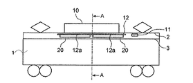
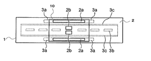
図1は、本発明の実施の形態に係る空気調和装置用の除塵装置(以下、除塵装置20と称する)を備えた車両1の側面の概略透視図である。図2は、図1の車両1の吸気口(天井吸気口2a)及び排気口(天井排気口2b)を示す図で、図1の一部透視した概略平面図に相当する。図3は、図1のA−A概略断面図である。なお、以下において車両1の長さ方向とは図2の左右方向に相当し、車両1の幅方向とは図2の上下方向に相当するものとする。
FIG. 1 is a schematic perspective view of a side surface of a
図1に示すように、車両1の上方側の車両外部には、車両1内の空調を行う車両用空気調和装置10が配設されている。車両1の天井2には、図2に示すように、車両用空気調和装置10の吸気口(図示省略)に連通する天井吸気口2aと、車両用空気調和装置10の排気口(図示省略)に連通する天井排気口2bとが開口されている。天井吸気口2aは、車両1の幅方向の両端側に車両1の長さ方向に延びるようにして形成されている。また、天井排気口2bは、車両1の長さ方向及び幅方向の略中心部に、幅方向に所定の間隔を空けてここでは2箇所に形成されている。
As shown in FIG. 1, a
図1に示すように、車両1の上方側の車両内部には、車両1の天井2から下方に所定の距離で離間して化粧パネル3が配置されており、天井吸気口2a及び天井排気口2bは、化粧パネル3の影に隠れて乗客からは見えない位置に形成されている。化粧パネル3には、天井吸気口2aに連通する車内吸気口3aと、天井排気口2bに連通する車内排気口3bと、天井排気口2bに連通する車内補助排気口3cとが形成されている。
As shown in FIG. 1, a
車内吸気口3aは、車両1の幅方向の両端部のそれぞれに、車両1の長さ方向に2箇所配置され、ここでは計4箇所形成されている。また、車内排気口3bは、車両1の幅方向の中心部に、車両長さ方向に所定の間隔を空けて複数形成されている(図2では6箇所)。さらに、車内補助排気口3cは、車両1の長さ方向に延びるようにして車内排気口3bの車両幅方向の両側に2箇所形成されている。
The
車両用空気調和装置10は、図3の矢印に示すように、車両1内の空気を車内吸気口3a及び天井吸気口2aを介して車両用空気調和装置10の吸気口から吸気し、吸気した空気を天井排気口2b、車内排気口3b及び車内補助排気口3cを介して車両1内へと吹き出すようになっている。車両用空気調和装置10は、このようにして車両1内の空気を循環させながら車両1内の空調を行う。なお、車両用空気調和装置10は、圧縮機、凝縮器、絞り装置、蒸発器を配管接続した冷媒回路と、凝縮器及び蒸発器を流れる冷媒と熱交換させる空気をこれらに供給する送風機と、を少なくとも有している。
As shown by the arrows in FIG. 3, the
また、化粧パネル3の天井2側には車両用空気調和装置10の制御装置11が配置されている。制御装置11は、例えばマイコンで構成され、車両用空気調和装置10の全体の制御を行うとともに、除塵装置20の駆動制御も行う。制御装置11は、車両用空気調和装置10の稼動時間を計時して稼働積算時間を保持する計時部(図示省略)と、後述のフィルター22の巻き取り動作回数を検知して計数するカウンタ(図示省略)と、を少なくとも有している。
A
また、車内吸気口3aから天井吸気口2aに至る風路には、車両用空気調和装置10の吸気口に向かう吸気空気から塵埃を濾過して捕集し、清浄な空気を車両用空気調和装置10に供給するための除塵装置20が配置されている。天井2の車両1側には、車両用空気調和装置10の吸気口に向かう空気が通過する開口部12aが車内吸気口3aに対応して車両長さ方向に2箇所形成された取付枠12が車両幅方向の両端部に2枚固定されている。この各取付枠12のそれぞれに、各開口部12aに対応して除塵装置20が着脱自在に取り付けられている。
Further, in the air path from the vehicle
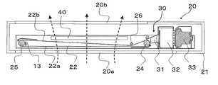
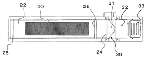
図4は、図1の除塵装置20の拡大概略断面図で、図3のB−B断面図に相当する。図5は、図4の平面図である。図6は、図4の塵埃除去機構部分を拡大して示す側面断面図である。図7は、図6のC−C断面図である。図4〜図7に基づいて、除塵装置20について説明する。
4 is an enlarged schematic cross-sectional view of the
除塵装置20は、吸気口20a及び排気口20bを有する筐体21内に、無端帯状の、例えばサラン材からなるメッシュ地のフィルター(フィルター体)22と、駆動軸24を回転することでフィルター22を移動させる駆動手段としてのモーター23と、フィルター22に付着した塵埃を除去する塵埃除去機構30と、脱臭フィルター40とを備えている。なお、図7に示すように、モーター23と駆動軸24とは、タイミングベルト41により連結しており、タイミングベルト41を介してモーター23の回転力を駆動軸24に伝達する構成としている。
The
フィルター22は、モーター23によって駆動される駆動軸24と、駆動軸24に従動して回転される従動軸25との間に架け渡されており、モーター23によって駆動軸24が回転すると、その回転に伴って図4の実線矢印方向に移動する。また、駆動軸24と従動軸25との中間にアイドラー26を備えており、このアイドラー26によってフィルター22には適度な張力が掛けられた状態とし、駆動軸24および従動軸25の空転を防ぐ構造としている。
The
モーター23は、車両用空気調和装置10の制御装置11(図1参照)に電気的に接続され、制御装置11により駆動制御される。また、従動軸25には、従動軸25が所定量の回転を行ったか否かを検出する回転検出器13が取り付けられている。回転検出器13は、従動軸25が所定量の回転を行っている間、信号を出力し、所定量の回転が終了すると、信号出力を停止するものである。制御装置11は、回転検出器13からの信号が得られなくなったことに応答してモーター23の回転を停止する。
The
フィルター22には、図4の点線矢印に示す方向に車内空気が通過するようになっており、フィルター22は車内空気の通過方向に直交する図4の実線矢印方向に移動する。フィルター22の上流側の一方の面は、吸気口20aから流入した車内空気から塵埃を濾過して捕集する濾過領域面22aとなっている。濾過領域面22aは、吸気口20aの開口面積に略一致するように構成されている。フィルター22の下流側の他方の面は、捕集された塵埃が除去される塵埃除去済み面(掃除面)22bとなっている。そして、フィルター22の塵埃除去済み面22b側には、濾過領域面22aに付着した塵埃を除去するための塵埃除去機構30が配置されている。
The vehicle interior air passes through the
塵埃除去機構30は、フィルター22が塵埃除去機構30を通過することによってフィルター22に付着した塵埃を除去するものである。以下、塵埃除去機構30の構成について説明する。
The
塵埃除去機構30は、フィルター22に堆積した塵埃をフィルター22から除去するための吸込ノズル31と、吸込ノズル31から吸引した塵埃を蓄積する集塵部32と、吸込ノズルに吸引力を与える電動送風機部33とを備えている。
The
吸込ノズル31は、電動送風機部33からの吸引力によりフィルター22から除去した塵埃をその内部に取り入れる開口部31aが先端に形成されている。また、図5に示したように、吸込ノズル31は、フィルター22の略全幅に亘って設置されている。さらに、吸込ノズル31の先端は、図6に示すように断面視した状態において、フィルター22の湾曲形状に対応して湾曲されており、開口部31aがフィルター22の湾曲する部分に沿った形状になっている。ここで、吸込ノズル31の開口部31aの少なくとも一部を、フィルター22が湾曲する部分に所定の間隔を設けて対向するように配置している。また、吸込ノズル31は、駆動軸24の外周面に開口部31aの少なくとも一部が対向するように配置されている。
The
集塵部32は、吸込ノズル31を介して吸引した塵埃を回収するものであり、集塵ケース32aと、ケース蓋32bと、集塵ケース32aの内部に設置された紙パック32cとから構成される。ケース蓋32bは、集塵ケース32aに対して回動可能に軸支されており、客室側からケース蓋32bを開けることにより、紙パック31cを取り出せる構成としている。
The
電動送風機部33は、電動送風機33aと、内部に電動送風機33aを収容する電動送風機ケース33b、動作時の振動を抑制する機能を持ち、電動送風機33aを電動送風機ケース33bに対して保持する前防振ゴム33c及び後防振ゴム33dと、を備えている。また、電動送風機33aからの排気を排出する電動送風機排気口33eを電動送風機ケース33bに形成している。
The
脱臭フィルター40は、例えば酸化マンガン系の触媒フィルターで構成されており、筐体21の排気口20bとフィルター22との間に配置され、車両用空気調和装置10の吸気口に吸気される前の吸気空気の臭気を除去するものである。脱臭フィルター40は、図4及び図5に示すように、フィルター22の濾過領域面22aの略半分に相当する面を覆う大きさに形成されている。濾過領域面22aの全体を脱臭フィルター40で覆ってしまうと、通気性の低下を招くことから、ここでは略半分に相当する面を覆うようにしている。これにより、塵埃除去能力と臭気除去効果の両方を得ることを可能としている。
The
次に、車両用空気調和装置10、除塵装置20の動作を説明する。
制御装置11により車両用空気調和装置10が駆動されると、車両1内の空気が車内吸気口3a、除塵装置20及び天井吸気口2aを介して車両用空気調和装置10の内部に取り込まれる。この際、車内空気中に含まれる塵埃は除塵装置20により除去され、清浄な空気が車両用空気調和装置10内に流入する。車両用空気調和装置10内に流入した空気は、車両用空気調和装置10内で空調空気とされる。そして、車両用空気調和装置10から排出された後、天井排気口2b、車内排気口3b及び車内補助排気口3cを介して車両1内に吹き出される。
Next, operations of the
When the
除塵装置20では、吸気口20aから筐体21内に流入した車内空気が、まずフィルター22の濾過領域面22aを通過する。車内空気は、そこに含まれている塵埃が濾過領域面22aで濾過されて清浄な空気となり、その後、脱臭フィルター40を通過して臭気が取り除かれた後、排気口20bから車両用空気調和装置10に向かって排出される。このように、車内空気が除塵装置20、車両用空気調和装置10及び車両1内を循環することにより、濾過領域面22aには徐々に塵埃が堆積していくことになる。
In the
制御装置11は、車両用空気調和装置10の動作開始後、計時部により車両用空気調和装置10の稼動時間を計時しており、計時部で計時した稼動積算時間が予め設定された規定積算時間(例えば20時間)に達すると、モーター23および電動送風機33aに対して駆動指令を発する。
After the operation of the
制御装置11から駆動指令が発せられると、モーター23は駆動軸24を所定数回転させる。具体的には、制御装置11は駆動指令を出力後、従動軸25に設けた回転検出器13の信号が帰ってくる間だけ駆動軸24を回転させる。これにより、フィルター22が所定量送られ、濾過領域面22aが塵埃除去機構30を通過し、濾過領域面22aに付着した塵埃が除去されて塵埃除去済み面22bとなる一方、フィルター22の下流側に位置していた塵埃除去済み面22bが上流側に移動し、新たな濾過領域面22aとして再使用される。
When a drive command is issued from the
塵埃除去機構30による塵埃除去動作は上述の通りであり、制御装置11からの駆動指令によって駆動軸24が回転すると、駆動軸24の回転に伴い濾過領域面22aが吸込ノズル31側へ移動する。この際、電動送風機33aにより吸込ノズル31には吸引力が発生しているが、開口部31aを、濾過領域面22aを挟んで駆動軸24と対向するように配置している。そのため、吸込ノズル31内の真空度が高くなっており、濾過領域面22aの表面側及び内面側および目地に付着した塵埃を効率良く取り除くことができる。これは、駆動軸24の表面の大部分が濾過領域面22aの内面側に接しているためである。逆に、開口部31aを、濾過領域面22aの内面側に構造物が存在しない箇所に設置した場合には、フィルター22は当然ながら通気性を持つために、吸込ノズル31内の真空度が殆ど高まることはなく、塵埃を効率良く除去することができない。
The dust removal operation by the
吸込ノズル31から吸引した塵埃は、集塵部32内の紙パック32cに蓄積される。それと同時に、塵埃とともに吸引した空気(含塵空気)は、紙パック32cに濾過され、清浄な空気として電動送風機排気口33eから排出される。そして、紙パック32cに蓄積された塵埃を捨てる際には、ケース蓋32bを開放し、紙パック32cを集塵ケース32aから取り外して捨てれば良い。
The dust sucked from the
このように、除塵装置20は、規定積算時間毎にフィルター22が回転され、濾過領域面22aが塵埃除去機構30により自動的に掃除される一方、塵埃除去済み面22bが新たな濾過領域面22aとして再使用される動作を繰り返す。制御装置11のカウンタは、フィルター巻き取り動作が1回行われる毎に、その動作回数を1加算してカウントしている。このカウント数が設定回数(1つのフィルター22の寿命に相当する巻き取り動作制限回数)に達すると、制御装置11は、除塵装置20の交換を促す表示灯(図示省略)を点灯させると共に、自動運転を停止させる。
As described above, in the
以上説明したように、本実施の形態に係る除塵装置20では、フィルター22に付着した塵埃を塵埃除去機構30により自動的に除去するようにしたので、フィルター22の煩雑な清掃作業を行うことなく、除塵装置20の濾過能力を良好な状態に保つことができる。また、フィルター22の湾曲による塵埃の剥離を利用して効率的に塵埃を吸引除去することができる。さらに、無端帯状のフィルター22を移動させるための駆動軸24の表面を活用し、吸込ノズル31内の真空度を高めて塵埃を効率良くするため、真空度を高めるための構造物を別途設けることなく、装置全体の小形化や軽量化を図ることができる。したがって、限られた車両スペースを有効活用するとともに、施工時の作業性を向上する効果も得ることができる。
As described above, in the
また、フィルター22を所定量移動させ、塵埃が堆積した濾過領域面22aを塵埃除去機構30に通過させて塵埃除去済み面22bとする一方、フィルター22の下流側の塵埃除去済み面22bを上流側に移動させて新たな濾過領域面22aとして再使用する。これにより、フィルター22の掃除が長期間不要となり、フィルター22の取換えに要する作業が軽減される。また、車内循環空気を常に塵埃除去済みの清浄面によって除塵することができるので、常に清浄な空気を車両1内に供給できる効果がある。
Further, the
また、除塵装置20は、煩雑な清掃が不要であるだけでなく、規定積算時間を予め設定しておきさえすれば自動的にフィルター22の巻き取り交換が行えるというものなので、保全管理の作業性を著しく向上させることができる。
In addition, the
また、フィルター22に塵埃が堆積した状態のまま使用を続けると、圧損が増大して風景が低下し、空気調和装置の性能が低下するが、除塵装置20では予め設定された規定積算時間に達すると、フィルター22を回転させて塵埃除去済み面22bを新たな濾過領域面22aとするため、このような不都合を解消できる。
Further, if the
また、規定積算時間は、車内空気環境に応じて設定変更可能とし、フィルター22の塵埃堆積の進行速度に応じて設定することにより、どのような車両1であっても常に適切なタイミングでフィルター22を回転移動させることができる。よって、例えばフィルター22の塵埃堆積の進行速度が速い車両1の場合であっても、その進行速度に応じて最適な駆動周期(規定積算時間)を設定しておけば、濾過能力が不所望に低下することなく良好に運転することが可能である。
The specified integration time can be set and changed according to the air environment inside the vehicle, and is set according to the speed of dust accumulation on the
また、フィルター22の巻き取り動作回数がフィルター22の寿命に相当する巻き取り動作制限回数に達すると、除塵装置20の交換を促す表示を行うと共に、自動運転を停止するようにしたので、フィルター22が劣化したまま長時間放置されることが無く、除塵装置20の機能性を保つことができる。
Further, when the number of winding operations of the
また、脱臭フィルター40により車両1内の空気から臭気を除去し、清浄な空気を車両1内に供給するようにしたので、快適な車内空気環境を提供できる。また、脱臭フィルター40を、フィルター22通過後の風路内に設けたので、フィルター22の通過前の風路に設ける場合に比べて効率良く臭気除去を行える。
Moreover, since the odor is removed from the air in the
なお、吸込ノズル31、集塵ケース32a及びケース蓋32bのそれぞれの内面に抗菌処理を施しておけば、雑菌の繁殖を防ぐことができ、衛生的である。
If antibacterial treatment is applied to the inner surfaces of the
また、本実施の形態では、従動軸25の回転を検知する回転検出器13の信号に基づき駆動軸24を所定回転数回転させて停止させる制御を行う例を示したが、これに限られたものではない。例えば、回転検出器13を用いず予め設定された時間だけモーター23を駆動し、駆動軸24の回転回数が所望回数となるようにしてもよい。
In the present embodiment, an example is shown in which control is performed to stop the
さらに、本実施の形態では、吸込ノズル31を駆動軸24側に設けた構成としたが、従動軸25側、またはアイドラー26付近に設けても同様の効果が得られる。またさらに、本実施の形態でいう車両用空気調和装置10とは、例えば暖房や冷房等の温度調節を行うものや、除湿を行うものに加え、単に空気を循環させる送風機等の空気循環機も含むものとする。
Further, in the present embodiment, the
1 車両、2 天井、2a 天井吸気口、2b 天井排気口、3 化粧パネル、3a 車内吸気口、3b 車内排気口、3c 車内補助排気口、10 車両用空気調和装置、11 制御装置、12 取付枠、12a 開口部、13 回転検出器、20 除塵装置、20a 吸気口、20b 排気口、21 筐体、22 フィルター、22a 濾過領域面、22b 塵埃除去済み面、23 モーター、24 駆動軸、25 従動軸、26 アイドラー、30 塵埃除去機構、31 吸込ノズル、31a 開口部、31c 紙パック、32 集塵部、32a 集塵ケース、32b ケース蓋、32c 紙パック、33 電動送風機部、33a 電動送風機、33b 電動送風機ケース、33c 前防振ゴム、33d 後防振ゴム、33e 電動送風機排気口、40 脱臭フィルター、41 タイミングベルト。
DESCRIPTION OF
Claims (4)
モーターによって駆動される駆動軸と、
前記駆動軸に従動して回転される従動軸と、
前記駆動軸と前記従動軸との間に架け渡され、前記駆動軸の回転により移動可能な無端帯状のフィルター体と、
先端に形成された開口部の少なくとも一部が前記フィルター体の湾曲する部分に対向する吸込ノズルと、
前記吸込ノズルから吸引した塵埃を蓄積する集塵部と、
前記集塵部の下流側において前記吸込ノズルに吸引力を与える電動送風機と、
を備え、
前記駆動軸及び前記従動軸によって前記フィルター体は湾曲されるようになっており、
前記吸込ノズルは、
前記開口部の少なくとも一部が前記駆動軸又は前記従動軸によって湾曲されている前記フィルター体に沿って配置されている
ことを特徴とする空気調和装置用の除塵装置。 In the dust remover for the air conditioner, which is installed upstream of the air inlet of the air conditioner and removes dust from the intake air,
A drive shaft driven by a motor;
A driven shaft that is rotated by following the drive shaft;
An endless belt-like filter body that is spanned between the drive shaft and the driven shaft and is movable by rotation of the drive shaft;
A suction nozzle in which at least a part of the opening formed at the tip faces the curved portion of the filter body;
A dust collecting part for accumulating dust sucked from the suction nozzle;
An electric blower that applies suction to the suction nozzle on the downstream side of the dust collection unit ;
Equipped with a,
The filter body is curved by the drive shaft and the driven shaft,
The suction nozzle is
A dust remover for an air conditioner, wherein at least a part of the opening is disposed along the filter body curved by the drive shaft or the driven shaft .
前記フィルター体の幅方向に亘って形成されている
ことを特徴とする請求項1に記載の空気調和装置用の除塵装置。 The opening of the suction nozzle is
The dust removing device for an air conditioner according to claim 1 , wherein the dust removing device is formed across the width direction of the filter body.
前記フィルター体の幅方向と同じ寸法に形成されている
ことを特徴とする請求項2に記載の空気調和装置用の除塵装置。 The opening of the suction nozzle is
The dust removing device for an air conditioner according to claim 2 , wherein the dust removing device is formed to have the same dimension as the width direction of the filter body.
ことを特徴とする空気調和装置。 An air conditioner comprising the dust remover for an air conditioner according to any one of claims 1 to 3 .
Priority Applications (1)
| Application Number | Priority Date | Filing Date | Title |
|---|---|---|---|
| JP2012224134A JP5721683B2 (en) | 2012-10-09 | 2012-10-09 | Dust remover for air conditioner and air conditioner |
Applications Claiming Priority (1)
| Application Number | Priority Date | Filing Date | Title |
|---|---|---|---|
| JP2012224134A JP5721683B2 (en) | 2012-10-09 | 2012-10-09 | Dust remover for air conditioner and air conditioner |
Publications (2)
| Publication Number | Publication Date |
|---|---|
| JP2014077564A JP2014077564A (en) | 2014-05-01 |
| JP5721683B2 true JP5721683B2 (en) | 2015-05-20 |
Family
ID=50783004
Family Applications (1)
| Application Number | Title | Priority Date | Filing Date |
|---|---|---|---|
| JP2012224134A Active JP5721683B2 (en) | 2012-10-09 | 2012-10-09 | Dust remover for air conditioner and air conditioner |
Country Status (1)
| Country | Link |
|---|---|
| JP (1) | JP5721683B2 (en) |
Families Citing this family (1)
| Publication number | Priority date | Publication date | Assignee | Title |
|---|---|---|---|---|
| CN110469917B (en) * | 2019-08-22 | 2021-11-23 | 广东美的制冷设备有限公司 | Filter screen device and air conditioner |
Family Cites Families (8)
| Publication number | Priority date | Publication date | Assignee | Title |
|---|---|---|---|---|
| JPS59100899U (en) * | 1982-12-24 | 1984-07-07 | 和歌山鉄工株式会社 | Filter cleaning device for hot air processing equipment for cloth “haku” |
| JPS641995Y2 (en) * | 1985-02-08 | 1989-01-18 | ||
| JPH0345752A (en) * | 1989-07-12 | 1991-02-27 | Japan Le-Wa Kk | Cleaning apparatus for loom |
| JPH0386015U (en) * | 1989-12-22 | 1991-08-30 | ||
| JPH0674521A (en) * | 1992-08-21 | 1994-03-15 | Matsushita Electric Ind Co Ltd | Air conditioner |
| JP2736857B2 (en) * | 1993-11-24 | 1998-04-02 | ジャパンルーワ株式会社 | Cleaning cotton collecting device in loom |
| WO2011027419A1 (en) * | 2009-09-01 | 2011-03-10 | 三菱電機株式会社 | Dust-removing device for air conditioner |
| JP5578856B2 (en) * | 2010-01-05 | 2014-08-27 | 三菱電機株式会社 | Air conditioner for vehicles |
-
2012
- 2012-10-09 JP JP2012224134A patent/JP5721683B2/en active Active
Also Published As
| Publication number | Publication date |
|---|---|
| JP2014077564A (en) | 2014-05-01 |
Similar Documents
| Publication | Publication Date | Title |
|---|---|---|
| JP5197851B2 (en) | Dust remover for air conditioner | |
| JP4401387B2 (en) | Air conditioner filter device | |
| JPH09184656A (en) | Ceiling mounted type air conditioner | |
| KR200481427Y1 (en) | Inner air circulation type subway air purifier | |
| JP2004156794A (en) | Air conditioner | |
| JP2009095734A (en) | Dust removal device | |
| JP2010210191A (en) | Air conditioning device | |
| JP5642135B2 (en) | Dust remover for air conditioner and air conditioner | |
| JP2009186058A (en) | Air conditioner | |
| JP5721683B2 (en) | Dust remover for air conditioner and air conditioner | |
| WO2006046409A1 (en) | Air conditioner having indoor unit with automatic cleaning function for air filter | |
| JP4698276B2 (en) | Air cleaner | |
| KR20080078199A (en) | Air conditioner | |
| JP4872579B2 (en) | Control method of air conditioner | |
| KR20110116864A (en) | Air conditioner | |
| JP4134768B2 (en) | Air conditioner | |
| KR20090129199A (en) | Ceiling type air conditioner | |
| JP2007127289A (en) | Air conditioner | |
| JP2007071494A (en) | Air conditioner | |
| JP2006118737A (en) | Filter device for air conditioner | |
| JP2008032249A (en) | Cleaning device for filter | |
| JP5692281B2 (en) | Air conditioner | |
| WO2007037198A1 (en) | Filter cleaning device and air conditioner having the same | |
| JP2008215688A (en) | Electric or electronic component cleaning device, and air conditioning device using the same | |
| JPH0947621A (en) | Air cleaning apparatus |
Legal Events
| Date | Code | Title | Description |
|---|---|---|---|
| A131 | Notification of reasons for refusal |
Free format text: JAPANESE INTERMEDIATE CODE: A131 Effective date: 20140610 |
|
| A521 | Request for written amendment filed |
Free format text: JAPANESE INTERMEDIATE CODE: A523 Effective date: 20140805 |
|
| A131 | Notification of reasons for refusal |
Free format text: JAPANESE INTERMEDIATE CODE: A131 Effective date: 20141104 |
|
| A521 | Request for written amendment filed |
Free format text: JAPANESE INTERMEDIATE CODE: A523 Effective date: 20141224 |
|
| TRDD | Decision of grant or rejection written | ||
| A01 | Written decision to grant a patent or to grant a registration (utility model) |
Free format text: JAPANESE INTERMEDIATE CODE: A01 Effective date: 20150224 |
|
| A61 | First payment of annual fees (during grant procedure) |
Free format text: JAPANESE INTERMEDIATE CODE: A61 Effective date: 20150324 |
|
| R150 | Certificate of patent or registration of utility model |
Ref document number: 5721683 Country of ref document: JP Free format text: JAPANESE INTERMEDIATE CODE: R150 |
|
| R250 | Receipt of annual fees |
Free format text: JAPANESE INTERMEDIATE CODE: R250 |
|
| R250 | Receipt of annual fees |
Free format text: JAPANESE INTERMEDIATE CODE: R250 |
|
| R250 | Receipt of annual fees |
Free format text: JAPANESE INTERMEDIATE CODE: R250 |
|
| R250 | Receipt of annual fees |
Free format text: JAPANESE INTERMEDIATE CODE: R250 |
|
| R250 | Receipt of annual fees |
Free format text: JAPANESE INTERMEDIATE CODE: R250 |
|
| R250 | Receipt of annual fees |
Free format text: JAPANESE INTERMEDIATE CODE: R250 |
|
| R250 | Receipt of annual fees |
Free format text: JAPANESE INTERMEDIATE CODE: R250 |