JP5719081B1 - System and method for controlling grid interconnection voltage of wind power generation complex - Google Patents
System and method for controlling grid interconnection voltage of wind power generation complex Download PDFInfo
- Publication number
- JP5719081B1 JP5719081B1 JP2014257483A JP2014257483A JP5719081B1 JP 5719081 B1 JP5719081 B1 JP 5719081B1 JP 2014257483 A JP2014257483 A JP 2014257483A JP 2014257483 A JP2014257483 A JP 2014257483A JP 5719081 B1 JP5719081 B1 JP 5719081B1
- Authority
- JP
- Japan
- Prior art keywords
- value
- wind power
- voltage
- generator
- reactive
- Prior art date
- Legal status (The legal status is an assumption and is not a legal conclusion. Google has not performed a legal analysis and makes no representation as to the accuracy of the status listed.)
- Expired - Fee Related
Links
- 238000010248 power generation Methods 0.000 title claims abstract description 51
- 238000000034 method Methods 0.000 title claims abstract description 32
- 238000006243 chemical reaction Methods 0.000 claims description 25
- 238000004364 calculation method Methods 0.000 claims description 17
- 238000010586 diagram Methods 0.000 claims description 14
- 230000005284 excitation Effects 0.000 claims description 10
- 230000006698 induction Effects 0.000 claims description 10
- 230000001360 synchronised effect Effects 0.000 claims description 3
- 238000007796 conventional method Methods 0.000 description 12
- 238000004088 simulation Methods 0.000 description 8
- 230000010354 integration Effects 0.000 description 4
- 230000000694 effects Effects 0.000 description 3
- 230000008569 process Effects 0.000 description 3
- 230000004069 differentiation Effects 0.000 description 2
- 238000005259 measurement Methods 0.000 description 2
- 238000012986 modification Methods 0.000 description 2
- 230000004048 modification Effects 0.000 description 2
- 230000008901 benefit Effects 0.000 description 1
- 230000008859 change Effects 0.000 description 1
- 238000010348 incorporation Methods 0.000 description 1
- 230000008439 repair process Effects 0.000 description 1
- 238000012360 testing method Methods 0.000 description 1
- 238000004804 winding Methods 0.000 description 1
Images


Classifications
-
- F—MECHANICAL ENGINEERING; LIGHTING; HEATING; WEAPONS; BLASTING
- F03—MACHINES OR ENGINES FOR LIQUIDS; WIND, SPRING, OR WEIGHT MOTORS; PRODUCING MECHANICAL POWER OR A REACTIVE PROPULSIVE THRUST, NOT OTHERWISE PROVIDED FOR
- F03D—WIND MOTORS
- F03D7/00—Controlling wind motors
- F03D7/02—Controlling wind motors the wind motors having rotation axis substantially parallel to the air flow entering the rotor
- F03D7/04—Automatic control; Regulation
- F03D7/042—Automatic control; Regulation by means of an electrical or electronic controller
- F03D7/048—Automatic control; Regulation by means of an electrical or electronic controller controlling wind farms
-
- F—MECHANICAL ENGINEERING; LIGHTING; HEATING; WEAPONS; BLASTING
- F03—MACHINES OR ENGINES FOR LIQUIDS; WIND, SPRING, OR WEIGHT MOTORS; PRODUCING MECHANICAL POWER OR A REACTIVE PROPULSIVE THRUST, NOT OTHERWISE PROVIDED FOR
- F03D—WIND MOTORS
- F03D7/00—Controlling wind motors
-
- F—MECHANICAL ENGINEERING; LIGHTING; HEATING; WEAPONS; BLASTING
- F03—MACHINES OR ENGINES FOR LIQUIDS; WIND, SPRING, OR WEIGHT MOTORS; PRODUCING MECHANICAL POWER OR A REACTIVE PROPULSIVE THRUST, NOT OTHERWISE PROVIDED FOR
- F03D—WIND MOTORS
- F03D9/00—Adaptations of wind motors for special use; Combinations of wind motors with apparatus driven thereby; Wind motors specially adapted for installation in particular locations
- F03D9/20—Wind motors characterised by the driven apparatus
- F03D9/25—Wind motors characterised by the driven apparatus the apparatus being an electrical generator
- F03D9/255—Wind motors characterised by the driven apparatus the apparatus being an electrical generator connected to electrical distribution networks; Arrangements therefor
- F03D9/257—Wind motors characterised by the driven apparatus the apparatus being an electrical generator connected to electrical distribution networks; Arrangements therefor the wind motor being part of a wind farm
-
- H—ELECTRICITY
- H02—GENERATION; CONVERSION OR DISTRIBUTION OF ELECTRIC POWER
- H02J—CIRCUIT ARRANGEMENTS OR SYSTEMS FOR SUPPLYING OR DISTRIBUTING ELECTRIC POWER; SYSTEMS FOR STORING ELECTRIC ENERGY
- H02J3/00—Circuit arrangements for ac mains or ac distribution networks
- H02J3/12—Circuit arrangements for ac mains or ac distribution networks for adjusting voltage in ac networks by changing a characteristic of the network load
- H02J3/16—Circuit arrangements for ac mains or ac distribution networks for adjusting voltage in ac networks by changing a characteristic of the network load by adjustment of reactive power
-
- H—ELECTRICITY
- H02—GENERATION; CONVERSION OR DISTRIBUTION OF ELECTRIC POWER
- H02J—CIRCUIT ARRANGEMENTS OR SYSTEMS FOR SUPPLYING OR DISTRIBUTING ELECTRIC POWER; SYSTEMS FOR STORING ELECTRIC ENERGY
- H02J3/00—Circuit arrangements for ac mains or ac distribution networks
- H02J3/38—Arrangements for parallely feeding a single network by two or more generators, converters or transformers
- H02J3/381—Dispersed generators
-
- H—ELECTRICITY
- H02—GENERATION; CONVERSION OR DISTRIBUTION OF ELECTRIC POWER
- H02J—CIRCUIT ARRANGEMENTS OR SYSTEMS FOR SUPPLYING OR DISTRIBUTING ELECTRIC POWER; SYSTEMS FOR STORING ELECTRIC ENERGY
- H02J3/00—Circuit arrangements for ac mains or ac distribution networks
- H02J3/38—Arrangements for parallely feeding a single network by two or more generators, converters or transformers
- H02J3/46—Controlling of the sharing of output between the generators, converters, or transformers
- H02J3/50—Controlling the sharing of the out-of-phase component
-
- H—ELECTRICITY
- H02—GENERATION; CONVERSION OR DISTRIBUTION OF ELECTRIC POWER
- H02J—CIRCUIT ARRANGEMENTS OR SYSTEMS FOR SUPPLYING OR DISTRIBUTING ELECTRIC POWER; SYSTEMS FOR STORING ELECTRIC ENERGY
- H02J2300/00—Systems for supplying or distributing electric power characterised by decentralized, dispersed, or local generation
- H02J2300/20—The dispersed energy generation being of renewable origin
- H02J2300/28—The renewable source being wind energy
-
- Y—GENERAL TAGGING OF NEW TECHNOLOGICAL DEVELOPMENTS; GENERAL TAGGING OF CROSS-SECTIONAL TECHNOLOGIES SPANNING OVER SEVERAL SECTIONS OF THE IPC; TECHNICAL SUBJECTS COVERED BY FORMER USPC CROSS-REFERENCE ART COLLECTIONS [XRACs] AND DIGESTS
- Y02—TECHNOLOGIES OR APPLICATIONS FOR MITIGATION OR ADAPTATION AGAINST CLIMATE CHANGE
- Y02E—REDUCTION OF GREENHOUSE GAS [GHG] EMISSIONS, RELATED TO ENERGY GENERATION, TRANSMISSION OR DISTRIBUTION
- Y02E10/00—Energy generation through renewable energy sources
- Y02E10/70—Wind energy
- Y02E10/72—Wind turbines with rotation axis in wind direction
-
- Y—GENERAL TAGGING OF NEW TECHNOLOGICAL DEVELOPMENTS; GENERAL TAGGING OF CROSS-SECTIONAL TECHNOLOGIES SPANNING OVER SEVERAL SECTIONS OF THE IPC; TECHNICAL SUBJECTS COVERED BY FORMER USPC CROSS-REFERENCE ART COLLECTIONS [XRACs] AND DIGESTS
- Y02—TECHNOLOGIES OR APPLICATIONS FOR MITIGATION OR ADAPTATION AGAINST CLIMATE CHANGE
- Y02E—REDUCTION OF GREENHOUSE GAS [GHG] EMISSIONS, RELATED TO ENERGY GENERATION, TRANSMISSION OR DISTRIBUTION
- Y02E10/00—Energy generation through renewable energy sources
- Y02E10/70—Wind energy
- Y02E10/76—Power conversion electric or electronic aspects
-
- Y—GENERAL TAGGING OF NEW TECHNOLOGICAL DEVELOPMENTS; GENERAL TAGGING OF CROSS-SECTIONAL TECHNOLOGIES SPANNING OVER SEVERAL SECTIONS OF THE IPC; TECHNICAL SUBJECTS COVERED BY FORMER USPC CROSS-REFERENCE ART COLLECTIONS [XRACs] AND DIGESTS
- Y02—TECHNOLOGIES OR APPLICATIONS FOR MITIGATION OR ADAPTATION AGAINST CLIMATE CHANGE
- Y02E—REDUCTION OF GREENHOUSE GAS [GHG] EMISSIONS, RELATED TO ENERGY GENERATION, TRANSMISSION OR DISTRIBUTION
- Y02E40/00—Technologies for an efficient electrical power generation, transmission or distribution
- Y02E40/30—Reactive power compensation
Landscapes
- Engineering & Computer Science (AREA)
- Power Engineering (AREA)
- Combustion & Propulsion (AREA)
- Sustainable Development (AREA)
- Sustainable Energy (AREA)
- Chemical & Material Sciences (AREA)
- Life Sciences & Earth Sciences (AREA)
- Mechanical Engineering (AREA)
- General Engineering & Computer Science (AREA)
- Control Of Eletrric Generators (AREA)
- Wind Motors (AREA)
- Supply And Distribution Of Alternating Current (AREA)
- Control Of Electrical Variables (AREA)
Abstract
【課題】系統に外乱が発生して複数の風力発電機を有する風力発電団地の系統連携点電圧が予め設定された基準電圧を満たさない場合、これを速やかに修復する制御方法を提供する。【解決手段】発電団地制御装置第1演算部が連携点の基準電圧から実際電圧を差引いて第1電圧誤差値を計算し、発電団地制御装置第1制御部が第1電圧誤差値に基き補償基準電圧値を算出し、発電機制御装置第2演算部が、発電機及び補償基準電圧の和から発電機出力端の電圧を差引いて第2電圧誤差値を算出し、発電機制御装置補償制御部が第2電圧誤差値に対応する無効電力補償値を算出し、発電機制御装置第3演算部が無効電力補償値から発電機の現在の無効電力値を差引いて無効電力誤差値を算出し、発電機制御装置第2制御部が無効電力誤差値に基き無効電流補償値を算出し、発電機コンバータが無効電流補償値に対応する無効電流を系統側に注入する、各段階を含む。【選択図】図5Provided is a control method for quickly repairing when a grid disturbance occurs in a system and a system linkage point voltage of a wind power generation complex having a plurality of wind power generators does not satisfy a preset reference voltage. A first power generation unit control unit calculates a first voltage error value by subtracting an actual voltage from a reference voltage at a cooperation point, and the first generation unit control unit compensates based on the first voltage error value. A reference voltage value is calculated, and the second controller of the generator control device calculates a second voltage error value by subtracting the voltage at the generator output end from the sum of the generator and the compensation reference voltage, and the generator controller compensation control The reactive power compensation value corresponding to the second voltage error value is calculated by the generator, and the third controller of the generator controller calculates the reactive power error value by subtracting the current reactive power value of the generator from the reactive power compensation value. The generator control device second control unit calculates the reactive current compensation value based on the reactive power error value, and the generator converter injects the reactive current corresponding to the reactive current compensation value to the system side. [Selection] Figure 5
Description
本発明は、風力発電団地(Wind Power Plant、WPP)の系統連系点(Point of Common Coupling、PCC)電圧を維持するための制御方法に係り、さらに詳しくは、系統連系点近くの母線において電圧降下などの外乱が発生する場合、電圧の修復に必要な無効電力量を各風力発電機別に使用可能な(以下、「可用の」という)無効電力量に比例するようにその無効電力量の一部を供給することにより、系統連系点電圧を速やかに修復する方法に関する。 The present invention relates to a control method for maintaining the voltage of a grid connection point (PCC) of a wind power plant (Wind Power Plant, WPP), and more particularly, in a bus near a grid connection point. When a disturbance such as a voltage drop occurs, the reactive energy required for voltage restoration is proportional to the reactive energy that can be used for each wind power generator (hereinafter referred to as “available”). The present invention relates to a method for quickly restoring a grid connection point voltage by supplying a part thereof.
電力系統が安定的な運営を持続するためには、系統に負荷変動などの相対的に小さな外乱が発生したときに、系統の母線の電圧は許容範囲内に維持されなければならない。また、電力系統の短絡事故などの相対的に大きな外乱が発生したときに、系統の母線の電圧は、事故が持続する間はもちろん、事故が除去された後にも許容範囲内に速やかに修復されなければならない。外乱により系統の母線の電圧が許容範囲を外れた場合に、当該母線の近くに配設される無効電力の補償装置又は同期発電機による無効電力の補償を通じて当該母線の電圧は許容範囲内に維持される。風力エネルギーの収容率が高い電力系統の場合、電力系統に電圧降下を招く外乱が発生したときに、風力発電団地内の風力発電機は系統と連係される個所の電圧を定格電圧に修復するために、系統連系点に無効電力を供給可能な能力を備える必要がある。 In order for the power system to maintain stable operation, the voltage of the system bus must be maintained within an allowable range when a relatively small disturbance such as a load fluctuation occurs in the system. Also, when a relatively large disturbance such as a power system short circuit accident occurs, the voltage on the system bus is quickly restored to an acceptable range not only during the accident but also after the accident is removed. There must be. When the voltage of the system bus is outside the allowable range due to disturbance, the bus voltage is maintained within the allowable range through reactive power compensation using a reactive power compensation device or synchronous generator installed near the bus. Is done. In the case of a power system with a high wind energy capacity, when a disturbance that causes a voltage drop occurs in the power system, the wind power generator in the wind power generation complex restores the voltage at the location linked to the system to the rated voltage. In addition, it is necessary to have the ability to supply reactive power to the grid connection point.
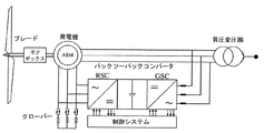
現在、主として風力発電用に使用される可変速度の風力発電機はコンバーターを備えており、系統の事情に応じて、無効電力を供給又は消費する無効電力発生源として利用可能である。二重励磁誘導発電機(Doubly−Fed Induction Generator)はコンバーターを備える。
図1を参照すると、二重励磁誘導発電機(DFIG)は、ローター側のコンバーター(Rotor Side Converter、RSC)及び系統側のコンバーター(Grid Side Converter、GSC)を備える。
Currently, a variable speed wind power generator mainly used for wind power generation includes a converter, and can be used as a reactive power generation source that supplies or consumes reactive power depending on the situation of the system. A double excitation induction generator includes a converter.
Referring to FIG. 1, a double excitation induction generator (DFIG) includes a rotor side converter (Rotor Side Converter, RSC) and a system side converter (Grid Side Converter, GSC).
ローター側のコンバーター(RSC)は、固定子巻線(stator winding)の有効電力及び無効電力を制御し、固定子の有効電力を最大化させるために、最大出力追従制御(maximum power point tracking、MPPT)を行い、固定子ターミナルの電圧を定格電圧に維持し、且つ系統側に無効電力を注入する電圧の制御機能を行う。一方、系統側のコンバーター(GSC)は、DCリンク電圧を一定に維持し、系統事故が発生したときに電圧を修復するために系統側に無効電力を注入する。なお、二重励磁誘導発電機(DFIG)は、系統事故により発生する過電流から二重励磁誘導発電機(DFIG)のコンバーターを保護するために、抵抗を用いて回転子巻線(rotor windings)を短絡させるクローバー(crow bar)をさらに備える。 The rotor-side converter (RSC) controls the active power and reactive power of the stator winding and maximizes the power output tracking control (MPPT) in order to maximize the effective power of the stator. ) To maintain the stator terminal voltage at the rated voltage and perform a voltage control function that injects reactive power into the grid. On the other hand, the system side converter (GSC) maintains the DC link voltage constant, and injects reactive power into the system side in order to restore the voltage when a system fault occurs. In addition, the double excitation induction generator (DFIG) uses a resistor to protect the converter of the double excitation induction generator (DFIG) from an overcurrent caused by a system fault. And a crow bar for short-circuiting.
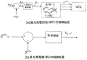
図2は、第1の従来の技術による電圧の制御方法を概略的に示すものである。図2の(a)を参照すると、風力発電団地の制御装置(WPP controller)は、比例積分制御器(PI controller)を用いて、系統連系点(PCC)において測定された電圧upccと連携点基準電圧urefとの間の差分、即ち、電圧誤差(voltage error)Δuを無効電力の補償値Qrefに変換した後、風力発電団地内の各風力発電機WGiに下記の数式2を用いて異なる重み付け値(Pavg/PWGi)を乗算した無効電力設定値QWGi refを算出する。 FIG. 2 schematically shows a voltage control method according to the first prior art. Referring to (a) of FIG. 2, the wind power generation plant control device (WPP controller) uses the proportional integral controller (PI controller) and cooperates with the voltage u pcc measured at the grid connection point (PCC). After the difference between the point reference voltage u ref , that is, the voltage error Δu, is converted into a reactive power compensation value Q ref , the following Equation 2 is used for each wind power generator WGi in the wind power generation complex. Reactive power set value Q WGi ref obtained by multiplying different weight values (P avg / P WGi ).
[数2]
QWGi ref = (Pavg/PWGi)× Qref
[Equation 2]
Q WGi ref = (P avg / P WGi) × Q ref
ここで、iは風力発電団地内の各風力発電機の順番を示し、Pavgは風力発電団地内の全ての風力発電機に対する平均有効電力を示し、PWGiはi番目の風力発電機WGiの有効電力出力を示す。図2の(b)を参照すると、風力発電機の制御装置(WG controller)は、風力発電団地の制御装置から受信される前記無効電力設定値QWGi refに基づいて最終的に無効電流Idr_refを出力する。しかしながら、図2に示す第1の従来の技術による電圧制御方法を活用する場合、系統連系点PCCの電圧upccを基準電圧urefに速やかに修復できるというメリットがあるが、高い重み付け値が乗算される場合に過剰な無効電力が系統側に注入されるが故に大きなオーバーシュート(overshoot)が不可避であるという問題がある。 Here, i indicates the order of each wind power generator in the wind power generation complex, P avg indicates the average active power for all wind power generators in the wind power generation complex, and P WGi indicates the i-th wind power generator WGi. Indicates the active power output. Referring to (b) of FIG. 2, the wind power generator control device (WG controller) finally receives the reactive current I dr_ref based on the reactive power setting value Q WGi ref received from the wind power generation complex control device. Is output. However, when the voltage control method according to the first conventional technique shown in FIG. 2 is utilized, there is an advantage that the voltage u pcc of the grid connection point PCC can be quickly restored to the reference voltage u ref , but a high weighting value is obtained. When multiplying, excessive reactive power is injected into the system side, so that there is a problem that a large overshoot is unavoidable.
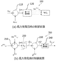
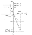
図3は、系統連係要件(grid code)による電圧誤差(Δu)対無効電力の補償値(Qref)の関係の一例を示すものであり、図4は、第2の従来の技術による電圧制御方法を概略的に示すものである。 FIG. 3 shows an example of the relationship between voltage error (Δu) due to grid connection requirement (grid code) and compensation value (Q ref ) of reactive power, and FIG. 4 shows voltage control according to the second conventional technique. The method is schematically shown.
図3を参照すると、系統連系点の基準電圧値urefに対する±5%の電圧誤差の許容範囲を有し、且つ、力率を0.95以上にするという系統連係要件により、電圧誤差Δuが、系統連系点の基準電圧値に比べて、(−0.05pu)≦Δu≦(+0.05pu)の区間において、「約、+0.33puの最大の無効電力」と、「約、−0.33puの最小の無効電力」との間の差分により6.6の大きさの所定の傾きkQの制御スロープ(control slope)が形成されることが確認される。 Referring to FIG. 3, the voltage error Δu has a voltage error tolerance of ± 5% with respect to the reference voltage value u ref at the grid connection point, and the grid linkage requirement that the power factor is 0.95 or more. Compared to the reference voltage value at the grid connection point, in the section of (−0.05 pu) ≦ Δu ≦ (+0.05 pu), “about, +0.33 pu maximum reactive power” and “about, − the control slope of a predetermined gradient k Q difference by the size of 6.6 between the minimum reactive power "on 0.33pu (control slope) are formed is verified.
図4の(a)を参照すると、発電団地制御装置は、系統連系点(PCC)における実際の測定電圧upccと連携点基準電圧urefとの間の差分、即ち、電圧誤差Δuに制御スロープの傾きkQを乗算して無効電力の補償値Qrefを算出する。前記無効電力の補償値Qrefから系統連系点において測定された無効電力値Qpccを差し引いて無効電力の誤差値ΔQPCCを算出し、前記無効電力の誤差値を比例積分して補償基準電圧の誤差値ΔuWGi refを算出する。 Referring to (a) of FIG. 4, the power generation complex control apparatus controls the difference between the actual measurement voltage u pcc at the grid connection point (PCC) and the linkage point reference voltage u ref , that is, the voltage error Δu. A reactive power compensation value Q ref is calculated by multiplying the slope slope k Q. A reactive power error value ΔQ PCC is calculated by subtracting the reactive power value Q pcc measured at the grid connection point from the reactive power compensation value Q ref, and a compensation reference voltage is obtained by proportionally integrating the reactive power error value. An error value Δu WGi ref of is calculated.
図4の(b)を参照すると、各風力発電機の制御装置は、各風力発電機の基準電圧値uWGi ref及び前記補償基準電圧の誤差値ΔuWGi refの和から風力発電機の出力端の電圧値uWGiを差し引いて電圧誤差値を算出し、前記電圧誤差値に変換利得kQiを乗算して無効電流の補償値Idr_refを算出する。前記電圧誤差値から前記無効電流の補償値を算出する過程において乗算される変換利得kQiは、例えば、2であり、他の風力発電機に一律に適用される。 Referring to (b) of FIG. 4, the control device of each wind power generator determines the output terminal of the wind power generator from the sum of the reference voltage value u WGi ref of each wind power generator and the error value Δu WGi ref of the compensation reference voltage. The voltage error value is calculated by subtracting the voltage value u WGi of the current value, and the reactive error compensation value I dr_ref is calculated by multiplying the voltage error value by the conversion gain k Qi . The conversion gain k Qi multiplied in the process of calculating the reactive current compensation value from the voltage error value is, for example, 2, and is uniformly applied to other wind power generators.
しかしながら、上述した第2の従来の技術により系統連系点の電圧を制御する場合、風速などにより経時的に変化する風力発電機ごとの有効電力量は考慮せず、図4に示すように、同じ傾きkQiのみを一律に乗算して無効電流の補償値Idr_refを算出しているので、風力発電機ごとに風速により異なる有効電力とともに変化する可用の無効電力を十分に活用できないという限界があり、その結果、外乱後の定常状態(steady state)で系統連系点の基準電圧uref近くで誤差の発生が不可避であるという問題がある。 However, when the voltage at the grid connection point is controlled by the second conventional technique described above, the active power amount for each wind power generator that changes with time due to the wind speed or the like is not considered, and as shown in FIG. Since the reactive current compensation value I dr_ref is calculated by uniformly multiplying only the same slope k Qi, there is a limit that the available reactive power that varies with the active power that varies depending on the wind speed for each wind power generator cannot be fully utilized. As a result, there is a problem that an error is unavoidable near the reference voltage u ref at the grid connection point in a steady state after disturbance.
本発明は上述した第1、第2の従来の技術の問題を解消するために案出されたものであり、その目的は、系統に外乱が発生して系統連系点(PCC)において測定される電圧の値が予め設定された基準電圧を満たさない場合、これを速やかに修復するように制御するシステム及び方法を提供することにある。 The present invention has been devised to solve the above-described problems of the first and second prior arts, and its purpose is to be measured at a grid connection point (PCC) when a disturbance occurs in the grid. It is an object of the present invention to provide a system and method for performing control so as to quickly repair a voltage value that does not satisfy a preset reference voltage.
本発明が解消しようとする技術的課題は上述した技術的課題に何ら制限されるものではなく、未言及の技術的課題又は他の技術的課題は下記の記載から本発明が属する技術分野において通常の知識を有する者にとって明確に理解できる筈である。 The technical problem to be solved by the present invention is not limited to the technical problem described above, and the technical problem that has not been mentioned or other technical problems is usually described in the technical field to which the present invention belongs from the following description. It should be clear to those who have knowledge of
上述した目的を達成するために、本発明の一側面による、複数の風力発電機を有する風力発電団地の系統連携点電圧の制御方法は、発電団地制御装置の第1の演算部が、連携点基準電圧値(uref)と実際の連携点電圧値(upcc)との間の差分である第1の電圧誤差値を計算するステップと、発電団地制御装置の第1の制御部が、前記第1の電圧誤差値に基づいて補償基準電圧値を算出するステップと、風力発電機の制御装置の第2の演算部が、発電機の基準電圧値及び前記補償基準電圧値の和から風力発電機の出力端の電圧値を差し引いて第2の電圧誤差値を算出するステップと、各風力発電機の制御装置の補償制御部が、前記第2の電圧誤差値に対応する無効電力の補償値を算出するステップと、を含むことを特徴とする。 In order to achieve the above-described object, according to one aspect of the present invention, in the method for controlling the grid linkage point voltage of a wind power generation complex having a plurality of wind power generators, the first calculation unit of the power generation complex control device includes a linkage point. Calculating a first voltage error value that is a difference between the reference voltage value (u ref ) and the actual cooperation point voltage value ( upccc ); and a first control unit of the power generation complex control device, The step of calculating the compensation reference voltage value based on the first voltage error value and the second calculation unit of the control device for the wind power generator generate wind power generation from the sum of the reference voltage value of the generator and the compensation reference voltage value. A step of calculating a second voltage error value by subtracting a voltage value at the output end of the machine, and a compensation control unit of the control device of each wind power generator includes a compensation value of reactive power corresponding to the second voltage error value The step of calculating is included.
また、前記風力発電団地の系統連系点電圧の制御方法は、風力発電機の制御装置の第3の演算部が、前記無効電力の補償値から風力発電機の現在の無効電力値を差し引いて無効電力の誤差値を算出するステップと、風力発電機の制御装置の第2の制御部が、前記無効電力の誤差値に基づいて無効電流の補償値を算出するステップと、風力発電機のコンバーターが、前記無効電流の補償値に対応する無効電流を系統側に注入するステップと、をさらに含む。 Further, in the method of controlling the grid interconnection point voltage of the wind power generation complex, the third calculation unit of the wind power generator control device subtracts the current reactive power value of the wind power generator from the reactive power compensation value. A step of calculating an error value of the reactive power, a step of calculating a compensation value of the reactive current based on the error value of the reactive power by the second control unit of the control device of the wind power generator, and a converter of the wind power generator Injecting a reactive current corresponding to the reactive current compensation value to the grid side.
また、好ましくは、前記無効電流の補償値を算出するステップにおいては、前記無効電力の誤差値を風力発電機の出力端の電圧値で除算する。 Preferably, in the step of calculating the reactive current compensation value, the error value of the reactive power is divided by the voltage value at the output end of the wind power generator.
さらに、好ましくは、前記風力発電機の制御装置は、複数の風力発電機ごとに別設される。 Further, preferably, the control device for the wind power generator is provided separately for each of the plurality of wind power generators.
さらに、好ましくは、前記無効電力の補償値を算出するステップは、前記風力発電機から前記系統側に注入される有効電力の値を測定するステップと、前記風力発電機に対して予め格納された有効電力−無効電力のダイアグラムから、前記測定された有効電力値に対応する可用の無効電力の最大値及び可用の無効電力の最小値を取得するステップと、前記可用の無効電力の最大値及び可用の無効電力の最小値を下記の数式1に代入して変換利得を算出するステップと、前記第2の電圧誤差値に前記変換利得を乗算して前記無効電力の補償値を算出するステップと、を含む。
Further preferably, the step of calculating the compensation value of the reactive power includes a step of measuring a value of active power injected from the wind power generator to the system side, and stored in advance for the wind power generator Obtaining a maximum value of available reactive power and a minimum value of available reactive power corresponding to the measured active power value from an active power-reactive power diagram; and a maximum value and available value of the available reactive power. Substituting the minimum value of the reactive power in
[数1]
kQi = (QWGi max − QWGi min)/w
(式中、kQiは変換利得を示し、QWGi maxは可用の無効電力の最大値を示し、QWGi minは可用の無効電力の最小値を示し、iは各風力発電機の番号を示し、wは第1の電圧誤差値に対して予め設定された許容範囲を示す。)
[Equation 1]
k Qi = (Q WGi max - Q WGi min) / w
( Where k Qi indicates the conversion gain, Q WGi max indicates the maximum value of available reactive power, Q WGi min indicates the minimum value of available reactive power, and i indicates the number of each wind power generator. , W represents an allowable range set in advance for the first voltage error value.)
さらに、好ましくは、前記風力発電機は、二重励磁誘導発電機(DFIG)である。 Further preferably, the wind power generator is a double excitation induction generator (DFIG).
さらに、好ましくは、前記風力発電機は、永久磁石同期発電機である。 Further preferably, the wind power generator is a permanent magnet synchronous generator.
上述した目的を達成するために、本発明の他の側面によれば、連携点基準電圧値(uref)と実際の連携点電圧値(upcc)との間の差分である第1の電圧誤差値を計算し、前記第1の電圧誤差値に基づいて補償基準電圧値を算出する風力発電団地の制御装置と、風力発電機の基準電圧値及び前記補償基準電圧値の和から風力発電機の出力端の電圧値を差し引いて第2の電圧誤差値を算出し、前記第2の電圧誤差値に対応する無効電力の補償値を算出し、前記無効電力の補償値から風力発電機の現在の無効電力値を差し引いて無効電力の誤差値を算出し、前記無効電力の誤差値に基づいて無効電流の補償値を算出する複数の風力発電機の制御装置と、前記無効電流の補償値に対応する無効電流を系統側に注入する複数の風力発電機と、を備え、前記複数の風力発電機の制御装置は、前記複数の風力発電機と一対一で接続されて各風力発電機をそれぞれ別々に制御することを特徴とする風力発電団地の系統連系点電圧の制御システムが提供される。 In order to achieve the above-described object, according to another aspect of the present invention, a first voltage that is a difference between a coordination point reference voltage value (u ref ) and an actual coordination point voltage value (u pcc ). A control device for a wind power generation complex that calculates an error value and calculates a compensation reference voltage value based on the first voltage error value, and a wind generator from a sum of the reference voltage value of the wind generator and the compensation reference voltage value The second voltage error value is calculated by subtracting the voltage value at the output end of the output power, a reactive power compensation value corresponding to the second voltage error value is calculated, and the current value of the wind power generator is calculated from the reactive power compensation value. A reactive power value is subtracted to calculate a reactive power error value, and a reactive current compensation value is calculated based on the reactive power error value. A plurality of wind power generators that inject corresponding reactive currents into the grid, A plurality of wind power generator control devices connected to the plurality of wind power generators in a one-to-one manner, and each wind power generator is controlled separately. A voltage control system is provided.
また、好ましくは、前記各風力発電機の制御装置は、前記系統側に注入される有効電力の値を測定し、予め格納された有効電力−無効電力のダイアグラムから前記測定された有効電力値に対応する可用の無効電力の最大値及び可用の無効電力の最小値を取得し、前記可用の無効電力の最大値及び可用の無効電力の最小値を下記の数式1に代入して変換利得を算出し、前記第2の電圧誤差値に前記変換利得を乗算して前記無効電力の補償値を算出する。
Preferably, the control device of each wind power generator measures a value of active power injected into the grid side, and calculates the active power value from a pre-stored active power-reactive power diagram. The corresponding maximum value of available reactive power and the minimum value of available reactive power are acquired, and the conversion gain is calculated by substituting the maximum value of available reactive power and the minimum value of available reactive power into
[数1]
kQi = (QWGi max − QWGi min)/w
(式中、kQiは変換利得を示し、QWGi maxは可用の無効電力の最大値を示し、QWGi minは可用の無効電力の最小値を示し、iは各風力発電機の番号を示し、wは第1の電圧誤差値に対して予め設定された許容範囲を示す。)
[Equation 1]
k Qi = (Q WGi max - Q WGi min) / w
( Where k Qi indicates the conversion gain, Q WGi max indicates the maximum value of available reactive power, Q WGi min indicates the minimum value of available reactive power, and i indicates the number of each wind power generator. , W represents an allowable range set in advance for the first voltage error value.)
さらに、好ましくは、前記各風力発電機は、風環境に応じて他の風力発電機とは異なる有効電力を系統側に注入し、前記風力発電機の制御装置は、一対一で接続された風力発電機の有効電力値に基づいて、他の風力発電機の制御装置とは異なる無効電力の補償値を算出する。 Further, preferably, each of the wind power generators injects effective power different from that of the other wind power generators into the grid according to a wind environment, and the control device of the wind power generator is connected one-to-one with wind power. Based on the active power value of the generator, a compensation value of reactive power that is different from that of other wind power generator control devices is calculated.
本発明の一実施形態によれば、系統に外乱が発生して系統連系点(PCC)において測定される電圧の値が予め設定された基準電圧を満たさない場合、これを速やかに修復するように制御するシステム及び方法を提供することができる。 According to an embodiment of the present invention, when a disturbance occurs in the grid and the voltage value measured at the grid connection point (PCC) does not satisfy a preset reference voltage, the voltage is quickly repaired. A system and method can be provided.
また、風に応じて変化する有効電力に依存する無効電力の可用最大値及び可用最小値を取得して風力発電機の制御装置の制御スロープの大きさを調節することにより、たとえ風の変動に起因して風力発電団地の運転条件が変化しても、系統連系点(PCC)において測定される電圧を適応的に制御することができる。 Also, by obtaining the maximum and minimum values of reactive power that depend on the active power that changes according to the wind and adjusting the control slope size of the control device of the wind generator, Therefore, even if the operating conditions of the wind power generation complex change, the voltage measured at the grid connection point (PCC) can be controlled adaptively.
さらに、連携点(PCC)において測定された単一の電圧値を用いて風力発電団地内の全ての風力発電機をそれぞれ別々に制御することができる。具体的に、大規模の風力発電団地に配設される風力発電機は、後流効果(wake effect)により異なる有効電力を生産し、その結果、各風力発電機ごとに可用の無効電力も異なってくるが、本発明によれば、風力発電機ごとに異なる無効電力を補償するように制御することができる。 Furthermore, all the wind power generators in the wind power generation complex can be controlled separately using a single voltage value measured at the coordination point (PCC). Specifically, wind power generators installed in large-scale wind power complexes produce different active power due to the wake effect, resulting in different available reactive power for each wind power generator. However, according to the present invention, control can be performed so as to compensate for different reactive power for each wind power generator.
この明細書に開示される実施形態は本発明の範囲を限定するものと解釈又は利用されてはならない。この分野における通常の技術者にとってこの明細書に記載の実施形態をはじめとする説明は様々な応用を有するということはいうまでもない。よって、特許請求の範囲により限定されない限り、任意の実施形態は本発明をより上手に説明するための例示的なものであり、本発明の範囲が実施形態に限定されることを意図しない。なお、本発明を説明するに当たって、関連する公知の構成又は機能についての具体的な説明が本発明の要旨を曖昧にする虞があると認められる場合にはその詳細な説明を省略する。 The embodiments disclosed in this specification should not be construed or utilized to limit the scope of the invention. It goes without saying that explanations including the embodiments described in this specification have various applications for ordinary engineers in this field. Accordingly, unless limited by the claims, any embodiments are exemplary for better explaining the invention and are not intended to limit the scope of the invention to the embodiments. In describing the present invention, when it is recognized that a specific description of a related known configuration or function may obscure the gist of the present invention, a detailed description thereof will be omitted.
以下、添付図面に基づき、本発明の実施形態による風力発電団地の系統連系点電圧の制御システム及び方法についてさらに詳細に説明する。 Hereinafter, a system connection point voltage control system and method for a wind power generation complex according to an embodiment of the present invention will be described in more detail with reference to the accompanying drawings.
図5は、本発明の実施形態による風力発電団地の系統連系点電圧の制御システムを概略的に示す図であり、図6は、本発明の実施形態による各風力発電機の有効電力−無効電力の関係を示すダイアグラムであり、図7は、本発明の実施形態による風力発電機の制御装置が変換利得を算出するための制御スロープを示す図である。 FIG. 5 is a diagram schematically illustrating a system connection point voltage control system of a wind power generation complex according to an embodiment of the present invention, and FIG. 6 is an effective power-invalidity of each wind power generator according to the embodiment of the present invention. FIG. 7 is a diagram illustrating a relationship of electric power, and FIG. 7 is a diagram illustrating a control slope for the wind power generator control device according to the embodiment of the present invention to calculate a conversion gain.
まず、風力発電団地の制御装置100は、第1の演算部110を介して、予め設定された連携点基準電圧値urefと実際の連携点電圧値upccとの間の差分である第1の電圧誤差値Δu1を計算し、第1の制御部120を介して、算出された第1の電圧誤差値Δu1を制御(例えば、比例積分)して補償基準電圧値ΔuWG refを算出するようになっている。
また、風力発電機の制御装置200は、第2の演算部210を介して、発電機の基準電圧値uWGi ref及び補償基準電圧値ΔuWGi refの和から風力発電機の出力端の電圧値uWGiを差し引いて第2の電圧誤差値Δu2を算出し、補償制御部220を介して、第2の電圧誤差値Δu2に対応する無効電力の補償値Qrefを算出する。次に第3の演算部230を介して、算出された無効電力の補償値Qrefから風力発電機の現在の無効電力値QWGiを差し引いて無効電力の誤差値ΔQを算出し、第2の制御部240を介して、前記算出された無効電力の誤差値ΔQに基づいて無効電流の補償値Idr_refを算出するようになっている。
First, the
Further, the wind power
このような風力発電機の制御装置200は、風力発電団地内の全ての風力発電機10と一対一で接続された状態で風力発電団地の制御装置100から引き渡される補償基準電圧値ΔuWG refに基づいて各風力発電機10をそれぞれ別々に制御する。これにより、各風力発電機10は、後流効果により風に応じて異なる有効電力を系統側に注入し、風力発電機の制御装置200は、これと一対一で接続された風力発電機10において生成される有効電力値に基づいて他の風力発電機の制御装置とは異なる無効電力の補償値を算出する。
Such a wind power
具体的に、図5の(a)を参照すると、風力発電団地の制御装置100は、第1の演算部110及び第1の制御部120を備える。第1の演算部110は、系統連系点(PCC)に対して予め設定された連携点基準電圧値urefと実際の連携点電圧値upccとの間の差分を計算して第1の電圧誤差値Δu1を算出するようになっている。
Specifically, referring to (a) of FIG. 5, the
第1の制御部120は、第1の演算部110から転送される第1の電圧誤差値Δu1に対する積分、比例積分又は比例積分微分の制御を行って補償基準電圧値ΔuWG refを算出する。このような補償基準電圧値ΔuWG refは、系統連系点(PCC)の電圧の変動を抑えるのに必要な無効電力の補償値Qrefを算出するために風力発電団地内の全ての風力発電機に対して同様に提供される。
The
次いで、図5の(b)を参照すると、各風力発電機の制御装置200は、第2の演算部210と、補償制御部220と、第3の演算部230及び第2の制御部240を備える。一方、本発明の実施形態による風力発電機の制御装置200は風力発電機10に組み込まれてもよいが、場合によっては、別途に外付けされた状態で有線又は無線ネットワークを介して風力発電機と接続されて運営されるものと理解されるべきである。
Next, referring to FIG. 5B, the
第2の演算部210は、各風力発電機の基準電圧値uWGi ref及び補償基準電圧値ΔuWG refの和uWGi ref+ΔuWG refから該風力発電機の出力端の電圧値uWGiを差し引いて第2の電圧誤差値Δu2を算出する。ここで、風力発電機の基準電圧値uWGi refとは、各風力発電機の出力端に対して予め設定された基準電圧値のことをいい、風力発電機の出力端の電圧値uWGiとは、各風力発電機出力端において測定された電圧値のことをいい、各パラメータ名内の「i」とは、風力発電機の順番のことをいう。
The
一方、図6を参照すると、各風力発電機10において生成される有効電力に対して可用の無効電力の範囲を取得するために別途格納された有効電力対無効電力のダイアグラムデータが確認できる。具体例を挙げると、補償制御部220は、特定の時点において測定される第1の風力発電機WG1の有効電力出力PWG1を前記有効電力対無効電力のダイアグラムに適用して可用の無効電力の最大値QWG1 max及び最小値QWG1 minを取得し、同様にして第2の風力発電機WG2の有効電力の出力PWG2に対する可用の無効電力の最大値QWG2 max及び最小値QWG2 minを取得する。この場合、例えば、図6に示すように、第1の風力発電機WG1に対する可用の無効電力の最大値QWG1 max及び最小値QWG1 minがそれぞれ0.55pu及び−0.93puとして取得され、第2の風力発電機WG2に対する可用の無効電力の最大値QWG2 max及び最小値QWG2 minがそれぞれ0.47pu及び−0.84puとして取得される。補償制御部220は、取得された最大値及び最小値を下記の数式1に適用して変換利得kQiを算出する。
On the other hand, referring to FIG. 6, active power versus reactive power diagram data separately stored in order to obtain a range of available reactive power for the active power generated in each
[数1]
kQi = (QWGi max − QWGi min)/w
ここで、数式1の「i」は各風力発電機の順番を示し、kQiは変換利得を示し、QWGi maxは可用の無効電力の最大値を示し、QWGi minは可用の無効電力の最小値を示し、wは第1の電圧誤差値Δu1に対して予め設定された許容範囲を示す。
[Equation 1]
k Qi = (Q WGi max - Q WGi min) / w
Here, “i” in
例えば、系統連係要件に系統連系点(PCC)に対する電圧誤差の許容範囲が基準電圧値urefに比べて(−0.05pu)〜(+0.05pu)であることを提示する場合に、前記wは0.1puに設定されて第1の変換利得kQ1は14.8として算出され、第2の変換利得kQ2は13.1として算出される。 For example, when presenting that the allowable range of the voltage error with respect to the grid connection point (PCC) is (−0.05 pu) to (+0.05 pu) compared to the reference voltage value u ref in the grid linkage requirement, w is set to 0.1 pu, the first conversion gain k Q1 is calculated as 14.8, and the second conversion gain k Q2 is calculated as 13.1.
補償制御部220は、各風力発電機10における第2の電圧誤差値Δu2に上述した演算制御により取得した変換利得kQiを乗算して無効電力の補償値Qrefを算出する。
The
このような第1の変換利得kQ1及び第2の変換利得kQ2の大きさは何れも、図4を参照して上述した第1、第2の従来の技術における傾きkQである6.6よりも大きな値であることが確認でき、その結果、本発明の実施形態が従来の技術に比べて一層速やかに系統連系点(PCC)の電圧の変動を抑制できる。 The magnitudes of the first conversion gain k Q1 and the second conversion gain k Q2 are both the slope k Q in the first and second conventional techniques described above with reference to FIG. It can be confirmed that the value is larger than 6, and as a result, the embodiment of the present invention can suppress the fluctuation of the voltage at the grid connection point (PCC) more quickly than the conventional technique.
第3の演算部230は、補償制御部220により算出された無効電力の補償値Qrefから風力発電機の現在の無効電力値QWGiを差し引いて無効電力の誤差値ΔQを算出する。また、第2の制御部240は、第3の演算部230により算出された無効電力の誤差値ΔQに対する積分、比例積分又は比例積分微分の制御を行って無効電流の補償値Idr_refを算出する。
The
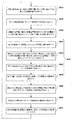
図8は、本発明の実施形態による風力発電団地の系統連系点電圧の制御方法の各ステップを順次に示すフローチャートである。 FIG. 8 is a flowchart sequentially illustrating the steps of the method of controlling the grid interconnection point voltage of the wind power generation complex according to the embodiment of the present invention.
図8を参照すると、本発明の実施形態による制御方法は、まず、風力発電団地の制御装置100の第1の演算部110が、連携点基準電圧値urefと実際の連携点電圧値upccとの間の差分である第1の電圧誤差値Δu1を計算する(ステップS510)。
Referring to FIG. 8, in the control method according to the embodiment of the present invention, first, the
次いで、風力発電団地の制御装置100の第1の制御部120が、第1の電圧誤差値Δu1に対する積分、比例積分、比例積分微分の制御を行って補償基準電圧値ΔuWG refを算出する(ステップS520)。このような補償基準電圧値ΔuWG refは、風力発電団地内の全ての風力発電機に対して共通して提供される。
Next, the
次いで、第i番目の風力発電機の制御装置200の第2の演算部210が、発電機の基準電圧値uWGi ref及び補償基準電圧値ΔuWG refの和uWGi ref+ΔuWG refから風力発電機の出力端の電圧値uWGiを差し引いて第2の電圧誤差値Δu2を算出する(ステップS530)。
Next, the
次いで、風力発電機の制御装置200の補償制御部220が、第2の電圧誤差値Δu2に対応する無効電力の補償値Qrefを算出する(ステップS540)。このとき、無効電力の補償値Qrefを算出するステップS540は、具体的に、風力発電機から系統側に注入される有効電力値を測定(ステップS541)した後、風力発電機に対して別途格納された有効電力対無効電力のダイアグラム(図6参照)から前記測定された有効電力値に対応する可用の無効電力の最大値QWGi max及び可用の無効電力の最小値QWGi maxを取得し(ステップS542)、次いで、可用の無効電力の最大値QWGi max及び可用の無効電力の最小値QWGi maxを上述した数式1に代入して変換利得kQiを算出(ステップS543)した後、第2の電圧誤差値Δu2に変換利得kQiを乗算して無効電力の補償値Qrefを算出(ステップS544)する過程を含む。
Next, the
次いで、風力発電機の制御装置200の第3の演算部230が、無効電力の補償値Qrefから風力発電機の現在の無効電力値QWGiを差し引いて無効電力の誤差値ΔQを算出する(ステップS550)。
Next, the
次いで、風力発電機の制御装置200の第2の制御部240が、無効電力の誤差値ΔQに対する積分、比例積分又は比例積分微分の制御を行って無効電流の補償値Idr_refを算出する(ステップS560)。又は、第2の制御部240が、無効電力の誤差値ΔQを風力発電機の出力端の電圧値uWGiで除算して無効電流の補償値Idr_refを算出する。
Next, the
無効電流の補償値を算出するステップ(ステップS560)が終わると、風力発電機のコンバーターが無効電流の補償値Idrefに対応する無効電流を系統側に注入する過程が続く(ステップS570)。 When the step of calculating the reactive current compensation value (step S560) is completed, the converter of the wind power generator continues the process of injecting the reactive current corresponding to the reactive current compensation value Idref to the system side (step S570).
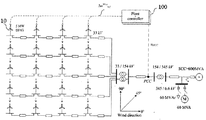
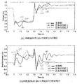
図9は、本発明の実施形態をシミュレーションするための風力発電団地及び系統を備えるシステムの模型を示す模式図であり、図10は、図9によるシミュレーション結果を示すグラフである。 FIG. 9 is a schematic diagram illustrating a model of a system including a wind power generation complex and a system for simulating the embodiment of the present invention, and FIG. 10 is a graph illustrating a simulation result according to FIG.
まず、図9を参照すると、風力発電団地は、合計20台の5MW級の二重励磁誘導発電機(DFIG)により構成されている。二重励磁誘導発電機(DFIG)は4台ずつ一本の給電線に接続され、5本の給電線は33kV/154kV変電所の変圧器と接続され、この変圧器は、10kmの長さを有する154kV用の海底ケーブルを介して系統連系点(PCC)と接続されるシミュレーション模擬システムのモデルであることを確認することができる。なお、隣り合う2台の二重励磁誘導発電機(DFIG)間の距離は1kmに設定され、系統の短絡比は6に設定される。 First, referring to FIG. 9, the wind power generation complex is composed of a total of 20 5 MW class double excitation induction generators (DFIGs). Four double excitation induction generators (DFIG) are connected to one power supply line, and five power supply lines are connected to a transformer of a 33 kV / 154 kV substation, and this transformer has a length of 10 km. It can be confirmed that it is a model of a simulation simulation system that is connected to a grid connection point (PCC) through a submarine cable for 154 kV. The distance between two adjacent double excitation induction generators (DFIGs) is set to 1 km, and the short circuit ratio of the system is set to 6.
図10は、図9に示すシミュレーションモデルに対して7秒の時点から0.3秒間系統に3相短絡事故を模擬して系統連系点電圧upccの修復性能をテストした結果を示すグラフである。風力発電団地の制御装置100から風力発電機の制御装置200へと転送される補償基準電圧値ΔuWG refは、所定の周期(例えば、0.1秒当たりに1回)を有する。このとき、電圧の制御に際して後流効果を反映するために風力発電団地に吹いてくる風の風速及び風向は、それぞれ秒速12m及び0°(deg)に設定されている。
FIG. 10 is a graph showing a result of testing the restoration performance of the grid connection point voltage upcc by simulating a three-phase short circuit accident in the system for 0.3 seconds from the time point of 7 seconds with respect to the simulation model shown in FIG. is there. The compensation reference voltage value Δu WG ref transferred from the
図10を参照すると、赤色の実線(イ)は本発明の実施形態による制御方法に対するシミュレーション結果を示すものであり、青色の実線(ロ)は第1の従来の技術に対するシミュレーション結果を示すものであり(図2参照)、緑色の実線(ハ)は第2の従来の技術に対するシミュレーション結果を示すもの(図4参照)である。 Referring to FIG. 10, a red solid line (A) indicates a simulation result for the control method according to the embodiment of the present invention, and a blue solid line (B) indicates a simulation result for the first conventional technique. Yes (see FIG. 2), the green solid line (c) shows the simulation results for the second prior art (see FIG. 4).
図10の(a)を参照すると、3種類の制御方法の何れの場合でも、系統3相短絡事故が模擬的に発生した7秒時点の直後に系統連系点(PCC)において測定された連携点電圧値upccが約0.45puまで降下したことが確認できる。また、図10の(b)を参照すると、7秒時点の直後に、本発明の実施形態及び第2の従来の技術による制御方法が第1の従来の技術による制御方法に比べてより多くの無効電力が系統側に提供されていることが確認できる。このような結果は、風力発電機が、本発明及び第2の従来の技術では電圧制御モードを利用するのに対して、第1の従来の技術では無効電力制御モードを利用することに起因する。 Referring to (a) of FIG. 10, in any of the three types of control methods, the link measured at the grid connection point (PCC) immediately after 7 seconds when the grid 3-phase short-circuit accident occurred in a simulated manner. It can be confirmed that the point voltage value u pcc has dropped to about 0.45 pu. Further, referring to FIG. 10B, immediately after the 7 second time point, the control method according to the embodiment of the present invention and the second prior art is more than the control method according to the first prior art. It can be confirmed that reactive power is provided to the grid side. Such a result is due to the fact that the wind power generator uses the voltage control mode in the present invention and the second conventional technique, whereas the first conventional technique uses the reactive power control mode. .
一方、7.3秒後の結果について、図10の(a)を参照すると、第1の従来の技術は、本発明及び第2の従来の技術に比べて、連携点電圧値upccが連携点基準電圧値urefまで修復されるのにより長い時間がかかることが確認できるが、これは、有効電力値に依存する重み付け値(図2参照)が過剰に大きな値を有するためである。即ち、本発明の実施形態及び第2の従来の技術による方が第1の従来の技術による方に比べてより速やかに連携点電圧値upccが連携点基準電圧値urefに修復されることが確認できる。 On the other hand, referring to (a) of FIG. 10 for the result after 7.3 seconds, the first conventional technique has a higher coordination point voltage value upcc than the present invention and the second conventional technique. It can be confirmed that it takes a longer time to be restored to the point reference voltage value u ref because the weighting value (see FIG. 2) depending on the active power value has an excessively large value. That is, the cooperation point voltage value u pcc is restored to the cooperation point reference voltage value u ref more quickly in the embodiment of the present invention and the second conventional technique than in the first conventional technique. Can be confirmed.
上述した「備える」「含む」などの用語は、特に断りのない限り、単に当該構成要素が組み込まれることを意味するものであって、他の構成要素が組み込まれることを排除するわけではなく、他の構成要素がさらに組み込まれ得るものと解釈されなければならない。 Unless otherwise specified, the terms such as “comprising” and “including” merely mean that the component is incorporated, and do not exclude the incorporation of other components. It should be construed that other components can be further incorporated.
上述した本発明の実施形態は単に例示のために開示されるものであり、これらによって本発明が限定されない。また、本発明に対する技術分野において通常の知識を有する者であれば、本発明の思想及び範囲内において様々に修正及び変更できる筈であり、このような修正及び変更は本発明の範囲に属するものと理解されるべきである。 The embodiments of the present invention described above are disclosed by way of example only and are not intended to limit the present invention. Any person who has ordinary knowledge in the technical field of the present invention can make various modifications and changes within the spirit and scope of the present invention, and such modifications and changes belong to the scope of the present invention. Should be understood.
10 風力発電機
100 風力発電団地の制御装置
110 第1の演算部
120 第1の制御部
200 風力発電機の制御装置
210 第2の演算部
220 補償制御部
230 第3の演算部
240 第2の制御部
DESCRIPTION OF
Claims (9)
発電団地制御装置の第1の演算部が、連携点基準電圧値(uref)と実際の連携点電圧値(upcc)との間の差分である第1の電圧誤差値を計算するステップと、
発電団地制御装置の第1の制御部が、前記第1の電圧誤差値に基づいて補償基準電圧値を算出するステップと、
風力発電機の制御装置の第2の演算部が、発電機の基準電圧値及び前記補償基準電圧値の和から風力発電機の出力端の電圧値を差し引いて第2の電圧誤差値を算出するステップと、
風力発電機の制御装置の補償制御部が、前記第2の電圧誤差値に対応する無効電力の補償値を算出するステップと、
風力発電機の制御装置の第3の演算部が、前記無効電力の補償値から風力発電機の現在の無効電力値を差し引いて無効電力の誤差値を算出するステップと、
風力発電機の制御装置の第2の制御部が、前記無効電力の誤差値に基づいて無効電流の補償値を算出するステップと、
風力発電機のコンバーターが、前記無効電流の補償値に対応する無効電流を系統側に注入するステップと、
を含むことを特徴とする風力発電団地の系統連系点電圧の制御方法。 In a method for controlling a grid linkage point voltage of a wind power generation complex having a plurality of wind power generators,
A step of calculating a first voltage error value, which is a difference between the cooperation point reference voltage value (u ref ) and the actual cooperation point voltage value (u pcc ), by the first calculation unit of the power generation complex control device; ,
A first control unit of the power generation complex control device calculating a compensation reference voltage value based on the first voltage error value;
The second calculation unit of the control device for the wind power generator calculates a second voltage error value by subtracting the voltage value at the output end of the wind power generator from the sum of the reference voltage value of the generator and the compensation reference voltage value. Steps,
A step of calculating a compensation value of reactive power corresponding to the second voltage error value by a compensation control unit of the control device of the wind power generator;
A step of calculating a reactive power error value by subtracting a current reactive power value of the wind power generator from a compensation value of the reactive power, a third calculation unit of the control device of the wind power generator;
A step of calculating a reactive current compensation value based on an error value of the reactive power by a second control unit of the wind turbine generator;
A step of injecting a reactive current corresponding to the reactive current compensation value into the grid side by a converter of the wind power generator;
A method for controlling a grid interconnection point voltage of a wind power generation complex, comprising:
前記無効電力の誤差値を風力発電機の出力端の電圧値で除算することを特徴とする請求項1に記載の風力発電団地の系統連系点電圧の制御方法。 In the step of calculating the compensation value of the reactive current,
The method of controlling a grid interconnection point voltage of a wind power generation complex according to claim 1, wherein the error value of the reactive power is divided by a voltage value of an output terminal of the wind power generator.
複数の風力発電機ごとに別設されることを特徴とする請求項1に記載の風力発電団地の系統連系点電圧の制御方法。 The wind power generator control device is:
The method for controlling the grid interconnection point voltage of the wind power generation complex according to claim 1, wherein the method is provided separately for each of the plurality of wind power generators.
前記風力発電機から前記系統側に注入される有効電力の値を測定するステップと、
前記風力発電機に対して予め格納された有効電力−無効電力のダイアグラムから、前記測定された有効電力値に対応する可用の無効電力の最大値及び可用の無効電力の最小値を取得するステップと、
前記可用の無効電力の最大値及び可用の無効電力の最小値を下記の数式1に代入して変換利得を算出するステップと、
前記第2の電圧誤差値に前記変換利得を乗算して前記無効電力の補償値を算出するステップと、
を含むことを特徴とする請求項1に記載の風力発電団地の系統連系点電圧の制御方法。
[数1]
kQi = (QWGi max − QWGi min)/w
(式中、kQiは変換利得を示し、QWGi maxは可用の無効電力の最大値を示し、QWGi minは可用の無効電力の最小値を示し、iは各風力発電機の番号を示し、wは第1の電圧誤差値に対して予め設定された許容範囲を示す。) Calculating the reactive power compensation value,
Measuring a value of active power injected from the wind power generator to the grid side;
Obtaining a maximum value of available reactive power and a minimum value of available reactive power corresponding to the measured active power value from an active power-reactive power diagram stored in advance for the wind power generator; ,
Substituting the maximum value of the available reactive power and the minimum value of the available reactive power into Equation 1 below to calculate a conversion gain;
Multiplying the second voltage error value by the conversion gain to calculate a compensation value of the reactive power;
The control method of the grid connection point voltage of the wind power generation complex of Claim 1 characterized by the above-mentioned.
[Equation 1]
k Qi = (Q WGi max - Q WGi min) / w
( Where k Qi indicates the conversion gain, Q WGi max indicates the maximum value of available reactive power, Q WGi min indicates the minimum value of available reactive power, and i indicates the number of each wind power generator. , W represents an allowable range set in advance for the first voltage error value.)
二重励磁誘導発電機(DFIG)であることを特徴とする請求項1に記載の風力発電団地の系統連系点電圧の制御方法。 The wind power generator
It is a double excitation induction generator (DFIG), The control method of the grid connection point voltage of the wind power generation complex of Claim 1 characterized by the above-mentioned.
永久磁石同期発電機であることを特徴とする請求項1に記載の風力発電団地の系統連系点電圧の制御方法。 The wind power generator
It is a permanent magnet synchronous generator, The control method of the grid connection point voltage of the wind power generation complex of Claim 1 characterized by the above-mentioned.
風力発電機の基準電圧値及び前記補償基準電圧値の和から風力発電機の出力端の電圧値を差し引いて第2の電圧誤差値を算出し、前記第2の電圧誤差値に対応する無効電力の補償値を算出し、前記無効電力の補償値から風力発電機の現在の無効電力値を差し引いて無効電力の誤差値を算出し、前記無効電力の誤差値に基づいて無効電流の補償値を算出する複数の風力発電機の制御装置と、
前記無効電流の補償値に対応する無効電流を系統側に注入する複数の風力発電機と、
を備え、
前記複数の風力発電機の制御装置は、前記複数の風力発電機と一対一で接続されて各風力発電機をそれぞれ別々に制御することを特徴とする風力発電団地の系統連系点電圧の制御システム。 A first voltage error value, which is a difference between the cooperation point reference voltage value (u ref ) and the actual cooperation point voltage value (u pcc ), is calculated, and a compensation reference voltage is calculated based on the first voltage error value. A wind power plant control device for calculating the value;
A second voltage error value is calculated by subtracting the voltage value at the output end of the wind power generator from the sum of the reference voltage value of the wind power generator and the compensation reference voltage value, and the reactive power corresponding to the second voltage error value The reactive power error value is calculated by subtracting the current reactive power value of the wind power generator from the reactive power compensation value, and the reactive current compensation value is calculated based on the reactive power error value. A plurality of wind power generator controllers to be calculated;
A plurality of wind power generators that inject reactive current corresponding to the compensation value of the reactive current to the grid side;
With
The control device for the plurality of wind power generators is connected to the plurality of wind power generators in a one-to-one manner, and controls each wind power generator separately. system.
前記系統側に注入される有効電力の値を測定し、予め格納された有効電力−無効電力のダイアグラムから前記測定された有効電力値に対応する可用の無効電力の最大値及び可用の無効電力の最小値を取得し、前記可用の無効電力の最大値及び可用の無効電力の最小値を下記の数式1に代入して変換利得を算出し、前記第2の電圧誤差値に前記変換利得を乗算して前記無効電力の補償値を算出することを特徴とする請求項7に記載の風力発電団地の系統連系点電圧の制御システム。
[数1]
kQi = (QWGi max − QWGi min)/w
(式中、kQiは変換利得を示し、QWGi maxは可用の無効電力の最大値を示し、QWGi minは可用の無効電力の最小値を示し、iは各風力発電機の番号を示し、wは第1の電圧誤差値に対して予め設定された許容範囲を示す。) The control device for each wind power generator is:
The value of the active power injected into the system side is measured, and the maximum value of the available reactive power and the available reactive power corresponding to the measured active power value from the previously stored active power-reactive power diagram are measured. The minimum value is obtained, the conversion gain is calculated by substituting the maximum value of the available reactive power and the minimum value of the available reactive power into the following Equation 1, and the second voltage error value is multiplied by the conversion gain. The compensation value of the reactive power is calculated, and the grid interconnection point voltage control system of the wind power generation complex according to claim 7.
[Equation 1]
k Qi = (Q WGi max - Q WGi min) / w
( Where k Qi indicates the conversion gain, Q WGi max indicates the maximum value of available reactive power, Q WGi min indicates the minimum value of available reactive power, and i indicates the number of each wind power generator. , W represents an allowable range set in advance for the first voltage error value.)
前記風力発電機の制御装置は、一対一で接続された風力発電機の有効電力値に基づいて、他の風力発電機の制御装置とは異なる無効電力の補償値を算出することを特徴とする請求項8に記載の風力発電団地の系統連系点電圧の制御システム。
Each of the wind power generators injects active power different from that of other wind power generators according to the wind environment to the grid side,
The wind power generator control device calculates a reactive power compensation value different from other wind power generator control devices based on the active power value of the wind power generator connected in a one-to-one relationship. The control system of the grid connection point voltage of the wind power generation complex of Claim 8.
Applications Claiming Priority (2)
| Application Number | Priority Date | Filing Date | Title |
|---|---|---|---|
| KR10-2014-0061454 | 2014-05-22 | ||
| KR1020140061454A KR101423212B1 (en) | 2014-05-22 | 2014-05-22 | Voltage control system and method at the point of common coupling of wind power plant |
Publications (2)
| Publication Number | Publication Date |
|---|---|
| JP5719081B1 true JP5719081B1 (en) | 2015-05-13 |
| JP2015223068A JP2015223068A (en) | 2015-12-10 |
Family
ID=51743010
Family Applications (1)
| Application Number | Title | Priority Date | Filing Date |
|---|---|---|---|
| JP2014257483A Expired - Fee Related JP5719081B1 (en) | 2014-05-22 | 2014-12-19 | System and method for controlling grid interconnection voltage of wind power generation complex |
Country Status (3)
| Country | Link |
|---|---|
| US (1) | US9217419B2 (en) |
| JP (1) | JP5719081B1 (en) |
| KR (1) | KR101423212B1 (en) |
Cited By (2)
| Publication number | Priority date | Publication date | Assignee | Title |
|---|---|---|---|---|
| CN105529720A (en) * | 2015-11-23 | 2016-04-27 | 国家电网公司 | Dynamic reactive power priority based automatic switching method of capacitor of wind power plant |
| CN105529719A (en) * | 2015-11-23 | 2016-04-27 | 国家电网公司 | Adjusting method based on comprehensive considering of voltage and reactive power for SVG (Static Var generator) of wind power plant |
Families Citing this family (33)
| Publication number | Priority date | Publication date | Assignee | Title |
|---|---|---|---|---|
| CN104300547B (en) * | 2014-10-26 | 2016-06-08 | 国家电网公司 | The idle method of replacing of wind energy turbine set dynamic reactive compensation device and blower fan |
| KR102190475B1 (en) * | 2015-06-29 | 2020-12-14 | 두산중공업 주식회사 | Apparatus and Method for controlling real maximum power of wind farm considering wake effect |
| US10148089B2 (en) * | 2015-09-14 | 2018-12-04 | Mitsubishi Electric Research Laboratories, Inc. | Automatic power generation control in micro-grids |
| US9997921B2 (en) * | 2015-10-07 | 2018-06-12 | General Electric Company | Solar power conversion system and method |
| CN105529740B (en) * | 2016-01-28 | 2018-06-29 | 云南电网有限责任公司电力科学研究院 | A kind of wind power plant and the flickering appraisal procedure and system at wind farm grid-connected place |
| DK3200303T3 (en) * | 2016-01-29 | 2024-04-29 | Siemens Gamesa Renewable Energy As | OPERATION OF A WINDMILL IN A WINDMILL PARK |
| CN105811400A (en) * | 2016-03-18 | 2016-07-27 | 国网上海市电力公司 | Self-adaptive control method for modes of low-voltage microgrid |
| US9970417B2 (en) * | 2016-04-14 | 2018-05-15 | General Electric Company | Wind converter control for weak grid |
| CN109416019B (en) * | 2016-07-06 | 2020-05-05 | 维斯塔斯风力系统集团公司 | Wind power plant with multiple wind turbine generators and a power plant controller |
| CN106130068B (en) * | 2016-07-19 | 2018-06-26 | 东北大学 | A kind of wind power plant cluster reactive voltage control system and method based on Reactive Power Margin |
| EP3501080B1 (en) * | 2016-09-16 | 2020-04-29 | Vestas Wind Systems A/S | Reactive power production of wind turbine generators within wind wake zone |
| US10439533B2 (en) * | 2017-01-05 | 2019-10-08 | General Electric Company | Power converter for doubly fed induction generator wind turbine systems |
| CN108808725B (en) * | 2017-05-05 | 2023-03-21 | 通用电气公司 | System and method for reactive power control of wind farm |
| US11264802B2 (en) | 2017-08-15 | 2022-03-01 | Vestas Wind Systems A/S | Relating to reactive power control in wind power plants |
| EP3682518A4 (en) * | 2017-09-15 | 2021-01-13 | General Electric Company | Systems and methods for controlling electrical power systems connected to power grid |
| FR3071620B1 (en) * | 2017-09-26 | 2020-10-02 | Ge Energy Power Conversion Technology Ltd | DEVICE AND METHOD FOR TESTING POWER MODULES |
| CN107944142B (en) * | 2017-11-24 | 2019-12-03 | 国电联合动力技术有限公司 | High voltage crossing ability Simulation Evaluation model and Simulation Evaluation method based on it |
| CN109962492B (en) * | 2017-12-25 | 2021-03-26 | 北京金风科创风电设备有限公司 | Power compensation method and device for converter of wind generating set and converter |
| CN110080944B (en) * | 2018-01-26 | 2021-09-24 | 通用电气公司 | Wind power generation system and control method thereof |
| FR3080457B1 (en) * | 2018-04-20 | 2020-10-23 | Sagemcom Energy & Telecom Sas | ELECTRICAL ENERGY METER CONTAINING A CURRENT MEASURING CIRCUIT AND A VOLTAGE MEASURING CIRCUIT |
| KR102568403B1 (en) * | 2018-10-30 | 2023-08-21 | 한국전기연구원 | Methdo and system for controlling distribution network including numerous distributed energy resource |
| CN109818802A (en) * | 2019-02-25 | 2019-05-28 | 四川师范大学 | Secondary equipment of intelligent converting station analogue system |
| CN109755964B (en) * | 2019-03-18 | 2022-06-07 | 哈尔滨工业大学 | Control method for improving stability of double-fed wind turbine generator under weak grid condition |
| CN111064179B (en) * | 2019-10-22 | 2021-04-27 | 国网山东省电力公司电力科学研究院 | Comprehensive control method and system for ensuring voltage safety in power recovery stage of multi-feed-in direct current system |
| CN110932287B (en) * | 2019-11-14 | 2023-03-24 | 国网新疆电力有限公司 | Power grid voltage control method for reducing near-zone voltage fluctuation of extra-high voltage direct current converter station |
| KR102238494B1 (en) * | 2020-01-15 | 2021-04-09 | 영남대학교 산학협력단 | Sensorless control System of DFIG |
| US11791655B2 (en) | 2020-04-02 | 2023-10-17 | Dominion Energy, Inc. | Electrical grid control systems and methods using dynamically mapped effective impedance |
| WO2021223829A1 (en) * | 2020-05-06 | 2021-11-11 | Vestas Wind Systems A/S | Method and control systems for voltage control in renewable energy power plant |
| CN112310971B (en) * | 2020-09-01 | 2021-08-24 | 新疆金风科技股份有限公司 | Semi-direct-drive direct-current wind generating set and control method and equipment thereof |
| CN113595093B (en) * | 2021-07-19 | 2022-07-22 | 南方电网科学研究院有限责任公司 | Reactive voltage automatic control method and device for new energy power station and storage medium |
| US11870251B2 (en) * | 2021-08-04 | 2024-01-09 | General Electric Company | System and method for controlling a power generating system |
| CN114221354B (en) * | 2021-12-27 | 2024-07-02 | 上海电气风电集团股份有限公司 | Power control method and system for wind farm and readable storage medium |
| CN116148519B (en) * | 2023-01-06 | 2024-01-26 | 华能广东汕头海上风电有限责任公司 | Marine wind farm voltage monitoring and early warning method and system |
Citations (4)
| Publication number | Priority date | Publication date | Assignee | Title |
|---|---|---|---|---|
| JPH02159930A (en) * | 1988-12-09 | 1990-06-20 | Toshiba Corp | Reactive power controller |
| JP2012044863A (en) * | 2006-02-28 | 2012-03-01 | Hitachi Ltd | Wind power generator |
| JP2012200111A (en) * | 2011-03-23 | 2012-10-18 | Kansai Electric Power Co Inc:The | Voltage rise suppression device and dispersed power supply interconnection system |
| WO2013179470A1 (en) * | 2012-05-31 | 2013-12-05 | 三菱重工業株式会社 | Voltage control device, control method thereof and voltage control program |
Family Cites Families (14)
| Publication number | Priority date | Publication date | Assignee | Title |
|---|---|---|---|---|
| US4251735A (en) * | 1979-07-23 | 1981-02-17 | United Technologies Corporation | Dual speed control circuit for power flow through an inverter |
| US5798633A (en) * | 1996-07-26 | 1998-08-25 | General Electric Company | Battery energy storage power conditioning system |
| JP3755075B2 (en) * | 1999-01-22 | 2006-03-15 | 株式会社日立製作所 | Power fluctuation compensation device |
| AU2001274396A1 (en) * | 2000-05-23 | 2001-12-03 | Vestas Wind Systems A/S | Variable speed wind turbine having a matrix converter |
| US6586914B2 (en) * | 2001-11-19 | 2003-07-01 | General Electric Company | Wound field synchronous machine control system and method |
| JP5278414B2 (en) * | 2004-10-29 | 2013-09-04 | 東京電力株式会社 | Distributed power supply, distribution facility, and power supply method |
| US7511385B2 (en) * | 2005-11-11 | 2009-03-31 | Converteam Ltd | Power converters |
| ES2378349T3 (en) * | 2007-05-31 | 2012-04-11 | Vestas Wind Systems A/S | Wind turbine with resonant control system |
| WO2009083447A2 (en) * | 2007-12-28 | 2009-07-09 | Vestas Wind Systems A/S | Apparatus and method for operating a wind turbine under low utility grid voltage conditions |
| JP4749433B2 (en) * | 2008-01-22 | 2011-08-17 | 株式会社日立製作所 | Distributed power supply system and control method thereof |
| KR100985921B1 (en) | 2008-04-23 | 2010-10-11 | 명지대학교 산학협력단 | wind power system using doubly fed induction generator and control method thereof |
| KR101294929B1 (en) | 2011-12-14 | 2013-08-08 | 군산대학교산학협력단 | Wind Power Generation System and Control Method Thereof |
| KR101354513B1 (en) | 2011-12-14 | 2014-02-04 | 주식회사 케이렘 | Wind Power Gernator and Contril Method for the same |
| KR101297082B1 (en) | 2011-12-30 | 2013-08-19 | 한국전기연구원 | Integrated power control device and control method for wind power plant control system |
-
2014
- 2014-05-22 KR KR1020140061454A patent/KR101423212B1/en active IP Right Grant
- 2014-12-19 JP JP2014257483A patent/JP5719081B1/en not_active Expired - Fee Related
-
2015
- 2015-01-06 US US14/590,208 patent/US9217419B2/en not_active Expired - Fee Related
Patent Citations (4)
| Publication number | Priority date | Publication date | Assignee | Title |
|---|---|---|---|---|
| JPH02159930A (en) * | 1988-12-09 | 1990-06-20 | Toshiba Corp | Reactive power controller |
| JP2012044863A (en) * | 2006-02-28 | 2012-03-01 | Hitachi Ltd | Wind power generator |
| JP2012200111A (en) * | 2011-03-23 | 2012-10-18 | Kansai Electric Power Co Inc:The | Voltage rise suppression device and dispersed power supply interconnection system |
| WO2013179470A1 (en) * | 2012-05-31 | 2013-12-05 | 三菱重工業株式会社 | Voltage control device, control method thereof and voltage control program |
Cited By (4)
| Publication number | Priority date | Publication date | Assignee | Title |
|---|---|---|---|---|
| CN105529720A (en) * | 2015-11-23 | 2016-04-27 | 国家电网公司 | Dynamic reactive power priority based automatic switching method of capacitor of wind power plant |
| CN105529719A (en) * | 2015-11-23 | 2016-04-27 | 国家电网公司 | Adjusting method based on comprehensive considering of voltage and reactive power for SVG (Static Var generator) of wind power plant |
| CN105529719B (en) * | 2015-11-23 | 2017-11-28 | 国家电网公司 | The wind power plant dynamic reactive compensation device adjusting method that voltage power-less considers |
| CN105529720B (en) * | 2015-11-23 | 2017-11-28 | 国家电网公司 | The wind power plant capacitor automatic switching method that dynamic reactive is preferentially adjusted |
Also Published As
| Publication number | Publication date |
|---|---|
| US20150337808A1 (en) | 2015-11-26 |
| US9217419B2 (en) | 2015-12-22 |
| KR101423212B1 (en) | 2014-07-24 |
| JP2015223068A (en) | 2015-12-10 |
Similar Documents
| Publication | Publication Date | Title |
|---|---|---|
| JP5719081B1 (en) | System and method for controlling grid interconnection voltage of wind power generation complex | |
| US9382898B2 (en) | Wind turbine power production using positive and negative sequence current component parameters generated based on operational mode | |
| Fernández et al. | Aggregated dynamic model for wind farms with doubly fed induction generator wind turbines | |
| EP2662944B1 (en) | Wind turbine control for a weak grid by reducing active power output | |
| Joos | Wind turbine generator low voltage ride through requirements and solutions | |
| CN104620460B (en) | Generating equipment control during low-voltage or high voltage event | |
| CN111492551B (en) | Adaptive active power control for renewable energy power plants | |
| KR101520248B1 (en) | Method and Apparatus for Controlling Doubly-fed Induction Generator using Adaptive Backstepping Control Scheme | |
| Shewarega et al. | Impact of large offshore wind farms on power system transient stability | |
| Jafarian et al. | The impact of wind farms with doubly fed induction generators on power system electromechanical oscillations | |
| Kotsampopoulos et al. | Introduction of advanced testing procedures including PHIL for DG providing ancillary services | |
| Li et al. | A neural power system stabilizer of DFIGs for power system stability support | |
| Liu et al. | Model predictive control based voltage regulation strategy using wind farm as black-start source | |
| Raghavendran et al. | Effective power transfer and reduced-order generalized integrator sequence based fault ride through strategy in grid connected DFIG based WECS | |
| Anaya-Lara et al. | Optimal DFIG crowbar resistor design under different controllers during grid faults | |
| Shukla et al. | Low voltage ride through (LVRT) ability of DFIG based wind energy conversion system II | |
| Bidgoli et al. | Design a nonlinear auxiliary input for DFIG-based application using Lyapunov theory | |
| Shaheen et al. | A chaos game optimization algorithm-based optimal control strategy for performance enhancement of offshore wind farms | |
| Allam et al. | A comparative study between field oriented control and sliding mode control for dfig integrated in wind energy system | |
| Aouini et al. | Improvement of fault critical time by HVDC transmission | |
| Dicorato et al. | Voltage compensation for wind integration in power systems | |
| Dey et al. | Comparisons of PI and PR current controllers based flux weakening to limit DC-link capacitor overvoltage in PMSG based wind energy system | |
| Rauth et al. | Comparative Analysis of External Configuration based DFIG-LVRT Enhancement Schemes | |
| Riachy et al. | Optimal power coefficient for load balancing and reactive power compensation In DFIG-WTS | |
| Amutha et al. | Improving critical clearing time of grid connected squirrel cage induction generator based wind generation system using DVR |
Legal Events
| Date | Code | Title | Description |
|---|---|---|---|
| A521 | Request for written amendment filed |
Free format text: JAPANESE INTERMEDIATE CODE: A523 Effective date: 20150202 |
|
| TRDD | Decision of grant or rejection written | ||
| A975 | Report on accelerated examination |
Free format text: JAPANESE INTERMEDIATE CODE: A971005 Effective date: 20150309 |
|
| A01 | Written decision to grant a patent or to grant a registration (utility model) |
Free format text: JAPANESE INTERMEDIATE CODE: A01 Effective date: 20150317 |
|
| A61 | First payment of annual fees (during grant procedure) |
Free format text: JAPANESE INTERMEDIATE CODE: A61 Effective date: 20150319 |
|
| R150 | Certificate of patent or registration of utility model |
Ref document number: 5719081 Country of ref document: JP Free format text: JAPANESE INTERMEDIATE CODE: R150 |
|
| LAPS | Cancellation because of no payment of annual fees |