JP5717543B2 - Ultrasonic diagnostic apparatus and control program therefor - Google Patents
Ultrasonic diagnostic apparatus and control program therefor Download PDFInfo
- Publication number
- JP5717543B2 JP5717543B2 JP2011120467A JP2011120467A JP5717543B2 JP 5717543 B2 JP5717543 B2 JP 5717543B2 JP 2011120467 A JP2011120467 A JP 2011120467A JP 2011120467 A JP2011120467 A JP 2011120467A JP 5717543 B2 JP5717543 B2 JP 5717543B2
- Authority
- JP
- Japan
- Prior art keywords
- medical image
- reference medical
- ultrasonic
- image
- cross
- Prior art date
- Legal status (The legal status is an assumption and is not a legal conclusion. Google has not performed a legal analysis and makes no representation as to the accuracy of the status listed.)
- Active
Links
- 239000000523 sample Substances 0.000 claims description 38
- 239000003550 marker Substances 0.000 claims description 11
- 238000002604 ultrasonography Methods 0.000 claims description 11
- 238000001514 detection method Methods 0.000 claims description 6
- 210000000056 organ Anatomy 0.000 claims 1
- 238000000034 method Methods 0.000 description 10
- 238000002591 computed tomography Methods 0.000 description 6
- 238000002595 magnetic resonance imaging Methods 0.000 description 6
- 230000005540 biological transmission Effects 0.000 description 5
- 210000004204 blood vessel Anatomy 0.000 description 5
- 238000006243 chemical reaction Methods 0.000 description 3
- 238000010586 diagram Methods 0.000 description 3
- 230000007423 decrease Effects 0.000 description 2
- 230000000694 effects Effects 0.000 description 2
- 230000006870 function Effects 0.000 description 2
- 210000004185 liver Anatomy 0.000 description 2
- 230000005389 magnetism Effects 0.000 description 2
- 230000006835 compression Effects 0.000 description 1
- 238000007906 compression Methods 0.000 description 1
- 239000004973 liquid crystal related substance Substances 0.000 description 1
- 239000004065 semiconductor Substances 0.000 description 1
Images

Classifications
-
- A—HUMAN NECESSITIES
- A61—MEDICAL OR VETERINARY SCIENCE; HYGIENE
- A61B—DIAGNOSIS; SURGERY; IDENTIFICATION
- A61B8/00—Diagnosis using ultrasonic, sonic or infrasonic waves
-
- A—HUMAN NECESSITIES
- A61—MEDICAL OR VETERINARY SCIENCE; HYGIENE
- A61B—DIAGNOSIS; SURGERY; IDENTIFICATION
- A61B8/00—Diagnosis using ultrasonic, sonic or infrasonic waves
- A61B8/46—Ultrasonic, sonic or infrasonic diagnostic devices with special arrangements for interfacing with the operator or the patient
- A61B8/461—Displaying means of special interest
- A61B8/463—Displaying means of special interest characterised by displaying multiple images or images and diagnostic data on one display
-
- A—HUMAN NECESSITIES
- A61—MEDICAL OR VETERINARY SCIENCE; HYGIENE
- A61B—DIAGNOSIS; SURGERY; IDENTIFICATION
- A61B8/00—Diagnosis using ultrasonic, sonic or infrasonic waves
- A61B8/46—Ultrasonic, sonic or infrasonic diagnostic devices with special arrangements for interfacing with the operator or the patient
- A61B8/461—Displaying means of special interest
- A61B8/464—Displaying means of special interest involving a plurality of displays
-
- A—HUMAN NECESSITIES
- A61—MEDICAL OR VETERINARY SCIENCE; HYGIENE
- A61B—DIAGNOSIS; SURGERY; IDENTIFICATION
- A61B8/00—Diagnosis using ultrasonic, sonic or infrasonic waves
- A61B8/46—Ultrasonic, sonic or infrasonic diagnostic devices with special arrangements for interfacing with the operator or the patient
- A61B8/461—Displaying means of special interest
- A61B8/466—Displaying means of special interest adapted to display 3D data
-
- A—HUMAN NECESSITIES
- A61—MEDICAL OR VETERINARY SCIENCE; HYGIENE
- A61B—DIAGNOSIS; SURGERY; IDENTIFICATION
- A61B8/00—Diagnosis using ultrasonic, sonic or infrasonic waves
- A61B8/52—Devices using data or image processing specially adapted for diagnosis using ultrasonic, sonic or infrasonic waves
- A61B8/5215—Devices using data or image processing specially adapted for diagnosis using ultrasonic, sonic or infrasonic waves involving processing of medical diagnostic data
- A61B8/5238—Devices using data or image processing specially adapted for diagnosis using ultrasonic, sonic or infrasonic waves involving processing of medical diagnostic data for combining image data of patient, e.g. merging several images from different acquisition modes into one image
- A61B8/5261—Devices using data or image processing specially adapted for diagnosis using ultrasonic, sonic or infrasonic waves involving processing of medical diagnostic data for combining image data of patient, e.g. merging several images from different acquisition modes into one image combining images from different diagnostic modalities, e.g. ultrasound and X-ray
-
- A—HUMAN NECESSITIES
- A61—MEDICAL OR VETERINARY SCIENCE; HYGIENE
- A61B—DIAGNOSIS; SURGERY; IDENTIFICATION
- A61B8/00—Diagnosis using ultrasonic, sonic or infrasonic waves
- A61B8/48—Diagnostic techniques
- A61B8/483—Diagnostic techniques involving the acquisition of a 3D volume of data
Landscapes
- Health & Medical Sciences (AREA)
- Life Sciences & Earth Sciences (AREA)
- Engineering & Computer Science (AREA)
- Physics & Mathematics (AREA)
- Surgery (AREA)
- Animal Behavior & Ethology (AREA)
- Radiology & Medical Imaging (AREA)
- Nuclear Medicine, Radiotherapy & Molecular Imaging (AREA)
- Biomedical Technology (AREA)
- Heart & Thoracic Surgery (AREA)
- Medical Informatics (AREA)
- Molecular Biology (AREA)
- Biophysics (AREA)
- Pathology (AREA)
- General Health & Medical Sciences (AREA)
- Public Health (AREA)
- Veterinary Medicine (AREA)
- General Engineering & Computer Science (AREA)
- Computer Vision & Pattern Recognition (AREA)
- Computer Graphics (AREA)
- Ultra Sonic Daignosis Equipment (AREA)
- Theoretical Computer Science (AREA)
- Human Computer Interaction (AREA)
- General Physics & Mathematics (AREA)
Description
本発明は、超音波画像及び参照医用画像がともに表示される超音波診断装置及びその制御プログラムに関する。 The present invention relates to an ultrasonic diagnostic apparatus that displays both an ultrasonic image and a reference medical image, and a control program therefor.
超音波診断装置では、超音波プローブにより超音波の送信を行なって得られたエコー信号に基づいて、リアルタイムの超音波画像を表示することが可能である。このような超音波診断装置において、例えば特許文献1には、被検体における同一断面について、リアルタイムの超音波画像と、X線CT(Computed Tomography)画像やMRI(Magnetic Resonance Imaging)画像などの参照医用画像とを表示する超音波診断装置が開示されている。
In the ultrasonic diagnostic apparatus, a real-time ultrasonic image can be displayed based on an echo signal obtained by transmitting ultrasonic waves with an ultrasonic probe. In such an ultrasonic diagnostic apparatus, for example,
この超音波診断装置では、位置センサにより検出される超音波プローブの位置に基づいて、X線CT装置やMRI装置で取得されたボリュームデータにおいて、超音波画像の位置と対応する領域が特定され、この対応領域について前記参照医用画像が表示される。従って、超音波プローブを動かしても、これに追従するようにして常に超音波画像と同一断面の参照医用画像が自動的に表示される。これにより、超音波画像と参照医用画像とを容易に対比することができる。 In this ultrasonic diagnostic apparatus, based on the position of the ultrasonic probe detected by the position sensor, an area corresponding to the position of the ultrasonic image is identified in the volume data acquired by the X-ray CT apparatus or the MRI apparatus, The reference medical image is displayed for this corresponding area. Therefore, even if the ultrasonic probe is moved, a reference medical image having the same cross section as the ultrasonic image is always automatically displayed so as to follow the probe. Thereby, an ultrasonic image and a reference medical image can be easily compared.
リアルタイムの超音波画像と同一断面の参照医用画像を自動的に表示させるためには、超音波画像の座標系と参照医用画像の座標系との位置対応関係が特定されている必要がある。従って、超音波画像の座標系と参照医用画像の座標系との位置対応関係を特定するための位置合わせが行われる。 In order to automatically display the reference medical image having the same cross section as the real-time ultrasonic image, it is necessary to specify the positional correspondence between the coordinate system of the ultrasonic image and the coordinate system of the reference medical image. Accordingly, alignment is performed for specifying the positional correspondence between the coordinate system of the ultrasonic image and the coordinate system of the reference medical image.
位置合わせの手法の一例について説明する。先ず、操作者は、操作部で操作を行なって、被検体について予め取得された参照医用画像のボリュームデータに基づいて、任意の断面の参照医用画像を表示させるとともに、被検体に対する超音波の送受信を行なって任意の断面についてのリアルタイムの超音波画像を表示させる。 An example of the alignment method will be described. First, the operator operates the operation unit to display a reference medical image of an arbitrary cross section based on the volume data of the reference medical image acquired in advance for the subject, and to transmit / receive ultrasonic waves to the subject To display a real-time ultrasonic image of an arbitrary cross section.
次に、操作者は、表示された超音波画像及び参照医用画像を見比べながら、前記超音波プローブの位置を変えたり前記操作部を操作したりして、同一断面の超音波画像と参照医用画像とを表示させる。この時表示させる超音波画像及び参照医用画像は、例えば血管の分岐部分など特徴的な部位を含む断面についての画像である。操作者は、同一断面の超音波画像及び参照医用画像が表示されると、これら超音波画像及び参照医用画像において、被検体において同一位置と思われる特徴的な部位にマーキングをする。これにより、超音波画像の座標系及び医用画像の座標系における同一部位が特定され、超音波画像の座標系と医用画像の座標系との間において位置対応関係が特定される。 Next, the operator changes the position of the ultrasonic probe or operates the operation unit while comparing the displayed ultrasonic image and the reference medical image, so that the ultrasonic image of the same cross section and the reference medical image are displayed. Is displayed. The ultrasound image and the reference medical image to be displayed at this time are images of a cross section including a characteristic part such as a blood vessel bifurcation. When the ultrasonic image and the reference medical image of the same cross section are displayed, the operator marks characteristic portions that are considered to be at the same position in the subject in the ultrasonic image and the reference medical image. Thereby, the same part in the coordinate system of the ultrasonic image and the coordinate system of the medical image is specified, and the positional correspondence is specified between the coordinate system of the ultrasonic image and the coordinate system of the medical image.
以上のような位置合わせを行なうにあたり、X線CT画像やMRI画像に不慣れな超音波診断装置の操作者にとっては、参照医用画像を表示させても、それがどの部分の画像であるのか分からない場合もある。従って、位置合わせを行なうための特徴部位を含む参照医用画像の断面を探すことに手間取り、同一断面の参照医用画像と超音波画像を表示させるまで時間がかかる場合があった。 When performing the above alignment, even if an operator of an ultrasonic diagnostic apparatus unfamiliar with X-ray CT images and MRI images displays a reference medical image, it does not know which part it is. In some cases. Accordingly, it may take time to search for a cross section of a reference medical image including a characteristic part for alignment, and it may take time to display a reference medical image and an ultrasonic image of the same cross section.
上述の課題を解決するためになされた一の観点の発明は、被検体における位置が特定された断面であって特徴部位を含む断面の参照医用画像を表示させる入力を行なう入力部と、予め取得された参照医用画像のボリュームデータに基づいて、前記入力部で入力された断面の参照医用画像を表示させる参照医用画像表示制御部と、を備えることを特徴とする超音波診断装置である。 One aspect of the invention made in order to solve the above-described problem is an input unit that performs an input for displaying a reference medical image of a cross-section that includes a characteristic part and is a cross-section in which a position in a subject is specified, and is acquired in advance An ultrasonic diagnostic apparatus comprising: a reference medical image display control unit that displays a reference medical image of a cross section input by the input unit based on the volume data of the reference medical image that has been input.
また、他の観点の発明は、前記一の観点の発明において、表示された参照医用画像の断面の被検体における位置を示す指示マーカを表示させる指示マーカ表示制御部を備えることを特徴とする超音波診断装置である。 According to another aspect of the invention, in the first aspect of the invention, an indication marker display control unit that displays an indication marker indicating a position of the cross section of the displayed reference medical image in the subject is provided. This is a sonic diagnostic apparatus.
さらに、他の観点の発明は、前記一の観点の発明において、被検体における参照医用画像の断面の位置と、被検体における超音波画像の断面の位置との距離を示す距離表示を表示させる距離表示制御部を備えることを特徴とする超音波診断装置である。 Furthermore, the invention according to another aspect is the distance according to the first aspect, wherein a distance display indicating a distance between a cross-sectional position of the reference medical image in the subject and a cross-sectional position of the ultrasonic image in the subject is displayed. An ultrasonic diagnostic apparatus including a display control unit.
上記一の観点の発明によれば、操作者が前記入力部において、被検体における位置が特定された断面であって特徴部位を含む断面の参照医用画像を表示させる入力を行なうと、その断面の参照医用画像が表示される。このように、被検体における位置が特定された断面についての参照医用画像が表示されるので、参照医用画像と同一断面のリアルタイムの超音波画像を表示させることが容易である。従って、位置合わせを簡単に行なうことができる。 According to the first aspect of the invention, when the operator performs an input in the input unit to display a reference medical image of a cross section that includes a characteristic portion and is a cross section in which the position in the subject is specified, A reference medical image is displayed. In this way, since the reference medical image for the cross-section whose position in the subject is specified is displayed, it is easy to display a real-time ultrasound image having the same cross-section as the reference medical image. Therefore, alignment can be performed easily.
また、上記他の観点の発明によれば、前記指示マーカを参照することにより、被検体において参照医用画像が表示されている断面を容易に特定することができる。 In addition, according to the invention of the above other aspect, the cross section on which the reference medical image is displayed in the subject can be easily specified by referring to the indication marker.
さらに、上記他の観点の発明によれば、前記距離表示を参照することにより、被検体において参照医用画像が表示されている断面を容易に特定することができる。 Furthermore, according to the invention of the above other aspect, a cross section in which a reference medical image is displayed on a subject can be easily specified by referring to the distance display.
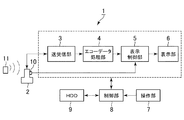
以下、本発明の実施形態について図1〜図8に基づいて説明する。図1に示す超音波診断装置1は、超音波プローブ2、送受信部3、エコーデータ処理部4、表示制御部5、表示部6、操作部7、制御部8、HDD(Hard Disk Drive:ハードディスクドライブ)9を備える。
Hereinafter, embodiments of the present invention will be described with reference to FIGS. 1 includes an
前記超音波プローブ2は、アレイ状に配置された複数の超音波振動子(図示省略)を有して構成され、この超音波振動子によって被検体に対して超音波を送信し、そのエコー信号を受信する。
The
前記超音波プローブ2には、例えばホール素子で構成される前記磁気センサ10が設けられている。この磁気センサ10により、例えば磁気発生コイルで構成される磁気発生部11から発生する磁気が検出されるようになっている。前記磁気センサ10における検出信号は、前記表示制御部5へ入力されるようになっている。前記磁気センサ10における検出信号は、図示しないケーブルを介して前記表示制御部5へ入力されてもよいし、無線で前記表示制御部5へ入力されてもよい。前記磁気発生部11及び前記磁気センサ10は、後述のように前記超音波プローブ2の位置及び傾きを検出するためのものであり、本発明における位置センサの実施の形態の一例である。
The
前記送受信部3は、前記超音波プローブ2から所定の走査条件で超音波を送信するための電気信号を、前記制御部8からの制御信号に基づいて前記超音波プローブ2に供給する。また、前記送受信部3は、前記超音波プローブ2で受信したエコー信号について、A/D変換、整相加算処理等の信号処理を行ない、信号処理後のエコーデータを前記エコーデータ処理部4へ出力する。
The transmission /
前記エコーデータ処理部4は、前記送受信部3から出力されたエコーデータに対し、超音波画像を作成するための処理を行なう。例えば、前記エコーデータ処理部4は、対数圧縮処理、包絡線検波処理等のBモード処理を行ってBモードデータを作成する。
The echo
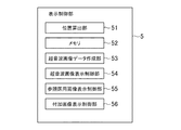
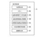
前記表示制御部5は、図2に示すように、位置算出部51、メモリ52、超音波画像データ作成部53、超音波画像表示制御部54、参照医用画像表示制御部55、付加画像表示制御部56を有する。前記位置算出部51は、前記磁気センサ10からの磁気検出信号に基づいて、前記磁気発生部11を原点とする三次元空間の座標系における前記超音波プローブ2の位置及び傾きの情報(以下、「プローブ位置情報」と云う)を算出する。さらに、前記位置算出部51は、前記プローブ位置情報に基づいてエコー信号の前記三次元空間の座標系における位置情報を算出する。前記磁気発生部11を原点とする三次元空間の座標系を、超音波画像UGの座標系と云うものとする。前記位置算出部51は、本発明における位置算出部の実施の形態の一例である。
As shown in FIG. 2, the
前記メモリ52は、例えばRAM(Random Access Memory)やROM(Read Only Memory)等の半導体メモリ(Memory)などで構成される。このメモリ52には、例えば前記エコーデータ処理部4から出力されて、後述するように前記超音波画像データ作成部53において超音波画像データに変換される前のデータなどが記憶される。前記超音波画像データに変換される前のデータを、ローデータ(Raw Data)と云うものとする。ローデータは、前記HDD9に記憶されるようになっていてもよい。
The
また、前記メモリ52には、予め取得された参照医用画像RGのボリュームデータが記憶されている。このボリュームデータは、前記HDD9に記憶されていてもよい。前記参照医用画像RGのボリュームデータは、参照医用画像RGの座標系における位置情報とともに前記メモリ52、前記HDD9に記憶される。
The
前記参照医用画像RGは、超音波画像以外の医用画像である。具体的には、前記参照医用画像RGは、例えばX線CT装置やMRI装置などで予め取得されたX線CT画像やMRI画像である。 The reference medical image RG is a medical image other than the ultrasonic image. Specifically, the reference medical image RG is an X-ray CT image or an MRI image acquired in advance by, for example, an X-ray CT apparatus or an MRI apparatus.
前記超音波画像データ作成部53は、前記エコーデータ処理部4から入力されたデータを、スキャンコンバータ(Scan Converter)によって走査変換して超音波画像データを作成する。
The ultrasonic image
前記超音波画像表示制御部54は、前記超音波画像データに基づいて、リアルタイムの超音波画像UGを前記表示部6に表示させる。
The ultrasonic image
前記参照医用画像表示制御部55は、参照医用画像表示制御機能を実行する。具体的には、前記参照医用画像表示制御部55は、前記位置算出部51で算出されたエコー信号の位置に対応する参照医用画像RGを表示させる。また、前記参照医用画像表示制御部55は、後述するように、前記ボリュームデータに基づいて前記操作部7で入力された断面の参照医用画像RGを表示させる。前記参照医用画像表示制御部55は、本発明における参照医用画像表示制御部の実施の形態の一例である。
The reference medical image
前記付加画像表示制御部56は、後述するように、ボディマークBMを前記表示部6に表示させるとともに、このボディマークBM上にプローブマークPMを表示させる(例えば図5参照)。前記プローブマークPMは、本発明における指示マーカ(marker)の実施の形態の一例である。また、前記付加画像表示制御部56は、本発明における指示マーカ表示制御部の実施の形態の一例である。
As will be described later, the additional image
前記表示部6は、LCD(Liquid Crystal Display)やCRT(Cathode Ray Tube)などで構成される。前記操作部7は、操作者が指示や情報を入力するためのキーボード及びポインティングデバイス(図示省略)などを含んで構成されている。前記操作部7は、本発明における入力部の実施の形態の一例である。
The
前記制御部8は、特に図示しないがCPU(Central Processing Unit)を有して構成される。この制御部8は、前記HDD9に記憶された制御プログラムを読み出し、前記超音波診断装置1の各部における機能を実行させる。
The
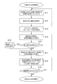
さて、本例の超音波診断装置1の作用について図3のフローチャートに基づいて説明する。ここでの作用としては、超音波画像UGの座標系と参照医用画像RGの座標系との位置合わせ処理を説明する。
Now, the operation of the ultrasonic
先ず、図3のステップS1では、操作者は、特徴部位を含む断面の参照医用画像RGを表示させる入力を前記操作部7において行なう。具体的には、先ず前記付加画像表示制御部56が、表示させる断面の候補を前記表示部6に複数表示させる。次に、操作者は表示された候補の中から表示させたい断面を前記操作部7のトラックボール等を用いてカーソルで選択する入力を行なう。
First, in step S1 in FIG. 3, the operator performs an input on the operation unit 7 to display a cross-sectional reference medical image RG including a characteristic part. Specifically, first, the additional image
ここで、表示させる断面の候補は、参照医用画像RGのボリュームデータにおいて予め記憶されており、被検体における位置が特定されているものとする。例えば、肝臓のボリュームデータであれば、特徴部位として血管の分岐部分(例えば、門脈本幹と左葉枝水平部との分岐部分など)の断面が記憶されている。前記付加画像表示制御部56は、記憶されている断面の候補をアイコンや文字などで前記表示部6に表示させる。
Here, it is assumed that the candidate for the cross section to be displayed is stored in advance in the volume data of the reference medical image RG and the position in the subject is specified. For example, in the case of liver volume data, a cross-section of a blood vessel bifurcation (for example, a bifurcation of a portal trunk and a left lobe horizontal portion) is stored as a characteristic part. The additional image
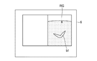
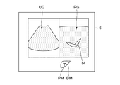
次に、ステップS2では、前記参照医用画像表示制御部55は、ステップS1で選択された断面の参照医用画像RGを、図4に示すように前記表示部6に表示させる。図4において、符号blは血管を示している。
Next, in step S2, the reference medical image
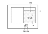
次に、ステップS3では、図5に示すように、前記付加画像表示制御部56は、前記表示部6にボディマークBM及びプローブマークPMを表示させる。本例では、前記ボディマークBMは肝臓を示すボディマークである。このボディマークBM上に表示されたプローブマークPMは、ステップS2において選択された断面の被検体における位置を示している。
Next, in step S3, as shown in FIG. 5, the additional image
前記ボディマークBMにおける前記プローブマークPMの位置は、前記参照医用画像RGの断面毎に記憶されている。前記ステップS3では、前記ステップS2で選択された断面に応じた位置のプローブマークPMが表示される。 The position of the probe mark PM in the body mark BM is stored for each cross section of the reference medical image RG. In step S3, the probe mark PM at a position corresponding to the cross section selected in step S2 is displayed.
ちなみに、前記ボディマークBM及び前記プローブマークPMは、前記ステップS2において参照医用画像RGが表示されると同時に表示されてもよい。 Incidentally, the body mark BM and the probe mark PM may be displayed simultaneously with the display of the reference medical image RG in the step S2.
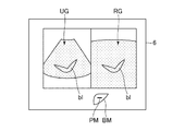
次にステップS4では、前記超音波プローブ2を被検体の体表面に当接させて超音波の送受信を開始する。そして、前記超音波画像表示制御部54は、エコー信号に基づいて作成された超音波画像UGを、図6に示すように前記表示部6に表示させる。前記超音波画像UGは例えばBモード画像である。前記超音波画像UGは、前記参照医用画像RGと並列に前記表示部6に表示される。ちなみに、前記超音波画像UGの断面と前記参照医用画像RGの断面は平行であるものとする。
Next, in step S4, the
ステップS4において超音波画像UGが表示されると、ステップS5では、操作者は前記超音波プローブ2を移動させて、図7に示すように前記参照医用画像RGと同一断面の超音波画像UGを表示させる。操作者は、前記プローブマークPMを参照することにより、被検体においてどの場所に前記超音波プローブ2を位置させればよいかを容易に把握することができるので、前記参照医用画像RGと同一の断面を容易に発見することができる。
When the ultrasonic image UG is displayed in step S4, in step S5, the operator moves the
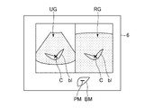
ステップS5において前記参照医用画像RGと同一断面についての超音波画像UGが表示されると、ステップS6において操作者は、図8に示すように、前記超音波画像UG及び前記参照医用画像RGにおいて同一部位と思われる部分をカーソルCにより指定する。ここでは、カーソルCにより血管blの分岐部分が指定される。具体的には、操作者は前記超音波画像UG及び前記参照医用画像RG上に表示されたカーソルCを前記操作部7のトラックボール等を用いて移動させて血管の分岐部分を指定する。 When the ultrasonic image UG with respect to the same cross section as the reference medical image RG is displayed in step S5, in step S6, the operator matches the ultrasonic image UG and the reference medical image RG as shown in FIG. A part that is considered to be a part is designated by the cursor C. Here, the branch portion of the blood vessel bl is designated by the cursor C. Specifically, the operator moves the cursor C displayed on the ultrasonic image UG and the reference medical image RG using a trackball or the like of the operation unit 7 and designates a branch portion of the blood vessel.
ここで、前記参照医用画像RGのデータは位置情報を有している。従って、上述のように前記超音波画像UGと前記参照医用画像RGとで同一位置と思われる点を指定すると、これら超音波画像UGの座標系と参照医用画像RGの座標系との対応位置が特定される。これにより、前記超音波画像UGの座標系と前記参照医用画像RGの座標系との座標変換が可能になる。以上により位置合わせ処理が終了し、前記参照医用画像表示制御部55は、前記位置算出部51で算出されたエコー信号の位置に対応する位置を前記ボリュームデータにおいて特定して参照医用画像RGを表示させる。これにより、前記表示部6には、リアルタイムの超音波画像UGに追従するようにしてこの超音波画像UGと同一断面の参照医用画像RGが表示される。
Here, the data of the reference medical image RG has position information. Therefore, as described above, when a point that is considered to be the same position in the ultrasound image UG and the reference medical image RG is designated, the corresponding position between the coordinate system of the ultrasound image UG and the coordinate system of the reference medical image RG is determined. Identified. Thereby, coordinate conversion between the coordinate system of the ultrasonic image UG and the coordinate system of the reference medical image RG becomes possible. The alignment processing is completed as described above, and the reference medical image
以上説明した本例の超音波診断装置1によれば、被検体における位置が特定された断面であって、操作者によって選択された断面についての参照医用画像RGが、位置合わせの際に表示されるので、位置合わせを行なうための特徴部位を含む参照医用画像RGの断面を探す手間が不要になる。従って、操作者は、被検体において超音波画像UGを表示させるべき断面、すなわち前記参照医用画像RGと同一断面を短時間で容易に特定することができる。このように、参照医用画像RGと同一断面の超音波画像UGを容易に表示させることができるので、位置合わせを簡単に行なうことができる。
According to the ultrasonic
また、前記ステップS3において前記ボディマークBM及び前記プローブマークPMが表示されるので、操作者はこれを頼りにして前記超音波プローブ2を移動させれば参照医用画像RGと同一断面の超音波画像UGを容易に表示させることができる。
In addition, since the body mark BM and the probe mark PM are displayed in the step S3, if the operator relies on this to move the
(第二実施形態)
次に、第二実施形態について説明する。以下、第一実施形態と異なる事項について説明する。
(Second embodiment)
Next, a second embodiment will be described. Hereinafter, matters different from the first embodiment will be described.
本例では、前記表示制御部5は、図9に示すように、位置算出部51、メモリ52、超音波画像データ作成部53、超音波画像表示制御部54、参照医用画像表示制御部55、付加画像表示制御部56の他、距離算出部57を有する。この距離算出部57については後述する。
In this example, as shown in FIG. 9, the
第二実施形態の作用について図10のフローチャートに基づいて説明する。本例では、前記超音波画像UG及び前記参照医用画像RGにおけるカーソルCによる指定を複数断面について行なうことができる。前記超音波画像UG及び前記参照医用画像RGにおける対応位置を複数断面について特定することで、位置合わせの精度を向上させることができる。 The operation of the second embodiment will be described based on the flowchart of FIG. In this example, designation by the cursor C in the ultrasonic image UG and the reference medical image RG can be performed for a plurality of cross sections. By specifying corresponding positions in the ultrasonic image UG and the reference medical image RG for a plurality of cross sections, it is possible to improve alignment accuracy.
具体的に説明する。ステップS11〜S14については、上述のステップS1〜S4と同一の処理である。ステップS14において超音波画像UGが表示されると、ステップS15では、前記制御部8は、前記超音波画像UG及び前記参照医用画像RGにおいて同一部位の指定が行われているか否かを判定する。この同一部位の指定は、後述のステップS18における処理である。
This will be specifically described. Steps S11 to S14 are the same as steps S1 to S4 described above. When the ultrasound image UG is displayed in step S14, in step S15, the
ステップS15において、同一部位の指定が行われていないと判定された場合(ステップS15で「NO」)、ステップS17の処理へ移行する。一方、ステップS15において、同一部位の指定が行われていると判定された場合(ステップS15で「YES」)、ステップS16の処理へ移行する。 If it is determined in step S15 that the same part is not designated ("NO" in step S15), the process proceeds to step S17. On the other hand, if it is determined in step S15 that the same part is designated ("YES" in step S15), the process proceeds to step S16.
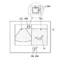
ステップS16では、前記付加画像表示制御部56は、図11に示すように、前記表示部6に距離マークDMを表示させる。この距離マークDMは、ステップS14で表示された超音波画像UGの断面の被検体における位置(超音波の送受信面の位置)と、ステップS12で表示された参照医用画像RGの断面の被検体における位置との距離Dを示す表示であり、本発明における距離表示の実施の形態の一例である。また、本例では前記付加画像表示制御部56は、本発明における距離表示制御部の実施の形態の一例である。
In step S16, the additional image
前記距離Dは、前記距離算出部57により算出される。具体的には、先ず前記距離算出部57は、前記位置算出部51で算出された前記超音波画像UGの断面の位置に対応する位置を、参照医用画像RGのボリュームデータにおいて特定する。ここでは、超音波画像UGの座標系と参照医用画像RGの座標系との対応位置が特定されているので、前記超音波画像UGの座標系と前記参照医用画像RGの座標系との座標変換が可能であり、前記超音波画像UGの断面に対応する位置を、前記参照医用画像RGのボリュームデータにおいて特定することができる。
The distance D is calculated by the
前記距離算出部57は、このようにして前記参照医用画像RGのボリュームデータにおいて前記超音波画像UGの断面の位置が特定されると、この超音波画像UGの断面と前記参照医用画像RGの断面との距離Dを算出する。
When the position of the cross section of the ultrasonic image UG is specified in the volume data of the reference medical image RG in this way, the
前記付加画像表示制御部56は、前記距離算出部57によって算出された距離Dに基づいて前記距離マークDMを表示させる。この距離マークDMは、本例では距離Dに応じた面積を有する四角形の図形である。前記距離マークDMの面積は、距離Dが長くなるほど大きくなり、距離Dが短くなるほど小さくなる。
The additional image
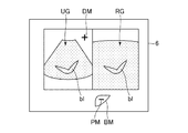
ただし、前記距離マークDMは、前記距離Dが零である場合、すなわち前記参照医用画像RGと同一断面の超音波画像UGが表示されている場合、「+」(プラス)印になる(図12参照)。 However, when the distance D is zero, that is, when an ultrasonic image UG having the same cross section as the reference medical image RG is displayed, the distance mark DM becomes a “+” (plus) mark (FIG. 12). reference).
前記ステップS16で前記距離マークDMが表示されるか、前記ステップS15で「NO」と判定された場合、ステップS17の処理へ移行し、上述のステップS5と同様に参照医用画像RGと同一断面の超音波画像UGを表示させる。前記ステップS16で前記距離マークDMが表示されていれば、操作者は、前記プローブマークPMの他、前記距離マークDMを参照することにより、前記参照医用画像RGと同一の断面を一層容易に発見することができる。 If the distance mark DM is displayed in step S16 or if “NO” is determined in step S15, the process proceeds to step S17, and the same cross section as the reference medical image RG as in step S5 described above. An ultrasonic image UG is displayed. If the distance mark DM is displayed in step S16, the operator can more easily find the same cross section as the reference medical image RG by referring to the distance mark DM in addition to the probe mark PM. can do.
前記ステップS16で前記距離マークDMが表示されている場合、前記ステップS17で前記参照医用画像RGと同一断面の超音波画像UGが表示されると、図12に示すように、前記距離マークDMは「+」印となる。 When the distance mark DM is displayed in the step S16, when the ultrasonic image UG having the same cross section as the reference medical image RG is displayed in the step S17, the distance mark DM is displayed as shown in FIG. “+” Mark.
次に、ステップS18の処理へ移行する。このステップS18については、上述のステップS6と同一の処理である。 Next, the process proceeds to step S18. This step S18 is the same process as step S6 described above.
次にステップS19では、前記付加画像表示制御部56は、別の断面の画像を表示させるか否かを問うメッセージの画像(図示省略)を前記表示部6に表示させる。操作者は、別の断面の画像を表示させるか、表示させないかを指示する入力を前記操作部7によって入力する。
In step S19, the additional image
前記ステップS19において、別の断面の画像を表示させる入力が行われた場合(前記ステップS19で「YES」)、前記ステップS11の処理へ移行し、再び上述のステップを繰り返す。一方、前記ステップS19において、別の断面の画像を表示させない入力が行われた場合(前記ステップS19で「NO」)、位置合わせ処理は終了する。 In step S19, when an input for displaying an image of another cross section is performed (“YES” in step S19), the process proceeds to step S11, and the above steps are repeated again. On the other hand, if an input not to display another cross-sectional image is performed in step S19 ("NO" in step S19), the alignment process ends.
以上、本発明を前記実施形態によって説明したが、本発明はその主旨を変更しない範囲で種々変更実施可能なことはもちろんである。例えば、上述のステップS1、S11において、特徴部位を含む断面の参照医用画像RGを表示させる入力は、操作者が表示させたい断面を選択する入力であれば上述の例に限られるものではなく、例えば特徴部位を文字で入力してもよい。 As mentioned above, although this invention was demonstrated by the said embodiment, of course, this invention can be variously implemented in the range which does not change the main point. For example, in the above-described steps S1 and S11, the input for displaying the reference medical image RG of the cross section including the characteristic part is not limited to the above example as long as the input is for selecting the cross section to be displayed by the operator. For example, the characteristic part may be input as characters.
また、特徴部位を含む断面の参照医用画像RGを表示させる入力は、操作者が表示させたい断面を選択する入力に限られるものではなく、予め取得された前記参照医用画像のボリュームデータにおける特徴部位を含む断面の中から、プリセットされた断面を自動的に表示させるための入力であってもよい。この場合、第二実施形態では、前記ステップS18において、一つの断面について、前記超音波画像UG及び前記参照医用画像RGにおける同一部位の指定が終了すると、予め設定された順番で、別の断面の参照医用画像RGが表示されるようにしてもよい。 Further, the input for displaying the reference medical image RG of the cross section including the characteristic part is not limited to the input for selecting the cross section that the operator wants to display, but the characteristic part in the volume data of the reference medical image acquired in advance. An input for automatically displaying a preset cross section from among cross sections including In this case, in the second embodiment, in step S18, when the same part in the ultrasonic image UG and the reference medical image RG is specified for one cross section, the other cross sections are arranged in a preset order. The reference medical image RG may be displayed.
また、前記ボディマークBM及び前記プローブマークPMは一例であり上述のものに限られるものではない。例えば、前記ボディマークBMは、人体の上半身を示すマーク等であってもよい。 The body mark BM and the probe mark PM are examples and are not limited to those described above. For example, the body mark BM may be a mark indicating the upper body of the human body.
なお、前記超音波画像UGの断面と前記参照医用画像RGの断面とが平行ではない場合、少なくとも異なる三断面について、前記超音波画像UG及び前記参照医用画像RGにおける対応位置を前記カーソルCによって指定することにより、前記超音波画像UGの座標系と前記参照医用画像RGの座標系との対応位置が特定される。この場合、予め記憶された断面についての参照医用画像RGを順次表示させ、それぞれの断面について、対応断面の超音波画像UGを表示させて前記カーソルCの指定を行なう。この時、対応する前記ボディマークBM及び前記プローブマークPMを表示させてもよい。 When the cross section of the ultrasonic image UG and the cross section of the reference medical image RG are not parallel, the corresponding positions in the ultrasonic image UG and the reference medical image RG are designated by the cursor C for at least three different cross sections. Thus, the corresponding position between the coordinate system of the ultrasonic image UG and the coordinate system of the reference medical image RG is specified. In this case, the reference medical image RG for the cross-section stored in advance is sequentially displayed, and for each cross-section, the ultrasonic image UG of the corresponding cross-section is displayed to designate the cursor C. At this time, the corresponding body mark BM and probe mark PM may be displayed.
1 超音波診断装置
7 操作部(入力部)
10 磁気センサ(位置センサ)
11 磁気発生部(位置センサ)
51 位置算出部
55 参照医用画像表示制御部
56 付加画像表示制御部(指示マーカ表示制御部、距離表示制御部)
1 Ultrasonic diagnostic equipment 7 Operation part (input part)
10 Magnetic sensor (position sensor)
11 Magnetic generator (position sensor)
51
Claims (6)
予め取得された参照医用画像のボリュームデータに基づいて、前記入力部で入力された断面の参照医用画像を表示部に表示させる参照医用画像表示制御部と、
表示された前記参照医用画像の前記被検体における位置を示す指示マーカを前記表示部に表示させる指示マーカ表示制御部と、
前記被検体に対して超音波を送信しエコー信号を受信する超音波プローブと、
前記エコー信号に基づいてリアルタイムの超音波画像を前記表示部に表示させる超音波画像表示制御部と、
前記超音波プローブの位置を検出するための位置センサと、
前記位置センサの位置検出情報に基づいて、前記超音波画像の座標系における前記エコー信号の位置を算出する位置算出部と、
表示された前記参照医用画像及び前記超音波画像における前記特徴部位に関する同一部位を操作者が指定する指定部とを備え、
前記参照医用画像表示制御部は、前記指定部を用いた前記同一部位の指定に基づいて、前記リアルタイムの超音波画像に追従するように、前記超音波画像と同一断面の前記参照医用画像を前記表示部に表示させることを特徴とする超音波診断装置。 An input unit for performing an input to display a reference medical image of a cross section including a characteristic part, which is a cross section whose position in the subject is specified;
A reference medical image display control unit that displays a reference medical image of a cross section input by the input unit on a display unit based on volume data of a reference medical image acquired in advance;
An instruction marker display control unit that causes the display unit to display an instruction marker indicating the position of the displayed reference medical image in the subject;
An ultrasonic probe that transmits ultrasonic waves to the subject and receives echo signals;
An ultrasonic image display control unit for displaying a real-time ultrasonic image on the display unit based on the echo signal;
A position sensor for detecting the position of the ultrasonic probe;
A position calculation unit that calculates the position of the echo signal in the coordinate system of the ultrasonic image based on position detection information of the position sensor;
A designation unit that allows an operator to designate the same part related to the characteristic part in the displayed reference medical image and the ultrasound image;
The reference medical image display control unit converts the reference medical image having the same cross section as the ultrasonic image to follow the real-time ultrasonic image based on the designation of the same part using the designation unit. An ultrasonic diagnostic apparatus characterized by being displayed on a display unit.
被検体における位置が特定された断面であって特徴部位を含む断面の参照医用画像を表示させる入力を受けて、予め取得された参照医用画像のボリュームデータに基づいて、前記断面の参照医用画像を表示部に表示させる参照医用画像表示制御機能と、
表示された前記参照医用画像の前記被検体における位置を示す指示マーカを前記表示部に表示させる指示マーカ表示制御機能と、
超音波プローブが受信したエコー信号に基づいてリアルタイムの超音波画像を前記表示部に表示させる超音波画像表示機能と、
前記超音波プローブの位置を検出するための位置センサの位置検出情報に基づいて、前記超音波画像の座標系における前記エコー信号の位置を算出する位置算出機能とを実行させるとともに、
前記参照医用画像表示制御機能は、更に、操作者による表示された前記参照医用画像及び前記超音波画像における前記特徴部位に関する同一部位の指定に基づいて、前記リアルタイムの超音波画像に追従するように、前記超音波画像と同一断面の前記参照医用画像を前記表示部に表示させる機能を実行させることを特徴とする超音波診断装置の制御プログラム。 On the computer,
Based on the volume data of the reference medical image acquired in advance, the reference medical image of the cross section is received based on the volume data of the reference medical image acquired in advance. A reference medical image display control function to be displayed on the display unit;
An instruction marker display control function for causing the display unit to display an instruction marker indicating the position of the displayed reference medical image in the subject;
An ultrasonic image display function for displaying a real-time ultrasonic image on the display unit based on an echo signal received by the ultrasonic probe;
Based on position detection information of a position sensor for detecting the position of the ultrasonic probe, a position calculation function for calculating the position of the echo signal in the coordinate system of the ultrasonic image is executed, and
The reference medical image display control function further follows the real-time ultrasonic image based on designation of the same part regarding the characteristic part in the reference medical image and the ultrasonic image displayed by the operator. A control program for an ultrasonic diagnostic apparatus, which executes a function of causing the display unit to display the reference medical image having the same cross section as the ultrasonic image.
Priority Applications (3)
| Application Number | Priority Date | Filing Date | Title |
|---|---|---|---|
| JP2011120467A JP5717543B2 (en) | 2011-05-30 | 2011-05-30 | Ultrasonic diagnostic apparatus and control program therefor |
| KR1020120056457A KR101629058B1 (en) | 2011-05-30 | 2012-05-29 | Ultrasonic diagnosis apparatus and program for controlling the same |
| US13/483,507 US9259204B2 (en) | 2011-05-30 | 2012-05-30 | Ultrasound diagnostic apparatus and method of displaying medical image thereof |
Applications Claiming Priority (1)
| Application Number | Priority Date | Filing Date | Title |
|---|---|---|---|
| JP2011120467A JP5717543B2 (en) | 2011-05-30 | 2011-05-30 | Ultrasonic diagnostic apparatus and control program therefor |
Publications (2)
| Publication Number | Publication Date |
|---|---|
| JP2012245230A JP2012245230A (en) | 2012-12-13 |
| JP5717543B2 true JP5717543B2 (en) | 2015-05-13 |
Family
ID=47262197
Family Applications (1)
| Application Number | Title | Priority Date | Filing Date |
|---|---|---|---|
| JP2011120467A Active JP5717543B2 (en) | 2011-05-30 | 2011-05-30 | Ultrasonic diagnostic apparatus and control program therefor |
Country Status (3)
| Country | Link |
|---|---|
| US (1) | US9259204B2 (en) |
| JP (1) | JP5717543B2 (en) |
| KR (1) | KR101629058B1 (en) |
Families Citing this family (9)
| Publication number | Priority date | Publication date | Assignee | Title |
|---|---|---|---|---|
| WO2014034948A1 (en) * | 2012-09-03 | 2014-03-06 | 株式会社東芝 | Ultrasonic diagnostic apparatus and image processing method |
| JP6203514B2 (en) * | 2013-03-29 | 2017-09-27 | ジーイー・メディカル・システムズ・グローバル・テクノロジー・カンパニー・エルエルシー | Ultrasonic diagnostic apparatus and control program therefor |
| JP6397269B2 (en) * | 2013-09-06 | 2018-09-26 | キヤノン株式会社 | Image processing apparatus and image processing method |
| KR20160012590A (en) * | 2014-07-24 | 2016-02-03 | 삼성메디슨 주식회사 | Ultrasound imaging apparatus and controlling method thereof |
| JP6293619B2 (en) * | 2014-08-28 | 2018-03-14 | ジーイー・メディカル・システムズ・グローバル・テクノロジー・カンパニー・エルエルシー | Image processing method, apparatus, and program |
| US10991069B2 (en) * | 2014-10-08 | 2021-04-27 | Samsung Electronics Co., Ltd. | Method and apparatus for registration of medical images |
| JP6490820B2 (en) * | 2015-09-02 | 2019-03-27 | 株式会社日立製作所 | Ultrasonic imaging apparatus, image processing apparatus, and method |
| JP6681778B2 (en) * | 2016-04-27 | 2020-04-15 | ゼネラル・エレクトリック・カンパニイ | Ultrasonic image display device and its control program |
| CN110892452B (en) | 2017-05-04 | 2024-11-22 | Mim软件有限公司 | Systems and methods for predictive fusion |
Family Cites Families (14)
| Publication number | Priority date | Publication date | Assignee | Title |
|---|---|---|---|---|
| EP0997109B1 (en) | 1993-04-26 | 2003-06-18 | ST. Louis University | Indicating the position of a surgical probe |
| JP3752446B2 (en) | 2001-11-29 | 2006-03-08 | ジーイー・メディカル・システムズ・グローバル・テクノロジー・カンパニー・エルエルシー | Ultrasonic diagnostic equipment |
| JP4088104B2 (en) * | 2002-06-12 | 2008-05-21 | 株式会社東芝 | Ultrasonic diagnostic equipment |
| JP2004105638A (en) * | 2002-09-20 | 2004-04-08 | Shimadzu Corp | Ultrasound diagnostic equipment |
| EP2460474B1 (en) | 2003-05-08 | 2015-12-16 | Hitachi Medical Corporation | Reference image display method for ultrasonography and ultrasonic diagnosis apparatus |
| US7720520B2 (en) | 2004-12-01 | 2010-05-18 | Boston Scientific Scimed, Inc. | Method and system for registering an image with a navigation reference catheter |
| JP2006158799A (en) | 2004-12-10 | 2006-06-22 | Ge Medical Systems Global Technology Co Llc | Ultrasonic imaging apparatus |
| EP1935344B1 (en) * | 2005-10-07 | 2013-03-13 | Hitachi Medical Corporation | Image displaying method and medical image diagnostic system |
| CN101291635B (en) | 2005-10-20 | 2013-03-27 | 直观外科手术操作公司 | Auxiliary image display and manipulation on computer display screens in medical robotic systems |
| US8303505B2 (en) | 2005-12-02 | 2012-11-06 | Abbott Cardiovascular Systems Inc. | Methods and apparatuses for image guided medical procedures |
| EP1881453A3 (en) * | 2006-07-18 | 2009-07-22 | Kabushiki Kaisha Toshiba | A medical image-processing apparatus and a method for processing medical images |
| JP2008073305A (en) * | 2006-09-22 | 2008-04-03 | Gifu Univ | Ultrasonic breast diagnosis system |
| JP2009112356A (en) | 2007-11-02 | 2009-05-28 | Ge Medical Systems Global Technology Co Llc | Ultrasonic diagnostic apparatus |
| JP2010194087A (en) | 2009-02-25 | 2010-09-09 | Ge Medical Systems Global Technology Co Llc | Ultrasonic diagnostic apparatus and program |
-
2011
- 2011-05-30 JP JP2011120467A patent/JP5717543B2/en active Active
-
2012
- 2012-05-29 KR KR1020120056457A patent/KR101629058B1/en active Active
- 2012-05-30 US US13/483,507 patent/US9259204B2/en active Active
Also Published As
| Publication number | Publication date |
|---|---|
| US20130184585A9 (en) | 2013-07-18 |
| KR101629058B1 (en) | 2016-06-09 |
| JP2012245230A (en) | 2012-12-13 |
| US20120310092A1 (en) | 2012-12-06 |
| US9259204B2 (en) | 2016-02-16 |
| KR20120134042A (en) | 2012-12-11 |
Similar Documents
| Publication | Publication Date | Title |
|---|---|---|
| JP5717543B2 (en) | Ultrasonic diagnostic apparatus and control program therefor | |
| JP5574742B2 (en) | Ultrasonic diagnostic equipment | |
| JP2022009022A (en) | Ultrasound system and method for breast tissue imaging | |
| JP5601684B2 (en) | Medical imaging device | |
| JP5682873B2 (en) | Ultrasonic diagnostic equipment | |
| JP5829022B2 (en) | Ultrasonic diagnostic equipment | |
| JP2014161598A (en) | Ultrasonic diagnostic apparatus and control program for the same | |
| JP2010253031A (en) | Ultrasonic diagnostic equipment | |
| JP2014161478A (en) | Ultrasonic diagnostic apparatus and control program therefor | |
| JP2014195729A (en) | Ultrasound diagnosis system | |
| JP6382031B2 (en) | Ultrasonic diagnostic apparatus and control program therefor | |
| JP6681778B2 (en) | Ultrasonic image display device and its control program | |
| JP6883432B2 (en) | Ultrasonic image display device and its control program | |
| JP2006081640A (en) | Ultrasonic imaging device, image processor and program | |
| JP6695475B2 (en) | Ultrasonic diagnostic equipment | |
| JP5645742B2 (en) | Ultrasonic diagnostic apparatus and control program therefor | |
| JP6293429B2 (en) | Data analysis apparatus, program for data analysis apparatus and ultrasonic diagnostic apparatus | |
| JP6588694B2 (en) | Ultrasonic diagnostic equipment | |
| JP6203514B2 (en) | Ultrasonic diagnostic apparatus and control program therefor | |
| JP2016022124A (en) | Ultrasonic diagnostic device and control program thereof | |
| JP6234043B2 (en) | Ultrasonic diagnostic apparatus and control program therefor | |
| JP6389084B2 (en) | Ultrasonic diagnostic apparatus and control program therefor | |
| JP6420678B2 (en) | Ultrasonic diagnostic apparatus and control program therefor | |
| JP5908784B2 (en) | Position detection apparatus and ultrasonic image display apparatus | |
| JP2012231810A (en) | Ultrasonic diagnostic apparatus, and control program therefor |
Legal Events
| Date | Code | Title | Description |
|---|---|---|---|
| A625 | Written request for application examination (by other person) |
Free format text: JAPANESE INTERMEDIATE CODE: A625 Effective date: 20131127 |
|
| A977 | Report on retrieval |
Free format text: JAPANESE INTERMEDIATE CODE: A971007 Effective date: 20140625 |
|
| A131 | Notification of reasons for refusal |
Free format text: JAPANESE INTERMEDIATE CODE: A131 Effective date: 20140630 |
|
| A521 | Request for written amendment filed |
Free format text: JAPANESE INTERMEDIATE CODE: A523 Effective date: 20140905 |
|
| TRDD | Decision of grant or rejection written | ||
| A01 | Written decision to grant a patent or to grant a registration (utility model) |
Free format text: JAPANESE INTERMEDIATE CODE: A01 Effective date: 20150216 |
|
| A61 | First payment of annual fees (during grant procedure) |
Free format text: JAPANESE INTERMEDIATE CODE: A61 Effective date: 20150317 |
|
| R150 | Certificate of patent or registration of utility model |
Ref document number: 5717543 Country of ref document: JP Free format text: JAPANESE INTERMEDIATE CODE: R150 |
|
| R250 | Receipt of annual fees |
Free format text: JAPANESE INTERMEDIATE CODE: R250 |
|
| R250 | Receipt of annual fees |
Free format text: JAPANESE INTERMEDIATE CODE: R250 |
|
| R250 | Receipt of annual fees |
Free format text: JAPANESE INTERMEDIATE CODE: R250 |
|
| R250 | Receipt of annual fees |
Free format text: JAPANESE INTERMEDIATE CODE: R250 |
|
| R250 | Receipt of annual fees |
Free format text: JAPANESE INTERMEDIATE CODE: R250 |
|
| R250 | Receipt of annual fees |
Free format text: JAPANESE INTERMEDIATE CODE: R250 |
|
| R250 | Receipt of annual fees |
Free format text: JAPANESE INTERMEDIATE CODE: R250 |
|
| R250 | Receipt of annual fees |
Free format text: JAPANESE INTERMEDIATE CODE: R250 |