JP5714643B2 - Tile-like fixed rail - Google Patents
Tile-like fixed rail Download PDFInfo
- Publication number
- JP5714643B2 JP5714643B2 JP2013095675A JP2013095675A JP5714643B2 JP 5714643 B2 JP5714643 B2 JP 5714643B2 JP 2013095675 A JP2013095675 A JP 2013095675A JP 2013095675 A JP2013095675 A JP 2013095675A JP 5714643 B2 JP5714643 B2 JP 5714643B2
- Authority
- JP
- Japan
- Prior art keywords
- tile
- rail
- shaped member
- fixed
- fitting portion
- Prior art date
- Legal status (The legal status is an assumption and is not a legal conclusion. Google has not performed a legal analysis and makes no representation as to the accuracy of the status listed.)
- Active
Links
Images


Description
本発明は、建物の外壁や内壁等にタイル状の部材を固定するためのレールに関する。 The present invention relates to a rail for fixing a tile-shaped member to an outer wall or an inner wall of a building.
この種の従来技術として、例えば、乾式タイル張り工法に用いられるタイル取付装置が知られている。
このタイル取付装置100は、図7のように建築物の壁面Wに据え付けられる長尺板部材101と、長尺板部材101に直交して固定される短尺のタイル係合部材102とを備えている。また、タイル係合部材102には、タイル裏面の溝部201に係合する上下一対の突出片102a,102bが設けられ、これら突出片102a,102bにタイルの溝部201を嵌め込むことで壁面Wにタイル200が固定される。
As this type of prior art, for example, a tile mounting device used in a dry tile method is known.
The tile mounting apparatus 100 includes a
詳しくは、上下一対の突出片102a,102bのうち、下側の突出片102bにバネ性が付与され、上側の突出片102aにタイル裏面の溝部201を引っ掛けた後、この状態からタイル200の下部を下側の突出片102bに向かって強く押し込むとタイル200が填り込む。すなわち、タイル裏面の溝部201がバネ性を有する突出片102bの抗力に打ち勝って、突出片102bの裏側に填り込む構造になっている。
Specifically, of the pair of upper and
このように構成されたタイル取付装置は、モルタル等を用いること無くタイルを壁面に固定できるため、熟練の技術を要せずとも短時間且つ容易にタイル面を形成できる。また、モルタルの経年劣化による剥離もなく、高所ではタイルの落下防止対策としても有効である。なお、図7中103は、目地を埋める目地モルタルであり、図7中104は、タイル係合部材102を壁面Wに固定するためのネジである。また、突出片102a,102bと溝部201との間に接着材を充填して補強する旨の記載もある。
Since the tile mounting apparatus configured as described above can fix the tile to the wall surface without using mortar or the like, the tile surface can be easily formed in a short time without requiring a skilled technique. Moreover, there is no peeling due to aging of the mortar, and it is effective as a measure to prevent the tile from dropping at high places. 7 is a joint mortar for filling the joint, and 104 in FIG. 7 is a screw for fixing the
ところで、タイルを壁面に固定する際、その固定強度も重要であるが、取り付け後の美観も重要である。すなわち、上下左右方向に整然とタイルが並ぶ様にタイルを取り付ける必要がある。 By the way, when fixing a tile to a wall surface, the fixing strength is also important, but the aesthetic appearance after attachment is also important. In other words, it is necessary to attach the tiles so that the tiles are neatly arranged in the vertical and horizontal directions.
この点、従来のタイル取付装置は、壁面に対して規則正しく配置される長尺板部材やタイル係合部材によって、ある程度の取り付け精度は得られるものの、個々のタイルに着目すると、必ずしも精度良く取り付けられているとは言い難かった。すなわち、従来のタイル取付装置は、タイルの位置ずれや不陸(タイルの浮き沈み)を調整する手段が無く、タイルの取付精度は、壁面の平坦度やタイルの加工精度に委ねられていた。 In this regard, the conventional tile mounting apparatus can be mounted with a high degree of accuracy when focusing on individual tiles, although a certain level of mounting accuracy can be obtained by the long plate members and tile engaging members that are regularly arranged on the wall surface. It was hard to say. That is, the conventional tile mounting apparatus has no means for adjusting the displacement and unevenness of the tile (the ups and downs of the tile), and the tile mounting accuracy is left to the flatness of the wall surface and the processing accuracy of the tile.
本発明は、上記した課題を考慮してなされたもので、タイル等の部材を固定する際、十分な固定強度を確保すると共に個々の部材を精度良く取り付け可能な固定レールの提供を課題とする。 The present invention has been made in consideration of the above-described problems, and it is an object of the present invention to provide a fixed rail capable of securing a sufficient fixing strength and attaching individual members with high accuracy when fixing members such as tiles. .
上記した技術的課題を解決するため、本発明は、施工対象面にタイル状部材を固定するための固定レールであって、
施工対象面に取り付けられる中央部のレール本体と、
前記レール本体の表面から突設されると共に、前記タイル状部材の裏面に設けられ、開口部よりも内部が拡大するように形成された溝部に嵌合する嵌合部と、
前記嵌合部の基部から施工対象面に沿うように延設される支持部と、
を有し、
前記嵌合部は弾性を有し、前記レール本体の両側縁に設けられ、かつ、薄板からなるレール本体の側縁を往復曲成して形成される二重構造であって、前記支持部から曲げ起こし、さらに曲げ戻して前記レール本体にまで到達し、かつこの嵌合部の先端にラッチ状の突起を備え、
前記タイル状部材が前記固定レールに固定される際、前記開口部の縁部は、前記ラッチ状の突起を弾性変形させつつ、これを乗り越えることを特徴とする。
In order to solve the above technical problem, the present invention is a fixed rail for fixing a tile-shaped member to a construction target surface,
The rail body at the center that is attached to the construction target surface,
A fitting portion that protrudes from the surface of the rail body, is provided on the back surface of the tile-shaped member, and fits into a groove portion that is formed so that the inside is larger than the opening portion ;
A support portion extending from the base of the fitting portion along the construction target surface;
I have a,
The fitting part has elasticity, is provided on both side edges of the rail body, and has a double structure formed by reciprocally bending side edges of the rail body made of a thin plate, from the support part Bending up, further bending back to reach the rail body, and provided with a latch-like protrusion at the tip of this fitting portion,
Wherein when the tile-shaped member is fixed to the fixed rail, the edge of the opening, while elastically deforming the latch-like projection, and wherein the Rukoto overcome this.
この構成の本発明によれば、レール本体を施工対象面に取り付けた後、このレール本体に設けられる嵌合部にタイル状部材を嵌め込み固定する。施工対象面とは、
例えば、建造物の内外壁面等である。
また、嵌合部の基部には、タイル状部材の裏面を支持する支持部が設けられ、タイル状部材の傾きや浮き沈みを微調整するときには、支持部とタイル状部材との間に接着剤を流し込んでタイルを位置決め・固定する。或いは支持部とタイル状部材との接触状態を変更して浮き沈みを調整する。
According to the present invention having this configuration, after the rail body is attached to the construction target surface, the tile-like member is fitted and fixed to the fitting portion provided in the rail body. What is the construction target surface?
For example, the inner and outer wall surfaces of a building.
In addition, a support portion that supports the back surface of the tile-shaped member is provided at the base portion of the fitting portion. Pour and position and fix the tiles. Alternatively, the ups and downs are adjusted by changing the contact state between the support portion and the tile-shaped member.
すなわち、本発明では、タイル状部材の取り付け精度を向上すべく、タイル状部材の裏面側に支持部を設けて取り付け精度の調整を可能にしている。また、支持部を設けることでタイル状部材の裏面側に接着しろを確保し、タイル状部材と支持部とを強固に接着固定できるようにした。
また、本発明におけるタイル状部材の裏面とは、施工対象面に面で向き合う部位に相当し、タイル状部材の裏面に形成された溝部の内壁面は含まない。
That is, in the present invention, in order to improve the accuracy of attaching the tile-shaped member, a support portion is provided on the back surface side of the tile-shaped member to enable adjustment of the installation accuracy. Further, by providing a support portion, it is possible to secure a bonding margin on the back surface side of the tile-shaped member, and to firmly bond and fix the tile-shaped member and the support portion.
Moreover, the back surface of the tile-shaped member in the present invention corresponds to a portion facing the construction target surface by a surface, and does not include the inner wall surface of the groove formed on the back surface of the tile-shaped member.
また、前記支持部は、前記タイル状部材の裏面に面接触可能な面板部分を有する構成でもよい。 Moreover, the structure which has a faceplate part which can be surface-contacted to the back surface of the said tile-shaped member may be sufficient as the said support part.
この構成によれば、タイル状部材の裏面と支持部とが面で接触可能なため、広い面積でタイル状部材と支持部とを接着固定できる。 According to this configuration, since the back surface of the tile-shaped member and the support portion can come into contact with each other, the tile-shaped member and the support portion can be bonded and fixed in a wide area.
この構成では、レール本体の両側縁に嵌合部を設けている。すなわち、嵌合部をレール本体に対称に設けることで、嵌合部の形成に伴うレール本体の歪みや曲がりを抑制できる。また、本固定レールの方向性が無くなるため、施工時の作業性も向上する。
タイル状部材の嵌合強度にばらつきが生じることがなくなり、安定した強度が得られる。
この嵌合部にタイル状部材が嵌め込まれると、嵌合部とタイル状部材との間に空隙が存在してもタイル状部材を確実の保持できるので、タイル状部材に大きなストレスをかけることがない。
In this configuration, fitting portions are provided on both side edges of the rail body. That is, by providing the fitting portion symmetrically on the rail body, distortion and bending of the rail body accompanying the formation of the fitting portion can be suppressed. Moreover, since the directionality of this fixed rail is lost, workability during construction is also improved.
There is no variation in the fitting strength of the tile-shaped member, and a stable strength can be obtained.
If the tile-like member is fitted in the fitting portion, the tile-like member can be securely held even if there is a gap between the fitting portion and the tile-like member. Absent.
この構成では、レール本体の側縁近傍を往復曲成して嵌合部を形成するため、このように形成した薄板によって弾性率の高い嵌合部形状を得ることができる。すなわち、嵌合部に対して弾性を有する薄板が2重に配置されるため、一枚の薄板を単に曲げ起こした形状に較べて高い弾性率が得られる。 In this structure, since the fitting part is formed by reciprocally bending the vicinity of the side edge of the rail body, a fitting part shape having a high elastic modulus can be obtained by the thin plate thus formed. That is, since the thin plate which has elasticity with respect to the fitting portion is disposed twice, a high elastic modulus can be obtained as compared with a shape in which one thin plate is simply bent and raised.
また、前記嵌合部は、前記レール本体の側縁に沿って延在し、
前記支持部は、前記嵌合部の基部からレール幅方向に延設されている構成でもよい。
The fitting portion extends along a side edge of the rail body,
The support portion may be configured to extend in the rail width direction from the base portion of the fitting portion.
この構成によれば、レール本体の側縁に沿って嵌合部が延在し、さらに嵌合部の基部からレール幅方向に支持部が延設されているため、本固定レールの断面係数が増加し、曲げや捻れに対する剛性を高めることができる。 According to this configuration, since the fitting portion extends along the side edge of the rail body, and the support portion extends from the base portion of the fitting portion in the rail width direction, the section coefficient of the fixed rail is The rigidity against bending and twisting can be increased.
前記ラッチ状突起は、例えば、ラッチ機構等に用いられる突起形状のように形成することができ、タイル状部材の装着に要する力に較べて、タイル状部材を取り外す際に大きな力が必要となる形状であり、嵌合部をこのような先端形状にすることで、タイル状部材の容易な装着を可能にし、また、簡単に脱落することを防止している。
The latch-like projection can be formed, for example, like a projection shape used for a latch mechanism or the like, and requires a larger force when removing the tile-like member than the force required for mounting the tile-like member. It is a shape, By making a fitting part into such a front-end | tip shape, the easy mounting | wearing of a tile-shaped member is enabled, and it is preventing that it falls off easily.
以上のように、本発明によれば、タイル等の部材を固定する際、十分な固定強度を確保すると共に個々の部材を精度良く取り付け可能なタイル状部材の固定レールを提供できる。 As described above, according to the present invention, when fixing a member such as a tile, it is possible to provide a fixing rail for a tile-shaped member that can secure a sufficient fixing strength and can attach individual members with high accuracy.
以下、図面を参照して本発明の固定レールを乾式タイル張り工法に適用した実施の形態を説明する。
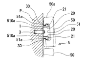
本実施の形態に示す固定レール1は、建造物の壁面である施工対象面Pの幅方向に延びるレール本体10と、このレール本体10の表面から突設する嵌合部20と、この嵌合部20の基部20aからレール幅方向に延設された支持板30(支持部)とを備えて構成されている。
Hereinafter, an embodiment in which the fixed rail of the present invention is applied to a dry tile method will be described with reference to the drawings.
The
レール本体10は、固定レール1の中央の平坦部分であり、耐食性に富むステンレス製の薄板で構成され、その長手方向の複数箇所で施工対象面Pに固定されている。また、本実施の形態では、レール長を1000mmとし、レール本体10を、図2のように胴縁2などの下地構造と交差するように上下多段に設置している。なお、図5は、アンカーボルト3を用いて、本固定レール1を施工対象面Pに設置した例である。また、図6は、ビス4を用いて設置した例である。
The rail
嵌合部20は、レール本体10の両側縁10a,10bにそれぞれ形成され、レール長手方向に延在している。また、嵌合部20の先端部分には、後に詳述するタイル裏面の溝部51に嵌合するラッチ状の突起21,21が形成されている。この突起21,21は、外側に向かって突出している。タイル裏面の溝部51をこのラッチ状の突起21,21に嵌め込むことで、タイル50がレール本体10の表面側に固定される。
The
また、嵌合部20の詳細な説明に先立って、この種の乾式工法に用いられるタイル50の構造を説明する。図4と図5は、タイル50の一例を示しており、タイル50は横に長い四角形の外観を有するとともに、その裏面側に所定の幅の溝部51が形成されている。この溝部51は、溝部51における表面側は比較的広い幅を有していて、タイルの裏面近傍には溝部51に向けて延びる一対の突部(突壁)510aが形成されており、この部分における溝部51の内寸(溝幅)はタイルの表面側の溝部の溝幅よりも狭くなっている。
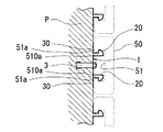
なお、上記のタイル50の構造ではなく、図6に示すような一般的な構造のものであってもよく、横に長い四角形の外観を有すると共に、その裏面側に所定の幅の溝51が形成されている。この溝51は、タイル50を長手方向に形成され、さらに、溝51の内寸(溝幅)は、溝の奥に向かうほど広くなっている。すなわち、互いに対向する内面はテーパー状に形成されている。
Prior to detailed description of the
Note that the
一方、ラッチ状の突起21,21を先端に有する嵌合部20は、レール本体10の両側縁10a,10bを往復曲成して形成されている。
具体的には、図3のように、レール本体10の両側縁10a,10bをレール本体10の表面側に曲げ起こした後、さらにその先端部分を各々外側に曲げ戻して、緩やかな弧を描くラッチ状の先端形状を得ている。
On the other hand, the
Specifically, as shown in FIG. 3, after bending both
また、本実施の形態では、このようにレール本体10の両側縁10a,10bを曲げ戻すことで、嵌合部20に強いバネ力(復元力)を与えている。
すなわち、レール本体10を形成しているステンレス製の薄板を板バネに見立て、このステンレス製の薄板を、嵌合部20に対して二重に配置することで、高い弾性率を確保している。
Moreover, in this Embodiment, strong spring force (restoring force) is given to the
That is, the stainless steel thin plate forming the
また、ラッチの向きは、レール本体10の両側縁10a,10bで異なり、ラッチ状の突起21,21を有する嵌合部20,20は、各々外側を向いている。したがって、嵌合部20にタイル50の溝部51の内面を突き当て、この状態からタイル50を嵌合部20側に強く押し込むと、図4と図5に示す構造のタイルは、溝部51の縁51aに形成された一対の突部(突壁)510aは、ラッチ状の突起21,21を乗り越えて嵌合部20,20と噛み合うため、タイル50がレール本体10に大きな負荷を掛けることも少なくなり、大型のタイルをレール本体に取り付ける場合には負荷か少なくて済むため好適である。
なお、図6に示す構造のタイルの場合にあっては、嵌合部20にタイル50の溝部51の内面を突き当て、この状態からタイル50を嵌合部20側に強く押し込むと、溝部51の縁51aは、ラッチ状の突起21,21を乗り越えて嵌合部20,20に嵌り込む。また、この状態で各突起21,21は、溝部51の内壁面51bに食い付き、タイル50を溝部51の内側から保持する。
Moreover, the direction of the latch differs at both
In the case of the tile having the structure shown in FIG. 6, when the inner surface of the
続いて、支持板30を説明する。
支持板30は、図1及び図3のように嵌合部20の基部20aからレール幅方向に延設された板状部材であり、嵌合部20同様、レール本体10の両側縁10a,10bに対称に設けられている。
Subsequently, the
The
具体的には、嵌合部20の基部20aにおいて、その自由端20b側を折り曲げて形成している。また、支持板30の表面はレール本体10と面一に設けられ、タイル装着時においてタイル50の裏面に面接触するように構成されている。また、支持板30の幅(突出量)は、タイル50の装着時において、タイル50の縁50aからはみ出ない程度とされ、支持板30はタイル50の裏側に隠れるようになっている。
Specifically, the
そして、このような構造を有する本発明の固定レール1を、施工対象面Pに釘やネジ、またアンカーボルト等を用いて固定した後、下段の固定レール1から順次タイル50を取り付けていく。
And after fixing the fixed
以下、上記した各部の構造をふまえてタイル50の取り付け方法を説明する。
タイル50の装着時には、上記のように嵌合部20の先端にタイル50の溝部51を突き当て、この状態からタイル50を施工対象面P側に強く押し込み(図4中矢印A方向)、嵌合部20に嵌め入れる。
Hereinafter, a method for attaching the
When the
また、この状態でタイル50は嵌合部20に保持されているが、嵌合部20は上述の如くバネ様の特性を有するため、嵌合部20にタイル50を嵌め込んだ状態でも位置を修正できる。また、その際、本発明の固定レールは嵌合部20の基部20aからレール幅方向に延設された支持板30を有するため、タイル50の裏面に弾性接着剤(例えば、シリコン系接着剤等)を必要に応じて塗布し、この支持板30を接着しろ(糊代)として用いることで、タイル50を定められた位置や角度で精度良く接着固定できる。
Further, in this state, the
また、隣り合うタイル50においてタイル表面の高さが揃わないときには、支持板30に弾性接着剤を厚く塗布する、或いは支持板30をタイル50側に反り起こしてタイル50に接触させるなどの調整で面精度を確保してもよい。
このように本固定レール1では、タイル50にストレスを掛けることなく取り付け精度及び固定強度を向上させることができる。
Further, when the tile surfaces of the
As described above, in the fixed
また、嵌合部20及び支持板30は、レール本体10の両側縁10a,10bに設けられているため、固定レール1の断面係数を増加させる。このためレール長手方向に延在して設けられる嵌合部20の捻り剛性や曲げ剛性が高くなり、レール長手方向の全域において一様の高い嵌合強度が得られる。また、捻れや曲げに対するレール本体10の剛性も向上するため、据え付け用ボルトの数も少なくて済む。また、言い換えれば同本数で大型のタイルや重いタイルにも対応できる。
Moreover, since the
また、本実施の形態では、嵌合部20及び支持板30をレール本体10の両側縁10a,10bに対称に設けているため、嵌合部20及び支持板30の加工・成型に伴うレール本体10の歪みや曲がりが抑えられ、この点でもタイル50の取り付け精度は向上する。
また、固定レール1の設置に関して、本固定レール1は方向性を有せず、例えば、狭い足場材の上でも長い固定レール1を振り回すことなく設置できる。
In the present embodiment, since the
Moreover, regarding the installation of the fixed
また、本実施の形態では、タイル状の部材として乾式タイル張り工法に用いられる長方形状のタイル50を例示したが、本発明は、タイルのみならず、同様の溝構造を裏面側に有する乾式レンガ工法用のレンガや、各種の乾式工法で用いられる外装材、また、内装材等の各種資材にも適用可能である。
Further, in the present embodiment, the
前記支持板30に関して、本実施の形態では接着剤を塗布する際の作業性や接着面積等を考慮して平坦な形状を選択したが、接着しろを嵌合部20の基部周囲に確保でき、また、タイル50を裏側から支持し得る形状であれば、平坦でなくてもよい。また、予めタイル側に反り起こしておいても良い。
With respect to the
また、本実施の形態では、図2のように固定レール1本に対して複数のタイル50を横一列に並べて取り付けているが、固定レール1に対して広い面積を有する大型のタイル状部材を複数本の固定レールを用いて固定してもよい。
このように本固定レール1の各部は、各種仕様に応じて変更可能である。
Further, in the present embodiment, a plurality of
Thus, each part of this fixed
1 固定レール
2 胴縁
3 アンカーボルト
4 ビス
10 レール本体
10a レール本体の側縁
10b レール本体の側縁
20 嵌合部
20a 嵌合部の基部
20b 嵌合部の自由端
21 ラッチ状の突起
30 支持板(支持部)
50 タイル
50a タイルの縁
51 溝部
51a 溝部の縁
510a 溝部の突部(突壁)
100 タイル取付装置
101 長尺板部材
102 短尺のタイル係合部材
102a 上側の突出片
102b 下側の突出片
103 シーリング材
104 ネジ
200 タイル
201 タイル裏面の溝部
P 施工対象面
W 壁面
DESCRIPTION OF
50
DESCRIPTION OF SYMBOLS 100
Claims (5)
施工対象面に取り付けられる中央部のレール本体と、
前記レール本体の表面から突設されると共に、前記タイル状部材の裏面に設けられ、開口部よりも内部が拡大するように形成された溝部に嵌合する嵌合部と、
前記嵌合部の基部から施工対象面に沿うように延設される支持部と、
を有し、
前記嵌合部は弾性を有し、前記レール本体の両側縁に設けられ、かつ、薄板からなるレール本体の側縁を往復曲成して形成される二重構造であって、前記支持部から曲げ起こし、さらに曲げ戻して前記レール本体にまで到達し、かつこの嵌合部の先端にラッチ状の突起を備え、
前記タイル状部材が前記固定レールに固定される際、前記開口部の縁部は、前記ラッチ状の突起を弾性変形させつつ、これを乗り越えることを特徴とするタイル状部材の固定レール。 It is a fixed rail for fixing the tile-shaped member to the construction target surface,
The rail body at the center that is attached to the construction target surface,
A fitting portion that protrudes from the surface of the rail body, is provided on the back surface of the tile-shaped member, and fits into a groove portion that is formed so that the inside is larger than the opening portion ;
A support portion extending from the base of the fitting portion along the construction target surface;
I have a,
The fitting part has elasticity, is provided on both side edges of the rail body, and has a double structure formed by reciprocally bending side edges of the rail body made of a thin plate, from the support part Bending up, further bending back to reach the rail body, and provided with a latch-like protrusion at the tip of this fitting portion,
When the tile-shaped member is fixed to the fixed rail, the edge of the opening, while elastically deforming the latch-like projection, the fixed rail of the tile-shaped member, characterized in Rukoto overcome this.
前記支持部は、前記嵌合部の基部からレール幅方向に延設されていることを特徴とする請求項1から3のいずれかに記載のタイル状部材の固定レール。 The fitting portion extends along a side edge of the rail body,
The fixed rail for a tile-shaped member according to any one of claims 1 to 3 , wherein the support portion extends in a rail width direction from a base portion of the fitting portion.
Priority Applications (1)
| Application Number | Priority Date | Filing Date | Title |
|---|---|---|---|
| JP2013095675A JP5714643B2 (en) | 2013-04-30 | 2013-04-30 | Tile-like fixed rail |
Applications Claiming Priority (1)
| Application Number | Priority Date | Filing Date | Title |
|---|---|---|---|
| JP2013095675A JP5714643B2 (en) | 2013-04-30 | 2013-04-30 | Tile-like fixed rail |
Publications (2)
| Publication Number | Publication Date |
|---|---|
| JP2014214588A JP2014214588A (en) | 2014-11-17 |
| JP5714643B2 true JP5714643B2 (en) | 2015-05-07 |
Family
ID=51940618
Family Applications (1)
| Application Number | Title | Priority Date | Filing Date |
|---|---|---|---|
| JP2013095675A Active JP5714643B2 (en) | 2013-04-30 | 2013-04-30 | Tile-like fixed rail |
Country Status (1)
| Country | Link |
|---|---|
| JP (1) | JP5714643B2 (en) |
Families Citing this family (1)
| Publication number | Priority date | Publication date | Assignee | Title |
|---|---|---|---|---|
| JP6548427B2 (en) * | 2015-03-31 | 2019-07-24 | ニチハ株式会社 | Fastening aid for outer wall member and method of construction thereof |
Family Cites Families (3)
| Publication number | Priority date | Publication date | Assignee | Title |
|---|---|---|---|---|
| JPS6023544U (en) * | 1983-07-27 | 1985-02-18 | 日本軽金属株式会社 | wall finishing structure |
| JPH0628593Y2 (en) * | 1991-03-22 | 1994-08-03 | 幹夫 吉松 | Wall decorative panel unit |
| JPH09105220A (en) * | 1995-10-11 | 1997-04-22 | Rio:Kk | Tile mounting structure |
-
2013
- 2013-04-30 JP JP2013095675A patent/JP5714643B2/en active Active
Also Published As
| Publication number | Publication date |
|---|---|
| JP2014214588A (en) | 2014-11-17 |
Similar Documents
| Publication | Publication Date | Title |
|---|---|---|
| US8833015B2 (en) | System for mounting wall panels to a wall structure | |
| KR200410714Y1 (en) | facing of constrution fixture | |
| KR101334320B1 (en) | Device for fixing terracotta panel on building | |
| KR101244981B1 (en) | Angle unit for wall construction | |
| US9617738B2 (en) | Auxiliary securing support and method of installing the same | |
| KR102045614B1 (en) | Slide fixing clip for earthquake-proof and construction method of exterior using the same | |
| GB2430697A (en) | Corner bead for plastering | |
| CA2683988A1 (en) | Bracket for mounting clapboards or the likes | |
| CA2597186A1 (en) | Fastening member and external wall construction structure using the same | |
| JP6490410B2 (en) | Exterior material construction structure | |
| KR100805215B1 (en) | Construction structure for panel for outer wall ornamental and method thterof | |
| KR200456095Y1 (en) | Baseboard starter and construction structure using the same | |
| CA2722715C (en) | Support bracket for anchoring overlapping cladding tiles to a wall structure | |
| JP5714643B2 (en) | Tile-like fixed rail | |
| CN211201020U (en) | Wall block material assembled decoration installation structure | |
| KR20100002876U (en) | Tile finishing frame | |
| KR101671843B1 (en) | Side contact type skin plate for building | |
| KR20110059937A (en) | Outer wall closing member installation structure forbuilding | |
| JP4229600B2 (en) | Cosmetic material mounting tool and cosmetic material mounting structure using the same | |
| JP2005139661A (en) | Decorative panel mounting structure | |
| JP2006219872A (en) | Plate construction method and plate construction structure | |
| EP2775067B1 (en) | Jamb facing profile | |
| JP2006132110A (en) | Thermal insulation panel and tile installing structure | |
| JP5919217B2 (en) | Wall structure using tiles with metal fittings and its construction method | |
| KR101472860B1 (en) | Fixing apparatus for tile |
Legal Events
| Date | Code | Title | Description |
|---|---|---|---|
| A621 | Written request for application examination |
Free format text: JAPANESE INTERMEDIATE CODE: A621 Effective date: 20141017 |
|
| A871 | Explanation of circumstances concerning accelerated examination |
Free format text: JAPANESE INTERMEDIATE CODE: A871 Effective date: 20141017 |
|
| A975 | Report on accelerated examination |
Free format text: JAPANESE INTERMEDIATE CODE: A971005 Effective date: 20141201 |
|
| A131 | Notification of reasons for refusal |
Free format text: JAPANESE INTERMEDIATE CODE: A131 Effective date: 20141209 |
|
| A521 | Written amendment |
Free format text: JAPANESE INTERMEDIATE CODE: A523 Effective date: 20150127 |
|
| TRDD | Decision of grant or rejection written | ||
| A01 | Written decision to grant a patent or to grant a registration (utility model) |
Free format text: JAPANESE INTERMEDIATE CODE: A01 Effective date: 20150224 |
|
| A61 | First payment of annual fees (during grant procedure) |
Free format text: JAPANESE INTERMEDIATE CODE: A61 Effective date: 20150311 |
|
| R150 | Certificate of patent or registration of utility model |
Ref document number: 5714643 Country of ref document: JP Free format text: JAPANESE INTERMEDIATE CODE: R150 |
|
| R250 | Receipt of annual fees |
Free format text: JAPANESE INTERMEDIATE CODE: R250 |
|
| S531 | Written request for registration of change of domicile |
Free format text: JAPANESE INTERMEDIATE CODE: R313531 |
|
| R350 | Written notification of registration of transfer |
Free format text: JAPANESE INTERMEDIATE CODE: R350 |