JP5711552B2 - Energy analyzer alignment method and apparatus - Google Patents
Energy analyzer alignment method and apparatus Download PDFInfo
- Publication number
- JP5711552B2 JP5711552B2 JP2011017142A JP2011017142A JP5711552B2 JP 5711552 B2 JP5711552 B2 JP 5711552B2 JP 2011017142 A JP2011017142 A JP 2011017142A JP 2011017142 A JP2011017142 A JP 2011017142A JP 5711552 B2 JP5711552 B2 JP 5711552B2
- Authority
- JP
- Japan
- Prior art keywords
- ispectr
- sample
- energy
- intensity
- peak position
- Prior art date
- Legal status (The legal status is an assumption and is not a legal conclusion. Google has not performed a legal analysis and makes no representation as to the accuracy of the status listed.)
- Expired - Fee Related
Links
Images

Landscapes
- Electron Sources, Ion Sources (AREA)
- Electron Tubes For Measurement (AREA)
Description
本発明は、エネルギー偏向器を備え、電子ビーム等の1次プローブビーム(電子ビーム、イオンビーム、光子ビーム、以下1次ビーム;電子ビームを例に挙げる)を試料に照射し発生する2次電子を検出することにより試料の観察を行うエネルギー分析器の軸と1次ビームの軸とを3次元的に軸合わせするための方法及び装置に関するものである。 The present invention includes an energy deflector and generates secondary electrons generated by irradiating a sample with a primary probe beam such as an electron beam (electron beam, ion beam, photon beam, hereinafter referred to as primary beam; an electron beam is taken as an example). The present invention relates to a method and apparatus for three-dimensionally aligning the axis of an energy analyzer that observes a sample by detecting the axis of the primary beam and the axis of a primary beam.
従来より、エネルギー分析器を用い、試料に電子ビーム等の1次ビームを照射し、発生する2次電子を検出することにより試料の表面状態等を分析することが行われている(特許文献1等)。エネルギー分析器(以下、分析器とも称する)を正しい状態で使うためには、試料に照射する1次ビームの軸と分析器の軸が試料上で合致していなければ最適な結果は得られない。分析者は、設計通りの性能が得られるように、両者の軸合わせを行おうとするが、通常、この軸合わせの作業は訓練と経験を積んだ者でも日常的に容易に実現できないのが実情である。十分に軸合わせをしたつもりでも試料を変えると、そのつど設定条件は最適値からはずれているということは日常普通に経験している。従来、最適の軸合わせを行うには、よく整備された分析器を十分な暖気運転の後、よく定義された試料を使って初めて可能であった。 Conventionally, an energy analyzer is used to irradiate a sample with a primary beam such as an electron beam and detect the generated secondary electrons to analyze the surface state of the sample (Patent Document 1). etc). In order to use an energy analyzer (hereinafter also referred to as an analyzer) in a correct state, an optimum result cannot be obtained unless the axis of the primary beam that irradiates the sample matches the axis of the analyzer. . Analysts try to align the two so that the designed performance can be obtained. However, it is usually the case that this alignment work cannot be easily performed on a daily basis by those who have training and experience. It is. Even if you intend to align the axes sufficiently, it is normal to experience that the setting conditions deviate from the optimum values each time the sample is changed. In the past, optimal alignment could only be achieved with a well-defined analyzer after sufficient warm-up and with a well-defined sample.
従来の最適化は、1次ビームと試料を3次元的に動かして信号強度が最大となる条件を求めることで行っていた。試料が均一ならばこの手法で特に大きな誤りは生じないが、試料が不均一で最適値の近傍に大きな信号強度を示す条件が存在すると、その点を最適としてしまう。また、最適点が見つからないときは、過去の条件に照らして統計的に妥当と思われる位置を設定しているのが現状であった。 Conventional optimization has been performed by moving the primary beam and the sample three-dimensionally to obtain conditions that maximize the signal intensity. If the sample is uniform, this method does not cause a particularly large error. However, if the sample is non-uniform and there is a condition indicating a large signal intensity in the vicinity of the optimum value, this point is optimized. In addition, when the optimum point is not found, the current position is to set a position that seems statistically appropriate in light of past conditions.
本発明は、以上のような従来技術の実情に鑑みてなされたものであり、軸合わせの作業に未習熟な者でも、容易にかつ精度良くエネルギー分析器の軸合わせを行うことができる技術を提供することを課題とする。 The present invention has been made in view of the actual situation of the prior art as described above, and is a technique that enables even an unskilled person to perform alignment work to easily and accurately align the energy analyzer. The issue is to provide.
本発明は、上記課題を解決するため、エネルギー偏向器を備え、1次ビームを試料に照射し発生する2次電子を検出することにより試料の観察を行うエネルギー分析器の軸と1次ビームの軸とを3次元的に軸合わせするための方法であって、試料を3次元的(x方向、y方向、z方向)に移動可能な試料ステージに載置し、エネルギー偏向器の直前に、スリットを備えた2次電子捕集器を設け、エネルギー偏向器の直前に設けた2次電子捕集器のスリットから特定の信号電子を通過させ、エネルギー偏向器を通して出射した特定の信号電子の前記スペクトル強度Ispectrを検出するとともに、2次電子捕集器により2次電子を捕集し、2次電子強度Isを検出し、特定の信号電子のスペクトル強度Ispectrと2次電子の強度との比Ispectr/Isを算出し、x−y平面で1次ビームを移動させ、前記の算出法によりx−y平面における位置に対する強度比Ispectr/Isの曲線を得て、ピーク位置を求めるとともに、試料をz方向に移動させ、前記の算出法によりz方向の位置に対する強度比Ispectr/Isの曲線を得て、ピーク位置を求め、x−y平面における前記ピーク位置とz方向における前記ピーク位置を最適点とすることを特徴とするエネルギー分析器の軸合わせ方法を提供する。 In order to solve the above-mentioned problems, the present invention includes an energy deflector which includes an energy deflector and observes the sample by irradiating the sample with the primary beam and detecting the secondary electrons generated. A method for aligning the axis three-dimensionally, the sample is placed on a sample stage movable in three dimensions (x direction, y direction, z direction), and immediately before the energy deflector , A secondary electron collector provided with a slit is provided, and a specific signal electron is allowed to pass through the slit of the secondary electron collector provided immediately before the energy deflector and emitted through the energy deflector. The spectrum intensity Ispectr is detected, the secondary electrons are collected by the secondary electron collector, the secondary electron intensity Is is detected, and the ratio Ispectr between the spectrum intensity Ispectr of the specific signal electron and the intensity of the secondary electron / Is is calculated Then, the primary beam is moved in the xy plane, the curve of the intensity ratio Ispectr / Is with respect to the position in the xy plane is obtained by the above calculation method, the peak position is obtained, and the sample is moved in the z direction. The curve of the intensity ratio Ispectr / Is with respect to the position in the z direction is obtained by the above calculation method, the peak position is obtained, and the peak position in the xy plane and the peak position in the z direction are taken as optimum points. A method for aligning the energy analyzer is provided.
また、本発明は、エネルギー偏向器を備え、1次ビームを試料に照射し発生する2次電子を検出することにより試料の観察を行うエネルギー分析器の軸と1次ビームの軸とを3次元的に軸合わせするための装置であって、試料を3次元的(x方向、y方向、z方向)に移動可能に載置する試料ステージと、エネルギー偏向器の直前に設けられた、スリットを備えた2次電子捕集器と、エネルギー偏向器の直前に設けた2次電子捕集器のスリットから特定の信号電子を通過させ、エネルギー偏向器を通して出射した特定の信号電子のスペクトル強度Ispectrを検出する検出器と、検出器で検出した特定の信号電子のスペクトル強度Ispectrと2次電子捕集器により捕集して得られた2次電子のスペクトル強度Isとの比Ispectr/Isを算出する割り算器と、x−y平面で1次ビームを移動させて得られ、前記割り算器で算出された、x−y平面における位置に対する強度比Ispectr/Isの曲線からピーク位置を求めるとともに、試料をz方向に移動させて得られ、前記割り算器で算出された、z方向の位置に対する強度比Ispectr/Isの曲線からピーク位置を求める、x−y平面における前記ピーク位置とz方向における前記ピーク位置を最適化位置として演算する演算手段とを備えることを特徴とするエネルギー分析器の軸合わせ装置を提供する。 The present invention also includes an energy deflector, and the axis of the energy analyzer for observing the sample by detecting secondary electrons generated by irradiating the sample with the primary beam and the axis of the primary beam are three-dimensionally arranged. Is a device for axially aligning a sample stage on which a sample is movably mounted in three dimensions (x direction, y direction, z direction), and a slit provided immediately before the energy deflector. The spectral intensity Ispectr of the specific signal electrons emitted from the secondary electron collector and the slit of the secondary electron collector provided immediately before the energy deflector is passed through the energy deflector. a detector to be detected, calculates a ratio Ispectr / is of the spectral intensity is of secondary electrons obtained was collected by a particular signal electron spectral intensity Ispectr and secondary electron collector detected by the detector division The peak position is obtained from the curve of the intensity ratio Ispectr / Is with respect to the position on the xy plane obtained by moving the primary beam on the xy plane and calculated by the divider, and the sample is moved in the z direction. The peak position is obtained from the curve of the intensity ratio Ispectr / Is with respect to the z-direction position calculated by the divider and the peak position in the xy plane and the peak position in the z-direction are optimized. An axis alignment device for an energy analyzer is provided, characterized in that the device includes an arithmetic means for calculating as a conversion position.
本発明によれば、前記技術的手法ないし技術的手段を採用したので、軸合わせの作業に訓練と経験を積んだ者でなくとも、容易にかつ精度良くエネルギー分析器の軸合わせを行うことが可能となる。 According to the present invention, since the technical method or the technical means is adopted, it is possible to easily and accurately align the energy analyzer even if it is not a person who has acquired training and experience in the alignment operation. It becomes possible.
以下、本発明の実施形態について詳細に説明する。 Hereinafter, embodiments of the present invention will be described in detail.
本発明は、エネルギー偏向器を備えたエネルギー分析器を正しい状態で使用するため、電子ビーム等の1次ビームが試料に入射し、それによって試料から放射される特定の信号電子(オージェ電子、背面散乱反射電子、背面散乱非弾性電子、エネルギー損失電子等)と2次電子(1次電子(プローブ)の励起(衝撃・入射等)により、試料より放射された全ての電子)の強度比を取ってこれが最大強度になるように最適化して3次元的に軸を合わせようとするものである。この手法によれば、たとえ1次電子ビームが時間的に揺らいでいても強度比は一定であるので安定した最適化が可能になる。この比を取るということは一種の規格化(Normalization)である。 Since the present invention uses an energy analyzer equipped with an energy deflector in the correct state, a primary beam such as an electron beam is incident on the sample, and thereby specific signal electrons (Auger electron, back surface) emitted from the sample. Scattered backscattered electrons, backscattered inelastic electrons, energy loss electrons, etc. ) and secondary electrons ( all electrons emitted from the sample due to excitation (impact, incidence, etc.) of the primary electrons (probes)) In this way, the axis is optimized in such a way that the maximum intensity is obtained and the axes are three-dimensionally aligned. According to this method, even if the primary electron beam fluctuates with time, the intensity ratio is constant, so that stable optimization is possible. Taking this ratio is a kind of normalization.
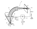
図1は、本発明による軸合わせの原理を模式的に示した説明図である。図中1は90度偏向型エネルギー分析器であり、エネルギー偏向器2を備えている。試料3はx方向、y方向、z方向の3次元方向に移動可能な試料ステージの上に載置されている。エネルギー偏向器2の直前にはスリット4が形成された2次電子捕集器5が配置されている。6は1次電子ビーム(x−y平面上に移動可能)、7は上記した特定の信号電子、8は2次電子である。エネルギー偏向器2の出口にはスリット9が設けられている。検出器10はスリット9を通過した集光された特定の信号電子7の信号強度を検出し、検出したスペクトル強度のデータIspectrを割り算器11に送る。割り算器11は2次電子捕集器5から捕集した電子の信号強度Isを受け取る。そして割り算器11は特定の信号電子7のスペクトル強度Ispectrと2次電子8のスペクトル強度Isの比Ispectr/Isを算出する。図中f0は1次電子ビーム6の試料3上の照射位置である。
FIG. 1 is an explanatory view schematically showing the principle of axis alignment according to the present invention. In the figure,
本発明では、まず、x−y平面で1次ビーム6を移動させてx−y平面における位置に対するスペクトル強度比Ispectr/Isを計測し最適点(最大値)を求める。次に試料3をz方向に上下させてz方向における位置に対するスペクトル強度比Ispectr/Isを同様に求める。図2に示す同軸円筒鏡型エネルギー分析器(CMA)のように、特定の信号電子28が大きく広がる機種では、z軸方向の最適化ではエネルギー偏向電圧もスペクトルが最大となるように調整する必要がある。なおエネルギー偏向電圧の調整はx−y平面での最適化では狭い範囲なら通常特に必要ない。このようにして3次元的にそれぞれピーク位置となる1点を最適点とする。なお計測の順番は特に問わないが、ここで述べた順序が実際的である。この最適点の算出は例えばパーソナルコンピュータ等を用いて自動的に行うことができる。
In the present invention, first, the
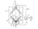
次に、実際にエネルギー分析器の軸合わせを行った例について述べる。ここでは、図2に示す同軸円筒鏡型エネルギー分析器(CMA)21を用いた。このCMA21は内筒と外筒の2重の筒で形成されるエネルギー偏向器22を備える。エネルギー偏向器22には入射スリット23と出射スリット24が設けられている。試料25は、図1の場合と同様にx方向、y方向、z方向の3次元方向に移動可能な試料ステージの上に載置されている。エネルギー偏向器22の直前には入射スリット23が形成された2次電子捕集器26が配置されている。27は1次電子ビーム、28は上記した特定の信号電子、29は2次電子である。エネルギー偏向器22の出口には検出器30が配置され、この検出器30は出射スリット24を通過した集光された特定の信号電子28のスペクトル強度を検出し、検出したスペクトル強度のデータIspectrを割り算器31に送る。割り算器31は2次電子捕集器26から捕集した電子のスペクトル強度Isを受け取る。そして割り算器31は特定の信号電子28のスペクトル強度Ispectrと2次電子29の信号強度Isとの比Ispectr/Isを算出する。
Next, an example of actually aligning the energy analyzer will be described. Here, the coaxial cylindrical mirror type energy analyzer (CMA) 21 shown in FIG. 2 was used. The CMA 21 includes an
この同軸円筒鏡型エネルギー分析器(CMA)21の動作は、基本的に図1に示す場合と同様である。すなわち、検出器30で検出した特定の信号電子28のスペクトル強度Ispectrと2次電子捕集器26により2次電子29を捕集して得られた2次電子強度Isとの比Ispectr/Isを割り算器31で求める。そしてx−y平面で1次ビーム27を移動させて得られ、割り算器31で算出された、x−y平面における位置に対するスペクトル強度比Ispectr/Isの曲線からピーク位置を求めるとともに、試料23をz方向に移動させて得られ、割り算器31で算出された、z方向の位置に対するスペクトル強度比Ispectr/Isの曲線からピーク位置を求める、図示しないパーソナルコンピュータ等の演算手段により、x−y平面における前記ピーク位置とz方向における前記ピーク位置で定まる1点を最適点として特定する。
The operation of the coaxial cylindrical mirror type energy analyzer (CMA) 21 is basically the same as that shown in FIG. That is, the ratio Ispectr / Is between the spectral intensity Ispectr of the
この同軸円筒鏡型エネルギー分析器(CMA)21を用い、表面組成にむらのある清浄化してないAl(111)について最適化を行った。1次電子ビーム27の加速電圧は2.5kV、電流は約1μAとした。
Using this coaxial cylindrical energy analyzer (CMA) 21, optimization was performed for unclean Al (111) with uneven surface composition. The acceleration voltage of the
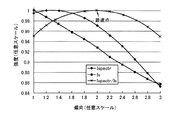
図3にエネルギー偏向器22の最適化、すなわち1次ビーム27のx−y面での最適化を行うための試料位置とスペクトル強度比との関係をグラフで示す。スペクトル強度比Ispectr/Isのピーク位置が最適点である。
FIG. 3 is a graph showing the relationship between the sample position and the spectral intensity ratio for optimization of the
また、図4に試料高さの最適化、すなわち試料25のz方向での最適化を行うための試料位置とスペクトル強度比との関係をグラフで示す。スペクトル強度比Ispectr/Isのピーク位置が最適点である。
FIG. 4 is a graph showing the relationship between the sample position and the spectral intensity ratio for optimizing the sample height, that is, for optimizing the
以上で求めたx−y面での最適点とz方向での最適点のデータに基づき、3次元的な最適点が1点だけ特定され、最適化された軸合わせを行うことができた。 Based on the data of the optimum point on the xy plane and the optimum point in the z direction obtained as described above, only one three-dimensional optimum point is specified, and the optimized axis alignment can be performed.
この実験で使用した割り算器31単独の実験では特定の信号電子28と2次電子29の狭い範囲、たとえば通常経験する10%の変動に対して割り算器31の出力(両者の比)は0.01%の変動に収まっており、大幅に性能が改善されていることがわかった。
In the experiment of the
以上、本発明の実施形態を90度偏向型エネルギー分析器と同軸円筒鏡型エネルギー分析器(CMA)により説明してきたが、180度偏向型エネルギー分析器等のその他のタイプのエネルギー分析器に対しても本発明は適用可能である。 As described above, the embodiments of the present invention have been described using the 90-degree deflection energy analyzer and the coaxial cylindrical mirror-type energy analyzer (CMA), but for other types of energy analyzers such as the 180-degree deflection energy analyzer. However, the present invention is applicable.
また、上記実施形態では1次ビームとして電子ビームを用いたが、本発明においては光、X線、やイオン等のビーム線を用いることも可能である。 In the above embodiment, an electron beam is used as the primary beam. However, in the present invention, a beam line of light, X-rays, ions, or the like can be used.
1、21 エネルギー分析器
2、22 エネルギー偏向器
3、25 試料
4、9、23、24 スリット
5、26 2次電子捕集器
6、27 1次電子ビーム
7、28 特定の信号電子
8、29 2次電子
10、30 検出器
11、31 割り算器
1,21
Claims (2)
試料を3次元的(x方向、y方向、z方向)に移動可能な試料ステージに載置し、
エネルギー偏向器の直前に、スリットを備えた2次電子捕集器を設け、
エネルギー偏向器の直前に設けた2次電子捕集器のスリットから特定の信号電子を通過させ、エネルギー偏向器を通して出射した特定の信号電子の前記スペクトル強度Ispectrを検出するとともに、2次電子捕集器により2次電子を捕集し、2次電子強度Isを検出し、特定の信号電子のスペクトル強度Ispectrと2次電子の強度との比Ispectr/Isを算出し、x−y平面で1次ビームを移動させ、前記の算出法によりx−y平面における位置に対する強度比Ispectr/Isの曲線を得て、ピーク位置を求めるとともに、試料をz方向に移動させ、前記の算出法によりz方向の位置に対する強度比Ispectr/Isの曲線を得て、ピーク位置を求め、
x−y平面における前記ピーク位置とz方向における前記ピーク位置を最適点とすることを特徴とするエネルギー分析器の軸合わせ方法。 An energy deflector is provided to three-dimensionally align the axis of the energy analyzer for observing the sample and the axis of the primary beam by detecting secondary electrons generated by irradiating the sample with the primary beam. The method of
Place the sample on a sample stage that can move in three dimensions (x direction, y direction, z direction),
Immediately before the energy deflector, provided with secondary electron collector provided with a slit,
A specific signal electron is passed through a slit of a secondary electron collector provided immediately before the energy deflector, and the spectrum intensity Ispectr of the specific signal electron emitted through the energy deflector is detected and secondary electron collection is performed. The secondary electron is collected by the detector, the secondary electron intensity Is is detected, the ratio Ispectr / Is of the spectrum intensity Ispectr of the specific signal electron and the intensity of the secondary electron is calculated, and the primary in the xy plane is calculated. The beam is moved, the curve of the intensity ratio Ispectr / Is with respect to the position in the xy plane is obtained by the above calculation method, the peak position is obtained, the sample is moved in the z direction, and the z direction is calculated by the above calculation method. Obtain the curve of the intensity ratio Ispectr / Is for the position, find the peak position,
An energy analyzer axial alignment method, wherein the peak position in the xy plane and the peak position in the z direction are optimum points.
試料を3次元的(x方向、y方向、z方向)に移動可能に載置する試料ステージと、
エネルギー偏向器の直前に設けられた、スリットを備えた2次電子捕集器と、
エネルギー偏向器の直前に設けた2次電子捕集器のスリットから特定の信号電子を通過させ、エネルギー偏向器を通して出射した特定の信号電子のスペクトル強度Ispectrを検出する検出器と、
検出器で検出した特定の信号電子のスペクトル強度Ispectrと2次電子捕集器により捕集して得られた2次電子のスペクトル強度Isとの比Ispectr/Isを算出する割り算器と、
x−y平面で1次ビームを移動させて得られ、前記割り算器で算出された、x−y平面における位置に対する強度比Ispectr/Isの曲線からピーク位置を求めるとともに、試料をz方向に移動させて得られ、前記割り算器で算出された、z方向の位置に対する強度比Ispectr/Isの曲線からピーク位置を求める、x−y平面における前記ピーク位置とz方向における前記ピーク位置を最適化位置として演算する演算手段とを備えることを特徴とするエネルギー分析器の軸合わせ装置。 An energy deflector is provided to three-dimensionally align the axis of the energy analyzer for observing the sample and the axis of the primary beam by detecting secondary electrons generated by irradiating the sample with the primary beam. Equipment,
A sample stage on which a sample is movably mounted in three dimensions (x direction, y direction, z direction);
Provided immediately before the energy deflector, and the secondary electron collector provided with a slit,
A detector that passes specific signal electrons from a slit of a secondary electron collector provided immediately before the energy deflector and detects a spectral intensity Ispectr of the specific signal electrons emitted through the energy deflector;
A divider for calculating a ratio Ispectr / Is of the spectral intensity Is of secondary electrons obtained was collected by a particular signal electron spectral intensity Ispectr and secondary electron collector detected by the detector,
The peak position is obtained from the curve of the intensity ratio Ispectr / Is with respect to the position on the xy plane obtained by moving the primary beam on the xy plane and calculated by the divider, and the sample is moved in the z direction. The peak position is obtained from the curve of the intensity ratio Ispectr / Is with respect to the z-direction position calculated by the divider, and the peak position in the xy plane and the peak position in the z-direction are optimized positions An axis alignment device for an energy analyzer, comprising: an arithmetic means for calculating as follows.
Priority Applications (1)
| Application Number | Priority Date | Filing Date | Title |
|---|---|---|---|
| JP2011017142A JP5711552B2 (en) | 2011-01-28 | 2011-01-28 | Energy analyzer alignment method and apparatus |
Applications Claiming Priority (1)
| Application Number | Priority Date | Filing Date | Title |
|---|---|---|---|
| JP2011017142A JP5711552B2 (en) | 2011-01-28 | 2011-01-28 | Energy analyzer alignment method and apparatus |
Publications (2)
| Publication Number | Publication Date |
|---|---|
| JP2012160261A JP2012160261A (en) | 2012-08-23 |
| JP5711552B2 true JP5711552B2 (en) | 2015-05-07 |
Family
ID=46840652
Family Applications (1)
| Application Number | Title | Priority Date | Filing Date |
|---|---|---|---|
| JP2011017142A Expired - Fee Related JP5711552B2 (en) | 2011-01-28 | 2011-01-28 | Energy analyzer alignment method and apparatus |
Country Status (1)
| Country | Link |
|---|---|
| JP (1) | JP5711552B2 (en) |
Family Cites Families (5)
| Publication number | Priority date | Publication date | Assignee | Title |
|---|---|---|---|---|
| JPS53138790A (en) * | 1977-05-10 | 1978-12-04 | Nippon Steel Corp | Method and device for full electronic monitor |
| JPS5831702B2 (en) * | 1979-02-28 | 1983-07-07 | 日本電子株式会社 | Augier electron spectrometer |
| JP2002181747A (en) * | 2000-12-08 | 2002-06-26 | Canon Inc | Photoelectron spectrometer and photoelectron spectrometer |
| JP2002214170A (en) * | 2001-01-22 | 2002-07-31 | Shimadzu Corp | Photoelectron spectroscopy |
| JP3741012B2 (en) * | 2001-09-17 | 2006-02-01 | 株式会社日立製作所 | Electron beam analysis method |
-
2011
- 2011-01-28 JP JP2011017142A patent/JP5711552B2/en not_active Expired - Fee Related
Also Published As
| Publication number | Publication date |
|---|---|
| JP2012160261A (en) | 2012-08-23 |
Similar Documents
| Publication | Publication Date | Title |
|---|---|---|
| Kaur et al. | Electron beam characterisation methods and devices for welding equipment | |
| KR20150143339A (en) | Fluorescent x-ray analyzer | |
| JP2016057294A5 (en) | ||
| Prasad et al. | Calibration of Thomson parabola—MCP assembly for multi-MeV ion spectroscopy | |
| CN106093094A (en) | The secondary electron spectral measurement device of a kind of dielectric material and measuring method | |
| CN103728282B (en) | The instrument analytical method of inclusion content in a kind of Fast Measurement material | |
| CN112255149B (en) | Method, system and storage medium for detecting particle size of loose particle accumulation | |
| JP5711552B2 (en) | Energy analyzer alignment method and apparatus | |
| Matsuyama et al. | Automation of multi-modal beam focusing of an MeV sub-microprobe for ion beam analysis | |
| CN110320220B (en) | Device and method for analyzing short-range ordered structure and long-range ordered structure of material | |
| Androić et al. | Measurement of the Parity-Violating Asymmetry in Inclusive Electroproduction<? format?> of π-near the Δ 0 Resonance | |
| CN109916510A (en) | Device and method for online measurement of lateral distribution of vacuum ultraviolet light based on time-of-flight spectrum | |
| Wang et al. | High resolution laser Thomson scattering system with automatic data analysis software platform for diagnosis of the low-temperature plasmas | |
| Hofmann et al. | Laser based stripping system for measurement of the transverse emittance of H-beams at the CERN LINAC4 | |
| CN109916507B (en) | Vacuum ultraviolet transverse distribution on-line measuring device and method based on ion imaging | |
| Palomino et al. | Performance of the second Deep Inelastic Neutron Scatering spectrometer at the Bariloche electron LINAC | |
| Yoshikawa et al. | Measuring electron temperature in the tandem mirror GAMMA 10 plasma using a Yttrium-Aluminum-Garnet Thomson scattering system | |
| Windelius et al. | A collinear angle-resolved photoelectron spectrometer | |
| Cheong et al. | A parallel radial mirror energy analyzer attachment for the scanning electron microscope | |
| Feng et al. | Progress of Thomson scattering diagnostic on HL-2A tokamak | |
| Liu et al. | Improvement in data processing of Thomson scattering diagnostic on HL-2A tokamak | |
| US20080061223A1 (en) | Universal X-ray fluorescence calibration technique for wire surface analysis | |
| Scandale et al. | Double-crystal setup measurements at the CERN SPS | |
| Mießner et al. | An ionization profile monitor for the determination of the FLASH and PITZ beam parameter | |
| JP2019153537A5 (en) |
Legal Events
| Date | Code | Title | Description |
|---|---|---|---|
| A621 | Written request for application examination |
Free format text: JAPANESE INTERMEDIATE CODE: A621 Effective date: 20131218 |
|
| A521 | Request for written amendment filed |
Free format text: JAPANESE INTERMEDIATE CODE: A523 Effective date: 20131218 |
|
| A977 | Report on retrieval |
Free format text: JAPANESE INTERMEDIATE CODE: A971007 Effective date: 20140725 |
|
| A131 | Notification of reasons for refusal |
Free format text: JAPANESE INTERMEDIATE CODE: A131 Effective date: 20140805 |
|
| A521 | Request for written amendment filed |
Free format text: JAPANESE INTERMEDIATE CODE: A523 Effective date: 20141006 |
|
| TRDD | Decision of grant or rejection written | ||
| A01 | Written decision to grant a patent or to grant a registration (utility model) |
Free format text: JAPANESE INTERMEDIATE CODE: A01 Effective date: 20150210 |
|
| A61 | First payment of annual fees (during grant procedure) |
Free format text: JAPANESE INTERMEDIATE CODE: A61 Effective date: 20150306 |
|
| R150 | Certificate of patent or registration of utility model |
Ref document number: 5711552 Country of ref document: JP Free format text: JAPANESE INTERMEDIATE CODE: R150 |
|
| S533 | Written request for registration of change of name |
Free format text: JAPANESE INTERMEDIATE CODE: R313533 |
|
| R350 | Written notification of registration of transfer |
Free format text: JAPANESE INTERMEDIATE CODE: R350 |
|
| S533 | Written request for registration of change of name |
Free format text: JAPANESE INTERMEDIATE CODE: R313533 |
|
| R350 | Written notification of registration of transfer |
Free format text: JAPANESE INTERMEDIATE CODE: R350 |
|
| R250 | Receipt of annual fees |
Free format text: JAPANESE INTERMEDIATE CODE: R250 |
|
| R250 | Receipt of annual fees |
Free format text: JAPANESE INTERMEDIATE CODE: R250 |
|
| R250 | Receipt of annual fees |
Free format text: JAPANESE INTERMEDIATE CODE: R250 |
|
| LAPS | Cancellation because of no payment of annual fees |