JP5711362B2 - Mold made of composite material and process using this mold - Google Patents
Mold made of composite material and process using this mold Download PDFInfo
- Publication number
- JP5711362B2 JP5711362B2 JP2013514818A JP2013514818A JP5711362B2 JP 5711362 B2 JP5711362 B2 JP 5711362B2 JP 2013514818 A JP2013514818 A JP 2013514818A JP 2013514818 A JP2013514818 A JP 2013514818A JP 5711362 B2 JP5711362 B2 JP 5711362B2
- Authority
- JP
- Japan
- Prior art keywords
- mold
- resin
- master
- bushings
- template
- Prior art date
- Legal status (The legal status is an assumption and is not a legal conclusion. Google has not performed a legal analysis and makes no representation as to the accuracy of the status listed.)
- Active
Links
- 238000000034 method Methods 0.000 title claims description 37
- 230000008569 process Effects 0.000 title claims description 35
- 239000002131 composite material Substances 0.000 title claims description 14
- 229920005989 resin Polymers 0.000 claims description 40
- 239000011347 resin Substances 0.000 claims description 40
- 239000000047 product Substances 0.000 claims description 20
- 239000000835 fiber Substances 0.000 claims description 19
- 230000000295 complement effect Effects 0.000 claims description 16
- 239000000758 substrate Substances 0.000 claims description 12
- 238000000465 moulding Methods 0.000 claims description 8
- 239000012467 final product Substances 0.000 claims description 6
- 239000000463 material Substances 0.000 claims description 6
- 238000007789 sealing Methods 0.000 claims description 3
- 230000008878 coupling Effects 0.000 claims description 2
- 238000010168 coupling process Methods 0.000 claims description 2
- 238000005859 coupling reaction Methods 0.000 claims description 2
- 238000010438 heat treatment Methods 0.000 claims 1
- 238000002347 injection Methods 0.000 description 7
- 239000007924 injection Substances 0.000 description 7
- 238000009745 resin transfer moulding Methods 0.000 description 6
- 238000004519 manufacturing process Methods 0.000 description 5
- 229920000049 Carbon (fiber) Polymers 0.000 description 4
- 239000004917 carbon fiber Substances 0.000 description 4
- 239000003822 epoxy resin Substances 0.000 description 4
- 229920000647 polyepoxide Polymers 0.000 description 4
- VNWKTOKETHGBQD-UHFFFAOYSA-N methane Chemical compound C VNWKTOKETHGBQD-UHFFFAOYSA-N 0.000 description 3
- 238000009423 ventilation Methods 0.000 description 3
- 239000000853 adhesive Substances 0.000 description 2
- 230000001070 adhesive effect Effects 0.000 description 2
- 229910052782 aluminium Inorganic materials 0.000 description 2
- XAGFODPZIPBFFR-UHFFFAOYSA-N aluminium Chemical compound [Al] XAGFODPZIPBFFR-UHFFFAOYSA-N 0.000 description 2
- 239000003795 chemical substances by application Substances 0.000 description 2
- 238000002360 preparation method Methods 0.000 description 2
- 238000003825 pressing Methods 0.000 description 2
- 238000005507 spraying Methods 0.000 description 2
- 239000002023 wood Substances 0.000 description 2
- OKTJSMMVPCPJKN-UHFFFAOYSA-N Carbon Chemical compound [C] OKTJSMMVPCPJKN-UHFFFAOYSA-N 0.000 description 1
- 229910000831 Steel Inorganic materials 0.000 description 1
- 238000007792 addition Methods 0.000 description 1
- 230000002411 adverse Effects 0.000 description 1
- 230000003796 beauty Effects 0.000 description 1
- 229910052799 carbon Inorganic materials 0.000 description 1
- 238000004140 cleaning Methods 0.000 description 1
- 230000006835 compression Effects 0.000 description 1
- 238000007906 compression Methods 0.000 description 1
- 230000007547 defect Effects 0.000 description 1
- 230000032798 delamination Effects 0.000 description 1
- 230000008021 deposition Effects 0.000 description 1
- 230000000694 effects Effects 0.000 description 1
- 239000004744 fabric Substances 0.000 description 1
- 238000005470 impregnation Methods 0.000 description 1
- 238000009434 installation Methods 0.000 description 1
- 239000007788 liquid Substances 0.000 description 1
- 229910052751 metal Inorganic materials 0.000 description 1
- 239000002184 metal Substances 0.000 description 1
- 238000012986 modification Methods 0.000 description 1
- 230000004048 modification Effects 0.000 description 1
- 238000011417 postcuring Methods 0.000 description 1
- 230000003014 reinforcing effect Effects 0.000 description 1
- 230000004044 response Effects 0.000 description 1
- 238000007493 shaping process Methods 0.000 description 1
- 239000007921 spray Substances 0.000 description 1
- 239000010959 steel Substances 0.000 description 1
- 239000000126 substance Substances 0.000 description 1
- 238000001721 transfer moulding Methods 0.000 description 1
- 238000010792 warming Methods 0.000 description 1
Images


Classifications
-
- B—PERFORMING OPERATIONS; TRANSPORTING
- B29—WORKING OF PLASTICS; WORKING OF SUBSTANCES IN A PLASTIC STATE IN GENERAL
- B29C—SHAPING OR JOINING OF PLASTICS; SHAPING OF MATERIAL IN A PLASTIC STATE, NOT OTHERWISE PROVIDED FOR; AFTER-TREATMENT OF THE SHAPED PRODUCTS, e.g. REPAIRING
- B29C33/00—Moulds or cores; Details thereof or accessories therefor
- B29C33/20—Opening, closing or clamping
-
- B—PERFORMING OPERATIONS; TRANSPORTING
- B29—WORKING OF PLASTICS; WORKING OF SUBSTANCES IN A PLASTIC STATE IN GENERAL
- B29C—SHAPING OR JOINING OF PLASTICS; SHAPING OF MATERIAL IN A PLASTIC STATE, NOT OTHERWISE PROVIDED FOR; AFTER-TREATMENT OF THE SHAPED PRODUCTS, e.g. REPAIRING
- B29C33/00—Moulds or cores; Details thereof or accessories therefor
- B29C33/30—Mounting, exchanging or centering
- B29C33/301—Modular mould systems [MMS], i.e. moulds built up by stacking mould elements, e.g. plates, blocks, rods
-
- B—PERFORMING OPERATIONS; TRANSPORTING
- B29—WORKING OF PLASTICS; WORKING OF SUBSTANCES IN A PLASTIC STATE IN GENERAL
- B29C—SHAPING OR JOINING OF PLASTICS; SHAPING OF MATERIAL IN A PLASTIC STATE, NOT OTHERWISE PROVIDED FOR; AFTER-TREATMENT OF THE SHAPED PRODUCTS, e.g. REPAIRING
- B29C33/00—Moulds or cores; Details thereof or accessories therefor
- B29C33/38—Moulds or cores; Details thereof or accessories therefor characterised by the material or the manufacturing process
- B29C33/3807—Resin-bonded materials, e.g. inorganic particles
-
- B—PERFORMING OPERATIONS; TRANSPORTING
- B29—WORKING OF PLASTICS; WORKING OF SUBSTANCES IN A PLASTIC STATE IN GENERAL
- B29C—SHAPING OR JOINING OF PLASTICS; SHAPING OF MATERIAL IN A PLASTIC STATE, NOT OTHERWISE PROVIDED FOR; AFTER-TREATMENT OF THE SHAPED PRODUCTS, e.g. REPAIRING
- B29C45/00—Injection moulding, i.e. forcing the required volume of moulding material through a nozzle into a closed mould; Apparatus therefor
- B29C45/02—Transfer moulding, i.e. transferring the required volume of moulding material by a plunger from a "shot" cavity into a mould cavity
-
- B—PERFORMING OPERATIONS; TRANSPORTING
- B29—WORKING OF PLASTICS; WORKING OF SUBSTANCES IN A PLASTIC STATE IN GENERAL
- B29C—SHAPING OR JOINING OF PLASTICS; SHAPING OF MATERIAL IN A PLASTIC STATE, NOT OTHERWISE PROVIDED FOR; AFTER-TREATMENT OF THE SHAPED PRODUCTS, e.g. REPAIRING
- B29C70/00—Shaping composites, i.e. plastics material comprising reinforcements, fillers or preformed parts, e.g. inserts
- B29C70/04—Shaping composites, i.e. plastics material comprising reinforcements, fillers or preformed parts, e.g. inserts comprising reinforcements only, e.g. self-reinforcing plastics
- B29C70/28—Shaping operations therefor
- B29C70/40—Shaping or impregnating by compression not applied
- B29C70/42—Shaping or impregnating by compression not applied for producing articles of definite length, i.e. discrete articles
- B29C70/46—Shaping or impregnating by compression not applied for producing articles of definite length, i.e. discrete articles using matched moulds, e.g. for deforming sheet moulding compounds [SMC] or prepregs
- B29C70/48—Shaping or impregnating by compression not applied for producing articles of definite length, i.e. discrete articles using matched moulds, e.g. for deforming sheet moulding compounds [SMC] or prepregs and impregnating the reinforcements in the closed mould, e.g. resin transfer moulding [RTM], e.g. by vacuum
-
- B—PERFORMING OPERATIONS; TRANSPORTING
- B29—WORKING OF PLASTICS; WORKING OF SUBSTANCES IN A PLASTIC STATE IN GENERAL
- B29C—SHAPING OR JOINING OF PLASTICS; SHAPING OF MATERIAL IN A PLASTIC STATE, NOT OTHERWISE PROVIDED FOR; AFTER-TREATMENT OF THE SHAPED PRODUCTS, e.g. REPAIRING
- B29C70/00—Shaping composites, i.e. plastics material comprising reinforcements, fillers or preformed parts, e.g. inserts
- B29C70/04—Shaping composites, i.e. plastics material comprising reinforcements, fillers or preformed parts, e.g. inserts comprising reinforcements only, e.g. self-reinforcing plastics
- B29C70/28—Shaping operations therefor
- B29C70/54—Component parts, details or accessories; Auxiliary operations, e.g. feeding or storage of prepregs or SMC after impregnation or during ageing
- B29C70/546—Measures for feeding or distributing the matrix material in the reinforcing structure
- B29C70/548—Measures for feeding or distributing the matrix material in the reinforcing structure using distribution constructions, e.g. channels incorporated in or associated with the mould
-
- B—PERFORMING OPERATIONS; TRANSPORTING
- B29—WORKING OF PLASTICS; WORKING OF SUBSTANCES IN A PLASTIC STATE IN GENERAL
- B29C—SHAPING OR JOINING OF PLASTICS; SHAPING OF MATERIAL IN A PLASTIC STATE, NOT OTHERWISE PROVIDED FOR; AFTER-TREATMENT OF THE SHAPED PRODUCTS, e.g. REPAIRING
- B29C70/00—Shaping composites, i.e. plastics material comprising reinforcements, fillers or preformed parts, e.g. inserts
- B29C70/68—Shaping composites, i.e. plastics material comprising reinforcements, fillers or preformed parts, e.g. inserts by incorporating or moulding on preformed parts, e.g. inserts or layers, e.g. foam blocks
- B29C70/72—Encapsulating inserts having non-encapsulated projections, e.g. extremities or terminal portions of electrical components
-
- B—PERFORMING OPERATIONS; TRANSPORTING
- B29—WORKING OF PLASTICS; WORKING OF SUBSTANCES IN A PLASTIC STATE IN GENERAL
- B29C—SHAPING OR JOINING OF PLASTICS; SHAPING OF MATERIAL IN A PLASTIC STATE, NOT OTHERWISE PROVIDED FOR; AFTER-TREATMENT OF THE SHAPED PRODUCTS, e.g. REPAIRING
- B29C70/00—Shaping composites, i.e. plastics material comprising reinforcements, fillers or preformed parts, e.g. inserts
- B29C70/68—Shaping composites, i.e. plastics material comprising reinforcements, fillers or preformed parts, e.g. inserts by incorporating or moulding on preformed parts, e.g. inserts or layers, e.g. foam blocks
- B29C70/86—Incorporated in coherent impregnated reinforcing layers, e.g. by winding
-
- B—PERFORMING OPERATIONS; TRANSPORTING
- B29—WORKING OF PLASTICS; WORKING OF SUBSTANCES IN A PLASTIC STATE IN GENERAL
- B29K—INDEXING SCHEME ASSOCIATED WITH SUBCLASSES B29B, B29C OR B29D, RELATING TO MOULDING MATERIALS OR TO MATERIALS FOR MOULDS, REINFORCEMENTS, FILLERS OR PREFORMED PARTS, e.g. INSERTS
- B29K2307/00—Use of elements other than metals as reinforcement
- B29K2307/04—Carbon
-
- B—PERFORMING OPERATIONS; TRANSPORTING
- B29—WORKING OF PLASTICS; WORKING OF SUBSTANCES IN A PLASTIC STATE IN GENERAL
- B29K—INDEXING SCHEME ASSOCIATED WITH SUBCLASSES B29B, B29C OR B29D, RELATING TO MOULDING MATERIALS OR TO MATERIALS FOR MOULDS, REINFORCEMENTS, FILLERS OR PREFORMED PARTS, e.g. INSERTS
- B29K2913/00—Use of textile products or fabrics as mould materials
-
- B—PERFORMING OPERATIONS; TRANSPORTING
- B29—WORKING OF PLASTICS; WORKING OF SUBSTANCES IN A PLASTIC STATE IN GENERAL
- B29L—INDEXING SCHEME ASSOCIATED WITH SUBCLASS B29C, RELATING TO PARTICULAR ARTICLES
- B29L2031/00—Other particular articles
-
- F—MECHANICAL ENGINEERING; LIGHTING; HEATING; WEAPONS; BLASTING
- F16—ENGINEERING ELEMENTS AND UNITS; GENERAL MEASURES FOR PRODUCING AND MAINTAINING EFFECTIVE FUNCTIONING OF MACHINES OR INSTALLATIONS; THERMAL INSULATION IN GENERAL
- F16L—PIPES; JOINTS OR FITTINGS FOR PIPES; SUPPORTS FOR PIPES, CABLES OR PROTECTIVE TUBING; MEANS FOR THERMAL INSULATION IN GENERAL
- F16L55/00—Devices or appurtenances for use in, or in connection with, pipes or pipe systems
- F16L55/02—Energy absorbers; Noise absorbers
-
- F—MECHANICAL ENGINEERING; LIGHTING; HEATING; WEAPONS; BLASTING
- F16—ENGINEERING ELEMENTS AND UNITS; GENERAL MEASURES FOR PRODUCING AND MAINTAINING EFFECTIVE FUNCTIONING OF MACHINES OR INSTALLATIONS; THERMAL INSULATION IN GENERAL
- F16L—PIPES; JOINTS OR FITTINGS FOR PIPES; SUPPORTS FOR PIPES, CABLES OR PROTECTIVE TUBING; MEANS FOR THERMAL INSULATION IN GENERAL
- F16L57/00—Protection of pipes or objects of similar shape against external or internal damage or wear
- F16L57/06—Protection of pipes or objects of similar shape against external or internal damage or wear against wear
Landscapes
- Engineering & Computer Science (AREA)
- Mechanical Engineering (AREA)
- Chemical & Material Sciences (AREA)
- Composite Materials (AREA)
- Manufacturing & Machinery (AREA)
- Inorganic Chemistry (AREA)
- Moulds For Moulding Plastics Or The Like (AREA)
- Casting Or Compression Moulding Of Plastics Or The Like (AREA)
- Reinforced Plastic Materials (AREA)
- Moulding By Coating Moulds (AREA)
- Glass Compositions (AREA)
Description
本発明は、複合材料で作られたモールド及びこのモールドを利用可能なプロセスに関する。
The present invention relates to a molding de及 beauty available for this molding process made of composite material.
既知のRTM(樹脂トランスファー成形)プロセスでは、樹脂の注入に必要な15bar以上もの高圧に耐える鋼で作られたモールドが用いられている。 Known RTM (resin transfer molding) processes use molds made of steel that can withstand the high pressures of 15 bar and higher required for resin injection.
繊維層の成形及びそれらに続くモールド内への堆積は自動化がされており、これによりこのプロセスで製造される部品を反復可能で経済的なものとしている一方で、RTMプロセスのモールドは重く高価で嵩張るものである。更に、金属のモールドは、成形される製品がモールド内で目詰まりを起こすことを避けるために、樹脂の硬化サイクルの間に生じる樹脂の熱膨張を考慮に入れなければならないという複雑な設計を必要とする。 The molding of the fiber layers and their subsequent deposition into the mold is automated, which makes the parts produced in this process repeatable and economical, while the RTM process mold is heavy and expensive. It is bulky. In addition, metal molds require a complex design that takes into account the thermal expansion of the resin that occurs during the resin curing cycle to avoid the molded product from becoming clogged in the mold. And
セミリジッド(半硬質な)モールドがリジッド(硬質な)モールド上に配置されるRTMライトプロセスは、これらの技術的課題を克服することが知られている。樹脂は1バール未満の圧力で注入され、樹脂の好適な流れのために空気(0.5bar)が中心最下点から吸い上げられる。2つのモールド間の接合は、2つのモールドのエッジに沿って真空(0.1bar)を作ることによって得られる。このプロセスは、軽量で経済的な装置により簡単に行うことができるが、注入圧力が比較的低くてセミリジッドモールドに対向する側の製品が荒仕上げとなってしまうため、RTMプロセスと同じ速度で同じ品質の製品を製造することはできない。更には、RTMライトプロセスを低圧力で実施すると、ドライファイバ(乾燥繊維)を完全に含浸させることができないため、低品質の部品が製造される原因となってしまう。 An RTM light process in which a semi-rigid mold is placed on a rigid mold is known to overcome these technical challenges. The resin is injected at a pressure of less than 1 bar and air (0.5 bar) is drawn up from the center lowest point for a suitable flow of resin. Bonding between the two molds is obtained by creating a vacuum (0.1 bar) along the edges of the two molds. This process can be easily performed with a light and economical device, but the same pressure at the same rate as the RTM process because the injection pressure is relatively low and the product facing the semi-rigid mold is rough. It is not possible to produce quality products. Furthermore, when the RTM light process is performed at a low pressure, dry fibers (dried fibers) cannot be completely impregnated, which causes low quality parts to be manufactured.
EP1721719号及びFR2864801号はモールドが複合材料で作られたRTMプロセスを開示している。特に、FR2864801号に記載されたモールドは同様にRTMプロセスによって作られており、ここでは複合材料でつくられたモールドとマスタ又はテンプレートとの間に繊維を配置した後にのみ樹脂が注入される。これら既知のモールドは、その製造に用いられるRTMプロセスと、予め準備された第1のモールドとその後の製造における第2のモールドとの間にテンプレートを配置する必要があることが原因で、比較的高価なものとなる。複合材料で作られた既知のモールドは、RTMプロセスの圧力に耐えるために、複雑な支持構造を更に必要とし、及び/又は、比較的厚くなければならないため、それゆえ高価なものとなってしまう。 EP 1721719 and FR 2864801 disclose RTM processes in which the mold is made of composite material. In particular, the mold described in FR 2864801 is also made by the RTM process, where the resin is injected only after placing the fibers between the mold made of composite material and the master or template. These known molds are relatively free due to the need to place a template between the RTM process used for its manufacture and the first mold prepared in advance and the second mold in subsequent manufacturing. It becomes expensive. Known molds made of composite materials require additional complex support structures to withstand the pressures of the RTM process and / or must be relatively thick and therefore expensive. .
本発明は上記不利益のすべてを除去するプロセスを提供することを目的とするものであり、即ち、迅速で経済的で自動化が容易なプロセスであって、軽量で小型な高品質の製品を得ることを可能にするプロセスを提供するものである。前記目的は、モールドとプロセスによって達成されるものであり、主たる特徴は、請求項1及び11にそれぞれ開示され、他の特徴は、残りの請求項に開示される。
The present invention aims to provide a process that eliminates all of the above disadvantages, i.e., a process that is fast, economical and easy to automate, yielding a lightweight, small and high quality product. It provides a process that makes it possible. The object is intended to be achieved by the mold and process, main features are disclosed respectively in
本発明に係るプロセスでは、予め樹脂に含浸された炭素繊維の層(プリプレグとして知られる)によって得られたモールドを提供し、温められたモールドでプレスを実施する代わりに、オーブン又はオートクレーブ内でこれらのモールドを温めることにより最終製品を硬化することを提供する。これにより、樹脂は、RTMプロセスと比べてより低い圧力で注入することができるが、それでも最終製品の基板に作り上げられるドライファイバは正確且つ完全な含浸を保証するのに十分なものである。 The process according to the present invention provides molds obtained by layers of carbon fibers pre-impregnated with resin (known as prepregs), and instead of performing the press with a warm mold, these are placed in an oven or autoclave. The final product is cured by warming the mold. This allows the resin to be injected at a lower pressure compared to the RTM process, but the dry fiber that is built into the final product substrate is still sufficient to ensure accurate and complete impregnation.
前記圧力は、特にモールドがリブ又は他の補強部材により補強されている場合には、RTMライトプロセスと比較して高いことが好ましい。 The pressure is preferably higher compared to the RTM light process, particularly when the mold is reinforced with ribs or other reinforcing members.
モールド間の接合は、樹脂の注入圧力でモールドを密閉的に閉じたままにすることが可能な特定の機械的締結手段及びガスケットを用いることにより得られる。 Bonding between the molds can be obtained by using specific mechanical fastening means and gaskets that can keep the mold hermetically closed with resin injection pressure.
モールドは、モールド間の正確で耐久性のある機械的締結を可能とし、インジェクタ、吸入口及び/又はエクストラクタなどの特定の装置を簡単かつ迅速に付加することが可能とするような特有のブッシングを包含するのが好ましい。 Mold is a unique bushing that allows accurate and durable mechanical fastening between molds and allows specific devices such as injectors, inlets and / or extractors to be added easily and quickly Are preferably included.
少なくとも1のモールドは、空洞、間隙、層間剥離又はドライゾーンなどの欠陥が存在しない製品を得るために、樹脂がキャビティ(空洞)に到達する前に樹脂を均一に流すための特有のカナル(通路)及び/又はスリットを備える。インジェクタと一致して配置された特有のウェルは、樹脂の注入圧力による樹脂の損耗を抑制する。 At least one mold has a unique canal for passage of the resin uniformly before the resin reaches the cavity to obtain a product free of defects such as cavities, gaps, delamination or dry zones ) And / or a slit. The unique well disposed in alignment with the injector suppresses resin wear due to the injection pressure of the resin.
モールドの製造は、最終製品の三次元の(立体的な)テンプレートを備える特有のマスタと、モールド内の特有の接触面(界面)を得るための参照表面、モールドを強化するために好適な対応壁面を得るための側壁、モールド内で正確にブッシングを配置するためのピンや、取り外し可能な弾性部分、及び/又はモールド内にカナル又はウェルを得るための隆起等の機械的配置とを用いることにより、迅速で正確な方法で得られることが好ましい。本発明に係るプロセスの生産性を比較的単純で経済的な方法で向上させるために、いくつかの同一のモールドが1つのマスタによって製造することができる。 Mold production is a unique master with a three-dimensional (three-dimensional) template of the final product, a reference surface to obtain a unique contact surface (interface) in the mold, a suitable response to strengthen the mold Use of mechanical arrangements such as side walls to obtain wall surfaces, pins to place bushings accurately in the mold, removable elastic parts, and / or ridges to obtain canals or wells in the mold Therefore, it is preferable to obtain it by a quick and accurate method. In order to improve the productivity of the process according to the invention in a relatively simple and economical way, several identical molds can be produced by one master.
更に、本発明に係るモールドは、軽量でそれほど嵩張らないため、使用中及び使用後、例えば、それら(モールド)が用意され、充填され、オーブン又はオートクレーブ内に配置される時などには簡単に取り扱うことができる。 Furthermore, since the mold according to the present invention is light and not so bulky, it is easily handled during and after use, for example, when they are prepared, filled, and placed in an oven or an autoclave. be able to.
モールドは、例えばこれらの熱膨張による悪影響を相殺するために、製品と実質的に同じ材料で作られるため、実質的に同じ熱膨張を受けることとなる。 Since the mold is made of substantially the same material as the product, for example to offset the adverse effects of these thermal expansions, it will experience substantially the same thermal expansion.
本プロセスにおいては、すべてのモールド、言い換えれば少なくとも2つの補完的なモールドが本発明により製造されるモールド設備を用いることにより、上記の全ての利点が著しく向上する。 In this process, all the advantages mentioned above are significantly improved by using a mold installation in which all molds, in other words at least two complementary molds, are produced according to the invention.
本発明に係るプロセス及び装置の更なる利点及び特徴は、ここに添付する図面を参照しながら、以下の詳述及び2つの非制限的な実施形態によって当業者へ明らかとされるであろう。 Further advantages and features of the process and apparatus according to the present invention will become apparent to those skilled in the art by the following detailed description and two non-limiting embodiments, with reference to the accompanying drawings.
図1に参照されるように、複合材料で作られた製品1は、既知の方法により三次元形状を有しており、例えば、高さH、幅W及び奥行きDを有する平行六面体になっている。実際には、製品1は、例えばフレーム、車体構造、カバー、アクセサリ等の必要な機能に応じて、或いは他の構造的な、流体力学な、及び/又は地上、海上又は航空の車両の美的な部品に応じて、一般的にはより複雑な形状を有しており、曲がっているか及び/又は不規則な形状であってもよい。
As shown in FIG. 1, the
図2及び図3に参照されるように、プロセスの第1の操作ステップは、例えば、CAD/CAMシステムを用いて、製品1の少なくとも1の第1の部分と実質的に同じ三次元形状で同じ大きさを有する第1のテンプレート2を製造することを含む。本実施形態では、第1のテンプレート2は、製品1と実質的に同じ幅W及び同じ奥行きDを有しているが、高さH1は、製品1の高さHよりも低い。第1のテンプレート2は、第1マスタ3の少なくとも1の第1参照表面3aに結合されるかこれと一体になっており、具体的には、実質的に平行六面体形状をなしている。第1参照表面3aは、第1のテンプレート2の周囲に突出するように、第1のテンプレート2よりも実質的に平坦で、幅が広く、奥行きが広い。1以上の第1壁4は、例えばアルミニウム、木材又はエポキシ樹脂等で作られており、第1参照表面3aと実質的に垂直で、第1参照表面3aを取り囲むように第1マスタ3の周囲に締結(固定)されている。1以上の第1リッジ5が、第1のテンプレート2の周囲において第1マスタ3の第1参照表面3a上に配置されている一方で、少なくとも1の第2リッジ6が、第1リッジ5の周囲の第1参照表面3a上に配置されている。第1リッジ5は、1以上の隆起7に接続されており、この隆起7は具体的には半球形状を有している。第1リッジ5の断面は凸状であり、具体的には実質的に半円又は半楕円形である一方で、第2リッジ6の断面は実質的に長方形であり、具体的には正方形である。複数の第1ピン8は、第2リッジ6の周囲において第1マスタ3の第1参照表面3aから同様に垂直に突出している。第1のテンプレート2、第1リッジ5、第2リッジ6及び/又は隆起7は、第1マスタ3の第1参照表面3a上に配置された単一部材のエポキシ樹脂を、デジタル制御カッターを用いて作られるか、又は、第1参照表面3a上に互いに結合されるか及び/又は配置された別々の部材を備えることができる。具体的には、第1リッジ5及び/又は第2リッジ6は、好ましくは、第1参照表面3a上に除去可能な方法で接着された弾性(エラストマ)部分により作りあげられることができる。第1のテンプレート2は、デジタル制御カッターにより成形されたエポキシ樹脂ブロックとすることができ、その後、第1参照表面3a上に接着される。
As shown in FIGS. 2 and 3, the first operational step of the process is performed in substantially the same three-dimensional shape as the at least one first portion of the
図4及び図5に参照されるように、プロセスの第2の操作ステップは、例えば、CAD/CAMシステムを用いて、製品1の少なくとも1の第2の部分と実質的に同じ三次元形状で同じ大きさを有する第2のテンプレート9を製造することを含む。本実施形態では、第2のテンプレート9は、製品1と実質的に同じ幅W及び同じ奥行きDを有しているが、高さH2は、製品1の高さHよりも低くなっており、その結果、第1のテンプレート2の高さH1と第2のテンプレート9の高さH2の合計が、製品1の高さHに対応するようになっている。第2のテンプレート9は、第2のマスタ10の少なくとも1の第2参照表面10aに結合されるかこれと一体になっており、具体的には、実質的に平行六面体形状をなしている。第2参照表面10aは、第2のテンプレート9の周囲において突出するように、第2のテンプレート9よりも実質的に平坦で、幅が広く、奥行きが広い。1以上の第2壁11は、例えばアルミニウム、木材又はエポキシ樹脂等で作られており、第2参照表面10aと実質的に垂直で、第2参照表面10aを取り囲むように第2のマスタ10の周囲に締結(固定)されている。複数の第2ピン12は、第2のテンプレート9の周囲で第2のマスタ10の第2参照表面10aから突出している。第1マスタ3上の第1ピン8の位置は、第2のマスタ10上の第2ピン12の位置と実質的に同じである。1以上の第3ピン13は、第1マスタ3の第1参照表面3a上の隆起7の位置と実質的に同じ位置で第2のマスタ10の第2参照表面10aから突出している。少なくとも1の第4ピン14及び1以上の第5ピン15は、第2のマスタ10の第2のテンプレート9から突出している。
As shown in FIGS. 4 and 5, the second operational step of the process is performed in a three-dimensional shape substantially the same as the at least one second portion of the
図6及び図7に参照されるように、プロセスの第3の操作ステップは、滑らかな通常の表面を得るために、存在する多数の孔を閉じる封止液を用いて第1マスタ3を噴霧(スプレー)することを含み、同様に、これらの表面を分離物質(剥離剤)により洗浄し、その後、第1のテンプレート2、第1参照表面3a及び第1マスタ3の第1壁4上に複数の繊維層、具体的には、樹脂に予め含浸された、プリプレグという名でも知られる炭素樹脂を設けることにより第1のモールド16を作ることを含む。図面では、簡略化のため、第1のテンプレート2及び第1参照表面3aは、下向きに向けられたものが示されているが、この操作ステップの間は、これらは層の配置を促進するために、上向きに向けられることが好ましい。具体的には、第1のモールド16は、第1の内層17及び/又は第2の内層18を備える。好ましくは、第1の内層17は、タイプ1K(1000スレッド/繊維)、PW(平織)、100g/m2基本重量、0.1mm厚の繊維を有するプリプレグを備えており、第2の内層18は、タイプ3K(3000スレッド/繊維)、TW(斜文織)2x2、200g/m2基本重量、0.25mm厚の繊維を備えている。内層17及び/又は内層18の繊維は互いに実質的に平行又は垂直である。プリプレグの帯(図示せず)は、内層17又は内層18と第1のテンプレート2の角との間か、及び/又は第1参照表面3aと第1のテンプレート2、第1壁4及び/又は第2リッジ6との間にある角の間にこれらの角をより鋭くするために配置される。
As shown in FIGS. 6 and 7, the third operational step of the process is to spray the
第1マスタ3は、第1リッジ5と第1のテンプレート2との間に、第1参照表面3aから、0.1mm〜1mmもの高さの差H3を有して突出する少なくとも1の突出部3bを備える。
The
1以上の第1の中間層19、具体的には4〜6の中間層である第1の中間層19が、内層17及び/又は内層18上に設けられ、その後、第1のブッシング20が第1ピン8に挿入され、1以上の第2の中間層21、具体的には4〜6の中間層である第2の中間層21が、第1のモールド16にそれを組み込むように第1の中間層19及び第1のブッシング20上へ設けられる。中間層19及び/又は中間層21は、タイプ12K(12000スレッド/繊維)、TW(斜文織)2x2、700g/m2基本重量、0.4mm厚の繊維を有するプリプレグを備える。中間層19及び/又は中間層21の繊維は、互いに実質的に平行であるか、斜めであるか(±45°)或いは垂直である。少なくとも1の外層22が第2の中間層21上に設けられており、これはタイプ3K(3000スレッド/繊維)、TW(斜文織)2x2、200g/m2基本重量、0.25mm厚の繊維を有するプリプレグを備える。基本重量及び/又は中間層19、21の厚みは、これにより内層17、18及び/又は外層22の基本重量及び/又は厚みよりも大きくなっている。第1のブッシング20は、内側スレッド(内側ねじ山)23を備える。
One or more first intermediate layers 19 are provided on the inner layer 17 and / or the
本出願では、具体的には、2、3又は4つの層がそれぞれ設けられた後、内層17、18、中間層19、21及び/又は外層22が、第1マスタ3上に成形ステップを用いて圧縮されるものであり、ここでは、最外層が付着防止シート及び換気材料の層によって覆われて、その後、第1マスタ3が真空バッグの中に挿入される。真空バッグは、真空バッグに対して働く外圧の影響によって第1マスタ3上に既に配置された複数の層をプレスするものである。これらの成形ステップは、真空バッグを使用し、真空バッグ上に追加圧力を生成するために、1〜10barの間の圧力のオートクレーブ中に第1マスタ3を挿入することを含む。
In the present application, specifically, after 2, 3 or 4 layers are respectively provided, the
内層17及び/又は内層18、中間層19、21及び/又は外層22は、第1リッジ5、第2リッジ6及び隆起7を覆う一方で、第1マスタ3の第1ピン8により交差された孔を有する。第1のモールド16は少なくとも全部で10つの層を備える。即ち、第1のモールド16は、少なくとも1の内層18と、8つの中間層19、21と、1の外層22を備える。本出願前にあっては、各層17、18、19、21及び/又は22は、第1マスタ3の形状及び大きさに応じて取得されたデータに基づいてデジタル制御装置を用いて形作られていた。
The inner layer 17 and / or the
第1のモールド16はその後、加圧下での硬化ステップにより完成される。ここでは、第1のブッシング20及び層17、18、19、21、22を備える第1マスタ3が、常に付着防止シート及び換気材料の層とともに真空バッグ中に挿入され、オートクレーブ内に配置され、これにより層が、樹脂を硬化させて含浸させるのに適した温度及び圧力で接合される。
The
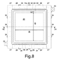
図8及び9に参照されるように、一旦オートクレーブから取り出され、冷却され、第1マスタ3から分離された第1のモールド16は、第1マスタ3の第1のテンプレート2と実質的に補完的で、実質的に同じ幅W、同じ奥行きD及び同じ高さH1を有する少なくとも1の第1の空洞24を備える。第1のモールド16は、第1の空洞24ともに単一部材で作られた少なくとも1の第1の接触面16aを備える。第1の接触面16aは、第1の空洞24の周囲で全体的に又は少なくとも部分的に突出しており、第1マスタ3の第1参照表面3aと実質的に補完的である。第1のモールド16はまた、第1マスタ3の第1壁4と実質的に一致し、第1の接触面16aと実質的に垂直な、1以上の第1側壁16bを備える。図面から分かるように、第1側壁16bは、第1の接触面16aから突出しており、これにより第1のモールド16が実質的にバット(vat)形状を有している。第1マスタ3の第1リッジ5と実質的に補完的な1以上の第1のカナル25は、第1の空洞24の周囲で第1のモールド16の第1の接触面16a上に配置される一方で、第1マスタ3の第2リッジ6と実質的に補完的な少なくとも1の第2のカナル26は、第1のカナル25の周囲で第1の接触面16a上に配置されている。第1のカナル25は、第1マスタ3の隆起7と実質的に補完的な1以上のウェル27に接続されている。複数の第1の穴28は、第1のブッシング20、つまり第1マスタ3の第1ピン8と一致して第1のモールド16の第1の接触面16a上に配置されている。
8 and 9, the
第1のモールド16が第1マスタ3から分離される際、第1のカナル25及び/又は第2のカナル26は、第1リッジ5及び/又は第2リッジ6に用いられた領域をまだ含むであろう、というのはこれらの領域は第1マスタ3から外れることができるからである。この場合、それらの領域は、再使用又置換のために、第1のカナル25及び/又は第2のカナル26から抽出される。−60°から220℃の温度に耐性を有し、最大60ショアの剛性を有する少なくとも1の管状のガスケット29が、第2のカナル26内に配置される。
When the
第1の接触面16aは、第1のカナル25と第1の空洞24との間で第1マスタ3の突出部3bと実質的に補完的な少なくとも1のスリット30を備える。スリット30の厚さH3は、0.1〜1mmを含み、スリット30の長さL1は、5〜300mmを含む。
The
好ましくは複合材料で作られ、具体的には、炭素繊維で作られた1以上のリブ31は、第1の接触面16aに対向する側の第1のモールド16上に、具体的には、第1のリブ31及び第1のモールド16を跨がって設けられた更なるプリプレグ層32及び/又は接着剤を用いて、真空バッグを用いてオートクレーブ内でプレスされ硬化されることにより、締結されている。第1のリブ31は、網を形成し、好ましくは第1のモールド16の第1側壁16bに接合される。第1のセンタリング装置33及び/又は第1の機械的締結装置34、例えばトグル留め具が、第1のモールド16の第1側壁16bの外側に固定される。
One or
図10に参照されるように、プロセスの第4の操作ステップは、第2のマスタ10の剥離剤を用いたスプレーシーリング(噴霧封止)及びクリーニングを行うことと同様に、第2のテンプレート9上、第2参照表面10a上、及び第2のマスタ10の第2壁11上に、ピン12、13及び14のための穴が設けられた複数のプリプレグ層を配置することにより第2のモールド36を製造することを含む。具体的には、第2のモールド36は、第1の内層及び/又は第2の内層、複数の中間層であって具体的には少なくとも8つの中間層と、このほかに第1のモールド16の層と同じ種類の少なくとも1の外層を備える。プリプレグの帯(ストライプ)は、角部を鋭くするために、内層と第2のテンプレート9の角部の間、及び/又は第2参照表面10aと第2のテンプレート9及び/又は第2壁11との間の角部の間に配置される。
As shown in FIG. 10, the fourth operation step of the process is similar to performing the sealing and spraying using the release agent of the
第2のブッシング37、1以上の第3のブッシング38及び少なくとも1の第4のブッシング39は、2つの中間層の間、具体的には、4つの第1の中間層のグループと8つの第2の中間層のグループの間において、第2のマスタ10の第2ピン12上、第3ピン13上及び第4ピン14上にそれぞれ挿入される。1以上の第5のブッシング40は、第5のブッシング40が第2のテンプレート9と同一平面となるように、最後の層を配置する前に第2のマスタ10の第5ピン15上に配置される。第3のブッシング38及び第4のブッシング39は実質的に同様である。第3のブッシング38、第4のブッシング39及び第5のブッシング40は、内側にねじ山がついている。2つの隣接する第1のブッシング20間又は第2のブッシング37間の距離は、35〜100mmを含み、好ましくは70mmを含む。
The
第2のモールド36の層は、第1のモールド16に関して上述した成形ステップを用いて、第2のマスタ10上に、オートクレーブを使用するか、又は使用することなく、圧縮される。
The layer of the
その後、第2のモールド36は、加圧下の硬化ステップによって完成される。ここでは、プリプレグ層及びブッシング37、38、39、40を備える第2のマスタ10が、常に付着防止シート及び換気材料の層とともに真空バッグ中に挿入され、その後オートクレーブ内に配置されて、これにより層に含浸する樹脂を硬化させるのに好適な圧力及び温度で層が接合される。
Thereafter, the
図11及び図12に参照されるように、オートクレーブから一旦取り除かれて、冷却されて、第2のマスタ10から分離された第2のモールド36は、第2のマスタ10の第2のテンプレート9と実質的に補完的で実質的に同じ幅W、同じ奥行きD及び同じ高さH2を有する少なくとも1の第2の空洞41を備える。第2のモールド36は、第2の空洞41とともに単一部材で作られた少なくとも1の第2の接触面36aを備える。第2の接触面36aは、第2の空洞41の周囲で全体的に又は少なくとも部分的に突出しており、第2のマスタ10の第2参照表面10aと実質的に補完的である。第2のモールド36はまた、第2のマスタ10の第2の側壁11と実質的に補完的で第2の接触面36aと実質的に垂直な1以上の第2の側壁36bを備える。図面から分かるように、第2の側壁36bは、第2の接触面36aから突出しており、これにより第2のモールド36が実質的にバット(vat)形状を有している。第2の穴42及び第3の穴43は、第2のブッシング37及び第3のブッシング38とそれぞれと一致して、つまり第2のマスタ10の第2ピン12及び第3ピン13とそれぞれ一致して第2のモールド36の第2の接触面36a上に配置されている。第4の穴44及び第5のブッシング40は、第2の空洞41に繋がっており、第5のブッシング40が第2の空洞41と同一平面上にある。
As shown in FIGS. 11 and 12, the
接触面16a、36aとブッシング20、37、38の間又は空洞41と第4のブッシング39との間の距離は、0.2mmよりも大きい。
The distance between the contact surfaces 16a, 36a and the
好ましくは複合材料で作られ、具体的には炭素繊維で作られた1以上の第2のリブ45は、第2の接触面36aに対向する側の第2のモールド36上に、具体的には、第2のリブ45及び第2のモールド36を跨がって塗布された更なるプリプレグの層46及び/又は接着剤を用いて締結され、オートクレーブ内において真空バッグを用いてプレスされる。第2のリブ45は、網を形成し、好ましくは、第2のモールド36の第2の側壁36bに接合される。例えばトグル留め具等の第2のセンタリング装置47及び/又は第2の機械的締結装置48が、第1のモールド16の第1のセンタリング装置33及び第1の機械的締結装置34のそれぞれに実質的に一致する位置で、第2のモールド36の第2の側壁36bの外側に固定される。
One or more
リブ31、45は、モールド16、36に、それぞれのマスタから3、10から取り外される前に配置されるのが好ましい。
The
図13及び図14に参照されるように、プロセスの第5の操作ステップは、第1のモールド16の第1の空洞24内及び/又は第2のモールド36の第2の空洞41内に1以上の基板49を予成形して配置することを含む。第2のモールド36の第3のブッシング38は、入口51に接続されたインジェクタ50を備える。2つの隣接するインジェクタ50間の距離は、400〜1500mmを含む。第2のモールド36の第4のブッシング39は、出口53に接続された吸入口52を備える。第2のモールド36の第5のブッシング40は、エクストラクタ54を備える。基板49は、繊維の層、具体的には、樹脂との結合量が重量で0から10%、好ましくは5%の乾燥した炭素繊維の層を備える。
As shown in FIGS. 13 and 14, the fifth operational step of the process is performed in the
第1のモールド16は、その後センタリング装置33、47を用いて第2のモールド36と位置合わせされ、次いで、第1のモールド16及び第2のモールド36を備えるモールド設備を作り上げるために、第2のブッシング37内に挿入され第1のブッシング20内にねじ込まれたねじ55を用いることに加えて、機械的締結装置34、48を互いに結合させることにより、第1のモールド16を第2のモールド36に締め付ける。他の実施の形態としては、ブッシング20、37のみを備えることもできるし、機械的締結装置34、38のみを備えることもできるし、及び/又は他の機械的締結装置を備えてもよい。モールド16、36は、その後一方から他方へ促され、その結果接触面16aと接触面36aとが接触して、これによりモールド16、36を密閉するように、ガスケット29をプレスする。
The
プロセスの第6の操作ステップでは、モールド16、36が、25℃から70℃の間、好ましくは60℃の温度で加熱され、この後、40℃から70℃の間の温度、具体的には60℃に加熱された樹脂が、0.5から3.5barの圧力、具体的には、1.5から2.5barの圧力で、入口51、インジェクタ50、ウェル27、第1のカナル25及びスリット30を介して第1のモールド16と第2のモールド36との間の空洞24、41に注入される。図14の矢印は、樹脂が基板49に到達して基板49を含浸するまでの樹脂の進路を示す。同時に、樹脂が吸入口52に到達しないときまでは、空気が吸入口52及び出口53から吸い込まれ、この後、樹脂の注入が中断される。樹脂が空洞24、41に注入されると、樹脂の流入区域、つまりスリット30は、排気区域、つまり吸入口52よりも低いレベルになる。前記排気の間、樹脂によって到達しない空間内の空洞24、41の圧力は、0.5bar、具体的には0.001から0.02barの間を含む圧力よりもよりも低くなる。
In the sixth operational step of the process, the
一旦樹脂注入が完了すると、モールド16、36は、オーブン又はオートクレーブ内に配置され、注入温度から90°から100℃の間を含む硬化温度にまでゆっくりと加熱され(一分間に2℃から4℃)その温度は約1時間程度保持され、その後、120℃から160℃の間を含むポストキュア温度(後硬化温度)に上昇させられ、その温度で約2時間保持される。硬化サイクルの最後には、モールド16、36が40℃から70℃の間を含む温度に冷却され、開かれ、これにより硬化樹脂内に組み込まれた基板49を備える最終製品1が、具体的には、整形して洗浄するためのエクストラクタ54を用いて抽出される。硬化及びポストキュアサイクルは、ドライファブリックを含浸するために用いられた樹脂の化学的特性に依存する。
Once resin injection is complete,
図15に参照されるように、第2のモールド36の準備の間、インジェクタ50と第3のブッシング38との間に配置された第1の環状ガスケット56を促すように、外側にねじづけされたインジェクタ50が既に第2のモールド36内に組み込まれた第3のブッシング38内にねじ込まれる(螺入される)。入口51に対して第2の環状ガスケット58を促すように、入口51はその後インジェクタ50内に挿入され、インジェクタ50にねじ込まれたリング57を用いてロックされる。吸入口52及び出口53は、インジェクタ50及び入口51と同じ構造で同じ動きをする。
As shown in FIG. 15, during preparation of the
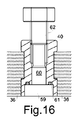
図16に参照されるように、第2のモールド36の準備の間、ステム60を備えるピストン59が、第5のブッシング40内に作られた円筒状のシート内に収容された第3の環状ガスケット61をピストン59の頭部に対して促すように、第2のモールド36内に既に配置された第5のブッシング40内へ挿入される。ピストンのステム60は、第5のブッシング40にねじ込まれたねじのついたリング62に接続され、これにより、ねじのついたリング62を回転させることによって、ピストン59の頭部が第2のモールド36から突出するために軸方向に動く。
As shown in FIG. 16, during the preparation of the
図17に参照されるように、第1のセンタリング装置33は、ねじ64を用いて軸方向に調整可能な第1の円錐又はフラストコニカルな頭部63を備える。モールド16、36の結合の間に生じうる衝撃を吸収するために、スプリング65によって、ねじ64に対する第1の頭部63の軸圧縮が可能になる。第2のセンタリング装置47は、第1の頭部63と実質的に補完的な円錐又はフラストコニカルなシートを有する第2の頭部66を備える。また、第2の頭部66は、ねじ67を用いて軸方向に調整可能である。軸方向調整とともに、モールド16、36を三次元方向に完全に結合することを確立するために、第1の頭部63及び第2の頭部66は、第1のセンタリング装置33の第1の板68及び/又は第2のセンタリング装置47の第2の板69を動かすことにより横方向に移動することができる。板68、69は、軸方向にスライドさせる方向にねじ64、67を含むための穴を備えている。
As shown in FIG. 17, the first centering
その他の実施の形態では、第1のモールド又は第2のモールドの機能的部分、つまり基板49に向けた表面を備え、プロセスの最後において最終製品1の少なくとも一部分と接するモールドの一部は、空洞を含んでいなくてもよく、平坦であるか、更には他のモールドの空洞に対して相補的な突起を備えていてもよい。この場合、マスタのテンプレートは、平坦であるか及び/又は空洞を有することができる。他の実施の形態では、第2のモールドが、第1のカナル及び/又は第2のカナルを備えることができる一方、第1のモールドがエクストラクタ、インジェクタ及び/又は吸入口を備えることができる。更なる実施の形態に係るモールド設備は、互いに連結された機械的締結装置を用いて2以上の相補的なモールドを備えていてもよい。
In other embodiments, the functional part of the first mold or the second mold, i.e. the part of the mold that is in contact with at least a part of the
図18に参照されるように、例えば本発明の第2の実施の形態においては、第1のモールド16がエクストラクタ54を備え、実質的に平坦である、つまり基板49のための空洞を欠き、第2のモールド36がガスケット29のためのカナル26を有している。
As shown in FIG. 18, for example, in the second embodiment of the present invention, the
当業者は、以下の請求の範囲に記載した範囲において、上記に記載し、図示した実施の形態に対して、更なる変形及び/又は追加が可能であろう。 Those skilled in the art will be able to make further modifications and / or additions to the embodiments described and illustrated above within the scope of the following claims.
1…(最終)製品
2…テンプレート
3…マスタ
3a…参照表面
4…壁
5…第1リッジ
6…第2リッジ
7…隆起
8…ピン
9…テンプレート
10…マスタ
10a…参照表面
11…側壁
12…ピン
13…ピン
14…ピン
15…ピン
16…モールド
16a…接触面
16b…側壁
17…内層
18…内層
19…中間層
20…ブッシング
21…中間層
22…外層
24…空洞
25…カナル
26…カナル
27…ウェル
28…穴
29…ガスケット
30…スリット
31…リブ
32…プリプレグ層
33…センタリング装置
34…機械的締結装置
36…モールド
36a…接触面
36b…側壁
37…ブッシング
38…ブッシング
39…ブッシング
3a…参照表面
3b…突出部
40…ブッシング
41…空洞
42…穴
43…穴
44…穴
45…リブ
46…層
47…センタリング装置
48…機械的締結装置
49…基板
50…インジェクタ
51…入口
52…吸入口
53…出口
54…エクストラクタ
56…環状ガスケット
57…リング
58…環状ガスケット
59…ピストン
60…ステム
61…環状ガスケット
62…リング
63…頭部
65…スプリング
66…頭部
68…板
69…板
DESCRIPTION OF
Claims (18)
複合材料で作られた少なくとも1のモールド(16、36)の少なくとも1の空洞(24、41)内に1以上の基板(49)を配置することと、
少なくとも1の補完的なモールド(16、36)に固定された前記モールド(16、36)を、機械的締結装置(20、34、37、48、55)を用いて密閉することと、
前記空洞(24、41)を排気し、樹脂を前記空洞(24、41)内に0.15MPaから0.25MPaの間の圧力で注入し、これにより前記基板(49)を、注入された前記樹脂により含浸させることと、
前記空洞(24、41)内の前記基板(49)中に含浸した前記樹脂を硬化させるために、前記モールド(16、36)を加熱すること
を含むことを特徴とするプロセス。 A process for producing a product (1) made of composite material, comprising the following operating steps: at least one cavity (24, 41) of at least one mold (16, 36) made of composite material ) Placing one or more substrates (49) in
Sealing said mold (16, 36) secured to at least one complementary mold (16, 36) using mechanical fastening devices (20, 34, 37, 48, 55);
The cavities (24, 41) are evacuated, and the resin is put into the cavities (24, 41) to the extent of 0.1. 1 5MP a or al 0. Injected at a pressure between 2 5MP a, and that thereby the substrate (49) is impregnated by injected the resin,
Heating the mold (16, 36) to cure the resin impregnated in the substrate (49) in the cavity (24, 41).
Applications Claiming Priority (3)
| Application Number | Priority Date | Filing Date | Title |
|---|---|---|---|
| ITMI2010A001072 | 2010-06-14 | ||
| ITMI2010A001072A IT1410977B1 (en) | 2010-06-14 | 2010-06-14 | PROCESS AND DEVICES FOR MANUFACTURING PRODUCTS IN COMPOSITE MATERIALS |
| PCT/IB2011/052567 WO2011158172A2 (en) | 2010-06-14 | 2011-06-14 | Mould made of a composite material, as well as master and process for its manufacturing |
Publications (2)
| Publication Number | Publication Date |
|---|---|
| JP2013533138A JP2013533138A (en) | 2013-08-22 |
| JP5711362B2 true JP5711362B2 (en) | 2015-04-30 |
Family
ID=43498632
Family Applications (1)
| Application Number | Title | Priority Date | Filing Date |
|---|---|---|---|
| JP2013514818A Active JP5711362B2 (en) | 2010-06-14 | 2011-06-14 | Mold made of composite material and process using this mold |
Country Status (10)
| Country | Link |
|---|---|
| US (2) | US9649784B2 (en) |
| EP (3) | EP2777918B1 (en) |
| JP (1) | JP5711362B2 (en) |
| CN (2) | CN103003058B (en) |
| BR (1) | BR112012031823B1 (en) |
| ES (2) | ES2785084T3 (en) |
| HK (1) | HK1210105A1 (en) |
| IT (1) | IT1410977B1 (en) |
| RU (1) | RU2555044C2 (en) |
| WO (1) | WO2011158172A2 (en) |
Families Citing this family (12)
| Publication number | Priority date | Publication date | Assignee | Title |
|---|---|---|---|---|
| IT1405233B1 (en) * | 2011-02-11 | 2014-01-03 | Automobili Lamborghini Spa | PROCESS AND SYSTEM FOR MANUFACTURING PRODUCTS IN COMPOSITE MATERIAL, AS WELL AS PRODUCTS MANUFACTURED WITH THIS PROCESS OR SYSTEM |
| FR2987306B1 (en) | 2012-02-23 | 2016-05-06 | Snecma | METHOD FOR PRODUCING RESIN TRANSFER MOLDING TOOLS |
| ITMI20120825A1 (en) * | 2012-05-14 | 2013-11-15 | Automobili Lamborghini Spa | PROCESS AND DEVICES FOR MANUFACTURING PRODUCTS IN COMPOSITE MATERIALS |
| DE102012019849B4 (en) * | 2012-10-10 | 2023-11-02 | Böllhoff Verbindungstechnik GmbH | Component with sealing plug and method for forming a component insert |
| ES2681598T3 (en) * | 2014-04-30 | 2018-09-14 | Airbus Operations S.L. | Method and device for manufacturing a part of an aircraft in composite material |
| FR3030345B1 (en) * | 2014-12-17 | 2017-09-08 | Dcns | METHOD FOR MANUFACTURING A COMPOUND MATERIAL ELEMENT HAVING AN ORIFICE AND / OR INSERT |
| IT201600130313A1 (en) | 2016-12-22 | 2018-06-22 | Automobili Lamborghini Spa | CARRYING STRUCTURE OF VEHICLE |
| WO2018125711A1 (en) * | 2016-12-27 | 2018-07-05 | Continental Structural Plastics, Inc. | Continuous channel resin transfer molding with rapid cycle time |
| CN109693401A (en) * | 2017-10-20 | 2019-04-30 | 江苏源盛复合材料技术股份有限公司 | Composite material drawing and extruding mold, molding equipment and its method, profile and its application |
| WO2020037081A1 (en) * | 2018-08-14 | 2020-02-20 | Cerniglia Anthony | Angle pin bushing and injection mold slide having same |
| CN110901103B (en) * | 2019-11-25 | 2021-07-27 | 沈阳航空航天大学 | Manufacturing method of low-cost modular composite material forming tool |
| US11801619B2 (en) * | 2021-10-05 | 2023-10-31 | The Boeing Company | Rapid tooling layup mandrel |
Family Cites Families (103)
| Publication number | Priority date | Publication date | Assignee | Title |
|---|---|---|---|---|
| US2027165A (en) * | 1934-03-16 | 1936-01-07 | Margon Corp | Molding of dolls' heads and the like |
| US2171229A (en) * | 1935-12-18 | 1939-08-29 | American Lurgi Corp | Process for manufacturing cast bearings from light metal alloys |
| US2178774A (en) * | 1937-06-18 | 1939-11-07 | Bogoslowsky Boris | Method of making a golf ball |
| US2392804A (en) * | 1941-10-13 | 1946-01-15 | Lockheed Aircraft Corp | Method of making molded drill jigs |
| US2480434A (en) * | 1946-02-16 | 1949-08-30 | Martin Askin | Locking device for metal casting molds |
| US2754546A (en) * | 1951-11-13 | 1956-07-17 | Firestone Tire & Rubber Co | Mold |
| US2834052A (en) * | 1954-01-14 | 1958-05-13 | Sherwin Williams Co | Method of making mold masters |
| US2800693A (en) * | 1954-02-18 | 1957-07-30 | Kusnery Charles | Construction for locking ejector pins |
| US3082479A (en) * | 1954-12-10 | 1963-03-26 | Barr Rubber Products Company | Porous mold |
| US2880830A (en) * | 1957-02-21 | 1959-04-07 | Frederick W Rohe | Sandwich panel and flanged insert nut assembly |
| US2961713A (en) * | 1957-05-09 | 1960-11-29 | Parker Hannifin Corp | Molding of o-rings and the like |
| US2915789A (en) * | 1957-07-25 | 1959-12-08 | Western Electric Co | Method of making drill jigs |
| US3016578A (en) * | 1957-12-11 | 1962-01-16 | Frederick W Rohe | Moldable insert panel and method of assembly |
| US3056167A (en) * | 1958-07-16 | 1962-10-02 | Proman Inc | Mold for high strength members |
| NL109348C (en) * | 1958-11-21 | |||
| GB1024582A (en) * | 1961-07-05 | 1966-03-30 | Rodgers William | A method of manufacturing a synthetic resin moulding reinforced with fibrous material |
| US3212181A (en) * | 1962-05-14 | 1965-10-19 | Ace Drill Bushing Co Inc | Method of locating drill jig parts in making a drill jig |
| US3305996A (en) * | 1964-05-04 | 1967-02-28 | North American Aviation Inc | Panel fastener |
| US3421184A (en) * | 1966-09-21 | 1969-01-14 | Youngstown Sheet And Tube Co | Clamps for molds |
| US3433450A (en) * | 1966-12-12 | 1969-03-18 | Robert F Brunner | Ejector and mold plate attachment for plastic molding machines |
| US3566447A (en) * | 1967-02-06 | 1971-03-02 | British Industrial Plastics | Moulding equipment |
| US3620119A (en) * | 1968-08-21 | 1971-11-16 | King John O Jun | Fasteners and method and apparatus for forming fasteners |
| FR2052215A5 (en) * | 1969-07-25 | 1971-04-09 | Crouzet & Cie | |
| US3636241A (en) * | 1970-11-23 | 1972-01-18 | Bell Telephone Labor Inc | Telephone cable splice case |
| US4120632A (en) * | 1972-01-12 | 1978-10-17 | Klepper-Werke Kommanditgesellschaft | Molds for production of plastics material boats |
| US3835906A (en) * | 1972-07-17 | 1974-09-17 | R Dietlein | Plastic sleeve encapsulated fastener locking insert and assembly |
| US3904243A (en) * | 1974-09-23 | 1975-09-09 | Krueger Metal Products | Fiberglass shell construction with screw anchor inserts |
| US3945070A (en) * | 1975-05-19 | 1976-03-23 | Avia Instrument Company | Wire thread cast insert |
| SE7810976L (en) * | 1978-10-20 | 1980-04-21 | Kubat Josef | FORM EXPRESSION OF HIGH-MOLECULE POLYETE WITH USE OF INCREASED FORM TEMPERATURE |
| DE2905356A1 (en) * | 1979-02-13 | 1980-08-21 | Bayer Ag | HOMOGENEOUS, THERMOPLASTIC MIXTURES OF PROPYLENE-ETHYLENE / COPOLYMERISATEN AND LIQUID, SATURATED DIORGANOPOLYSILOXANS OF A SPECIFIC VISCOSITY RANGE |
| US4267142A (en) * | 1979-10-22 | 1981-05-12 | Lankheet Jay A | Reinforced resin molding method and apparatus |
| US4359443A (en) * | 1980-09-02 | 1982-11-16 | Fiber Glass Tooling & Specialties | Venting arrangement for matched molds and method |
| US4372741A (en) * | 1980-10-31 | 1983-02-08 | Discovision Associates | Hot sprue valve assembly for an injection molding machine |
| FR2497524B1 (en) * | 1981-01-07 | 1985-12-13 | Rhone Poulenc Spec Chim | |
| US4386868A (en) * | 1981-01-12 | 1983-06-07 | Bluver David B | Leader pin locking device |
| US4391579A (en) * | 1981-09-23 | 1983-07-05 | Discovision Associates | Hot sprue valve assembly for an injection molding machine |
| DE3304882A1 (en) * | 1983-02-12 | 1984-08-16 | Röhm GmbH, 6100 Darmstadt | METHOD FOR PRODUCING A FOAM COMPOSITE BODY |
| HU189254B (en) * | 1983-03-25 | 1986-06-30 | Boros,Gyoergy,Hu | Prefabricated plate members of tool body particularly for tools of closed hollow |
| US4696711A (en) * | 1983-09-30 | 1987-09-29 | Mcdonnell Douglas Corporation | Method for forming holes in composites |
| ES8705288A1 (en) * | 1985-07-03 | 1987-05-01 | Ver Edelstahlwerke Ag | Apparatus for the pressure-supported moulding, in particular injection moulding, of mould bodies. |
| US4812193A (en) * | 1986-12-22 | 1989-03-14 | Gauron Richard F | Inset panel fastener and method of using |
| US4859528A (en) * | 1987-04-17 | 1989-08-22 | Hexcel Corporation | Composite tooling |
| US4920161A (en) * | 1988-06-24 | 1990-04-24 | General Motors Corporation | High strength epoxy tooling compositions |
| US4944824A (en) * | 1988-09-23 | 1990-07-31 | E. I. Du Pont De Nemours And Company | Process for preparation of tooling of carbon fiber reinforced polyimide for composites manufacture |
| GB8902841D0 (en) * | 1989-02-09 | 1989-03-30 | Williams Design Engineering | Method and apparatus for moulding a fluid settable material |
| GB2232630A (en) * | 1989-06-17 | 1990-12-19 | Osteon Limited | Improvements in or relating to the production of anatomical replicas |
| ES2091810T3 (en) * | 1989-08-07 | 1996-11-16 | Nissan Motor | EPOXY RESIN MOLD FILLED WITH METALLIC POWDER AND METHOD FOR ITS MANUFACTURE. |
| JPH03140213A (en) * | 1989-10-26 | 1991-06-14 | Matsushita Electric Works Ltd | Resin mold for molding resin |
| US5206076A (en) * | 1990-01-19 | 1993-04-27 | American Standard Inc. | Elastomeric mold seals |
| US5039468A (en) * | 1990-01-24 | 1991-08-13 | Sellers Stephen N | Method of making a stained glass article |
| GB9008951D0 (en) | 1990-04-20 | 1990-06-20 | British Aerospace | Composite material manufacture |
| FR2664529B1 (en) * | 1990-07-12 | 1994-04-01 | Snecma | PROCESS FOR THE MANUFACTURE OF REVOLUTION PARTS HAVING SINGULARITIES OF SHAPE, IN FILAMENTARY WINDING. |
| US5252165A (en) * | 1990-09-20 | 1993-10-12 | United Technologies Corporation | Method of making contoured fiber reinforced body |
| FR2675732B3 (en) * | 1991-04-23 | 1993-09-17 | Stratime Cappello Systemes | USE OF THE R.T.M TECHNIQUE FOR THE MANUFACTURE OF A SELF-SUPPORTING STRUCTURE FOR VEHICLE. |
| US5277854A (en) * | 1991-06-06 | 1994-01-11 | Hunt John F | Methods and apparatus for making grids from fibers |
| CA2076578A1 (en) * | 1992-08-21 | 1994-02-22 | Miroslav Milinkovic | Mandrel for use in nickel vapour deposition processes and nickel molds made therefrom |
| CN1050576C (en) | 1993-09-14 | 2000-03-22 | 株式会社利肯 | An electric powered bicycle |
| JPH07195376A (en) | 1993-12-28 | 1995-08-01 | Honda Motor Co Ltd | Mold for fiber reinforced plastic, master mold and production of them |
| US5730926A (en) * | 1994-07-15 | 1998-03-24 | Asahi Kasei Kogyo Kabushiki Kaisha | Method for the non-resin fluid-assisted injection molding of a resin |
| US5939007A (en) * | 1994-08-31 | 1999-08-17 | Sikorsky Aircraft Corporation | Method for manufacture of a fiber reinforced composite spar for rotary wing aircraft |
| JPH08323870A (en) * | 1995-05-31 | 1996-12-10 | Toyota Autom Loom Works Ltd | Molding die for fiber-reinforced composite material |
| US5958325A (en) * | 1995-06-07 | 1999-09-28 | Tpi Technology, Inc. | Large composite structures and a method for production of large composite structures incorporating a resin distribution network |
| US5744173A (en) * | 1996-02-27 | 1998-04-28 | Aeroquip Corporation | Mold inserts for injection moldings |
| US20040017020A1 (en) * | 2002-07-26 | 2004-01-29 | David Loving | Process for fiberglass molding using a vacuum |
| AU7176998A (en) * | 1997-05-06 | 1998-11-27 | Boeing Company, The | Hybrid lay-up tool |
| US6069319A (en) * | 1997-07-22 | 2000-05-30 | Lear Automotive Dearborn, Inc. | Foamed-in harnesses |
| FR2771960B1 (en) * | 1997-12-09 | 2000-02-04 | Eurocopter France | DEVICE FOR MANUFACTURING A COMPOSITE ELEMENT BY VACUUM INJECTION MOLDING OF A RESIN, AND METHOD FOR IMPLEMENTING SAID DEVICE |
| FR2777496B1 (en) * | 1998-04-17 | 2000-08-04 | Sunkiss Aeronautique | PROCESS FOR OBTAINING, REPAIRING OR RECONSTRUCTING AN OBJECT WITH A PART OR COMPOSITE MATERIAL |
| US6091063A (en) * | 1998-11-06 | 2000-07-18 | The Boeing Company | Method for improving thermal uniformity in induction heating processes |
| US7081219B2 (en) * | 1999-03-18 | 2006-07-25 | Stewart David H | Method and machine for manufacturing molded structures using zoned pressure molding |
| US6319447B1 (en) * | 1999-04-09 | 2001-11-20 | The Boeing Company | Resin transfer molding process |
| US6309587B1 (en) * | 1999-08-13 | 2001-10-30 | Jeffrey L. Gniatczyk | Composite molding tools and parts and processes of forming molding tools |
| US6186707B1 (en) * | 1999-09-10 | 2001-02-13 | The Boeing Company | Apparatus for locating holes to be drilled in post cure composite structures and associated method |
| US6346209B1 (en) * | 2000-04-07 | 2002-02-12 | The Goodyear Tire & Rubber Company | Method and apparatus for ejecting molded articles |
| WO2001098056A1 (en) * | 2000-06-19 | 2001-12-27 | Progressive Components International Corporation | A core pin and sleeve and method of using same |
| US6638466B1 (en) * | 2000-12-28 | 2003-10-28 | Raytheon Aircraft Company | Methods of manufacturing separable structures |
| JP2003014938A (en) | 2001-04-12 | 2003-01-15 | Mitsubishi Engineering Plastics Corp | Light transmission plate composed of transparent resin, method for molding the same, bushing, metallic mold assembling body and surface light source device |
| US6787071B2 (en) * | 2001-06-11 | 2004-09-07 | General Electric Company | Method and apparatus for producing data storage media |
| JP4089383B2 (en) * | 2001-10-30 | 2008-05-28 | ソニー株式会社 | Information recording medium manufacturing method and manufacturing apparatus |
| GB0127154D0 (en) * | 2001-11-13 | 2002-01-02 | Bae Systems Plc | A mould tool |
| US20040096535A1 (en) * | 2002-11-15 | 2004-05-20 | Hudecek Robert W. | Compression molding apparatus having replaceable mold inserts |
| FR2864801B1 (en) * | 2004-01-07 | 2007-06-29 | Lucio Cappello | TOOLING FOR MOLDING IN R.T.M. OF COMPOSITE MATERIALS CONSISTING OF SELF-SUPPORTING MUSSELS MADE IN R.T.M. AND AUTONOMOUS METAL STRUCTURES |
| KR101151966B1 (en) * | 2004-02-17 | 2012-06-01 | 도레이 카부시키가이샤 | Rtm molding method and device |
| US8640428B2 (en) * | 2004-04-30 | 2014-02-04 | Indian Institute Of Technology, Bombay | Strength enhancing insert assemblies |
| FR2879498B1 (en) * | 2004-12-16 | 2009-01-30 | Snecma Propulsion Solide Sa | DENSIFICATION OF FIBROUS STRUCTURES BY RTM FOR THE PRODUCTION OF PARTS IN COMPOSITE MATERIAL |
| US7510390B2 (en) * | 2005-07-13 | 2009-03-31 | Hexcel Corporation | Machinable composite mold |
| US8709325B2 (en) * | 2005-07-21 | 2014-04-29 | Michael J. Stevenson | Liquid low temperature injection molding process |
| TW200716361A (en) * | 2005-07-27 | 2007-05-01 | Mitsubishi Heavy Ind Ltd | Rtm process |
| US7972129B2 (en) * | 2005-09-16 | 2011-07-05 | O'donoghue Joseph | Compound tooling system for molding applications |
| DE102005050143B3 (en) * | 2005-10-19 | 2007-01-04 | Airbus Deutschland Gmbh | Aircraft loading container has sandwich construction with inner hollow shell and radial legs to outer shell defining cells |
| DE102005053690A1 (en) * | 2005-11-10 | 2007-05-31 | Airbus Deutschland Gmbh | Tool, assembly and method for manufacturing a component, component |
| JP4817818B2 (en) * | 2005-11-29 | 2011-11-16 | Towa株式会社 | Resin sealing device and chase unit removal method |
| EP1960178A1 (en) * | 2005-12-12 | 2008-08-27 | Green Tokai Co., Ltd. | Molding apparatus |
| CA2636685A1 (en) * | 2006-01-17 | 2007-08-02 | Lrm Industries, Llc | Molded panel, molded panel system and connection system |
| KR101332539B1 (en) * | 2006-03-08 | 2013-11-22 | 도레이 카부시키가이샤 | Process for producing fiber-reinforced resin |
| US7628942B1 (en) * | 2006-04-25 | 2009-12-08 | The United States Of America As Represented By The United States Department Of Energy | Resin infiltration transfer technique |
| US7862322B2 (en) * | 2006-04-25 | 2011-01-04 | Florida State University Research Foundation | Resin infusion between double flexible tooling system |
| US8092210B2 (en) * | 2006-05-19 | 2012-01-10 | Lopez Sanchez Manuel | Mold for producing door cores |
| US7943075B2 (en) * | 2006-06-09 | 2011-05-17 | Honda Motor Co., Ltd. | Method for producing fiber-reinforced composite |
| CN101743117B (en) * | 2007-02-28 | 2015-02-18 | 空中客车西班牙运营有限责任公司 | Tool and method for producing aircraft ring frames from a composite material |
| US20090230281A1 (en) * | 2008-03-17 | 2009-09-17 | Cheng Uei Precision Industry Co., Ltd. | Mold with unloading mechanism |
| CN102770256B (en) * | 2009-12-18 | 2016-08-24 | 3M创新有限公司 | Molding TLCP and the goods being made from |
| IT1401106B1 (en) * | 2010-07-02 | 2013-07-12 | Automobili Lamborghini Spa | PROCESS, MOLDS, DEVICES AND KITS FOR MANUFACTURING PRODUCTS IN COMPOSITE MATERIALS, AS WELL AS PRODUCTS MANUFACTURED WITH THIS PROCESS AND / OR WITH THESE MEANS |
-
2010
- 2010-06-14 IT ITMI2010A001072A patent/IT1410977B1/en active
-
2011
- 2011-06-14 ES ES14171906T patent/ES2785084T3/en active Active
- 2011-06-14 EP EP14171906.2A patent/EP2777918B1/en active Active
- 2011-06-14 EP EP12199103.8A patent/EP2574449B1/en active Active
- 2011-06-14 JP JP2013514818A patent/JP5711362B2/en active Active
- 2011-06-14 WO PCT/IB2011/052567 patent/WO2011158172A2/en active Application Filing
- 2011-06-14 CN CN201180028871.9A patent/CN103003058B/en active Active
- 2011-06-14 BR BR112012031823-3A patent/BR112012031823B1/en not_active IP Right Cessation
- 2011-06-14 ES ES12199103T patent/ES2785298T3/en active Active
- 2011-06-14 RU RU2013101582/05A patent/RU2555044C2/en active
- 2011-06-14 EP EP11738812A patent/EP2571672A2/en not_active Withdrawn
- 2011-06-14 CN CN201410740968.8A patent/CN104608400B/en active Active
-
2012
- 2012-12-04 US US13/693,387 patent/US9649784B2/en active Active
-
2015
- 2015-04-21 US US14/692,418 patent/US10960579B2/en active Active
- 2015-11-11 HK HK15111122.1A patent/HK1210105A1/en unknown
Also Published As
| Publication number | Publication date |
|---|---|
| US20130093126A1 (en) | 2013-04-18 |
| EP2777918A1 (en) | 2014-09-17 |
| US20150224678A1 (en) | 2015-08-13 |
| HK1210105A1 (en) | 2016-04-15 |
| US10960579B2 (en) | 2021-03-30 |
| IT1410977B1 (en) | 2014-10-03 |
| RU2555044C2 (en) | 2015-07-10 |
| EP2574449A2 (en) | 2013-04-03 |
| JP2013533138A (en) | 2013-08-22 |
| ITMI20101072A1 (en) | 2011-12-15 |
| EP2574449B1 (en) | 2020-02-19 |
| ES2785084T3 (en) | 2020-10-05 |
| WO2011158172A3 (en) | 2012-03-29 |
| WO2011158172A2 (en) | 2011-12-22 |
| US9649784B2 (en) | 2017-05-16 |
| BR112012031823B1 (en) | 2020-10-27 |
| CN104608400B (en) | 2017-12-12 |
| CN103003058A (en) | 2013-03-27 |
| BR112012031823A2 (en) | 2016-11-08 |
| EP2571672A2 (en) | 2013-03-27 |
| RU2013101582A (en) | 2014-07-20 |
| ES2785298T3 (en) | 2020-10-06 |
| CN103003058B (en) | 2015-10-07 |
| CN104608400A (en) | 2015-05-13 |
| EP2574449A3 (en) | 2013-12-11 |
| EP2777918B1 (en) | 2020-02-12 |
Similar Documents
| Publication | Publication Date | Title |
|---|---|---|
| JP5711362B2 (en) | Mold made of composite material and process using this mold | |
| CN103909658B (en) | Composite material connecting skirt forming method and mold and inner rubber core mold forming mold | |
| RU2438866C2 (en) | Method of producing structural component from composite material reinforced by fibres for aerospace engineering, moulding core for production of said component, and component thus produced and/or by means of said core | |
| JP6016814B2 (en) | Manufacturing method of composite material product, manufacturing apparatus thereof, and product manufactured by this method or apparatus | |
| CN104589670B (en) | A kind of gas path design method of composite cavity structure air bag shaping | |
| CN102765198A (en) | Vacuum assisted molding system of composite and molding method of composite | |
| WO2009115736A3 (en) | Method and device for moulding a curved part made from composite material and corresponding part | |
| US9067345B2 (en) | Mold for manufacture of fiber composite parts and method of manufacture of fiber composite parts with such a mold | |
| JP2017121800A (en) | Textured caul plate and method of use | |
| US9522486B2 (en) | Method of producing tooling for resin transfer molding | |
| JP5519149B2 (en) | Apparatus for injecting resin into at least one fiber layer of a fiber reinforced product to be manufactured | |
| KR101447136B1 (en) | Method for Forming Fiber Reinforced Plastic Composite | |
| US20150014898A1 (en) | Device and method for producing a moulded part from a composite material | |
| US10486377B2 (en) | Method of moulding a composite article and mould | |
| US20130180642A1 (en) | Self-stiffened composite panel and process for making same | |
| US11707897B2 (en) | Method for producing composite material, fiber base material, and shaping mold for fiber base material | |
| JP6915379B2 (en) | Composite material molding method and molding equipment | |
| ITMI20120825A1 (en) | PROCESS AND DEVICES FOR MANUFACTURING PRODUCTS IN COMPOSITE MATERIALS | |
| JP5840889B2 (en) | RTM molding method |
Legal Events
| Date | Code | Title | Description |
|---|---|---|---|
| A621 | Written request for application examination |
Free format text: JAPANESE INTERMEDIATE CODE: A621 Effective date: 20140106 |
|
| A131 | Notification of reasons for refusal |
Free format text: JAPANESE INTERMEDIATE CODE: A131 Effective date: 20141007 |
|
| A977 | Report on retrieval |
Free format text: JAPANESE INTERMEDIATE CODE: A971007 Effective date: 20141008 |
|
| A521 | Request for written amendment filed |
Free format text: JAPANESE INTERMEDIATE CODE: A523 Effective date: 20150107 |
|
| TRDD | Decision of grant or rejection written | ||
| A01 | Written decision to grant a patent or to grant a registration (utility model) |
Free format text: JAPANESE INTERMEDIATE CODE: A01 Effective date: 20150203 |
|
| A61 | First payment of annual fees (during grant procedure) |
Free format text: JAPANESE INTERMEDIATE CODE: A61 Effective date: 20150305 |
|
| R150 | Certificate of patent or registration of utility model |
Ref document number: 5711362 Country of ref document: JP Free format text: JAPANESE INTERMEDIATE CODE: R150 |
|
| R250 | Receipt of annual fees |
Free format text: JAPANESE INTERMEDIATE CODE: R250 |
|
| R250 | Receipt of annual fees |
Free format text: JAPANESE INTERMEDIATE CODE: R250 |
|
| R250 | Receipt of annual fees |
Free format text: JAPANESE INTERMEDIATE CODE: R250 |
|
| R250 | Receipt of annual fees |
Free format text: JAPANESE INTERMEDIATE CODE: R250 |
|
| R250 | Receipt of annual fees |
Free format text: JAPANESE INTERMEDIATE CODE: R250 |
|
| R250 | Receipt of annual fees |
Free format text: JAPANESE INTERMEDIATE CODE: R250 |
|
| R250 | Receipt of annual fees |
Free format text: JAPANESE INTERMEDIATE CODE: R250 |